generation of quadrilateral mesh over analytical curved
TRANSCRIPT

~ ' : . - . . :4" , ~]'~
ELSEVIER Finite Elements in Analysis and Design 27 (1997) 251-272
FINITE ELEMENTS IN ANALYSIS AND DESIGN
Generation of quadrilateral mesh over analytical curved surfaces
T.S. Lau, S.H. Lo*, C.K. Lee
Department of Civil and Structural Engineerin 9, The University of Hon 9 Kong, Pokfulam Road, Hong Kono, Hon9 Kon9
Abstract
An automatic adaptive quadrilateral mesh conversion scheme for the generation of adaptive refinement meshes over analytical curved surfaces is proposed. The starting point of the quadrilateral mesh generator is a background triangular mesh of the curved surface. By a carefully controlled process to merge two triangles at a time the triangular mesh can be completely converted to quadrilaterals. A rapidly graded quadrilateral mesh with node spacing compatible with the desired element size distribution can be obtained from a well-graded triangular mesh. The quality of the quadrilateral mesh can be subsequently enhanced by a series of mesh modifications and element shape improvement procedures. The present scheme can be used in conjunction with an adaptive surface triangular mesh generator to generate quadrilateral meshes suitable for adaptive shell refinement analysis. © 1997 Elsevier Science B.V.
Keywords: Automatic eLdaptive quadrilateral mesh generation; Analytical curved surfaces; Adaptive refinement analysis
I. Introduction
There are at least two reasons that make the quadrilateral mesh more preferable to the triangu- lar mesh for the finite element analysis of shell structures. First, as pointed out by a number of researches [1-3] that a high-quality quadrilateral mesh can give better solution than a triangular mesh with similar :number of degrees of freedom. Second, most of the simple, robust and efficient degenerated shell elements are quadrilateral such as those based on the assumed strain approach [4, 5]. Although some robust and efficient triangular shell elements exist, most of them are either lim- ited to linear facet elements [6] or formulated in a more complex form such as the inclusion of discrete Kirchhoff constraint with nodeless variable or bubble functions [7] which make them less favorable compared[ to the standard quadratic or cubic assumed strain quadrilateral elements in prac- tical appl ica t ions . There fore , an au toma t i c quadr i la tera l m e s h genera to r is a v e r y va luab le tool for the i m p l e m e n t a t i o n o f genera l and adap t ive shell finite e l emen t analys is p rog ram.
* Corresponding author.
0168-874X/97/$17.00 @ 1997 Elsevier Science B.V. All rights reserved PII S 0 1 6 8 - 8 7 4 X ( 9 ; 1 ) 0 0 0 1 5-2

252 T.S. Lau et al./Finite Elements in Analysis and Design 27 (1997) 251-272
Although the generation of quadrilateral mesh can be dated back to the early 70s when Zienkiewicz and Phillips [8] presented the isoparametric mapping techniques, no successful development of a fully automatic graded quadrilateral mesh generator for arbitrary domain has been found until this decade. Two different approaches, namely the direct and the indirect approaches are used for the generation of quadrilateral elements.
(1) Direct schemes: The most classical method of this type is the mapping procedure [8-11]. Elements are generated in the physical domain by mapping a regular or nearly regular quadrilateral mesh on the parent parametric coordinate plane to the physical domain which can either be a plane or a curved surface. The element generated are usually of high quality unless the physical domain is a seriously distorted image of the parametric plane. However, this technique is mainly suitable for simple, simply connected domains. Extra manually domain subdivision procedure is required for irregular, multi-connected regions [12]. Moreover, the degree of gradation that can be achieved by this method is very limited. As the ability of a mesh generator to achieve a given element density distribution is a key factor governing its usefulness in an adaptive finite element analysis, quadrilateral mesh generator of this type is generally not suitable for adaptive analysis. Besides the mapping technique, Talbert and Parkinson [13] proposed a recursive decomposition method for meshing of general multi-connected domain. In the same year, Blacker [14] proposed the paving technique for the generation of graded quadrilateral meshes without the need of domain subdivision in case of complex multi-connected domain.
(2) Indirect schemes: In the indirect scheme, quadrilateral elements are formed by converting the elements in a background triangular mesh into quadrilaterals through the operations of merging and splitting. A simple conversion scheme was proposed by Lo [15] using selective removal of diagonals between triangles for the generation of meshes with mixed types of elements. Later, the scheme was extended by Lee and Lo [16] for generating complete quadrilateral meshes over arbitrary planar regions. A similar method was also proposed by Johnston et al. [17] for converting all the triangles in a triangular mesh into quadrilaterals. A different method which performs the merging process simultaneously with the generation of triangular element was developed by Zhu et al. [18] based on the triangular mesh generator implemented by Peraire [19]. Since in the indirect schemes, quadrilateral elements are generated from the background triangular mesh, it is not difficult to achieve a high element density gradient through a highly graded background mesh. Irregular domains with multi-openings can also be handled as easy as regular, simply connected domains with a suitable triangular mesh generation scheme such as the surface mesh generator developed by Lau and Lo [20]. Unfortunately, the quality of the elements from such schemes are usually of lower quality compared to those by the direct schemes. Therefore, mesh quality enhancement procedures are usually required for the production of high quality graded quadrilateral mesh suitable for adaptive analysis.
2. The quadrilateral mesh generation algorithm
2.1. Basic requirements
The algorithm presented in this paper is an indirect scheme based on the systematic merging technique proposed by Lee and Lo [ 16] for the generation of quadrilateral meshes in planar domain. It is extended for quadrilateral mesh generation over general analytical curved surfaces. Unlike the

T. S. Lau e t al. / Finite Elements in Analysis and Desion 27 (1997) 251-272 253
Fig. 1. Formation of poor-shaped quadrilaterals.
method presented by Zhu [18], the boundary segments are preserved after the conversion which are necessary for joining meshes from different surface patches. The whole process can be divided into three stages, namely, the pre-processing of background triangular mesh, the merging of triangles and mesh quality enhancement.
The input data required for the generation scheme are the background triangular mesh over the surface which can be conveniently obtained by the surface mesh generator described in reference [20] and a correct description of the surface. The surface may consist of more than one subsurfaces and each of them may either be represented in term of known analytical form or in a numerical representation coupled with a background mesh. Furthermore, the input background mesh may also consist of both triangular and quadrilateral elements: the only addition work needed is to decompose all the quadrilateral elements back into triangles by subdividing the elements along their shorter diagonals. Since a complete conversion into quadrilateral elements is not possible if the number of boundary segments enclosing the domain is not even, it is essential to ensure that the number of boundary segments is always even before triangulation. In the present scheme, as in our previous work on planar quaqkilateral mesh generation [ 16], it is further required that the number of segments in each closed loop of boundary curves is even.
2.2. Pre-processin9 o f the triangular mesh
In order to avoid the formation of poor-shaped quadrilaterals along the domain boundary which is difficult to rectify by the subsequent mesh quality enhancement processes, some preprocessing work has to be done betbre the merging of the triangles. Since poor quality quadrilaterals are usually resulted from merging two boundary triangles that give a large interior angle (Fig. 1 ), the formation of poor quadrilaterals along the domain boundary can be avoided by splitting potentially dangerous triangles connected to boundary nodes. Consider a boundary node A with neighbouring boundary nodes B and C (Fig. 2), suppose that there are N elements connected to node A, and without loss of generality, we label them sequentially from 1 to N. Let $; be the internal angle of element i at

254 T.S. Lau et al./ Finite Elements in Analysis and Design 27 (1997) 251-272
13 C
Fig. 2. Internal angles of elements connected to a boundary node.
• t JJJsJssJ
B C
Fig. 3. Splitting of triangle in case of 135 ° <~i <225 ° and ~bi >~bi+l.
node A, and 0~ i be the sum of the intemal angles of elements i and i + 1 at node A (Fig. 2),
cz,=~b~+~b~+~, i = I , . . . , N - 1 . (1)
Obviously, the angle 0~ i is the potential value of intemal angle at A when the triangular mesh is converted to a quadrilateral mesh. According to the criterion of Zhu et al. [18], a quadrilateral element is deemed satisfactory if all its angles fall within the interval [45 °, 135°]. Based on this criterion, if any ai is larger than 135 °, either one of the elements or both elements will be split. The following rule is adopted for the splitting of the triangles:
(1) If 135°<cq ~< 225 °, the triangle with the larger intemal angle is split, the other remain un- changed. Thus if ~i > ~/+1, element i will be split as shown in Fig. 3.
(2) If at >225 °, both triangles will be split (Fig. 4).
However, in order to preserve the integrity of the boundary, no triangle splitting will be performed if the edge opposite to the node A is a boundary segment.

T.S. Lau et al./ Finite Elements in Analysis and Design 27 (1997) 251-272 255
Fig. 4. Splitting of triangle in case of ~ti >225 °.
D
8
Fig. 5. The connected candidate triangles.
2.3. Mergin9 of triangles
In order to avoid the complicated and tedious steps for the resolution of isolated triangles, the advancing front technique is used for the merging of triangular elements. A n initial front is first set up which is simply the boundary of the triangular mesh. The orientation of the generation front is defined in such a way that the cross products of the surface outward normal and the direction cosines of any front segments are always pointing towards the interior of the surfaces [20]. For a multi-connected domain, the whole generation front may consist of several loops. The generation front will shrink each time when two triangles are merged, and the whole process finishes when the front is empty. Consider and edge AB on the generation front and let node C be the third node of the triangle connec~Ied to AB (Fig. 5). Denote the base triangle ABC and the triangles connected to the edge AC (AACD) and BC (ABEC) by A~ , ALP and A ~ , respectively. If either one of the triangles A5¢ or A ~ is absent, say ASa, then the base triangle will merge with A ~ provided that the merging will not split the segment loops.
Suppose that both A ~ a and A ~ exist and C, D, E are interior nodes, then the merging of the base triangle with ,either AZP or A ~ will not change the topology of the generation front. This means that no splitting or merging of segment loops on the generation front will occur. In this case, anyone of the connected triangles can be used to form a new quadrilateral with the base triangle.

256 T.S. Lau et al./Finite Elements in Analysis and Design 27 (1997) 251-272
Fig. 6. Measurement of element internal angle.
E l
, , - - - _ . _ ~ Eo rt
• ~ x "
• 1 I
x • x • • 1
j x
A B
Fig. 7. A quadrilateral formed by merging two triangles.
The one which gives a higher quality of the resulting quadrilateral will be used. Since we aim at generating quadrilateral elements as close to a square or a rectangle as possible, the internal angle of the element should be as close to right angle as possible. Let 6L and 6R be the absolute values of maximum deviations of the internal angles from a right angle for the quadrilateral generated by merging A ~ with A£¢ and A ~ , respectively. Then the one gives a smaller 6 value is considered as a better choice than the other. Unlike the situation for elements on plane surfaces, there is no unique way for measuring the internal angle of a curved element. A valid internal angle measure should produce results approaching that of a plane element when the element size tends to zero. In the proposed mesh generator, the element internal angle or more generally, any angle formed by two curves, is measured on the tangent plane at the point of interest (Fig. 6). In other words, the angle between any two curves are simply the angle between the tangents to the two curves at the point of intersection. Clearly, if the surface is degenerated into a plane, the internal angle measured by this method is the same as the angle measured on the plane.
If one or more nodes of the patch of triangles A ~ , A.~e and A ~ other than A and B is lying on the generation front, then the merging of the corresponding element with the base triangle may cause either merging or splitting of segment loop(s) on the generation front. If the number of segments on the resulting segment loop(s) is not even, then a complete conversion to quadrilateral element

T.S. Lau et al./Finite Elements & Analysis and Design 27 (1997) 251-272 257
Table I Classification of nodes and edges of a candidate quadrilateral
Entities Case Notation Description
(i) NLI L is an internal node L (ii) NLB L is on
(iii) NLO L is on segment loop other than (i) NRI R is an internal node
R (ii) NRB R is on (iii) NRO R is on segment loop other than
(i) ELI Et is an internal edge Ee (ii) ELB Et is on
(iii) - - - - (i) ERI Er is an internal edge
Er (ii) ERB Er is on (iii) - - - -
(i) EOI Eo is an internal edge Eo (ii) EOB Eo is on
(iii) EOO Eo is on segment loop other than
may not be possible. Any merging operations that lead to the formation of odd segment loops will be prohibited.
Consider a quadrilateral formed by merging the base triangle with an adjacent triangle which can either be A~Za or zX~ and suppose that the labeling of nodes and edges are as shown in Fig. 7. Let ~ be the loop containing the base segment AB. Then there are three possible cases for a node or an edge of the quadrilateral regarding its relation to the generation front: (i) it is an internal node (or edge), i.e., not belonging to the generation front; (ii) it is on the same loop ~ containing AB; (iii) it is on a segment loop other than ~. All these possible situations for a node or an edge are summarized in Table 1. It should be noted that case (iii) will never occur on edge Et or Er since the generation front consists of simple closed loops of segments. By examining the various possible situations of nodes L and R and edges Et, Er and E0, the local topology associated with the quadrilateral element can be determined and hence, the feasibility of the element merging. The possible topol,agies, totally 17 different cases, are summarized in Table 2 and illustrated in Figs. 8-11. They are further classified into three groups. For the topologies in Group (I), the merging is considered as unconditionally feasible. For topologies belonging to Group (II), the feasibility of merging is conditional, the number of segments on either the left or the right resulting loop must be checked and the mlmber has to be even. Finally, for topology in Group (III), the merging is only possible if the number of segment on both the resulting left and right segment loops are even.
Sometimes, no new quadrilateral can be formed by simple merging because one of the candidate triangles AL~ a or A ~ is absent while the other one is not feasible; or both AAe and A ~ are found to be infeasible choices. In such situation, one of the connected triangle will be subdivided at its centroid to create three similar triangles, and then the one connected to the base triangle is merged to form a new quadrilateral as shown in Fig. 12.

258 T.S. Lau et al./Finite Elements in Analysis and Design 27 (1997) 251-272
Table 2 Local topologies of a candidate quadrilateral
Group Topology Comment
ELB ERB ELB + ERB ELB + EOB ERB ÷ EOB
(I) ELB + ERB + EOB NLO NRO ELB + NRO ERB + NLO NLO + NRO
NLB NRB
(II) EOB ERB + NLB ELB + NRB
(III) NLB + NRB
New node formed
Two boundary nodes used
removed after merging
Loop merging
Loop splitting
Loop splitting
3. Mesh quality enhancement
Since the described merging method does not guarantee the quality of the resulting quadrilateral and due to topological constraint, quadrilateral elements with internal angle greater than 180 ° may be formed. Hence, mesh quality enhancement procedures are essential for this kind of indirect mesh generator to improve the overall quality of the final quadrilateral mesh produced. Generally, two types of mesh quality enhancement procedures can be employed: (i) mesh structure modification and (ii) element shape modification and node repositioning. Procedures of the first class improve the mesh quality by introduction or elimination of nodes and elements which results in a change of mesh structure and connectivity. While procedures of the second class only modify the shape of the elements and positions of nodes, no new node or element will be introduced or deleted. In order to maintain the original discretization of the boundary curves, in both mesh quality enhancement procedures, no modification will be made on the position of the boundary nodes, and no element modification that affects the boundary nodes is allowed.
3.1. M e s h structure modification
In this class of procedures, a patch of elements is considered at a time. Those patches satisfying some particular topology requirements will be modified. The central idea is to improve the con- nectivity number of all the nodes in the mesh. The connectivity number N (or the node-element connectivity number) of a node is defined as the number of elements surrounding a given node. In the ideal case of a uniform quadrilateral mesh, for an internal node there should be four elements surrounding it. For a general graded mesh there must be some nodes with N smaller or greater

T.S. Lau et aL /Finite Elements in Analysis and Design 27 (1997) 251-272
f ELB ERB
A .B * " " " - A B
259
i ELB + ERB ELB + EOB ~ . / ; !
A B
~ " a \ ERB + EOB ELB + EKB + EOB
\ Eo Eo
Fig. 8. Local topologies of Group (I), Part A.
than four to achiew~ the gradation effect of the mesh. However, the mesh quality may be adversely affected if N is much less than or greater than four. Therefore, the aim of the mesh structure mod- ification procedures is to improve the connectivity condition of the mesh in such a way that the number N for most of the interior nodes in the mesh should fall within the range
3~<N~<6.
The following are the mesh structure modifications used in the current implementation.
(2)
3.1.1. Node elimination This mesh modification procedure is used for the elimination of quadrilateral elements with internal
angles greater than 180 ° which are created during the merging process. All interior nodes of the mesh are examined one by one. An interior node will be eliminated if its connectivity number is equal to two. Therefore, the ill-conditioned quadrilateral shown in Fig. 13 is eliminated by the merging of the two quadrilaterals.

260 TS. Lau et at/Finite Elements in Analysis and Design 27 (1997) 251-272
• t
, , NLO NRO t
L' L _ ._~
. . . . w A B"--"
ELB + NRO ERB + NLO ° •
\ "~ - '~" - - /R
..2m A B
NLO + NRO
I
x t
Node on * generation front
o Interior node
--------- Base segment loop
-__--~.~__-- Other segment loop
Direction of " merged loop
Fig. 9. Local topologies of Group (I), Part B.
3.1.2. Element elimination All elements of the mesh are examined one by one. For an element e, if a pair of opposite nodes,
say A and B as shown in Fig. 14 both have connectivity number equal to three and are interior nodes, then the element contains these two nodes will be eliminated. The nodes A and B will be merged into a single node.
3.1.3. Edge elimination All edges connecting two interior nodes are examined. An edge AB will be eliminated if the
connectivity numbers at both ends are equal to three. The elements connected to nodes A and B are reconstructed into two new quadrilaterals. The selection of their common edge are based on the connectivity number of the expected new edges DG and CF (Fig. 15). Let Nc,ND,NF, and NG be the connectivity numbers of the nodes, C, D, F, and G respectively. Then the new quadrilaterals will be formed by introducing common edge DG if
ND + <<.Nc + NF. (3)
Otherwise, the new quadrilaterals will be formed by the common edge CF.

TS. Lau et al./Finite Elements in Analysis and Design 27 (1997) 251-272 261
NLB NRB ;
--~ EOB / i -
/ , /~,
A B
T / ELB + NRB I # ÷
A B
Node on • generation front
- Interior node
Base segment loop
Direction of ' ~ new loops
Fig. 10. Local topologies of Group (II).
NLB + NRB
I I
Fig. 11. Local topology of Group (III).

262 T.S. Lau et al./Finite Elements in Analysis and Desi#n 27 (1997)251-272
Fig. 12. Merging of infeasible triangle by element subdivision.
Fig. 13. Node elimination.
Fig. 14. Element elimination.
3.1.4. Diagonal swapping Each pair of connected quadrilaterals are examined. The common edge AD will be swapped to
BE or CF if either one of them gives a better node-element connection of the patch than the current one (Fig, 16). Let Nx be the connectivity number of a node X, X = A, B, C, D, E, and F, and denoting the sum of connectivity numbers of each pairs of opposite nodes, respectively, by N1, N2 and N3,
NI =NA + ND, N2=NB + NE, N3 =Nc + NF. (4)

T. S. Lau et al. / Finite Elements in Analysis and Design 27 (1997) 251-272 263
D
F
D C
Va % R .c
F G
Fig. 15. Edge elimination.
The common edge AD will be swapped to BE if
N1/>N2 -k 3 and N3 ~>N2 (5)
or to the edge CF if
Nl >/N3 + 3 ;and N2 >~N3. (6)
It should be noted that all the above modifications will only be carried out if the change will not introduce any self-intersecting or ill-conditioned elements.
The mesh modification procedures will be applied exactly as the same order as described above. That is, node elimination will be executed first which is then followed by element elimination and so on. After diagonal swapping is finished, node elimination will then be applied again to the modified mesh to start the next cycle o f mesh modifications. The mesh modification cycle will be repeated until no filrther change in connectivity conditions of the mesh is needed.
3.2. Element shape modification
Since element shape modification does not modify the structure of the mesh, they are applied after the node-element connectivity modifications. The element shape quality is enhanced by repositioning of interior nodes. Two element shape modification procedures will be described, the first one is the standard Laplacian smoothing and the other one is the internal angle smoothing.

264 T.S. Lau et al./Finite Elements in Analysis and Design 27 (1997) 251-272
A
D
A
F
E
D
A
F
E
D
Fig. 16. Diagonal swapping.
3.2.1. Laplacian smoothing The Laplacian smoothing procedure is applied to improve the quality of the mesh. However, the
standard coordinate calculation would not be applicable for a patch of elements on curved surfaces. Some modifications must be made to ensure that nodes after smoothing are on the curved surface. For a well-controlled discretization, a patch of elements on a curved surface should well approximate the original surface, and the change in direction of normal vectors of the individual element in the patch should be small. This means we can assume that the elements in a local patch can be well approximated by their projection on the tangent plane at the patch assembling point. Hence, the new coordinates of the patch assembling point can be computed by the standard procedure using the projected coordinates instead of the actual nodal coordinates. Node repositioning is completed when new coordinates are projected back to the original surfaces. In order to avoid poor nodal position adjustment, the node will only be moved if the sum of the element internal angle deviations from right angle is less than that before node repositioning.
3.2.2. Angle smoothing After the Laplacian smoothing, most of the elements should have internal angles quite close to
optimal (right angle). However, there may still be some elements with internal angles much deviated from optimal and they can be further improved by angle smoothing. As shown in Fig. 17, consider an interior node P with connectivity number N. For convenience, we label the elements connected

T.S. Lau et al./Finite Elements in Analysis and Design 27 (1997) 251-272
Fig. 17. Angle smoothing.
265
to P sequentially from 1 to N. Let ~bi be the internal angle at node P of element i, and denote the corresponding deviation anole by ~ which is defined as
1~/={900°--~i ifl90°-4~;I >45°, if 190 ° - ~b;] ~<45 °. (7)
That is, the deviation angle ~bi is considered as 0 ° if the deviation of ~bi from the right angle is less than 45 ° . This means that an internal angle within the range [45 ° , 135 ° ] is considered as satisfactory. If all ~bi values corresponding to node P are zero, then no angle smoothing will be performed for node P. Otherwise, the position of node P will be moved through a displacement m defined as
with
m = r ~ t'i (8) u=l 360 °
~i_~ - PQi 1 N [[pQil[ and r = Ni=l-- ~ HPQill (9)
where Qi is the node opposite to node P on quadrilateral i. The new position of node P is then given by the projection of P* on the surface, where
P* = P + m . (10)
Similar to the Laplacian smoothing, the node will only be moved if the sum of the element internal angle deviations from right angle is less than that before adjustment.
4. Mesh generation examples
As for the present quadrilateral mesh generation scheme pure surface quadrilateral meshes are generated from a background triangular mesh, the ability of handling arbitrary element density distribution is determined mainly by the triangulator. For the mesh generation examples given in this section, all the background triangular meshes were generated by the surface triangulator described in Ref. [20] which has already been proved to give excellent results for various curved surfaces and

266 T.S. Lau et al./ Finite Elements in Analysis and Design 27 (1997) 251-272
Table 3(a) Characteristics of input triangular meshes
Surface NSR NN NET Amax/Amin
1 (Fig. 18a) 1 634 1227 985.5 2 (Fig. 19a) 1 2876 5616 50.3 3 (Fig. 20a) 3 3376 6588 297.1 4 (Fig. 21a) 4 1700 3308 218.5
Table 3(b) Characteristics of final quadrilateral meshes
Surface NSR NN NEQ tgmi n 0max N1 Arnax/Amin
1 (Fig. 18b) 1 707 687 28 143 1 1022.1 2 (Fig. 19b) 1 2940 2868 29 146 2 43.7 3 (Fig. 20b) 3 3708 3627 25 144 2 291.3 4 (Fig. 21b) 4 1864 1820 36 135 0 140.4
Note: NSR = Number of subsurfaces. NN = Total number of node. NET = Total number of triangles. NEQ = Total number of quadrilaterals. Amax/Amin = ratio of maximum element size and minimum element size. tgmi n = Minimum internal angle of quadrilateral elements generated. Omax = Maximum internal angle of quadrilateral elements generated. N1 = Number of quadrilateral outside the range 30 ° ~<0 ~< 150 °.
can be used to generate graded triangular meshes with tight control on the discretization error [21 ] in approximation of the surfaces.
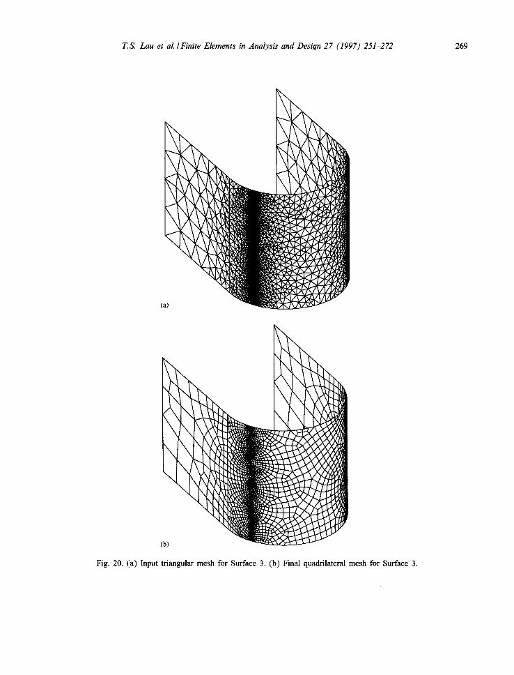
Totally four different curved surfaces, which consist of one or more subsurfaces, are given in this section as mesh generation examples. For all the surfaces tested, triangular meshes corresponding to different pre-defined node spacing functions were generated. These triangular meshes, together with the geometrical definitions of the surfaces, are then fed into the quadrilateral mesh conversion scheme as input for the formation of quadrilateral meshes. The exact analytical forms for these surfaces and the node spacing functions used will not be given here since they are very lengthy but not very informative. A much clearer picture of the performance of the present conversion scheme can be obtained by examining the characteristics of the input triangular and the final quadrilateral meshes which are listed in Tables 3(a) and (b) respectively. The input triangular meshes and the final quadrilateral mesh generated are shown in Figs. 18-21 (Figs. 18a-21a for the background triangular meshes and Figs. 18b-21b for the resulted quadrilateral meshes). From Table 3 and Figs. 18-21, by comparing corresponding triangular and quadrilateral meshes, one can see that the quadrilateral mesh conversion scheme is able to preserve both the grading and density of the background triangular meshes. It can be seen from Table 3 that the number of nodes of the final quadrilateral meshes generated are very similar to the corresponding input triangular meshes while the final number of quadrilaterals are approximately half o f the number of input triangles. Also, despite that the element size ratio in some meshes are quite large (>1000), the shape quality of the elements generated

T.S. Lau et al./Finite Elements in Analysis and Design 27 (1997) 251-272 267
(a)
(b)
Fig. 18. (a) Input triangular mesh for Surface 1. (b) Final quadrilateral mesh for Surface 1.
are well above the acceptable margin with very few elements with internal angles less than 30 ° or greater than 150 ° . Hence, it can be concluded that the proposed mesh conversion algorithm is capable to generate well graded quadrilateral meshes which are adequate representations o f the target surfaces as well as preserving the element size o f the input triangular meshes.

268 T.S. Lau et al./Finite Elements in Analysis and Design 27 (1997) 251-272
Fig. 19. (a) Input triangular mesh for Surface 2. (b) Final quadrilateral mesh for Surface 2.
T.S. Lau et al./Finite Elements in Analysis and Design 27 (1997) 251-272 269
Fig. 20. (a) Input triangular mesh for Surface 3. (b) Final quadrilateral mesh for Surface 3.

270 T.S. Lau et al./Finite Elements in Analysis and Design 27 (1997) 251-272
Fig. 21. (a) Input triangular mesh for Surface 4. (b) Final quadrilateral mesh for Surface 4.

T.S. Lau et al./Finite Elements in Analysis and Design 27 (1997) 251-272 271
5. Conclusion
In this paper, a fiJlly automatic indirect quadrilateral mesh generator using the systematic merging technique for the generation of quadrilateral meshes over surfaces is presented. By merging two triangular elements at a time for the formation of quadrilateral mesh, the element density and grading of the background mesh can be well preserved. As a result, by using a high-quality well-graded triangular mesh as the background mesh, an equally well graded, high-quality quadrilateral mesh can be generated over analytical curved surfaces in compliance with a given element density distribution. The input data required by the mesh generator are no more than the background triangular mesh and the geometrical definition of the analytical surface. Therefore, the current conversion scheme can be used in conjunction with most surface triangulators for the generation of adaptive refinement quadrilateral meshes for shell analysis.
Acknowledgement
The authors would like to thank for the financial support from the Research Grants Council for the project "Adaptive Refinement Finite Element Analysis for Three-dimensional Problems".
References
[1] D.A. Lavender, D.R. Hayhurst, An assessment of higher-order isoparametric elements for solving an elastic problem, Comput. Methods Appt. Mech. Eng. 56 (1986) 139-165.
[2] S.H. Lo, C.K. Lee, On using mesh of mixed element types in adaptive finite element analysis, Finite Elements Anal. Des. 11 (1992) 307-336.
[3] J.Z. Zhu, E. Hintorc, O.C. Zienkiewicz, Adaptive finite element analysis with quadrilaterals, Comput. Struct. 40 (1991) 1097-1104.
[4] E.N. Dvorkin, K.J. Bathe, A continuum mechanics based four-node shell element for general non-linear analysis, Eng. Comput. 1 (1984) 77-88.
[5] H.C. Huang, A new nine node degenerated shell element with enhanced membrane and shear interpolation, Int. J. Numer. Methods Eng. 22 (1986) 73-92.
[6] O.C. Zienkiewicz, R.L. Taylor, The Finite Element Method, Vol. 2: Solid and Fluid Mechanics, Dynamics and Nonlinearity, Ch. 21, 4th ed., McGraw-Hill, New York, 1989.
[7] O.C. Zienkiewicz, R.L. Taylor, P. Papadopoulos, E. Onate, Plate bending elements with discrete constraints: new triangular elements, Comput. Struct. 35 (1990) 505-522.
[8] O.C. Zienkiewicz, D.V. Phillips, An automatic mesh generation scheme for plane and curved surfaces by isoparametric coordinates, Int. J. Numer. Methods Eng. 3 (1971) 519-528.
[9] C. Chinnaswamy, ]3. Amadei, T.H. Illangasekare, A new method for finite element transitional mesh generation, Int. J. Numer. Methods Eng. 31 (1991) 1253-1270.
[10] R.H. Crawford, WN. Waggenspack, J. Anderson, D.C. Anderson, Composite mappings for planar mesh generation, Int. J. Numer. Methods Eng. 24 (1987) 2241-2252.
[11] L.C. Wellford, J. Gorman, M.R. Gorman, A finite element transition mesh generation procedure using sweeping functions, Int. J. Numer. Methods Eng. 26 (1988) 2623-2643.
[12] Y.C. Liu, H.A. Elmaraghy, K. Zhang, An expert system for forming quadrilateral finite elements, Eng. Comput. 7 (1990) 249-257.
[13] J.A. Talbert, A.R. Parkinson, Development of an automatic two-dimensional finite element mesh generator using quadrilateral elements and bezier curve boundary definition, Int. J. Numer. Methods Eng. 29 (1991) 1551-1567.

272 T.S. Lau et al./Finite Elements in Analysis and Design 27 (1997) 251-272
[14] T.D. Blacker, M.B. Stephenson, Paving: a new approach to automated quadrilateral mesh generation, Int. J. Numer. Methods Eng. 32 (1991) 811-847.
[15] S.H. Lo, Generating quadrilateral elements on plane and over curved surfaces, Comput. Struct. 31 (1989) 421-426. [16] C.K. Lee, S.H. Lo, A new scheme for the generation of a graded quadrilateral mesh, Comput. Struct. 52 (1994)
847-857. [17] B.P. Johnston, J.M. Sullivan, A. Kwasnik, Automatic conversion of triangular finite element meshes to quadrilateral
elements, Int. J. Numer. Methods Eng. 31 (1991) 67-84. [18] J.Z. Zhu, O.C. Zienkiewicz, E. Hinton, J. Wu, A new approach to the development of automatic quadrilateral mesh
generation, Int. J. Numer. Methods Eng. 32 (1991) 849-866. [19] J. Peraire, J. Peiro, K. Morgan, O.C. Zienkiewicz, Finite element mesh generation and adaptive procedure for CFD,
Proc. GAMNI/SMAI Conf. on automatic and adaptive mesh generation, Grenoble, France, 1-2 October, 1987. [20] T.S. Lau, S.H. Lo, Finite element mesh generation over analytical curved surfaces, Comput. Struct. 59 (1996) 301-
309. [21] T.S. Lau, Adaptive finite element analysis for shell structures, Ph.D. Thesis, The University of Hong Kong, 1995.