general mechanics - · pdf filegeneral mechanics stress analysis of adhesively ... composite,...
TRANSCRIPT

Journal of Theoretical and Applied Mechanics, Sofia, 2011, vol. 41, No. 2, pp. 3–20
GENERAL
MECHANICS
STRESS ANALYSIS OF ADHESIVELY BONDED AND
PINNED SINGLE LAP JOINTS USING THREE
DIMENSIONAL FINITE ELEMENT MODELS∗
Kemal Aldas, Faruk Sen, Hakan Palancıoglu
Aksaray University, Department of Mechanical Engineering,
68100, Aksaray, Turkey
e-mail:[email protected]
[Received 09 December 2010. Accepted 29 August 2011]
Abstract. In this study, stress analysis was carried out for adhesivelybonded and pinned single lap joints of aluminium thin sheets. For thispurpose, three dimensional finite element models have been created toobtain stress distributions based on, firstly, pinned boundary conditionwith tensile loading and then both pinned and applied uniform temper-ature conditions. The analyses were assumed using two aluminium thinmetal sheets bonded with epoxy adhesive and pinned. It was found thatthe positions of the improved both structural and thermal stresses wereconsiderably affected from existence of a pin hole and boundary condi-tions. Additionally, double loadings included tensile and thermally causedhigher stresses, if it is compared with single tensile loading.Key words: Thermal stress analysis; single lap joint; epoxy adhesive;stress analysis; hybrid joints.
1. Introduction
Adhesive bonding technology is frequently used nowadays in almost allthe industries fields of the world and this is mainly owing to its high strength-weight ratio, low cost and high efficiency [1]. Nonetheless, the design of safeand cost effective bonded joints is a main challenge. It forces the engineer tohave a good understanding of the effect of material and geometric parameterson the joint’s strength [2]. In fact, the adhesive joints experience not onlymechanical but also thermal loads. The thermal strains in the joint membersmight cause serious stresses [3], because the adhesive joints consist of materialswith different mechanical and thermal properties. For example, adhesive joints
*Corresponding author e-mail: [email protected]

4 K. Aldas, F. Sen, H. Palancıoglu
used in supersonic aircraft need to withstand low and high-temperatures, typ-ically from −55 ◦C (depending on altitude) to as much as 200 ◦C or more [4].Besides, most commonly, joints are created by using mechanical fasteners. Pinor bolt joints are unavoidable in complex structures because of their low cost,simplicity, and facilitation of disassembly for repair. It is significant, therefore,to determine the failure strength and failure modes of these pinned or boltedconnections [5]. The mechanical joint always requires fastener holes. Cuttingthe fastener holes creates local damage and stress concentration, and conse-quently, leads to a loss of structural strength. [6]. The transfer of load througha mechanical joint is by shear forces in the bolt and frictional forces developedat the interface between the joined plates [7]. Briefly, the most challengingproblem faced by a design engineer is the possible weakness of the adhesivebond and the poor through-thickness strength of the adherents. One promis-ing approach is to apply through-thickness reinforcement using small diametermetallic or fibrous pins [8].
Based on the literature, many researchers have studied either adhe-sively bonded or pinned single lap joint, double lap joint etc. The analysisof hybrid joints designed using both adhesively bonded and pinned single lapjoints under both thermal and tensile loads has not been investigated yet, ac-cording to authors’ knowledge. The transient thermal analysis of an adhesivelybonded and laser-spot welded joint was performed based on a thermal modeldeveloped for the laser-spot welding of multi-layered sheets using a pulsedNd:YAG laser. The material non-linear properties of adhesive and sheets inthe thermal stress analysis were considered using the non-linear finite elementmethod [9]. Nakano et al. [10] carried out a thermal stress analysis of an ad-hesive butt joint, which contained circular holes and rigid fillers in an adhesiveand was under a non-uniform temperature field. The adherents were assumedto be rigid and the adhesive was replaced with a finite strip having holes andrigid fillers in it and the thermal stress distribution in the adhesive was solvedusing a two-dimensional theory of elasticity. Morais et al. [11] investigatedthe strength of stainless-steel joints, bonded with two epoxy adhesives. Theexperimental programme included tests on single-lap and butt joints, as wellas thick-adherent and napkin ring shear tests. Nevertheless, FEM increaseddoubts on the true adhesive strengths, due to the complex stress state in jointtests and pressure-dependent adhesive performance. In spite of some worries,FEM illustrated that failure could be fairly well predicted by a maximum shearstrain criterion. Rastogi et al. [12] studied thermal stresses in aluminium-to-composite, symmetric, double-lap joints using FEM. The joint configurationconsidered aluminium adherent in combination with four different unidirec-

Stress Analysis of Adhesively Bonded and Pinned Single Lap. . . 5
tional laminated composite adherents subjected to uniform temperature load-ing. Silva and Adams [13] investigated a mixed adhesive joint. Experimentswere applied for titanium/titanium and titanium/composite double lap joints.It was shown that, for a joint with dissimilar adherents, the combination oftwo adhesives gave a better performance over the temperature range than ahigh temperature adhesive alone. Silva and Adams [4] were also studied foradhesive joints with dual adhesives to be used over a wide temperature rangetheoretically in a previous paper. For this purpose, a numerical analysis wasperformed using finite element models to obtain the stress distribution in amixed adhesive joint so as to find the best possible design of titanium/titaniumand titanium/composite double lap joints. The combination of two adhesivesgives a better performance over the temperature range considered than theuse of a high-temperature adhesive alone, too according to numerical analy-sis results, for a joint with dissimilar adherends. Grassi et al. [8] presenteda simple and effcient computational approach for analyzing the benefits ofthrough-thickness pins for restricting debond failure in joints. It is suggestedthat the resulting model can be used to path the evolution of competing fail-ure mechanisms, including tensile or compressive failure of the adherents, jointdebonding (creating leak, for example, if the joint is in a pipeline), and ulti-mate failure associated with pin rupture or pullout. In a previous study [14],Alda and Sen performed a three dimensional stress analysis of hybrid jointsusing different materials such as copper, steel and titanium. Hybrid joint wasdesigned both as adhesively bonded and pinned single lap joints. A uniformtemperature load as 45 ◦C was only performed on the half model. Accordingto results, steel adherents cause higher stresses than other used materials. Thetitanium adherents provided lower stresses.
In this study, stress analysis was performed for adhesively bonded andpinned single lap joints. Three dimensional finite element models have beendeveloped to obtain stress distributions based on, firstly, pinned boundarycondition with tensile loading and then with pinned condition and applieduniform temperature. The analyses were carried out using two aluminiumthin metal sheets bonded with epoxy adhesive and pinned.
Materials and methods
2.1. Problem Statement
In this work, a hybrid joint was assumed from both adhesive bondedand pinned joints of two thin aluminium sheets. The adhesive was preferredas epoxy resin, since it is used many real applications because of good bonding

6 K. Aldas, F. Sen, H. Palancıoglu
properties. Additionally, it is known that epoxies have excellent combina-tion of mechanical properties, corrosion resistance, dimensionally stable, goodadhesion, relatively inexpensive and good electrical properties [15]. Thin alu-minium sheets are preferred in air industry because of the low density accordingto other metal materials. Geometry and dimensions of modelled hybrid jointare shown in Fig. 1. The thickness of each aluminium adherent was 2 mm,
Fig. 1. The adhesively bonded and pinned single-lap joint
whereas the thickness of epoxy adhesive was 0.2 mm. However, the lengthsof each adherents and adhesive were 100 mm and 50 mm, respectively. Thewidth of both adherents and adhesive was 25 mm, since the problem was as-sumed as three dimensional one. Additionally pin diameter selected as 5 mm.In other words, both the edge distance-to-hole diameter ratio (E/D) and platewidth-to-hole diameter ratio (W/D) were considered as 5. The best E/D andW/D ratio were 5 for single pinned joints [16–17], since some previous studiespointed out. These ratios provide higher values of bearing strengths and bear-ing failure mode which is the desired failure mode get rid of catastrophic failureof pinned joints. Physical properties of aluminium thin sheets and epoxy ad-hesive are listed in Table 1 [9]. It is assumed, that material properties werenot changed depending on increasing values of applied uniform temperatures,since the analyses were not performed at higher temperatures.
Table 1. Physical properties of aluminum and epoxy adhesive
Property Aluminum Epoxy
Density, ρ (kg/m3) 2707 1264
Specific heat, cp (J/kgK) 896 1046
Thermal conductivity, k (W/mK) 204 0.179
Elasticity modulus, E (GPa) 66 3.3
Poisson’s ratio, υ 0.33 0.30
Thermal expansion coefficient, α (µm/m ◦C) 23.6 43.3

Stress Analysis of Adhesively Bonded and Pinned Single Lap. . . 7
The finite element method (FEM) was used to obtain stresses. Forthis purpose, ANSYS [18] software was chosen, since it is accepted as power-ful software for both scientific studies and commercial applications. SOLID45element type was preferred for the duration of the mesh generation process.The geometry, node locations, and the coordinate system for this element areshown in Fig. 2. SOLID45 element is used for the 3-D modelling of solid struc-
Fig. 2. SOLID45 element type [15]
tures. The element is defined by eight nodes having three degrees of freedomat each node: translations in the nodal x, y, and z directions. The element hasplasticity, creep, swelling, stress stiffening, large deflection, and large straincapabilities [19]. The FEM structure of the hybrid single-lap joint is shown inFig. 3 with detail illustrations. This figure point out that the good mappedmesh structure was developed on the model including pin hole zone, clearly.Mapped mesh structure for a good FEM solution, should be preferred becauseof some advantages comparing to the free mesh. Furthermore, a mapped meshis limited in terms of the element shape it contains and the pattern of the mesh[18-19]. As mentioned previously, the hole is needed if the pin, bolt, rivet etc.are used in the structure for mechanical joint. Therefore, mesh structure is veryimportant around the hole zone because of stress concentrations. Nonetheless,the generation of mapped mesh is very difficult if the model has hole. How-ever, in this study, the mapped mesh was provided by the author. Besides,the refine mesh was build up around the pin hole area and near areas becauseof the providing a good solution as seen in Detail C in Fig. 3. Elements innumber 34350 and 42290 nodes were created in the 3D-model after that in the

8 K. Aldas, F. Sen, H. Palancıoglu
Fig. 3. FEM model and mesh details of hybrid single-lap joint
meshing process,. Moreover, a half part of the whole hybrid joint structurewas modelled because of the symmetry of it. This advantage was supplied todecrease both element and node numbers and the solution time.
Solution process was completed in two stages. In first step, the pinnedcondition was carried out on the half model. For this purpose, when x = 0,free side of the lower adherent was fixed for all directions (Ux = Uy = Uz = 0).After that, a pressure was applied on free side of upper adherent as 10 MPa.The pinned condition was performed on the hole surfaces, too. As a result,the hybrid joint model was conditioned as under only tensile loading. In thesecond step, the uniform temperature load was applied on the half model with

Stress Analysis of Adhesively Bonded and Pinned Single Lap. . . 9
tensile loads. Since, in practice adhesive joints can suffer thermal loads as wellas structural loads, too. These thermal loads play an important role in thestrength of the adhesively bonded joint [20]. The reference temperature wasassumed to be 25 ◦C. The magnitude of applied uniform temperature was as55 ◦C. Briefly, in the second step, the solution for hybrid joint was performedunder both thermal and tensile loads.
2.2. Mathematical FormulationCartesian coordinates (x, y, z) are used for computation of stress. The
notations for stress components are σx, σy, σz and τxy. Strain displacementcan be expressed briefly by using finite element method, as follows [21—23],
(1) {ε} = [B] {δ}e ,
where [B] is the strain-displacement interpolation matrix and {δ}e is displace-ment vector for element (e). The stress-strain displacement relation for arotation symmetric element is defined as follows
(2) {σ} = [C] {ε} ,
where [C] is the elasticity matrix.Thermal stresses are calculated by using the principle of virtual work.
In this method, one considers infinitesimal small nodes displacements {δ}e
imposed onto body. This causes external total virtual work (this externalvirtual work is equal to the internal virtual work which is defined by stresses{σ} and strains {ε}e). Using integration over the volume of element,
(3) [δe]T {R}e =
∫V
{εe}T {σ} dV,
By using equations (1) and (2),
(4) {R}e =
∫V
[B]T [C] [B] dV
Here,
(5) [K]e =
∫V
[B]T [C] [B] dV
is the stiffness matrix of element “e”. The total stiffness matrix [K] is obtainedby assembling the stiffness matrix of all elements. Analogously to the equation(3) it can be written,
(6) {R} = [K] {δ} .

10 K. Aldas, F. Sen, H. Palancıoglu
The load vector {R} includes only thermal forces. One can obtain byusing the mean thermal expansion coefficient αm and temperature gradient{∆T}, the following:
(7) {R}T =
∫V
[B]T [C] [B] αm {∆T} dV.
The thermal force is integrated in the equation (4),
(8) {δ} = [K]−1 {R}T
and then the stresses can be obtained according to the following equation:
(9) {σ} = [C] [B] {ε} − [C] αm {∆T} .
3. Results and discussion
Node and path definitions are essential around the pin hole zone be-cause of the good evaluating. Since, stress concentrations are created on thisarea due to the existence of hole. Node definitions and paths are shown in Fig.4. According to this figure, four important paths are defined from θ = 0◦ toθ = 180◦. The path AB is defined on the top surface of the upper adherent.The Path CD is between upper adherent and adhesive layer. The Path EF isbetween adhesive layer and lower adherent. Lastly, the path GH is positionedon the bottom surface of the lower adherent.
Fig. 4. Node definitions for evaluating the results around pin hole

Stress Analysis of Adhesively Bonded and Pinned Single Lap. . . 11
(a) For x-direction
(b) For y-direction

12 K. Aldas, F. Sen, H. Palancıoglu
(c) Shear stresses
(d) von Mises stresses
Fig. 5. Stress distributions around pin hole on defined paths without thermal loads

Stress Analysis of Adhesively Bonded and Pinned Single Lap. . . 13
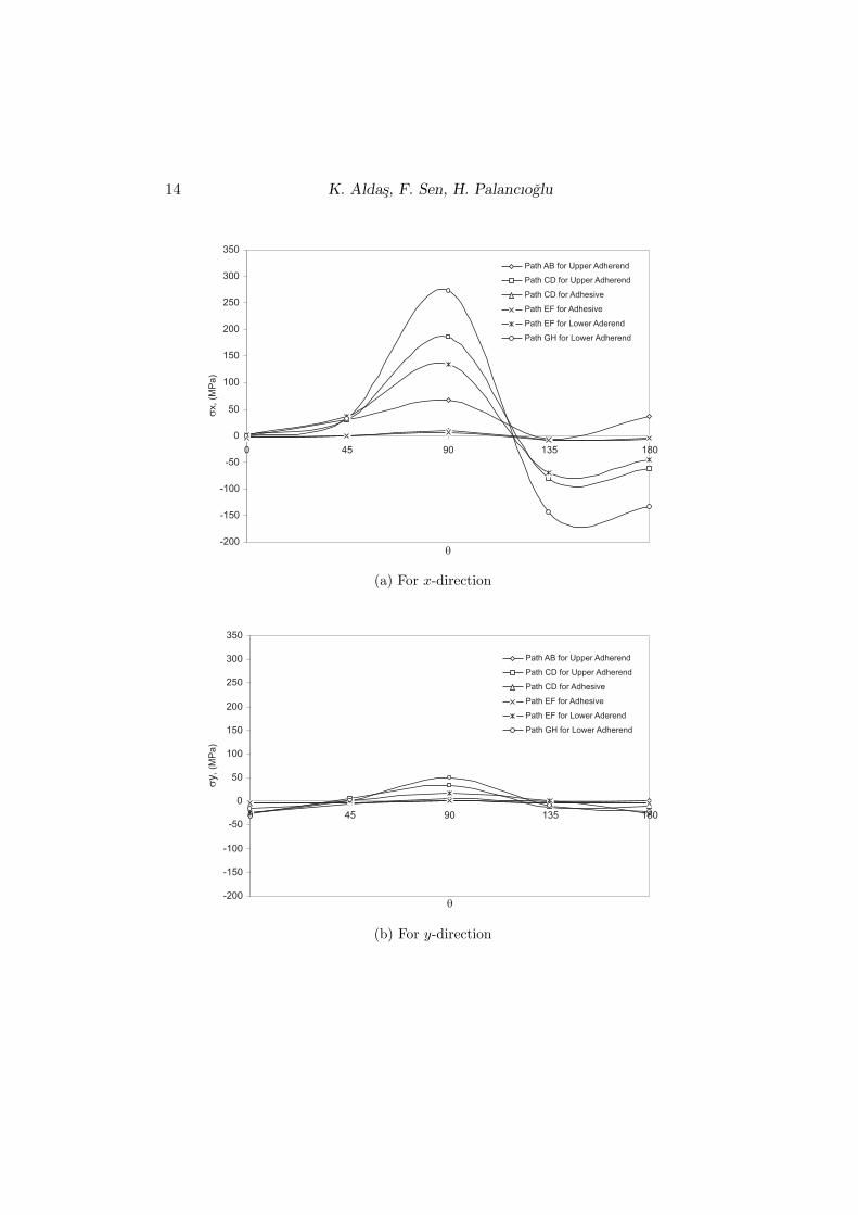
Stress distributions around pin hole on defined four paths without ther-mal loads are shown in Fig. 5. This figure points out that stresses for x-direc-tion (σx) are higher than y-direction. The magnitudes of stresses on adhesivelayer are much lower than aluminium sheets. The higher values of stresses areobtained for upper adherent and θ = 90◦. Besides, higher values of stresses foradhesive layer and lower adherent are also calculated for θ = 90◦. It means,that the failure starts from θ = 90◦ positioned nodes. It is appropriate, resultwith some previous studies for single pinned joints to be obtained experimen-tally [24–25]. The high stresses where θ = 90◦ are tensile form both for x andy-directions except Path GH. These tensile stresses are decreased after θ = 90◦
changed as compressive form between θ = 135◦ and θ = 180◦. It is also suit-able result, since this zone is pressed by the pin. The failure is occurred asbearing at this area [16–17, 24–25]. According to Fig. 5 shear stresses arealso very important. It is known, that shear stresses cause debonding betweenadhesive layer and adherent layers. Briefly, the highest values of stresses forpinned condition are calculated as 107.77 MPa for x-direction, 17.25 MPa fory-direction, 29.68 MPa for shear stresses and 120.20 MPa for von Mises stress.All of them occur at θ = 90◦ and their forms are tensile. Additionally, highervalue of stresses is computed on Path AB where is the top surface of the upperadherent.
As mentioned previously, the solution was completed in two stages.Therefore, stress distributions around pin hole on defined paths with thermalloads are illustrated in Fig. 6. First of all, the magnitudes of stresses are in-creased both aluminium sheets and adhesive with double loadings. The curvesof Fig. 6 are seeing as in the similar Fig. 5. There is an important differ-ence between these two figures. Since, stresses on Path GH are higher thanother paths. In other words, the higher stresses occur on the bottom surfaceof the lower adherent when thermal loads applied with tensile loads, whereasthe highest values of stresses under only tensile stresses are calculated on thetop surface of the upper adherent (path AB). The highest values of stresses forpinned and thermal double loading conditions are calculated as 272.51 MPa forx-direction, 50.44 MPa for y-direction, 95.36 MPa for shear stresses and 327.33MPa for von Mises stress on the bottom surface of the lower adherent whenθ = 90◦. It can be said, that uniform thermal loading increased all stressesthree times nearly. The reason of this result is the different thermal expansioncoefficients of the aluminium and epoxy adhesive.
The stress distribution on adhesive layer is very important for adhe-sively bonded joints. It is known that ANSYS software provides colour contoursfor each part of the joint. Therefore, stress distributions on adhesive layer with-
14 K. Aldas, F. Sen, H. Palancıoglu
(a) For x-direction
(b) For y-direction

Stress Analysis of Adhesively Bonded and Pinned Single Lap. . . 15
(c) Shear stresses
(d) von Mises stresses
Fig. 6. Stress distributions around pin hole on defined paths with thermal loads

16 K. Aldas, F. Sen, H. Palancıoglu
Fig. 7. Stress distributions on adhesive layer without thermal loads(all stresses in MPa)

Stress Analysis of Adhesively Bonded and Pinned Single Lap. . . 17
Fig. 8. Stress distributions on adhesive layer with thermal loads(all stresses in MPa)

18 K. Aldas, F. Sen, H. Palancıoglu
out thermal loads and thermal loads are plotted in Figs 7 and 8 using colourcontours, respectively. These figures indicate that the magnitudes of stressesare increased when thermal loads are applied. For example, the highest vonMises stress 4.153 MPa without thermal loads, while it is calculated as 17.70after thermal loading. This increasing is also valid for other stresses, which iscalculated in x, y and z-directions. It can be said that stresses are increasedthree times on adhesive layer with extra thermal loading, practically. Further-more, stresses occur as compressive zone which is pinned contact surface fromafter θ = 90◦ to θ = 180◦. Nonetheless, the highest tensile stresses is observedwhen θ = 90◦. It means that the net tension failure may occur when θ = 90◦,whereas the bearing failure may be created in between θ = 90◦ and θ = 180◦
zone. As mentioned previously for aluminium sheets, this result for adhesivelayer is also suitable with previous experimental studies. Another importantresult derived from Figs 7 and 8, the highest stresses both tensile loads anddouble loadings are obtained as tensile form, generally. The highest stress is−4.88 MPa as compressive form only for y-direction under double loads, whilethe highest tensile stress is calculated as 3.71 MPa (Fig. 8(b)).
4. Conclusions
In this study, a thermal stress analysis was carried out for adhesivelybonded and pinned single lap joint using 3D-FEM. According to analyses re-sults some important points can be concluded as; the thermal stress analysispointed out that the thermal and mechanical mismatches of the aluminiumadherents and epoxy adhesive created high stress concentrations. Stresses areconcentrated pin hole zone both adherents and adhesive because of the exis-tence of the pin hole. After double loading as thermal and tensile, the magni-tudes of stresses are increased as three times according to single tensile loading.When θ = 90◦, stresses are occured as tensile, after the θ = 90◦ to θ = 180◦
which is the pin contact surface stresses are observed as compressive. Ten-sile stresses may cause net-tension failure and compressive stresses may reasonbearing failure, so the observed stress distribution is suitable with previouslyexperimental studies. Stresses are increased after uniform thermal loadings,since the differences of the mechanical properties between adhesive and adher-ents cause this result. The thermal expansion coefficient is very important inthis increasing, particularly.

Stress Analysis of Adhesively Bonded and Pinned Single Lap. . . 19
REFEREN CES
[1] You, M., Z. M. Yan, X. L. Zheng, H. Z. Yu,. Z. Li. A Numerical andExperimental Study of Gap Length on Adhesively Bonded Aluminium Double-Lap Joint. International Journal of Adhesion and Adhesives, 27 (2007), 696–702.
[2] Derewonko, A., J. Godzimirski, K. Kosiuczenko, T. Niezgoda, A.
Kiczko. Strength Assessment of Adhesive-Bonded Joints. Computational Ma-
terials Science, (in Press).[3] Apalak, M. K., R. Gunes. On Non-linear Thermal Stresses in an Adhesively
Bonded Single Lap Joint.Computers and Structures, 80 (2002), 85–98.[4] Silva, L. F. M., R. D. Adams. Joint Strength Predictions for Adhesive Joints
to be used over a Wide Temperature Range. International Journal of Adhesion
and Adhesives, 27 (2007), 362–379.[5] Okutan, B., Z. Aslan, R Karakuzu. A Study of the Effects of Various
Geometric Parameters on the Failure Strength of Pin-loaded Woven-glass-fiberReinforced Epoxy Laminate. Composites Science and Technology, 61 (2001),1491–1497.
[6] Ahn, H. S., J. H. Kweon, J. H Choi. Failure of Unidirectional-woven Com-posite Laminated Pin-loaded Joints. Journal of Reinforced Plastics and Com-
posites, 24 (2005), 735–752.[7] Wu, T. J., H. T. Hahn. The Bearing Strength of e-Glass/vinyl-ester Com-
posites Fabricated by Vartm. Composites Science and Technology, 58 (1997),1519–1529.
[8] Grassi, M., B. Cox, X. Zhang. Simulation of Pin-reinforced Single-lap Com-posite Joints. Composites Science and Technology, 66 (2006), 1623–1638.
[9] Apalak, M. K., K Aldas,. F Sen. Thermal Non-linear Stresses in an Ad-hesively Bonded and Laser-Spot Welded Single-lap Joint During Laser-MetalInteraction. Journal of Materials Processing Technology, 142 (2003), 1–19.
[10] Nakano, Y., M. Katsuo, M. Kawawaki, et al. Two-dimensional ThermalStress Analysis in Adhesive Butt Joints Containing Hole Defects and RigidFillers in Adhesive under non-Uniform Temperature Field. Journal of Adhesion,65 (1998), 57–80.
[11] Morais, A.B., A.B. Pereira, J.P. Teixeira, N.C Cavaleiro. Strength ofEpoxy Adhesive-bonded Stainless-steel Joints. International Journal of Adhe-
sion and Adhesives, 27 (2007), 679–686.[12] Rastogi, N., S. R. Soni, A.Nagar. Thermal Stresses in Aluminium-to-
composite Double-lap Bonded Joints. Advances in Engineering Software, 29(1998), 273–281.
[13] Silva, L. F. M., R. D. Adams. Adhesive Joints at High and Low Tempera-tures using Similar and Dissimilar Adherents and Dual Adhesives. International
Journal of Adhesion and Adhesives, 27 (2007), 216–226.[14] Aldas, K., F. Sen. Stress Analysis of Hybrid Joints using Different Materials
via 3D-FEM. International Journal of Engineering & Applied Sciences, Vol.3,Issue 1 (2011), 90–101.

20 K. Aldas, F. Sen, H. Palancıoglu
[15] Callister, W. D. Materials Science and Engineering and Introduction, USA,John Wiley & Sons Inc., 2003.
[16] Sayman, O., R. Siyahkoc, F. Sen, R. Ozcan. Experimental Determinationof Bearing Strength in Fiber Reinforced Laminated Composite Bolted-jointsunder Preload. Journal of Reinforced Plastics and Composites, 26 (2007), 1051–1063.
[17] Pakdil, M., F. Sen, O. Sayman, S. Benli. The Effect of Preload on FailureResponse of Glass-epoxy Laminated Composite Bolted-joints with Clearance.Journal of Reinforced Plastics and Composites, 26 (2007), 1239–1252.
[18] ANSYS, Release 10.0 Documentation, USA, Houston, PA, Swanson AnalysisSystem Inc.
[19] Moaveni, S. Finite Element Analysis: Theory and Application with ANSYS,USA, New Jersey, Pearson Education Inc., 2003.
[20] Apalak, M. K., R. Gunes, S. Eroglu. Thermal Residual Stresses in anAdhesively Bonded Functionally Graded Tubular Single Lap Joint. International
Journal of Adhesion and Adhesives, 27 (2007), 26–48.
[21] Huebner, K. H., E. A. Thornton. The Finite Element for Engineers, NewYork, Wiley, 1982.
[22] Taymaz, I., A Mimaroglu,. E. Avci, V. UcaR, M. Gur. Comparison ofThermal Stresses developed in Al2O3–SG, ZrO2–(12% Si + Al) and ZrO2–SGThermal Barrier Coating Systems with NiAl, NiCrAlY and NiCoCrAlY Inter-layer Materials Subjected to Thermal Loading, Surface and Coatings Technol-ogy, 1999, 116–119, 690–693.
[23] Sen, F., O. Sayman, M. Toparli, E. Celik. Stress Analysis of High Tem-perature ZrO2 Insulation Coatings on Ag using Finite Element Method. Journal
of Materials Processing Technology, 180/1–3 (2006), 239–245.
[24] Sen, F., M. Pakdil, O. Sayman, S. Benli. Experimental Failure Analysisof Mechanically Fastened Joints with Clearance in Composite Laminates underPreload. Materials & Design, 29 (2008), 1159–1169.
[25] Sen, F., O. Sayman, R. Ozcan, R. Siyahkoc. The Failure Response of SingleBolted Composite Joints under Various Preload. Indian Journal of Engineering
& Materials Sciences, 17 (2010), 39–48.