general information gi
TRANSCRIPT

GENERAL INFORMATION
C
D
E
B
GI
SECTION GI
GENERAL INFORMATIONF
G
H
I
J
K
L
M
N
O
P
CONTENTS
REGULAR GRADE
HOW TO USE THIS MANUAL ...................... 3
HOW TO USE THIS MANUAL ............................ 3Description ................................................................3Terms ........................................................................3Units ..........................................................................3Contents ....................................................................3Relation between Illustrations and Descriptions .......4Components ..............................................................4
HOW TO FOLLOW TROUBLE DIAGNOSES ..... 6Description ................................................................6How to Follow Test Groups in Trouble Diagnosis ......6Key to Symbols Signifying Measurements or Pro-cedures .....................................................................7
HOW TO READ WIRING DIAGRAMS ................ 9Connector Symbols ...................................................9Sample/Wiring Diagram -Example- .........................10Description ..............................................................11
ABBREVIATIONS ..............................................13Abbreviation List ......................................................13
TIGHTENING TORQUE OF STANDARD BOLTS ................................................................14
Description ..............................................................14Tightening Torque Table (New Standard Includ-ed) ...........................................................................14
RECOMMENDED CHEMICAL PRODUCTS AND SEALANTS ................................................17
Recommended Chemical Products and Sealants ....17
VEHICLE INFORMATION ............................18
IDENTIFICATION INFORMATION .....................18Model Variation .......................................................18Information About Identification or Model Code ......18Dimensions .............................................................20
Wheels & Tires ........................................................20
PRECAUTION ..............................................21
PRECAUTIONS .................................................21Description ...............................................................21Precaution for Supplemental Restraint System (SRS) "AIR BAG" and "SEAT BELT PRE-TEN-SIONER" .................................................................21Precaution Necessary for Steering Wheel Rota-tion after Battery Disconnect ...................................21Precaution for Procedure without Cowl Top Cover ....22General Precautions ................................................22Three Way Catalyst .................................................23Multiport Fuel Injection System or Engine Control System .....................................................................24Hoses ......................................................................24Engine Oils ..............................................................25Air Conditioning .......................................................25Fuel ..........................................................................25
LIFTING POINT .................................................26Commercial Service Tools .......................................26Garage Jack and Safety Stand and 2-Pole Lift .......26Board-On Lift ...........................................................27
TOW TRUCK TOWING .....................................28Tow Truck Towing ...................................................28Vehicle Recovery (Freeing a Stuck Vehicle) ...........28
BASIC INSPECTION ...................................30
SERVICE INFORMATION FOR ELECTRICAL INCIDENT ..........................................................30
Work Flow ................................................................30Control Units and Electrical Parts ............................30How to Check Terminal ...........................................31Intermittent Incident .................................................34Circuit Inspection .....................................................37
CONSULT-III/GST CHECKING SYSTEM .........42Description ...............................................................42
GI-1Revision: 2009 March 2009 Z12

CONSULT-III Function and System Application*1 ... 42CONSULT-III/GST Data Link Connector (DLC) Circuit ..................................................................... 42Wiring Diagram - CONSULT-III/GST CHECKING SYSTEM - ............................................................... 44
INSPECTION AND ADJUSTMENT ................... 47
ADDITIONAL SERVICE WHEN REMOVING BAT-TERY NEGATIVE TERMINAL .................................. 47
ADDITIONAL SERVICE WHEN REMOVING BATTERY NEGATIVE TERMINAL : Required Procedure After Battery Disconnection .................. 47
Krom
VEHICLE INFORMATION .......................... 48
DIMENSIONS AND WEIGHTS .......................... 48Dimensions and Weights ........................................ 48
PRECAUTION ............................................ 49
LIFTING POINT ................................................. 49Lifting Point ............................................................. 49
TOW TRUCK TOWING ..................................... 50Tow Truck Towing ................................................... 50Vehicle Recovery (Freeing a Stuck Vehicle) ........... 50
GI-2Revision: 2009 March 2009 Z12

HOW TO USE THIS MANUAL[REGULAR GRADE]
C
D
E
F
G
H
I
J
K
L
M
B
I
N
O
P
< HOW TO USE THIS MANUAL >
GHOW TO USE THIS MANUALHOW TO USE THIS MANUAL
Description INFOID:0000000004992449
This volume explains “Removal, Disassembly, Installation, Inspection and Adjustment” and “Trouble Diag-noses”.
Terms INFOID:0000000004992450
• The captions WARNING and CAUTION warn you of steps that must be followed to prevent personal injuryand/or damage to some part of the vehicle.WARNING indicates the possibility of personal injury if instructions are not followed.CAUTION indicates the possibility of component damage if instructions are not followed.BOLD TYPED STATEMENTS except WARNING and CAUTION give you helpful information.Standard value: Tolerance at inspection and adjustment.Limit value: The maximum or minimum limit value that should not be exceeded at inspection and adjust-ment.
Units INFOID:0000000004992451
• The UNITS given in this manual are primarily expressed as the SI UNIT (International System of Unit), andalternatively expressed in the metric system and in the yard/pound system.Also with regard to tightening torque of bolts and nuts, there are descriptions both about range and about thestandard tightening torque.
“Example”Range
Standard
Contents INFOID:0000000004992452
• A QUICK REFERENCE INDEX, a black tab (e.g. ) is provided on the first page. You can quickly find thefirst page of each section by matching it to the section's black tab.
• THE CONTENTS are listed on the first page of each section.• THE TITLE is indicated on the upper portion of each page and shows the part or system.• THE PAGE NUMBER of each section consists of two or three letters which designate the particular section
and a number (e.g. “BR-5”).• THE SMALL ILLUSTRATIONS show the important steps such as inspection, use of special tools, knacks of
work and hidden or tricky steps which are not shown in the previous large illustrations.Assembly, inspection and adjustment procedures for the complicated units such as the automatic transaxleor transmission, etc. are presented in a step-by-step format where necessary.
Outer Socket Lock Nut : 59 - 78 N·m (6.0 - 8.0 kg-m, 43 - 58 ft-lb)
Drive Shaft Installation Bolt : 44.3 N·m (4.5 kg-m, 33 ft-lb)
GI-3Revision: 2009 March 2009 Z12

[REGULAR GRADE]HOW TO USE THIS MANUAL
< HOW TO USE THIS MANUAL >
Relation between Illustrations and Descriptions INFOID:0000000004992453
The following sample explains the relationship between the part description in an illustration, the part name inthe text and the service procedures.
Components INFOID:0000000004992454
• THE LARGE ILLUSTRATIONS are exploded views (see the following) and contain tightening torques, lubri-cation points, section number of the PARTS CATALOG (e.g. SEC. 440) and other information necessary toperform repairs.The illustrations should be used in reference to service matters only. When ordering parts, refer to the appro-priate PARTS CATALOG.Components shown in an illustration may be identified by a circled number. When this style of illustration isused, the text description of the components will follow the illustration.
SAIA0519E
GI-4Revision: 2009 March 2009 Z12

HOW TO USE THIS MANUAL[REGULAR GRADE]
C
D
E
F
G
H
I
J
K
L
M
B
I
N
O
P
< HOW TO USE THIS MANUAL >
G
SYMBOLS
1. Union bolt 2. Copper washer 3. Brake hose
4. Cap 5. Bleed valve 6. Sliding pin bolt
7. Piston seal 8. Piston 9. Piston boot
10. Cylinder body 11. Sliding pin 12. Torque member mounting bolt
13. Washer 14. Sliding pin boot 15. Bushing
16. Torque member 17. Inner shim cover 18. Inner shim
19. Inner pad 20. Pad retainer 21. Pad wear sensor
22. Outer pad 23. Outer shim 24. Outer shim cover
1: PBC (Poly Butyl Cuprysil) grease or silicone-based grease
2: Rubber grease : Brake fluid
Refer to GI section for additional symbol definitions.
SFIA2959E
SAIA0749E
GI-5Revision: 2009 March 2009 Z12

[REGULAR GRADE]HOW TO FOLLOW TROUBLE DIAGNOSES
< HOW TO USE THIS MANUAL >
HOW TO FOLLOW TROUBLE DIAGNOSES
Description INFOID:0000000004992455
NOTICE:Trouble diagnoses indicate work procedures required to diagnose problems effectively. Observe the followinginstructions before diagnosing.• Before performing trouble diagnoses, read the “Work Flow” in each section.• After repairs, re-check that the problem has been completely eliminated.• Refer to Component Parts and Harness Connector Location for the Systems described in each section for
identification/location of components and harness connectors.• When checking circuit continuity, ignition switch should be OFF.• Refer to the Circuit Diagram for quick pinpoint check.
If you need to check circuit continuity between harness connectors in more detail, such as when a sub-har-ness is used, refer to Wiring Diagram in each individual section and Harness Layout in PG section for identi-fication of harness connectors.
• Before checking voltage at connectors, check battery voltage.• After accomplishing the Diagnosis Procedures and Electrical Components Inspection, check that all harness
connectors are reconnected as they were.
How to Follow Test Groups in Trouble Diagnosis INFOID:0000000004992456
1. Test group number and test group title• Test group number and test group title are shown in the upper portion of each test group.
2. Work and diagnosis procedure• Start to diagnose a problem using procedures indicated in enclosed test groups.
3. Questions and results• Questions and required results are indicated in test group.
4. Action• Next action for each test group is indicated based on result of each question.
JPAIA0021GB
GI-6Revision: 2009 March 2009 Z12

HOW TO FOLLOW TROUBLE DIAGNOSES[REGULAR GRADE]
C
D
E
F
G
H
I
J
K
L
M
B
I
N
O
P
< HOW TO USE THIS MANUAL >
GKey to Symbols Signifying Measurements or Procedures INFOID:0000000004992457
JPAIA0397GB
GI-7Revision: 2009 March 2009 Z12

[REGULAR GRADE]HOW TO FOLLOW TROUBLE DIAGNOSES
< HOW TO USE THIS MANUAL >
JPAIA0398GB
GI-8Revision: 2009 March 2009 Z12

HOW TO READ WIRING DIAGRAMS[REGULAR GRADE]
C
D
E
F
G
H
I
J
K
L
M
B
I
N
O
P
< HOW TO USE THIS MANUAL >
GHOW TO READ WIRING DIAGRAMS
Connector Symbols INFOID:0000000004992458
Most of connector symbols in wiring diagrams are shown from the terminal side.• Connector symbols shown from the terminal side are enclosed by
a single line and followed by the direction mark.• Connector symbols shown from the harness side are enclosed by
a double line and followed by the direction mark.• Certain systems and components, especially those related to
OBD, may use a new style slide-locking type harness connector.For description and how to disconnect, refer to PG section,“Description”, “HARNESS CONNECTOR”.
• Male and female terminalsConnector guides for male terminals are shown in black andfemale terminals in white in wiring diagrams.
SAIA0257E
SGI363
GI-9Revision: 2009 March 2009 Z12
[REGULAR GRADE]HOW TO READ WIRING DIAGRAMS
< HOW TO USE THIS MANUAL >
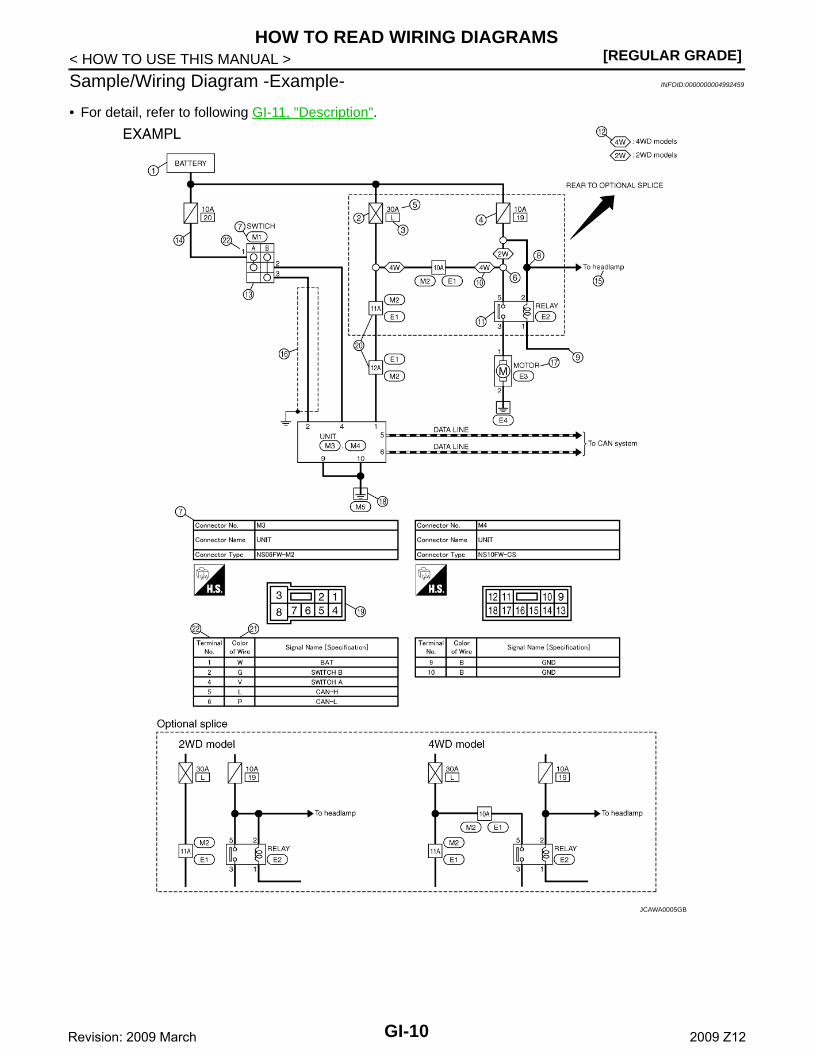
Sample/Wiring Diagram -Example- INFOID:0000000004992459
• For detail, refer to following GI-11, "Description".
JCAWA0005GB
GI-10Revision: 2009 March 2009 Z12

HOW TO READ WIRING DIAGRAMS[REGULAR GRADE]
C
D
E
F
G
H
I
J
K
L
M
B
I
N
O
P
< HOW TO USE THIS MANUAL >
GDescription INFOID:0000000004992460
SWITCH POSITIONS Switches are shown in wiring diagrams as if the vehicle is in the “normal” condition.A vehicle is in the “normal” condition when:
Number Item Description
1 Power supply • This means the power supply of fusible link or fuse.
2 Fusible link • “X” means the fusible link.
3Number of fusible link/fuse
• This means the number of fusible link or fuse location.
4 Fuse • “/” means the fuse.
5Current rating of fus-ible link/fuse
• This means the current rating of the fusible link or fuse.
6 Optional splice • The open circle shows that the splice is optional depending on vehicle application.
7 Connector number• The letter shows which harness the connector is located in.• Example “M”: main harness. For detail and to locate the connector, refer to PG-71, "How
To Read Harness Layout", PG-73, "Main Harness".
8 Splice • The shaded circle “ ” means the splice.
9 Page crossing • This circuit continues to an adjacent page.
10 Option abbreviation • This means the vehicle specifications which layouts the circuit between “ ”.
11 Relay • This shows an internal representation of the relay.
12 Option description • This shows a description of the option abbreviation used on the page.
13 Switch• This shows that continuity exists between terminals 1 and 2 when the switch is in the A
position. Continuity exists between terminals 1 and 3 when the switch is in the B position.
14 Circuit (Wiring) • This means the wiring.
15 System branch • This shows that the circuit is branched to other systems.
16 Shielded line • The line enclosed by broken line circle shows shield wire.
17 Component name • This shows the name of a component.
18 Ground (GND) • This shows the ground connection.
19 Connector• This means the connector information.• This unit-side is described by the connector symbols.
20 Connectors • This means that a transmission line bypasses two connectors or more.
21 Wire color
• This shows a code for the color of the wire.
B = BlackW = WhiteR = RedG = GreenL = BlueY = YellowLG = Light Green
BR = BrownOR or O = OrangeP = PinkPU or V (Violet) = PurpleGY or GR = GraySB = Sky BlueCH = Dark BrownDG = Dark Green
• When the wire color is striped, the base color is given first, followed by the stripe color as shown below:Example: L/W = Blue with White Stripe
22 Terminal number • This means the terminal number of a connector.
GI-11Revision: 2009 March 2009 Z12

[REGULAR GRADE]HOW TO READ WIRING DIAGRAMS
< HOW TO USE THIS MANUAL >• ignition switch is “OFF”,• doors, hood and trunk lid/back door are closed,• pedals are not depressed, and• parking brake is released.
MULTIPLE SWITCHThe continuity of multiple switch is described in two ways as shown below.• The switch chart is used in schematic diagrams.• The switch diagram is used in wiring diagrams.
SGI860
JSAIA0017GB
GI-12Revision: 2009 March 2009 Z12

ABBREVIATIONS[REGULAR GRADE]
C
D
E
F
G
H
I
J
K
L
M
B
I
N
O
P
< HOW TO USE THIS MANUAL >
GABBREVIATIONS
Abbreviation List INFOID:0000000004992461
The following ABBREVIATIONS are used:
ABBREVIATION DESCRIPTION
A/C Air Conditioner
A/T Automatic Transaxle/Transmission
ATF Automatic Transmission Fluid
D1 Drive range first gear
D2 Drive range second gear
D3 Drive range third gear
D4 Drive range fourth gear
FR, RR Front, Rear
LH, RH Left-Hand, Right-Hand
M/T Manual Transaxle/Transmission
OD Overdrive
P/S Power Steering
SAE Society of Automotive Engineers, Inc.
SDS Service Data and Specifications
SST Special Service Tools
2WD 2-Wheel Drive
22 2nd range second gear
21 2nd range first gear
12 1st range second gear
11 1st range first gear
GI-13Revision: 2009 March 2009 Z12

[REGULAR GRADE]TIGHTENING TORQUE OF STANDARD BOLTS
< HOW TO USE THIS MANUAL >
TIGHTENING TORQUE OF STANDARD BOLTS
Description INFOID:0000000004992462
This vehicle has both new standard based on ISO* and previous standard bolts/nuts. There are some differ-ences between these two types of bolts/ nuts; shape of the head, grade of strength, hexagonal width acrossflats and the standard tightening torque.• For guidance in discriminating, refer to GI-14, "Tightening Torque Table (New Standard Included)".• The new standard machine screws and tapping screws have a head of ISO standard torx recess.• If the tightening torque is not described in the description or figure, refer to GI-14, "Tightening Torque Table
(New Standard Included)".*ISO: International Organization for Standardization
Tightening Torque Table (New Standard Included) INFOID:0000000004992463
CAUTION:• The special parts are excluded.• The bolts/nuts in these tables have a strength (discrimination) number/symbol assigned to the head
or the like. As to the relation between the strength grade in these tables and the strength (discrimi-nation) number/symbol, refer to “DISCRIMINATION OF BOLTS AND NUTS”.
PREVIOUS STANDARD
CAUTION:
Grade (Strength
grade)
Bolt size
Bolt di-ameter
mm
Hexagonal width
across flatsmm
Pitchmm
Tightening torque (Without lubricant)
Hexagon head bolt Hexagon flange bolt
N·m kg-m ft-lb in-lb N·m kg-m ft-lb in-lb
4T
M6 6.0 10 1.0 5.5 0.56 4 49 7 0.71 5 62
M8 8.0 121.25 13.5 1.4 10 — 17 1.7 13 —
1.0 13.5 1.4 10 — 17 1.7 13 —
M10 10.0 141.5 28 2.9 21 — 35 3.6 26 —
1.25 28 2.9 21 — 35 3.6 26 —
M12 12.0 171.75 45 4.6 33 — 55 5.6 41 —
1.25 45 4.6 33 — 65 6.6 48 —
M14 14.0 19 1.5 80 8.2 59 — 100 10 74 —
7T
M6 6.0 10 1.0 9 0.92 7 80 11 1.1 8 97
M8 8.0 121.25 22 2.2 16 — 28 2.9 21 —
1.0 22 2.2 16 — 28 2.9 21 —
M10 10.0 141.5 45 4.6 33 — 55 5.6 41 —
1.25 45 4.6 33 — 55 5.6 41 —
M12 12.0 171.75 80 8.2 59 — 100 10 74 —
1.25 80 8.2 59 — 100 10 74 —
M14 14.0 19 1.5 130 13 96 — 170 17 125 —
9T
M6 6.0 10 1.0 11 1.1 8 — 13.5 1.4 10 —
M8 8.0 121.25 28 2.9 21 — 35 3.6 26 —
1.0 28 2.9 21 — 35 3.6 26 —
M10 10.0 141.5 55 5.6 41 — 80 8.2 59 —
1.25 55 5.6 41 — 80 8.2 59 —
M12 12.0 171.75 100 10 74 — 130 13 96 —
1.25 100 10 74 — 130 13 96 —
M14 14.0 19 1.5 170 17 125 — 210 21 155 —
GI-14Revision: 2009 March 2009 Z12

TIGHTENING TORQUE OF STANDARD BOLTS[REGULAR GRADE]
C
D
E
F
G
H
I
J
K
L
M
B
I
N
O
P
< HOW TO USE THIS MANUAL >
GThe parts with aluminum or the cast iron washer surface/thread surface are excluded.
NEW STANDARD BASED ON ISO
CAUTION:1. Use tightening torque with lubricant for the new standard bolts/nuts in principle. Friction coeffi-
cient stabilizer is applied to the new standard bolts/nuts.2. However, use tightening torque without lubricant for the following cases. Friction coefficient stabi-
lizer is not applied to the following bolts/nuts.- Grade 4.8, M6 size bolt, Conical spring washer installed- Paint removing nut (Size M6 and M8) for fixing with weld bolt
Grade (Strength
grade)
Bolt size
Bolt di-ameter
mm
Hexagonal width
across flatsmm
Pitchmm
Tightening torque
Hexagon head bolt Hexagon flange bolt
N·m kg-m ft-lb in-lb N·m kg-m ft-lb in-lb
4.8(Without lubricant)
M6 6.0 10 1.0 5.5 0.56 4 49 7 0.71 5 62
M8 8.0 131.25 13.5 1.4 10 — 17 1.7 13 —
1.0 13.5 1.4 10 — 17 1.7 13 —
M10 10.0 161.5 28 2.9 21 — 35 3.6 26 —
1.25 28 2.9 21 — 35 3.6 26 —
M12 12.0 181.75 45 4.6 33 — 55 5.6 41 —
1.25 45 4.6 33 — 65 6.6 48 —
M14 14.0 21 1.5 80 8.2 59 — 100 10 74 —
4.8(With lu-bricant)
M6 6.0 10 1.0 4 0.41 3 35 5.5 0.56 4 49
M8 8.0 131.25 11 1.1 8 — 13.5 1.4 10 —
1.0 11 1.1 8 — 13.5 1.4 10 —
M10 10.0 161.5 22 2.2 16 — 28 2.9 21 —
1.25 22 2.2 16 — 28 2.9 21 —
M12 12.0 181.75 35 3.6 26 — 45 4.6 33 —
1.25 35 3.6 26 — 45 4.6 33 —
M14 14.0 21 1.5 65 6.6 48 — 80 8.2 59 —
8.8(With lu-bricant)
M6 6.0 10 1.0 8 0.82 6 71 10 1.0 7 89
M8 8.0 131.25 21 2.1 15 — 25 2.6 18 —
1.0 21 2.1 15 — 25 2.6 18 —
M10 10.0 161.5 40 4.1 30 — 50 5.1 37 —
1.25 40 4.1 30 — 50 5.1 37 —
M12 12.0 181.75 70 7.1 52 — 85 8.7 63 —
1.25 70 7.1 52 — 85 8.7 63 —
M14 14.0 21 1.5 120 12 89 — 140 14 103 —
10.9(With lu-bricant)
M6 6.0 10 1.0 10 1.0 7 89 12 1.2 9 106
M8 8.0 131.25 27 2.8 20 — 32 3.3 24 —
1.0 27 2.8 20 — 32 3.3 24 —
M10 10.0 161.5 55 5.6 41 — 65 6.6 48 —
1.25 55 5.6 41 — 65 6.6 48 —
M12 12.0 181.75 95 9.7 70 — 110 11 81 —
1.25 95 9.7 70 — 110 11 81 —
M14 14.0 21 1.5 160 16 118 — 180 18 133 —
GI-15Revision: 2009 March 2009 Z12

[REGULAR GRADE]TIGHTENING TORQUE OF STANDARD BOLTS
< HOW TO USE THIS MANUAL >
DISCRIMINATION OF BOLTS AND NUTS
SAIA0453E
GI-16Revision: 2009 March 2009 Z12

RECOMMENDED CHEMICAL PRODUCTS AND SEALANTS[REGULAR GRADE]
C
D
E
F
G
H
I
J
K
L
M
B
I
N
O
P
< HOW TO USE THIS MANUAL >
GRECOMMENDED CHEMICAL PRODUCTS AND SEALANTS
Recommended Chemical Products and Sealants INFOID:0000000004992464
Refer to the following chart for help in selecting the appropriate chemical product or sealant.
Product Description PurposeNissan North America
Part No. (USA)Nissan Canada Part
No. (Canada)Aftermarket Cross-reference Part Nos.
1Rear View Mirror Adhe-sive
Used to permanently re-mount rear view mirrors to windows.
999MP-AM000P 99998-50505 Permatex 81844
2Anaerobic Liquid Gas-ket
For metal-to-metal flange sealing.Can fill a 0.38 mm (0.015 inch) gap and provide in-stant sealing for most pow-ertrain applications.
999MP-AM001P 99998-50503Permatex 51813 and 51817
3High Performance Thread Sealant
Provides instant sealing on any threaded straight or parallel threaded fitting. (Thread sealant only, no locking ability.)• Do not use on plastic.
999MP-AM002P 999MP-AM002P Permatex 56521
4 Silicone RTV
Gasket Maker999MP-AM003P(Ultra Grey)
99998-50506(Ultra Grey)
Permatex Ultra Grey 82194:Three Bond 1207,1215, 1216, 1217F, 1217G and 1217HNissan RTV Part No. 999MP-A7007
Gasket Maker for Maxima/Quest 5-speed automatic transmission(RE5F22A)
– –Three Bond 1281B or exact equivalent in its quality
5High Temperature, High Strength Thread Locking Sealant (Red)
Threadlocker 999MP-AM004P 999MP-AM004P
Permatex 27200:Three Bond 1360, 1360N, 1305 N&P, 1307N, 1335, 1335B, 1363B, 1377C, 1386B, D&E and 1388Loctite 648
6Medium Strength Thread Locking Seal-ant (Blue)
Threadlocker (service tool removable)
999MP-AM005P 999MP-AM005P
Permatex 24200, 24206, 24240, 24283 and 09178:Three Bond 1322, 1322N, 1324 D&N, 1333D, 1361C, 1364D, 1370C and 1374
GI-17Revision: 2009 March 2009 Z12

[REGULAR GRADE]IDENTIFICATION INFORMATION
< VEHICLE INFORMATION >
VEHICLE INFORMATIONIDENTIFICATION INFORMATION
Model Variation INFOID:0000000004992466
Model variation code (Prefix and suffix designations)
Information About Identification or Model Code INFOID:0000000004992467
IDENTIFICATION NUMBER
Destination Body Engine Transmission Axle Grade Model
Federal
5−door wagon MR18DE
6M/T
2WD
STD TDSALCY-EUA
MIDTDSALDY-EUA
CVTTDSALDZ-EUA
UPPER TDSALGZ-EUA
Canada
6M/TMID
TDSALDY-ENA
CVTTDSALDZ-ENA
UPPER TDSALGZ-ENA
JPAIA0580GB
JPAIA0591ZZ
GI-18Revision: 2009 March 2009 Z12

IDENTIFICATION INFORMATION[REGULAR GRADE]
C
D
E
F
G
H
I
J
K
L
M
B
I
N
O
P
< VEHICLE INFORMATION >
G
VEHICLE IDENTIFICATION NUMBER ARRANGEMENT
IDENTIFICATION PLATE
ENGINE SERIAL NUMBER
AUTOMATIC TRANSMISSION NUMBER
1. Vehicle identification plate 2. Emission control information label 3. Vehicle identification number (Chassis number)
4. Vehicle identification number plate 5. Air conditioner specification label 6. Tire and loading information label
7. FMVSS certification label
JPAIA0581GB
JPAIA0004ZZ
1. Type 2. Vehicle identification number (Chassis number) 3. Model variation code
4. Body color code 5. Trim color code 6. Engine model
7. Engine displacement 8. Transmission model 9. Axle model
: Vehicle front
SAIA1341E
GI-19Revision: 2009 March 2009 Z12

[REGULAR GRADE]IDENTIFICATION INFORMATION
< VEHICLE INFORMATION >
MANUAL TRANSAXLE NUMBER
Dimensions INFOID:0000000004992468
Unit: mm (in)
Wheels & Tires INFOID:0000000004992470
: Vehicle front
JPAIA0448ZZ
: Vehicle front
SAIA1338E
Overall length 3,980 (156.7)
Overall width 1,695 (66.7)
Overall height 1,650 (65.0)
Front tread 1,475 (58.1)
Rear tread 1,480 (58.3)
Wheelbase 2,530 (99.6)
Application Conventional Spare
Road wheel/offset mm (in)15 × 6J Steel/42 (1.65)
16 × 6J Alminum/42 (1.65)15 × 4T Steel/35 (1.38)
Tire sizeP195/60R15 87HP195/55R16 86V
T125/70D15 95M
GI-20Revision: 2009 March 2009 Z12

PRECAUTIONS[REGULAR GRADE]
C
D
E
F
G
H
I
J
K
L
M
B
I
N
O
P
< PRECAUTION >
GPRECAUTIONPRECAUTIONS
Description INFOID:0000000004992471
Observe the following precautions to ensure safe and proper servicing. These precautions are notdescribed in each individual section.
Precaution for Supplemental Restraint System (SRS) "AIR BAG" and "SEAT BELT PRE-TENSIONER" INFOID:0000000005144719
The Supplemental Restraint System such as “AIR BAG” and “SEAT BELT PRE-TENSIONER”, used alongwith a front seat belt, helps to reduce the risk or severity of injury to the driver and front passenger for certaintypes of collision. This system includes seat belt switch inputs and dual stage front air bag modules. The SRSsystem uses the seat belt switches to determine the front air bag deployment, and may only deploy one frontair bag, depending on the severity of a collision and whether the front occupants are belted or unbelted.Information necessary to service the system safely is included in the “SRS AIR BAG” and “SEAT BELT” of thisService Manual.WARNING:• To avoid rendering the SRS inoperative, which could increase the risk of personal injury or death in
the event of a collision which would result in air bag inflation, all maintenance must be performed byan authorized NISSAN/INFINITI dealer.
• Improper maintenance, including incorrect removal and installation of the SRS, can lead to personalinjury caused by unintentional activation of the system. For removal of Spiral Cable and Air BagModule, see the “SRS AIR BAG”.
• Do not use electrical test equipment on any circuit related to the SRS unless instructed to in thisService Manual. SRS wiring harnesses can be identified by yellow and/or orange harnesses or har-ness connectors.
PRECAUTIONS WHEN USING POWER TOOLS (AIR OR ELECTRIC) AND HAMMERSWARNING:• When working near the Air Bag Diagnosis Sensor Unit or other Air Bag System sensors with the
ignition ON or engine running, DO NOT use air or electric power tools or strike near the sensor(s)with a hammer. Heavy vibration could activate the sensor(s) and deploy the air bag(s), possiblycausing serious injury.
• When using air or electric power tools or hammers, always switch the ignition OFF, disconnect thebattery, and wait at least 3 minutes before performing any service.
Precaution Necessary for Steering Wheel Rotation after Battery DisconnectINFOID:0000000005170892
NOTE:• Before removing and installing any control units, first turn the push-button ignition switch to the LOCK posi-
tion, then disconnect both battery cables.• After finishing work, confirm that all control unit connectors are connected properly, then re-connect both
battery cables.• Always use CONSULT-III to perform self-diagnosis as a part of each function inspection after finishing work.
If a DTC is detected, perform trouble diagnosis according to self-diagnosis results.This vehicle is equipped with a push-button ignition switch and a steering lock unit.If the battery is disconnected or discharged, the steering wheel will lock and cannot be turned.If turning the steering wheel is required with the battery disconnected or discharged, follow the procedurebelow before starting the repair operation.
OPERATION PROCEDURE1. Connect both battery cables.
NOTE:Supply power using jumper cables if battery is discharged.
2. Turn the push-button ignition switch to ACC position.(At this time, the steering lock will be released.)
GI-21Revision: 2009 March 2009 Z12

[REGULAR GRADE]PRECAUTIONS
< PRECAUTION >3. Disconnect both battery cables. The steering lock will remain released with both battery cables discon-
nected and the steering wheel can be turned.4. Perform the necessary repair operation.5. When the repair work is completed, re-connect both battery cables. With the brake pedal released, turn
the push-button ignition switch from ACC position to ON position, then to LOCK position. (The steeringwheel will lock when the push-button ignition switch is turned to LOCK position.)
6. Perform self-diagnosis check of all control units using CONSULT-III.
Precaution for Procedure without Cowl Top Cover INFOID:0000000005144721
When performing the procedure after removing cowl top cover, coverthe lower end of windshield with urethane, etc.
General Precautions INFOID:0000000004992480
• Do not operate the engine for an extended period of time withoutproper exhaust ventilation.Keep the work area well ventilated and free of any inflammablematerials. Special care should be taken when handling any inflam-mable or poisonous materials, such as gasoline, refrigerant gas,etc. When working in a pit or other enclosed area, be sure to prop-erly ventilate the area before working with hazardous materials.Do not smoke while working on the vehicle.
• Before jacking up the vehicle, apply wheel chocks or other tireblocks to the wheels to prevent the vehicle from moving. After jack-ing up the vehicle, support the vehicle weight with safety stands atthe points designated for proper lifting before working on the vehi-cle.These operations should be done on a level surface.
• When removing a heavy component such as the engine or tran-saxle/transmission, be careful not to lose your balance and dropthem. Also, do not allow them to strike adjacent parts, especiallythe brake tubes and master cylinder.
• Before starting repairs which do not require battery power:Turn off ignition switch.Disconnect the negative battery terminal.
• If the battery terminals are disconnected, recorded memory ofradio and each control unit is erased.
PIIB3706J
SGI285
SGI231
SEF289H
GI-22Revision: 2009 March 2009 Z12

PRECAUTIONS[REGULAR GRADE]
C
D
E
F
G
H
I
J
K
L
M
B
I
N
O
P
< PRECAUTION >
G• To prevent serious burns:Avoid contact with hot metal parts.Do not remove the radiator cap when the engine is hot.
• Dispose of drained oil or the solvent used for cleaning parts in anappropriate manner.
• Do not attempt to top off the fuel tank after the fuel pump nozzleshuts off automatically.Continued refueling may cause fuel overflow, resulting in fuel sprayand possibly a fire.
• Clean all disassembled parts in the designated liquid or solventprior to inspection or assembly.
• Replace oil seals, gaskets, packings, O-rings, locking washers,cotter pins, self-locking nuts, etc. with new ones.
• Replace inner and outer races of tapered roller bearings and needle bearings as a set.• Arrange the disassembled parts in accordance with their assembled locations and sequence.• Do not touch the terminals of electrical components which use microcomputers (such as ECM).
Static electricity may damage internal electronic components.• After disconnecting vacuum or air hoses, attach a tag to indicate the proper connection.• Use only the fluids and lubricants specified in this manual.• Use approved bonding agent, sealants or their equivalents when required.• Use hand tools, power tools (disassembly only) and recommended
special tools where specified for safe and efficient service repairs.• When repairing the fuel, oil, water, vacuum or exhaust systems,
check all affected lines for leakage.
• Before servicing the vehicle:Protect fenders, upholstery and carpeting with appropriate covers.Take caution that keys, buckles or buttons do not scratch paint.
WARNING:To prevent ECM from storing the diagnostic trouble codes, never carelessly disconnect the harnessconnectors which are related to the engine control system and TCM (transmission control module)system. The connectors should be disconnected only when working according to the WORK FLOW ofTROUBLE DIAGNOSES in EC and TM sections.
Three Way Catalyst INFOID:0000000004992481
If a large amount of unburned fuel flows into the catalyst, the catalyst temperature will be excessively high. Toprevent this, follow the instructions.• Use unleaded gasoline only. Leaded gasoline will seriously damage the three way catalyst.• When checking for ignition spark or measuring engine compression, make tests quickly and only when nec-
essary.• Do not run engine when the fuel tank level is low, otherwise the engine may misfire, causing damage to the
catalyst.
SGI233
JPAIA0335ZZ
SGI234
GI-23Revision: 2009 March 2009 Z12

[REGULAR GRADE]PRECAUTIONS
< PRECAUTION >Do not place the vehicle on flammable material. Keep flammable material off the exhaust pipe and the threeway catalyst.
Multiport Fuel Injection System or Engine Control System INFOID:0000000004992482
• Before connecting or disconnecting any harness connector for themultiport fuel injection system or ECM:Turn ignition switch to “OFF” position.Disconnect negative battery terminal.Otherwise, there may be damage to ECM.
• Before disconnecting pressurized fuel line from fuel pump to injec-tors, be sure to release fuel pressure.
• Be careful not to jar components such as ECM and mass air flowsensor.
Hoses INFOID:0000000004992483
HOSE REMOVAL AND INSTALLATION• To prevent damage to rubber hose, do not pry off rubber hose with
tapered tool or screwdriver.
• To reinstall the rubber hose securely, check that hose insertionlength and orientation is correct. (If tube is equipped with hosestopper, insert rubber hose into tube until it butts up against hosestopper.)
HOSE CLAMPING• If old rubber hose is re-used, install hose clamp in its original posi-
tion (at the indentation where the old clamp was). If there is a traceof tube bulging left on the old rubber hose, align rubber hose atthat position.
• Discard old clamps; replace with new ones.
SGI787
SMA019D
SMA020D
SMA021D
GI-24Revision: 2009 March 2009 Z12

PRECAUTIONS[REGULAR GRADE]
C
D
E
F
G
H
I
J
K
L
M
B
I
N
O
P
< PRECAUTION >
G• After installing plate clamps, apply force to them in the direction of
the arrow, tightening rubber hose equally all around.
Engine Oils INFOID:0000000004992484
Prolonged and repeated contact with used engine oil may cause skin cancer. Try to avoid direct skin contactwith used oil.If skin contact is made, wash thoroughly with soap or hand cleaner as soon as possible.
HEALTH PROTECTION PRECAUTIONS • Avoid prolonged and repeated contact with oils, particularly used engine oils.• Wear protective clothing, including impervious gloves where practicable.• Do not put oily rags in pockets.• Avoid contaminating clothes, particularly underpants, with oil.• Heavily soiled clothing and oil-impregnated footwear should not be worn. Overalls must be cleaned regu-
larly.• First aid treatment should be obtained immediately for open cuts and wounds.• Use barrier creams, applying them before each work period, to help the removal of oil from the skin.• Wash with soap and water to ensure all oil is removed (skin cleansers and nail brushes will help). Prepara-
tions containing lanolin replace the natural skin oils which have been removed.• Do not use gasoline, kerosene, diesel fuel, gas oil, thinners or solvents for cleaning skin.• If skin disorders develop, obtain medical advice without delay.• Where practical, degrease components prior to handling.• Where there is a risk of eye contact, eye protection should be worn, for example, chemical goggles or face
shields; in addition an eye wash facility should be provided.
ENVIRONMENTAL PROTECTION PRECAUTIONS Dispose of used oil and used oil filters through authorized waste disposal contractors to licensed waste dis-posal sites, or to the waste oil reclamation trade. If in doubt, contact the local authority for advice on disposalfacilities.It is illegal to pour used oil on to the ground, down sewers or drains, or into water sources.The regulations concerning pollution vary between regions.
Air Conditioning INFOID:0000000004992485
Use an approved refrigerant recovery unit any time the air conditioning system must be discharged. Refer toHA section “REFRIGERANT” for specific instructions.
Fuel INFOID:0000000004992486
Use unleaded regular gasoline with an octane rating of at least 87 AKI (Anti-Knock Index) number (Researchoctane number 91).
CAUTION:• Using a fuel other than that specified could adversely affect the emission control system, and may
also affect warranty coverage.• Under no circumstances should a leaded gasoline be used, because this will damage the three-way
catalyst.• Do not use E-85 fuel in the vehicle. The vehicle is not designed to run on E-85 fuel. Using E-85 fuel
can damage the fuel system components and is not covered by the NISSAN new vehicle limited war-ranty.
SMA022D
GI-25Revision: 2009 March 2009 Z12

[REGULAR GRADE]LIFTING POINT
< PRECAUTION >
LIFTING POINT
Commercial Service Tools INFOID:0000000004992487
CAUTION:• Every time the vehicle is lifted up, maintain the complete vehicle curb condition.• Since the vehicle's center of gravity changes when removing main parts on the front side (engine,
transmission, suspension etc.), support a jack up point on the rear side garage jack with a missionjack or equivalent.
• Since the vehicle's center of gravity changes when removing main parts on the rear side (rear axle,suspension, etc.), support a jack up point on the front side garage jack with a mission jack or equiv-alent.
• Be careful not to smash or never do anything that would affect piping parts.
Garage Jack and Safety Stand and 2-Pole Lift INFOID:0000000004992488
WARNING:• Park the vehicle on a level surface when using the jack. Check to avoid damaging pipes, tubes, etc.
under the vehicle.• Never get under the vehicle while it is supported only by the jack. Always use safety stands when
you have to get under the vehicle.• Place wheel chocks at both front and back of the wheels on the ground.• When lifting the vehicle, open the lift arms as wide as possible and ensure that the front and rear of
the vehicle are well balanced.• When setting the lift arm, never allow the arm to contact the brake tubes, brake cable, fuel lines and
sill spoiler.
Tool name Description
Board on attachment
Safety stand attachment
S-NT001
S-NT002
GI-26Revision: 2009 March 2009 Z12

LIFTING POINT[REGULAR GRADE]
C
D
E
F
G
H
I
J
K
L
M
B
I
N
O
P
< PRECAUTION >
G
CAUTION:There is canister just behind Garage jack point rear. Jack up carefully.
Board-On Lift INFOID:0000000004992489
CAUTION:Check vehicle is empty when lifting.• The board-on lift attachment (A) set at front end of vehicle
should be set on the front of the sill under the front dooropening.
• Position attachments at front and rear ends of board-on lift.
1. Safety stand point and lift up point (front) 2. Safety stand point and lift up point (rear)
3. Garage jack point (front)
4. Garage jack point (rear)
JMAIA0220ZZ
: Vehicle front
JMAIA0004ZZ
GI-27Revision: 2009 March 2009 Z12

[REGULAR GRADE]TOW TRUCK TOWING
< PRECAUTION >
TOW TRUCK TOWING
Tow Truck Towing INFOID:0000000004992490
CAUTION:• All applicable state or Provincial (in Canada) laws and local laws regarding the towing operation
must be obeyed.• It is necessary to use proper towing equipment to avoid possible damage to the vehicle during tow-
ing operation. Towing is in accordance with Towing Procedure Manual at dealer.• Always attach safety chains before towing.• When towing, check that the transmission, steering system and powertrain are in good order. If any
unit is damaged, dollies must be used.• Never tow a CVT model from the rear (that is backward) with four wheels on the ground. This may
cause serious and expensive damage to the transmission.
2WD MODELS
NISSAN recommends that vehicle be towed with the driving (front) wheels off the ground or that a dolly beused as illustrated.CAUTION:• Never tow CVT models with the front wheels on the ground or four wheels on the ground (forward or
backward), as this may cause serious and expensive damage to the transmission.If it is necessary to tow the vehicle with the rear wheels raised, always use towing dollies under thefront wheels.
• When towing CVT models with the front wheels on towing dollies:- Turn the ignition key to the OFF position, and secure the steering wheel in a straight ahead position
with a rope or similar device.Never secure the steering wheel by turning the ignition key to the LOCKposition. This may damage the steering lock mechanism.
- Move the selector lever to the N (Neutral) position.• When the battery of vehicle equipped with the Intelligent Key system is discharged, your vehicle
should be towed with the front wheels on towing dollies or place the vehicle on a flat bed truck.• When towing two wheel drive CVT model with the rear wheels on the ground (if you do not use tow-
ing dollies): Always release the parking brake.
Vehicle Recovery (Freeing a Stuck Vehicle) INFOID:0000000004992491
FRONT
JMAIA0068ZZ
GI-28Revision: 2009 March 2009 Z12

TOW TRUCK TOWING[REGULAR GRADE]
C
D
E
F
G
H
I
J
K
L
M
B
I
N
O
P
< PRECAUTION >
GSecurely install the vehicle recovery hook stored with jacking tools.Check that the hook is properly secured in the stored place after use.WARNING:• Stand clear of a stuck vehicle.• Never spin your tires at high speed. This could cause them to
explode and result in serious injury. Parts of your vehiclecould also overheat and be damaged.
CAUTION:• Tow chains or cables must be attached only to the vehicle
recovery hooks or main structural members of the vehicle.Otherwise, the vehicle body will be damaged.
• Never use the vehicle tie downs to free a vehicle stuck insand, snow, mud, etc. Never tow the vehicle using the vehicle tie downs or recovery hooks.
• Always pull the cable straight out from the front of the vehicle. Never pull on the hook at an angle.• Pulling devices should be routed so they never touch any part of the suspension, steering, brake or
cooling systems.• Pulling devices such as ropes or canvas straps are not recommended for use in vehicle towing or
recovery.
REARWARNING:• Rear hook is not available.
AUTOMATIC TRANSMISSION
To tow a vehicle equipped with an automatic transmission, an appropriate vehicle dolly MUST be placed underthe towed vehicle's drive wheels. Always follow the dolly manufacture's recommendations when using theirproduct.If the vehicle is stuck in sand, snow, mud, etc., use the following procedure:1. Turn off the Vehicle Dynamic Control System.2. Check the area in front and behind the vehicle is clear of obstructions.3. Turn the steering wheel right and left to clear an area around the front tires.4. Slowly rock the vehicle forward and backward.
Shift back and forth between R (reverse) and D (drive).Apply the accelerator as little as possible to maintain the rocking motion.Release the accelerator pedal before shifting between R and D.Do not spin the tires above 35 mph (55 km/h).
5. If the vehicle can not be freed after a few tries, contact a professional towing service to remove the vehi-cle.
JMAIA0137ZZ
GI-29Revision: 2009 March 2009 Z12

[REGULAR GRADE]SERVICE INFORMATION FOR ELECTRICAL INCIDENT
< BASIC INSPECTION >
BASIC INSPECTIONSERVICE INFORMATION FOR ELECTRICAL INCIDENT
Work Flow INFOID:0000000004992492
WORK FLOW
Control Units and Electrical Parts INFOID:0000000004992493
PRECAUTIONS• Never reverse polarity of battery terminals.• Install only parts specified for a vehicle.• Before replacing the control unit, check the input and output and functions of the component parts. • Do not apply excessive force when disconnecting a connector.
SGI838
STEP DESCRIPTION
STEP 1
Get detailed information about the conditions and the environment when the incident occurred.The following are key pieces of information required to make a good analysis:
WHAT Vehicle Model, Engine, Transmission/Transaxle and the System (i.e. Radio).
WHEN Date, Time of Day, Weather Conditions, Frequency.
WHERE Road Conditions, Altitude and Traffic Situation.
HOWSystem Symptoms, Operating Conditions (Other Components Interaction). Service History and if any After Market Accessories have been installed.
STEP 2Operate the system, road test if necessary.Verify the parameter of the incident.If the problem cannot be duplicated, refer to “Incident Simulation Tests”.
STEP 3
Get the proper diagnosis materials together including:• Power Supply Routing• System Operation Descriptions• Applicable Service Manual Sections• Check for any Service BulletinsIdentify where to begin diagnosis based upon your knowledge of the system operation and the customer comments.
STEP 4Inspect the system for mechanical binding, loose connectors or wiring damage.Determine which circuits and components are involved and diagnose using the Power Supply Routing and Harness Lay-outs.
STEP 5 Repair or replace the incident circuit or component.
STEP 6Operate the system in all modes. Verify the system works properly under all conditions. Check you have not inadvert-ently created a new incident during your diagnosis or repair steps.
GI-30Revision: 2009 March 2009 Z12

SERVICE INFORMATION FOR ELECTRICAL INCIDENT[REGULAR GRADE]
C
D
E
F
G
H
I
J
K
L
M
B
I
N
O
P
< BASIC INSPECTION >
G• Do not apply excessive shock to the control unit by dropping or hit-
ting it.• Be careful to prevent condensation in the control unit due to rapid
temperature changes and do not let water or rain get on it. If wateris found in the control unit, dry it fully and then install it in the vehi-cle.
• Be careful not to let oil to get on the control unit connector.• Avoid cleaning the control unit with volatile oil.• Do not disassemble the control unit, and do not remove the upper
and lower covers.
• When using a DMM, be careful not to let test probes get close toeach other to prevent the power transistor in the control unit fromdamaging battery voltage because of short circuiting.
• When checking input and output signals of the control unit, use thespecified check adapter.
How to Check Terminal INFOID:0000000004992494
CONNECTOR AND TERMINAL PIN KIT• Use the connector and terminal pin kits listed below when replacing connectors or terminals.• The connector and terminal pin kits contain some of the most commonly used NISSAN/INFINITI connectors
and terminals. For detailed connector and terminal pin replacement procedures, refer to the latest NISSAN/INFINITI CONNECTOR AND TERMINAL PIN SERVICE MANUAL.
SAIA0255E
SEF348N
GI-31Revision: 2009 March 2009 Z12

[REGULAR GRADE]SERVICE INFORMATION FOR ELECTRICAL INCIDENT
< BASIC INSPECTION >
HOW TO PROBE CONNECTORS• Connector damage and an intermittent connection can result from improperly probing of the connector dur-
ing circuit checks.• The probe of a digital multimeter (DMM) may not correctly fit the connector cavity. To correctly probe the
connector, follow the procedures below using a “T” pin. For the best contact grasp the “T” pin using an alliga-tor clip.
Probing from Harness Side Standard type (not waterproof type) connector should be probedfrom harness side with “T” pin.• If the connector has a rear cover such as a ECM connector,
remove the rear cover before probing the terminal.• Do not probe waterproof connector from harness side. Damage to
the seal between wire and connector may result.
Probing from Terminal Side
FEMALE TERMINAL• There is a small notch above each female terminal. Probe each
terminal with the “T” pin through the notch.Do not insert any object other than the same type male terminalinto female terminal.
Tool number(Kent-Moore No.)
Tool nameDescription
-(J38751-95NI)Connector and terminal pin kit (NISSAN)-(J38751-95INF)Connector and terminal pin kit (INFINITI) -(J42992-98KIT)OBD and terminal repair kit-(J42992-2000UPD)OBD-II Connector Kit Up-date
WAIA0004E WAIA0005E
SGI841
SEL265V
GI-32Revision: 2009 March 2009 Z12

SERVICE INFORMATION FOR ELECTRICAL INCIDENT[REGULAR GRADE]
C
D
E
F
G
H
I
J
K
L
M
B
I
N
O
P
< BASIC INSPECTION >
G• Some connectors do not have a notch above each terminal. To
probe each terminal, remove the connector retainer to make con-tact space for probing.
MALE TERMINAL• Carefully probe the contact surface of each terminal using a “T”
pin.CAUTION:Never bend terminal.
How to Check Enlarged Contact Spring of Terminal• An enlarged contact spring of a terminal may create intermittent signals in the circuit.• If the intermittent open circuit occurs, follow the procedure below to inspect for open wires and enlarged con-
tact spring of female terminal.1. Assemble a male terminal and approx. 10 cm (3.9 in) of wire.
NOTE:Use a male terminal which matches the female terminal.
2. Disconnect the suspected faulty connector and hold it terminalside up.
3. While holding the wire of the male terminal, try to insert the maleterminal into the female terminal.CAUTION:Never force the male terminal into the female terminal withyour hands.
SEL266V
SEL267V
SEL270V
SEL271V
GI-33Revision: 2009 March 2009 Z12

[REGULAR GRADE]SERVICE INFORMATION FOR ELECTRICAL INCIDENT
< BASIC INSPECTION >4. While moving the connector, check whether the male terminal
can be easily inserted or not.
• If the male terminal can be easily inserted into the female ter-minal, replace the female terminal.
Waterproof Connector Inspection If water enters the connector, it can short interior circuits. This may lead to intermittent problems.Check the following items to maintain the original waterproof characteristics.
RUBBER SEAL INSPECTION• Most waterproof connectors are provided with a rubber seal
between the male and female connectors. If the seal is missing,the waterproof performance may not meet specifications.
• The rubber seal may come off when connectors are disconnected.Whenever connectors are reconnected, check the rubber seal isproperly installed on either side of male or female connector.
WIRE SEAL INSPECTION• The wire seal must be installed on the wire insertion area of a
waterproof connector. Be sure that the seal is installed properly.
Terminal Lock Inspection Check for unlocked terminals by pulling wire at the end of connector.An unlocked terminal may create intermittent signals in the circuit.
Intermittent Incident INFOID:0000000004992495
DESCRIPTIONSometimes the symptom is not present when the vehicle is brought in for service. If possible, re-create theconditions present at the time of the incident. Doing so may help avoid a No Trouble Found Diagnosis. The fol-
SEL272V
SEL273V
SEL275V
SEL330V
GI-34Revision: 2009 March 2009 Z12

SERVICE INFORMATION FOR ELECTRICAL INCIDENT[REGULAR GRADE]
C
D
E
F
G
H
I
J
K
L
M
B
I
N
O
P
< BASIC INSPECTION >
Glowing section illustrates ways to simulate the conditions/environment under which the owner experiences anelectrical incident.
The section is broken into the six following topics:• Vehicle vibration• Heat sensitive• Freezing• Water intrusion• Electrical load• Cold or hot start upGet a thorough description of the incident from the customer. It is important for simulating the conditions of theproblem.
VEHICLE VIBRATIONThe problem may occur or become worse while driving on a rough road or when engine is vibrating (idle withA/C on). In such a case, you will want to check for a vibration related condition. Refer to the following illustra-tion.
Connector & HarnessDetermine which connectors and wiring harness would affect the electrical system you are inspecting. Gentlyshake each connector and harness while monitoring the system for the incident you are trying to duplicate.This test may indicate a loose or poor electrical connection.
HintConnectors can be exposed to moisture. It is possible to get a thin film of corrosion on the connector termi-nals. A visual inspection may not reveal this without disconnecting the connector. If the problem occurs inter-mittently, perhaps the problem is caused by corrosion. It is a good idea to disconnect, inspect and clean theterminals on related connectors in the system.
Sensor & RelayGently apply a slight vibration to sensors and relays in the system you are inspecting.This test may indicate a loose or poorly mounted sensor or relay.
Engine CompartmentThere are several reasons a vehicle or engine vibration could cause an electrical complaint. Some of thethings to check for are:• Connectors not fully seated.• Wiring harness not long enough and is being stressed due to engine vibrations or rocking.• Wires laying across brackets or moving components.• Loose, dirty or corroded ground wires.• Wires routed too close to hot components.To inspect components under the hood, start by verifying the integrity of ground connections. (Refer to GroundInspection described later.) First check that the system is properly grounded. Then check for loose connectionby gently shaking the wiring or components as previously explained. Using the wiring diagrams inspect thewiring for continuity.
Behind the Instrument PanelAn improperly routed or improperly clamped harness can become pinched during accessory installation. Vehi-cle vibration can aggravate a harness which is routed along a bracket or near a screw.
Under Seating Areas
SGI839
GI-35Revision: 2009 March 2009 Z12

[REGULAR GRADE]SERVICE INFORMATION FOR ELECTRICAL INCIDENT
< BASIC INSPECTION >An unclamped or loose harness can cause wiring to be pinched by seat components (such as slide guides)during vehicle vibration. If the wiring runs under seating areas, inspect wire routing for possible damage orpinching.
HEAT SENSITIVE• The customer's concern may occur during hot weather or after car
has sat for a short time. In such cases you will want to check for aheat sensitive condition.
• To determine if an electrical component is heat sensitive, heat thecomponent with a heat gun or equivalent.CAUTION:Never heat components above 60°C (140°F).
• If incident occurs while heating the unit, either replace or properlyinsulate the component.
FREEZING • The customer may indicate the incident goes away after the car
warms up (winter time). The cause could be related to water freez-ing somewhere in the wiring/electrical system.
• There are two methods to check for this. The first is to arrange forthe owner to leave his car overnight. Check it will get cold enoughto demonstrate his complaint. Leave the car parked outside over-night. In the morning, do a quick and thorough diagnosis of thoseelectrical components which could be affected.
• The second method is to put the suspect component into a freezerlong enough for any water to freeze. Reinstall the part into the carand check for the reoccurrence of the incident. If it occurs, repair orreplace the component.
WATER INTRUSIONThe incident may occur only during high humidity or in rainy/snowyweather. In such cases the incident could be caused by water intru-sion on an electrical part. This can be simulated by soaking the caror running it through a car wash.CAUTION:Never spray water directly on any electrical components.
ELECTRICAL LOAD The incident may be electrical load sensitive. Perform diagnosis withall accessories (including A/C, rear window defogger, radio, foglamps) turned on.
COLD OR HOT START UP On some occasions an electrical incident may occur only when the car is started cold, or it may occur whenthe car is restarted hot shortly after being turned off. In these cases you may have to keep the car overnight tomake a proper diagnosis.
SGI842
SGI843
SGI844
SGI845
GI-36Revision: 2009 March 2009 Z12
SERVICE INFORMATION FOR ELECTRICAL INCIDENT[REGULAR GRADE]
C
D
E
F
G
H
I
J
K
L
M
B
I
N
O
P
< BASIC INSPECTION >
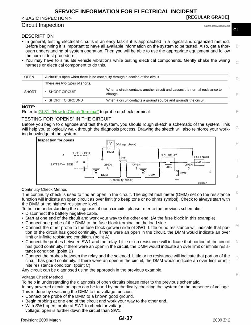
GCircuit Inspection INFOID:0000000004992496
DESCRIPTION • In general, testing electrical circuits is an easy task if it is approached in a logical and organized method.
Before beginning it is important to have all available information on the system to be tested. Also, get a thor-ough understanding of system operation. Then you will be able to use the appropriate equipment and followthe correct test procedure.
• You may have to simulate vehicle vibrations while testing electrical components. Gently shake the wiringharness or electrical component to do this.
NOTE:Refer to GI-31, "How to Check Terminal" to probe or check terminal.
TESTING FOR “OPENS” IN THE CIRCUITBefore you begin to diagnose and test the system, you should rough sketch a schematic of the system. Thiswill help you to logically walk through the diagnosis process. Drawing the sketch will also reinforce your work-ing knowledge of the system.
Continuity Check MethodThe continuity check is used to find an open in the circuit. The digital multimeter (DMM) set on the resistancefunction will indicate an open circuit as over limit (no beep tone or no ohms symbol). Check to always start withthe DMM at the highest resistance level. To help in understanding the diagnosis of open circuits, please refer to the previous schematic.• Disconnect the battery negative cable.• Start at one end of the circuit and work your way to the other end. (At the fuse block in this example)• Connect one probe of the DMM to the fuse block terminal on the load side.• Connect the other probe to the fuse block (power) side of SW1. Little or no resistance will indicate that por-
tion of the circuit has good continuity. If there were an open in the circuit, the DMM would indicate an overlimit or infinite resistance condition. (point A)
• Connect the probes between SW1 and the relay. Little or no resistance will indicate that portion of the circuithas good continuity. If there were an open in the circuit, the DMM would indicate an over limit or infinite resis-tance condition. (point B)
• Connect the probes between the relay and the solenoid. Little or no resistance will indicate that portion of thecircuit has good continuity. If there were an open in the circuit, the DMM would indicate an over limit or infi-nite resistance condition. (point C)
Any circuit can be diagnosed using the approach in the previous example.
Voltage Check MethodTo help in understanding the diagnosis of open circuits please refer to the previous schematic.In any powered circuit, an open can be found by methodically checking the system for the presence of voltage.This is done by switching the DMM to the voltage function.• Connect one probe of the DMM to a known good ground.• Begin probing at one end of the circuit and work your way to the other end.• With SW1 open, probe at SW1 to check for voltage.
voltage: open is further down the circuit than SW1.
OPEN A circuit is open when there is no continuity through a section of the circuit.
SHORT
There are two types of shorts.
• SHORT CIRCUITWhen a circuit contacts another circuit and causes the normal resistance to change.
• SHORT TO GROUND When a circuit contacts a ground source and grounds the circuit.
SGI846-A
GI-37Revision: 2009 March 2009 Z12

[REGULAR GRADE]SERVICE INFORMATION FOR ELECTRICAL INCIDENT
< BASIC INSPECTION >no voltage: open is between fuse block and SW1 (point A).
• Close SW1 and probe at relay.voltage: open is further down the circuit than the relay.no voltage: open is between SW1 and relay (point B).
• Close the relay and probe at the solenoid.voltage: open is further down the circuit than the solenoid.no voltage: open is between relay and solenoid (point C).
Any powered circuit can be diagnosed using the approach in the previous example.
TESTING FOR “SHORTS” IN THE CIRCUITTo simplify the discussion of shorts in the system, please refer to the following schematic.
Resistance Check Method• Disconnect the battery negative cable and remove the blown fuse.• Disconnect all loads (SW1 open, relay disconnected and solenoid disconnected) powered through the fuse.• Connect one probe of the DMM to the load side of the fuse terminal. Connect the other probe to a known
good ground.• With SW1 open, check for continuity.
continuity: short is between fuse terminal and SW1 (point A).no continuity: short is further down the circuit than SW1.
• Close SW1 and disconnect the relay. Put probes at the load side of fuse terminal and a known good ground.Then, check for continuity.continuity: short is between SW1 and the relay (point B).no continuity: short is further down the circuit than the relay.
• Close SW1 and jump the relay contacts with jumper wire. Put probes at the load side of fuse terminal and aknown good ground. Then, check for continuity.continuity: short is between relay and solenoid (point C).no continuity: check solenoid, retrace steps.
Voltage Check Method• Remove the blown fuse and disconnect all loads (i.e. SW1 open, relay disconnected and solenoid discon-
nected) powered through the fuse.• Turn the ignition key to the ON or START position. Verify battery voltage at the battery + side of the fuse ter-
minal (one lead on the battery + terminal side of the fuse block and one lead on a known good ground).• With SW1 open and the DMM leads across both fuse terminals, check for voltage.
voltage: short is between fuse block and SW1 (point A).no voltage: short is further down the circuit than SW1.
• With SW1 closed, relay and solenoid disconnected and the DMM leads across both fuse terminals, check forvoltage.voltage: short is between SW1 and the relay (point B).no voltage: short is further down the circuit than the relay.
• With SW1 closed, relay contacts jumped with fused jumper wire check for voltage.voltage: short is down the circuit of the relay or between the relay and the disconnected solenoid (point C).no voltage: retrace steps and check power to fuse block.
GROUND INSPECTION • Ground connections are very important to the proper operation of electrical and electronic circuits. Ground
connections are often exposed to moisture, dirt and other corrosive elements. The corrosion (rust) canbecome an unwanted resistance. This unwanted resistance can change the way a circuit works.
• Electronically controlled circuits are very sensitive to proper grounding. A loose or corroded ground candrastically affect an electronically controlled circuit. A poor or corroded ground can easily affect the circuit.Even when the ground connection looks clean, there can be a thin film of rust on the surface.
SGI847-A
GI-38Revision: 2009 March 2009 Z12

SERVICE INFORMATION FOR ELECTRICAL INCIDENT[REGULAR GRADE]
C
D
E
F
G
H
I
J
K
L
M
B
I
N
O
P
< BASIC INSPECTION >
G• When inspecting a ground connection follow these rules:- Remove the ground bolt or screw.- Inspect all mating surfaces for tarnish, dirt, rust, etc.- Clean as required to assure good contact.- Reinstall bolt or screw securely.- Inspect for “add-on” accessories which may be interfering with the ground circuit.- If several wires are crimped into one ground eyelet terminal, check for proper crimps. Check all of the wires
are clean, securely fastened and providing a good ground path. If multiple wires are cased in one eyeletcheck no ground wires have excess wire insulation.
• For detailed ground distribution information, refer to “Ground Distribution” in PG section.
VOLTAGE DROP TESTS • Voltage drop tests are often used to find components or circuits which have excessive resistance. A voltage
drop in a circuit is caused by a resistance when the circuit is in operation.• Check the wire in the illustration. When measuring resistance with DMM, contact by a single strand of wire
will give reading of 0 ohms. This would indicate a good circuit. When the circuit operates, this single strandof wire is not able to carry the current. The single strand will have a high resistance to the current. This willbe picked up as a slight voltage drop.
• Unwanted resistance can be caused by many situations as follows:- Undersized wiring (single strand example)- Corrosion on switch contacts- Loose wire connections or splices.• If repairs are needed always use wire that is of the same or larger gauge.
Measuring Voltage Drop — Accumulated Method• Connect the DMM across the connector or part of the circuit you want to check. The positive lead of the
DMM should be closer to power and the negative lead closer to ground.• Operate the circuit.• The DMM will indicate how many volts are being used to “push” current through that part of the circuit.
SGI853
GI-39Revision: 2009 March 2009 Z12
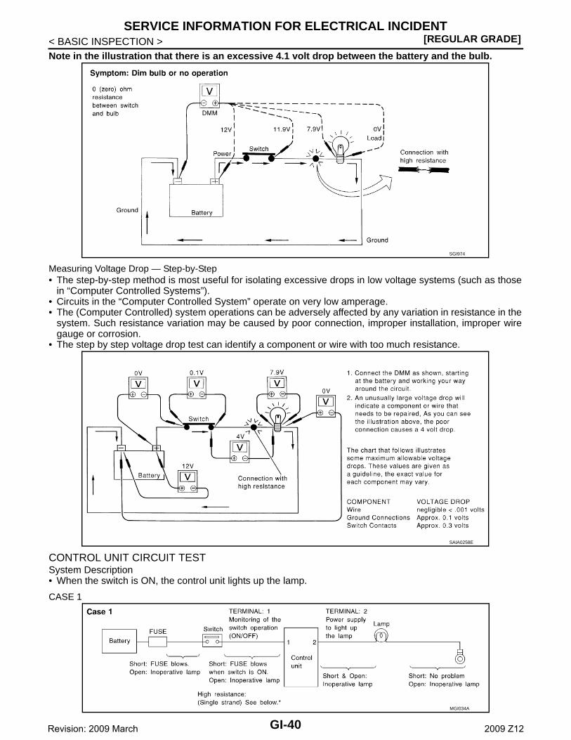
[REGULAR GRADE]SERVICE INFORMATION FOR ELECTRICAL INCIDENT
< BASIC INSPECTION >Note in the illustration that there is an excessive 4.1 volt drop between the battery and the bulb.
Measuring Voltage Drop — Step-by-Step• The step-by-step method is most useful for isolating excessive drops in low voltage systems (such as those
in “Computer Controlled Systems”).• Circuits in the “Computer Controlled System” operate on very low amperage.• The (Computer Controlled) system operations can be adversely affected by any variation in resistance in the
system. Such resistance variation may be caused by poor connection, improper installation, improper wiregauge or corrosion.
• The step by step voltage drop test can identify a component or wire with too much resistance.
CONTROL UNIT CIRCUIT TEST System Description• When the switch is ON, the control unit lights up the lamp.
CASE 1
SGI974
SAIA0258E
MGI034A
GI-40Revision: 2009 March 2009 Z12

SERVICE INFORMATION FOR ELECTRICAL INCIDENT[REGULAR GRADE]
C
D
E
F
G
H
I
J
K
L
M
B
I
N
O
P
< BASIC INSPECTION >
GINPUT-OUTPUT VOLTAGE CHART
• The voltage value is based on the body ground.
• *: If high resistance exists in the switch side circuit (caused by a single strand), terminal 1 does not detect battery voltage. Control unitdoes not detect the switch is ON even if the switch does not turn ON. Therefore, the control unit does not supply power to light up thelamp.
CASE 2
INPUT-OUTPUT VOLTAGE CHART
• The voltage value is based on the body ground.
• *: If high resistance exists in the switch side circuit (caused by a single strand), terminal 2 does not detect approx. 0 V. Control unitdoes not detect the switch is ON even if the switch does not turn ON. Therefore, the control unit does not control ground to light up thelamp.
Terminal No. Description
Condition Value (Approx.)In case of high resistance such as single strand (V) *+ − Signal name
Input/Output
1Body ground
Switch InputSwitch ON Battery voltage
Lower than battery voltage Approx. 8 (Ex-ample)
Switch OFF 0 V Approx. 0
2Body ground
Lamp OutputSwitch ON Battery voltage Approx. 0 (Inoperative lamp)
Switch OFF 0 V Approx. 0
Terminal No. Description
Condition Value (Approx.)In case of high resistance such as single strand (V) *+ − Signal name
Input/Output
1Body ground
Lamp OutputSwitch ON 0 V Battery voltage (Inoperative lamp)
Switch OFF Battery voltage Battery voltage
2Body ground
Switch InputSwitch ON 0 V Higher than 0 Approx. 4 (Example)
Switch OFF 5 V Approx. 5
MGI035A
GI-41Revision: 2009 March 2009 Z12

[REGULAR GRADE]CONSULT-III/GST CHECKING SYSTEM
< BASIC INSPECTION >
CONSULT-III/GST CHECKING SYSTEM
Description INFOID:0000000004992497
• When CONSULT-III/GST is connected with a data link connector(A) equipped on the vehicle side, it will communicate with the con-trol unit equipped in the vehicle and then enable various kinds ofdiagnostic tests.
• Refer to “CONSULT-III Software Operation Manual” for more infor-mation.
CONSULT-III Function and System Application*1 INFOID:0000000004992498
x: Applicable
*1: If GST application is equipped, functions in accordance with SAE J1979 and ISO 15031-5 can be used.
CONSULT-III/GST Data Link Connector (DLC) Circuit INFOID:0000000004992499
INSPECTION PROCEDUREIf the CONSULT-III/GST cannot diagnose the system properly, check the following items.
1 : Instrument driver lower panel
JPAIA0582ZZ
Diagnostic test mode Function
EN
GIN
E
TR
AN
SM
ISS
ION
AIR
BA
G
ME
TE
R/M
&A
BC
M
AB
S
IPD
M E
/R
AIR
PR
ES
SU
RE
MO
NIT
OR
EP
S
SO
NA
R
Work supportThis mode enables a technician to adjust some devices faster and more accurately.
x x - - x x - x - x
Self Diagnostic Results Retrieve DTC from ECU and display diagnostic items. x x x x x x x x x x
Data monitorMonitor the input/output signal of the control unit in real time.
x x - x x x x x x x
CAN diagnosisThis mode displays a network diagnosis result about CAN by a diagram.
x x x x x x x - x -
CAN diagnosis support monitor
It monitors the status of CAN communication. x x - x x x x - x -
Active testSend the drive signal from CONSULT-III to the actuator. The operation check can be performed.
x - - - x x x x - x
DTC & SRT confirmationThe status of system monitoring tests and the self-diagno-sis status/result can be confirmed.
x - - - - - - - - -
ECU IdentificationDisplay the ECU identification number (part number etc.) of the selected system.
x x x - x x - - x x
Function testThis mode can show results of self-diagnosis of ECU with either “OK” or “NG”. For engines, more practical tests re-garding sensors/switches and/or actuators are available.
x x x - - x - - - -
Configuration Function to READ/WRITE vehicle configuration. - - - - x - - - - -
Special FunctionOther results or histories, etc. that are recorded in ECU are displayed.
- x x x - - - - - -
GI-42Revision: 2009 March 2009 Z12

CONSULT-III/GST CHECKING SYSTEM[REGULAR GRADE]
C
D
E
F
G
H
I
J
K
L
M
B
I
N
O
P
< BASIC INSPECTION >
G
NOTE:The DDL1 and DDL2 circuits from DLC pins 12, 13, 14 and 15 may be connected to more than one system. Ashort in a DDL circuit connected to a control unit in one system may affect CONSULT-III access to other sys-tems.If the GST cannot operate properly, check the circuit based on the information of SAE J1962 and ISO 15031-3.
Symptom Check item
CONSULT-III/GST cannot ac-cess any system.
• CONSULT-III/GST DLC power supply circuit (Terminal 8 and 16) and ground circuit (Terminal 4 and 5)
CONSULT-III cannot access in-dividual system. (Other sys-tems can be accessed.)
• Power supply and ground circuit for the control unit of the system (For detailed circuit, refer to wiring diagram for each system.)
• Open or short circuit between the system and CONSULT-III DLC (For detailed circuit, refer to wiring diagram for each system.)
• Open or short circuit CAN communication line. Refer to LAN-14, "Trouble Diagnosis Flow Chart".
GI-43Revision: 2009 March 2009 Z12

[REGULAR GRADE]CONSULT-III/GST CHECKING SYSTEM
< BASIC INSPECTION >
Wiring Diagram - CONSULT-III/GST CHECKING SYSTEM - INFOID:0000000004992500
JCAWM0173GB
GI-44Revision: 2009 March 2009 Z12

CONSULT-III/GST CHECKING SYSTEM[REGULAR GRADE]
C
D
E
F
G
H
I
J
K
L
M
B
I
N
O
P
< BASIC INSPECTION >
G
JCAWM0174GB
GI-45Revision: 2009 March 2009 Z12

[REGULAR GRADE]CONSULT-III/GST CHECKING SYSTEM
< BASIC INSPECTION >
JCAWM0175GB
GI-46Revision: 2009 March 2009 Z12

INSPECTION AND ADJUSTMENT[REGULAR GRADE]
C
D
E
F
G
H
I
J
K
L
M
B
I
N
O
P
< BASIC INSPECTION >
GINSPECTION AND ADJUSTMENTADDITIONAL SERVICE WHEN REMOVING BATTERY NEGATIVE TERMINAL
ADDITIONAL SERVICE WHEN REMOVING BATTERY NEGATIVE TERMINAL : Re-quired Procedure After Battery Disconnection INFOID:0000000004992501
*: Not equipped.
SYSTEM ITEM REFERENCE
Automatic temperature control
Temperature setting trimmer HAC-11, "Temperature Setting Trimmer"
Foot position setting trimmer* —
Inlet port memory function HAC-12, "Inlet Port Memory Function"
Inlet port memory function (FRE)* —
Inlet port memory function (REC)* —
Gas sensor sensitivity adjustment function* —
Auto intake switch interlocking movement change* —
Clean switch interlocking movement change* —
Automatic drive positioner* Automatic drive positioner system —
Power window control Power window control systemPWC-4, "ADDITIONAL SERVICE WHEN RE-MOVING BATTERY NEGATIVE TERMINAL :
Description"
Sunroof system* Sunroof system —
Sunshade system* Sunshade system —
Rear view monitor*Rear view monitor possible route line center position adjustment
—
Around view monitor* Predicted conurse line center position adjustment —
Automatic back door system* Automatic back door system —
Engine oil level read* Engine oil level read —
GI-47Revision: 2009 March 2009 Z12

[Krom]DIMENSIONS AND WEIGHTS
< VEHICLE INFORMATION >
VEHICLE INFORMATIONDIMENSIONS AND WEIGHTS
Dimensions and Weights INFOID:0000000005155898
*1: With front license plate bracket
*2: Without front license plate bracket
Vehicle body Krom
Overall length in (mm)157.8 (4,010) *1
157.5 (4,000) *2
Overall width in (mm) 66.7 (1,695)
Overall height in (mm) 65.0 (1,650)
Front tread in (mm) 58.1 (1,475)
Rear tread in (mm) 58.3 (1,480)
Wheel base in (mm) 99.6 (2,530)
Gross vehicle weight rating (GVWR) lb (kg)
See the F.M.V.S.S. or C.M.V.S.S. certifi-cation label on the driver′s side lock pill-er.
Gross axle weight rating (GAWR) lb (kg)
Front lb (kg)
Rear lb (kg)
GI-48Revision: 2009 March 2009 Z12

LIFTING POINT[Krom]
C
D
E
F
G
H
I
J
K
L
M
B
I
N
O
P
< PRECAUTION >
GPRECAUTIONLIFTING POINT
Lifting Point INFOID:0000000005155899
Lift-up points are located behind the side sill extensions.When using an on-board lift, use some attachments as shown in thefigure.Using unsuitable Lift may damage the side sill extensions.
JKAIA0001GB
GI-49Revision: 2009 March 2009 Z12

[Krom]TOW TRUCK TOWING
< PRECAUTION >
TOW TRUCK TOWING
Tow Truck Towing INFOID:0000000005155900
CAUTION:Place the vehicle only on a flat bed type truck. Other towingmethods may damage the front bumper or rear bumper.Place the vehicle on a flat bed truck as shown in the figure. Towingthe vehicle with a sling type tow truck may damage the front bumperor rear bumper.
CAUTION:Since the approach angle and the departure angle of the vehicleare smaller, front bumper fascia and rear bumper fascia mayinterfere in the road surface when entering and exiting from aparking lot or the steep slope. Therefore, be sure to reduce thespeed sufficiently and drive carefully.
Vehicle Recovery (Freeing a Stuck Vehicle) INFOID:0000000005155901
For complete information regarding vehicle recovery, see “Vehicle recovery (Freeing a stuck vehicle)” in the “Incase of emergency” section of the Owner's Manual. Use the recovery hook by installing it in the front of thevehicle. (The rear has no towing points.)
REMOVING THE TOE HOOK COVER1. To remove the cover, insert a tapered tool (ex. flat-blade screw-
driver) into the cover groove in parallel with the ground.2. While pushing the cover downward (direction 1), pull (direction
2) it to disengage.CAUTION:Use a cloth for the tool during the removal to prevent damage tothe vehicle.
JKAIA0004ZZ
JKAIA0029ZZ
JKAIA0005GB
GI-50Revision: 2009 March 2009 Z12

TOW TRUCK TOWING[Krom]
C
D
E
F
G
H
I
J
K
L
M
B
I
N
O
P
< PRECAUTION >
GINSTALLING THE TOE HOOK COVER1. Fit the toe hook cover at an angle in the position shown by the
arrow (1) in the figure.
2. Push the toe hook cover downward (2) by sliding the diagonally-shaded area of the cover along the inner side of the housing.
3. Push the toe hook cover in by pushing the top of the coverdownward.
JKAIA0002GB
JKAIA0003GB
JKAIA0006GB
GI-51Revision: 2009 March 2009 Z12