general electric - store.gegridsolutions.com · _tatotrol jr dc drive , , ,,gek'36378 table 1...
TRANSCRIPT

GEK-36378D
INSTRUCTIONS
J
%
STATOTROL*JR DC DRIVE/
(Up thru 2 Horsepower)
3SJRB AND. 3SJRC SERIES
*Registeredtrademark of General Electric Company, USA
--, , ,
,LL
W
//,,
/
GENERAL_ ELECTRIC ';

STATOTROL JR DC DRIVE 0EK-36378. III I [111 I ITIl 1 I [ Ill 11 TH
!
TABLE OF CONTENTS
PAGE
INTRODUCTION AND DESCRIPTION .................................................. 3
RECEIVING AND STORAGE .......................................................... 3
INS TALLATION .................................................................... 3
Controller Installation ......................................................... 3Motor Installation .............................................................. 3
ELECTRICAL CONNECTIONS ....................................................... 3
Proper Line Voltage Connections ................................................ 3Grounding .................................................................... 3Power Wiring .................................................................. 6Remote Control Station Wiring .......... : ....................................... ' 6
PREPOWER CHECES AND ADJUSTMENTS ............................................ 7
Current Limit Setting .......................................................... 750 Hz Adjustment ............................................................. 8Motor Check ................................................................ 8
Wiring Check ................................................................ 8Grounding ................................................................. 9Power Line Connections ....................................................... 9
INITIAL OPERATION AND ADJUSTMENT ............................................. 9
Minimum Speed Adjustment .................................................. 9Maximum Speed Adjustment .................................................. 9
OPERATOR CONTROI_, NORMAL OPERATION ..................................... 9
MAINTENANCE................................................................... 9
Controller .................................................................. 9Motor ......................................................................... 9Gearbox ................................................ .................... 10
TROUBLESHOOTING AND REPAIR .................................................. 10
Symptoms and Their Probable Causes ........................................... 10Repair ........................................... _ .......................... , 11
RENEWAL PARTS.................................................................. 11
Theseinstructionsdo notpurporttocoveralldetailsor variationsin equipmentnor toprovidefor everypossiblecontingencytobemetinconnectionwrYhinstallation,operationor maintenance.Shouldfurtherinformationbedesiredar shouldparticular,problemsarisewhicharenotcoveredsufficientlyfor thepurchaser'spurposes,themattershouldbereferredtoGeneralElectricCompany.
2

$IAI'OTROL JR .DCDRIVE ...... : GEK236378
STATOTROL JR DC DRIVE
INTRODUCTION AND DESCRIPTION INSTALLATION
This manual contains general information on General CONTROLLER INSTALLATIONElectric Statotrol JR DC drives. Additional infor-mation and diagrams may be supplied with the equip- The Statotrol JR Control should be wall mounted in ament when necessary. The Statotrol JR drive is a location which will allow free flow of cooling air overcompact, reliable, full wave DC motor control speci- the fins on the heat sink. Maximum ambient temper-ally designed for applications requiring only the basic ature around the controller must not exceed 40°Cstart, stop, and speed control functions. The motor (104°F)o Figures 2 and 3 give mounting dimensionsis either a shunt wound or permanent magnet field DC and outline dimensions. It is recommended that twomotor designed for use with a full wave phase con- or more inches of clearance be provided all aroundtrolled SCR power supply. Standard features o£the the controller to assure adequate air flow for cooling.Statotrol JR drive include speed control, protectivecurrent limit, line fuse, stop-start switch, and max-imum speed and minimum speed adjustments. MOTOR INSTALLATION
The motor must be firmly mounted and properly: "_ aligned to prevent vibration. Excessive vibration
causes rapid wear and audible noise. Heat dissipatedby the motor will raise the ambient temperaturearound the motor if the motor is installed in an en-closed space. Since a lower ambient temperaturewill extend the motor life, it is always desirable tomount the motor in a well ventilated location. Themotor should never be used where the ambient temper-
' ature exceeds 40°C (104°F) unless an oversized motor:" has been specially selected. An instruction book pro-
vided with i 1/2 and 2 HP motors gives additional in-;_ formation for these motors.
_'i If the motor is accessable while it is run-ning, a protective guard should be installedaround all exposed rotating parts°
J ELECTRICALCONNECTIONS
:_' PROPER LINE VOLTAGE CONNECTION
: ';; ': _:_ The controller operates on 50/60 cycles AC. Inputvoltage rating is either 115 volts or 230 volts, not
Figure 1. Enclosed 3SJRB (left) and chassis mount both. Cheek the nameplate to det_-mine proper_put3SJRC (right) models of the Statotrol JR motor control ol v-_--tage. A transformer is required where supply volt-
age deviates more than 10% from the controller rating.
RECEIVING AND STORAGE A calibration resistor, 140R must be removed fromthe main component board if 50 Hz power is to be
As soon as the equipment is received, it should be used. Refer to Figure 5.unpacked and examined for damage sustained in trans-it. If damage is evident, a damage claim should befiled immediately with the transportation company, GROUNDING I la
and the local General Electric COoSales Office should I WARNING Ibe promptly notified. I l
If the equipment is not to be used as soon as it is un- Personnel safety considerations and thepacked, it should be stored in a clean, dry place and National Electric Code require that elec-protected against accidental d_mage. Avoid storage trical apparatus enclosures be solidly con-in a location where construction work is in progress, nected to building ground.
3

S;ATOmOt,,RDCDmVi , _ _ o;K-3_!7.8
r 3"
m
0
,4.,, Q;'"/._ .t'bL_''5 f"o,,_/i'
W_LE
,, [ /0_'// /
ENCLOSED MODEL WITH CONTROL STATION
i
3_,,I i
_ ,El dll d --.
'-- '1 illl,I I/I [] I I I orv.__oo.,-._.
t_A_o,_r _IIC&M **,_ICIE VIEt_V k'£ y/_'ozci
OPEN MODEL FOR USE WITH REMOTE CONTROL STATION
Figure 2. Outline and Mounting Dimensions for Statotrol JR Controllers(i Horsepower and Less)

"'STATOTROL JR DC DRIVE ,GEK-36378
I ' ,I _;y_o,_I IDD_DDI .-_-'L/ ',.-?, fl _E_-_,I i_BEII"¥-3/ r'""_l_' ! -_/_?n°_'ll\
I_-7 ;4-1TM I luH_ol, _,.o....
ENCLOSED MODEL WITH CONTROL STATION
---- _ 3_ #
f "T_,_o_,_
F_ (pry 3 _oo_r_
7_i_OV/Oi_'O bViT'/-i----T
I
OPEN MODEL FOR USE WITH REMOTE CONTROL STATION
Figure 3, Outlineand Mounting Dimensions for StatotrolJR Controllers(1 1/2 and 2 Horsepower)
5

STATOTROL JR DC DRIVE _- _ GEK-36378
The necessary wire gauge of the grouna wire is de- WA[ 'btermined by the rating of the branch circuit breaker.Connect a suitably grounded lead to the ground con-nection terminal provided in the wire-well below 1TB Since the Controiler stop button ,and fusein the controller enclosure. Do not rely or depend on do not remove voltage from the controllermounting bolts for a ground connection, or the motor field, a branch circuit breaker
or a fused disconnect switch must be used
WA_ to disconnect the Controller whenever servicework is to be performed on the drive°
Proper Motor Grounding is Essential forPersonnelSafet_. 65 I0 2 35 34 2TB is used
Do not depend upon motor mounting bolts to ground ___ 3SJRC seriesthe motor frame. The ground connection provided with which ain the motor depends upon thetype, size, and en-closure of the motor. Each Statotrol motor has one START remote con-
STOP trol stationof the following provisions for connecting a ground SPEED SWITCH is requiredlead.
1. A 4 inch green wire inside the wire well.
end shield. I ]Al A2 F F2 LI L2
3. A brass screw which serves as a ground ter- ,GROUND IIrninal and also mounts the conduit box found on the 'CONTI_OLLERside of TEFC motors. ENCLOSURE
4. A drilled hole in the motor end shield (inside Al A2 FI F2 '/
the wire well near the electrical terminals) suitable - _ l I 50/60 I-Iz AC line voltage
for a self tapping screw. (see control nameplate forvoltage). C_tomer must
POWER WIRING provide branch circuitbreaker or disconnect for
A six point terminal strip, 1 TB, is provided for removing power from con-connection to the AC power liner and the motor leads, troller when maintenanceFigure 4 shows the wiring diagram for the power GROUND is required. If one ACconnections. When the motor is connected as shown MOTOR--_ power lead is grounded,
in Figure 4, the motor will rotate CCW as viewed FRAME ] _ that lead must be connectedfrom the end which has no shaft. Reverse leads A1 ___ to terminal L2. If lineand A2 for Clockwise rotation. All power wires voltage transformer isshould be kept away from the component board° used, the line switch for
dis-connecting the control-:_-;_-'_:-_-:C-A:_uTtON_ ler should be on the load
side of the transformer.A connection error in the power wiringcan damage the control. Recheck the Figure 4. Statotrol JR Controller Connection Diagramconnections before power is applied.
If there is any doubt about motor lead identification, The branch circuit breaker must be large enough tothe problem can be resolved with a simple resistance eliminate nuisance tripping and small enough to pro-check. The motor armature resistance will be about tect the branch circuit and motor connection con-0.3 to 15 ohms, while field resistance will be about 75 ductors. Refer to the National Electric Code (1971,to 1000 ohms. There must be no continuity between section 310-20) and Table I below for minimum cir-armature and field. Permanent magnet DC motors cult breaker and wii-e sizes. Wherever local codeshave armature leads, but no field leads. 1 1/2 and are more restrictive, the local codes take precendenc_2 HP motors may have leads labled C1 and C2. These over the National Electric Code. Special require-leads should be well insulated and left unconnected, ments exist for installations in hazardous locations
and other special situations°
1 1/2 and 2 HP motors may have four field leads, When one side of the AC power ltne.i_ grounded, thatmar_ked FI_ F2, F3 and F4. In this case_ connect side must be connected to terminal L2 on 1TB. Whenmotor leads F2 and F3 together and connect motor a line power transformer is used, the line switch usedleads F1 and F4 to controller terminals F1 and F2. to disconnect the controller should be on the load side
of the' transformer.
6

_TATOTROL JR DC DRIVE , , ,,GEK'36378
TABLE 1
RATED VOLTAGE AND HORSEPOWER WIRE AND CIRCUIT BREAKER SIZE
up to 1/2 HP 115 volt 75°C $14 AWG copper wire
up to 1 HP 230volt and 15amp circuit breaker
3/4 HP 115 volt 75°C S12 AWG copper wire
I 1/2 and 2 HP 230 volt and 20 amp circuit breaker
REMOTE CONTROL STATION WIRING CURRENT LIMIT SETTING
The currentlimitcircuitisfactoryadjustedfor lowIfthecontrollerisone ofthe3SJRC series,itis impedance motors. Ifa medium or highimpedanceintendedforuse witha remote controlstation.The
motor istobe used, thecurrentlimitmust be ad-remote controlstationshouldbe connectedtoterminaljusted at the time of installation. To set the current
strip 2TB as shown in Figure 4. If the input power limit, first refer to Table 2 and locate the motorto the controller is 115 volts AC, the three leads to which is to be used. After finding the relative ira-the speed control potentiometer are Class II control pedance of the motor to be used, refer to Figure 5circuits as defined in Article 725 of the National for instructions on how to position the current limitElectric Code (1971). If the input power is 230 volts, setting jumper.the speed control potentiometer conductors should
be installed in accordance with the Class I control {' {and signal circuit requirements of the code. Wher-ever local codes are more restrictive, the local codes
take precedence. The leads to the start-stop switch Jumper 6 to 62 forshould always be installed ha accordance with the High Impedance Motorspower wiring requirements and Table I. Do not run 62 to 63 for Mediumthe switch leads in the same harness or conduit withthe speed control potentiometer leads. 6Z O Impedance Motors, or
6 to 63 for Low Impe-
To avoid electrical noise pickup, it is necessary to 65 o dance Motors (Seekeep the speed potentiometer wires separate from Table II)all other wires. Do not nm these wires through con- $ o {duffs with power conductors or relay coil wiring. Donot allow any wiring to contact building ground unlessa line power isolation transformer is used. In nocase should more than one circuit point be grounded. Cut 140R out of
circuit before
If speed potentiometer leads are run in shielded cable, applying 50 Hzthe cable shield should be connected to circuit 2 at powerthe controller only. The cable shield must beinsulated and must not come into contact with plant F ·
groundat anypoint. { ITB JPREPOWERCHECKSAND ADJUSTMENTS
[ ARNINGiW Figure 5. Current Limit Setting and 50 Hz Adjustment,
This section contains cautions and warningswhich must be observed during installationof the control. Failure to observe thesecautions and warnings may lead to safetyhazards or equipment damage. Read thissection carefully and make all necessarychecks and adjustments before power isapplied to the control.

$T.A_TO__J,.._0LJ____D1._ DR_{VE _ GEK-36378
TABLE 2
CURRENT LIMIT SETTINGS FOR STATOTROLMOTORS WITH "3SFM .... "CATALOG NUMBER ON NAMEPLATE
1140 RPM Drip Proof and totally enclosed High Impedance Motors1725 RPM Drip Proof* (Except 1 1/2 & 2 (jumper 6 to 62)HP. See below)
\
1725 RPM totally enclosed non ventilated Medium Impedance& totally enclosed fan cooled 2500 RPM Motors (jumper 62 to 63)Drip Proof
2500 RPM totally enclosed non ventilated &totally enclosed fan cooled Low Impedance Motors
3450 RPM motors Drip Proof & totally enclosed (jumper 6 to 63)
Any motor which does not have 3SFM .... Refer to Factory for Instructions /catalog number, on nameplate
C_{UTION: i 1/2 &2 HP 1750 I_PM Drip Proof MOtors require jumper from 6 to 63.
50 CYCLE POWER ADJUSTMENT WIRiNG CHECK
The Statotrol JR controller is factory adjusted for Any connection error in the power wiring can damageuse with 60 Hz AC power. If 50 Hz power is to he the control as soon as power is applied. Any shortused, resistor 140R must be cut out of the circuit to building ground in the wiring can cause damage asbeiare 50 Hz power is_applied. See Figure 5 for the soon as power is applied, unless the controller islocation of 140R. connected to a line power isolation transformer. If
the controller is connected to any instruments orMOTOR CHECKS equipment which may be grounded, a line isolation
transformer must be used. In no case should theIf the motor is accessable while 'running, a pro- circuit be grounded at more than one point. It istective guard should be installed around all rotating advisable to recheck all wiring before power isj applied.parts° When installing 1 1/2 or 2 HP motors, read Make certain that all screw terminals are tight. Ifthe "Inspection Before Starting" section of the motor an ohmmeter is available, the simple resistanceinstruction book. checks shown in Table 3 should be performed to verify
that the wiring is correct.
TABLE 3
PREPOWER WIRING CHECKS
TERMINALS APPROPRIATE RESISTANCE
L1 to L2 150 ohms or more(with branch circuit breaker open)
F1to F2 75to 1000ohms
A1 to A2 0. 3 to 15 ohms
F1 to A1 or F2 to A2 500, 000 ohms or more
Control Circuit to Ground 500, 000 ohms or more(See exceptions in preceding paragraph)

STATOTROL JR,DC DRIVE ,, GEK-36378
GROUNDING Adjusting the minimum speed will change the maximumspeed setting, so the minimum speed potentiometer
Safety considerations and the National Electric code should be adjusted before the maximum speed potenti-require the motor frame and the controller enclosure ometer is adjusted.to be connected solidly to building ground. Do not relyon mounting bolts for grounding. Refer to the "Elec- MAXIMUM SPEED ADJUSTMENTtrical Connections section of this instruction book
for ground lead connections. The maximum speed adjustment is factory set to aspeed slightly higher than rated motor speed. To
POWER LINE CONNECTIONS change the maximum speed, first turn the speed con-trol knob to its highest speed setting. Then adjust the
If one AC power lead is grounded, that lead must be maximum speed potentiometer until the motor runs atconnected to terminal L2 since the controller fuse is the highest speed needed for the particular application.connected to terminal L1.
The switch in the controller does not remove power The Statotrol JR drive may not meet its performancefrom the controller or the motor field, so a branch specifications when the motor is run above its ratedcircuit breaker or a fused disconnect must be used speed. It is, therefore, recommended that the maxi-
mum speed be set for rated motor speed or less.to disconnect the AC line whenever it is necessaryto perform work on the motor or the controller. Ifa line power transformer is used, the circuit breakeror disconnect should be on the load side of the trans- OPERATOR CONTROLS, NORMALformer. OPERATIONINITIAL OPERATION AND ADJUSTMENT The operator controls have been made as simple and
foolproof as possible. However, in certain applica-When the control has been mounted and connected, tions, it may be necessary to warn the machineand the prepower checks and adjustments are corn- operator against operation sequences which may dam-plete, set the controller switch to "stop", apply age the machinery or process driven by the Statotrolpower to the control, turn the speed control knob to motor. The following instructions apply only whenzero, and operate the controller switch. Slowly turn the customer's load requires no special operatingthe speed control knob until the motor starts to turn. sequences.Check the direction of motor rotation to be sure it is The speed control knob may be at any desired settingcorrect. If the motor turns the wrong way, discon- when the drive is started. The motor will accelerate
nect power from the control and reverse the motor smoothly to the speed set by the speed control knob.armature leads. When installing 1 1/2 or 2 tip mo- Motqr current is automatically limited to a safe value.tors, refer to the "Inspection After Starting" section No warmup is required, and motor response is frame-of the motor instruction book. diateo The speed control knob may be turned to any
desired setting at any time, and the motor will respondsmoothly. Turning the speed control knob clockwise
The control is now ready for normal operation. Some will increase the motor speed. The controller switchapplications may require special settings for maxi- may be moved to "stop" at any time, regardless ofmum and minimum speed. Potentiometers for ad- the speed setting.justing these functions are at the upper end of themain component board inside the controller. Removethe Statotrol JR controller cover and use a smallscrewdriver to adjust the potentiometers as described M Al NTENAN CEin the following instructions.
iWA_ CONTROLLERThe controllerenclosureshouldbe periodicallyin-
AC power linevoltageisexposedwhen the spectedtopreventan accumulationofmaterialswhichprotectivecover is removed. Use extreme might blockthe flowofcoolingairthroughtheheatcare to avoidtouchingany exposedconduc- sinkfins. The 1 1/9.HP and 9 HP unitsalso_havetorsinsidethe controller°Internalad- airventholesinthecover which must be keptclear.
justmentsshouldbe made onlyby qualifiedelectricians. MOTOR
MINIMUMSPEED ADJUSTMENT Bearings
The minimum speed adjustment is factory set so In general, opening Statotrol motors for bearingthat the motor will start to run when the speed con- maintenance will create more problems than it willtrol knob is turned just slightly off zero. To change prevent. However, if for some reason it is felt thatthis setting, first turn the speed control knob to zero bearing maintenance is necessary, the bearings shouldand then rotate the minimum speed potentiometer be relubricated or replaced after 5 years of normaluntil the motor runs at the desired minimum speed, service or 2 years of severe duty.

STATOTROL JR DC DRIVE ,r _r........ lr_EK'i36378
Brushes Symptoms and Their Probable Cause_s
Brushes should be inspected after every 1000 hours Motor will not Runof operation. Replacement brushes should be in-stalled before old brushes wear down to 3/8 of an First check the branch circuit breaker to be certaininch in length. Replacement brushes must be pre- it is closed. Then open the branch circuit breakershaped to approximately conform to the curved corn- and check the fuse in the controller. If necessary,mutator surface, The motor should be run near replace it with a fuse of the same type and amperagerated speed for about 12 hours with no load to seat rating as the original fuse. Next move controllerthe new brushes before the motor is returned to switch to "stop", close the circuit breaker, and con-normal duty. Failure to seat the new brushes may neet an AC voltmeter across terminals L1 and L2 oncause commutator damage and rapid wear. Replace- 1TB and verify that the voltage is within 10% of thement brushes must be of the type recommended by line voltage rating on the nameplate of the control.the motor manufacturer. Next connect a DC voltmeter from F1 to F2 on 1T:B
and verify that the voltage is within + 10% of the fieldMounting voltage stated onthe nameplate. If ['hefield voltage
is 1/2 of the rated value, one of the diodes in theThe motor should be inspected periodically to assure field power supply has probably failed. These diodesthat the mounting bolts are tight. Loose mounting are marked 16D, 17D, lSD, and 19D, and are mountedbolts can cause vibration, rapid wear, and misalign- near 1 TB on the controller main component board.mont. Proper alignment of motor couplings must be If the field voltage is zero, 2 or more diodes maymaintained, have failed, or the fuse may be open. If the field
voltage is correct, move the controller switch toVentilation start, turn the speed control knob to full speed, and
read thc DC voltage across terminals A1 and A2 onDo not allow an accumulation of materials to block 1TB. If this voltage is about 10 or 20 volts, the motorcooling air from flowing through self ventilated motors is stalled due to an overload or there is an open inor over totally enclosed motors, the motor leads, windings, or brushes. If this volt-
age is zero, turn the minimum speed adjustmentGearbox slowly from one extreme to the other. If the motor
now starts, the problem is probably in the controlPeriodic oil changes and bearing lubrication are station and its plug-in contacts should be checked andnecessary to prolong the life of most gearboxes_ Re- then the control station should be replaced. If thefor to the instructions provided with the unit for re- motor does not start, the main component boardcommended maintenance schedule and lubricants, along with the power semiconductor package, should
TROUBLESHOOTING AND REPAIR be replaced.
WARNING i Motor Runs at High Speed and Cannot be Controlled! The most probable cause for this symptom is a short
Line voltage is exposed when the controller circuit in the reference circmt. Turn off the AC powercover is removed. Use extreme care to and inspect the wires to the speed control potentiometer.avoid touching exposed conductors. Always If no problem _s observed, turn on the AC power anddisconnect the AC power before doing any-, turn the maximum and minimum speed potentiometersthing other than adjusting potentiometers, full CCW. If the motor comes down to a very low speed,
the speed control potentiometer may be shorted. If theThe "stop" switch does not remove powerfrom the controller or the motor field, motor still runs at a very high speed the main compone:
board should be replaced.
If a newly installed drive will not run, it is mostlikely that a terminal is loose or a problem exists Motor Operates Normally at no Load, But will notwith a connection, line voltage, or an adjustment. Deliver Adequate Torque to Drive a Load
Line voltage must be within ±10% of the nameplate If the motor has operated properly in the past andrating of the controller, and the adjustments must suddenly develops this symptom, the main componentbe set as described in the "Prepower Checks and board and/or the power semiconductor package shouldAdjustments" section of this book. If the drive be replaced.
operates normally for a while and then malfunctions, If this problem is evident immediately upon installa-the problem may be line voltage, motor overload, tion, refer to the section of this book titled "Pre-motor failure, a loose terminal, an open fuse, or a power Checks and Adjustments" and check the currentcomponentfailure, limit setting of the control. If it is wrong, disconnect
In the following discussions, each step of trouble- the AC power and correct the setting. If it was setper the table, then disconnect the AC power, connectshooting is based on the assumption that all pre- AC & DC ammeters in series with the motor armature,ceding steps have been completed and no problems and run the motor with the load connected. If the ob-
have been found, served DC current is more than the nameplate rating
10

_/ I /411 I_/ I R _'vll I' J I_ ILJ _" I'/R I V Ir' _;:'- , II I ll_ I[I I_ ' '_ _ "'1 / 0
on the motor, either the motor has failed or the motor FUSE TABLEis overloaded. If the observed DC current is less
than the nameplate rating of the motor, and if the AC Oversize fusecurrent is less than 1.5 times the armatUre currentDrive horsepower Standard fuse- for intermittent
nameplated rating of the motor, disconnect the AC and line voltage Buss ABC or duty - Busspower and reset the current limit adjustment to the rating Littlefuse 314 ABC or Little-setting appropriate to the next higher impedance group fuse 314of motors in Table 2 and once again run the motor un-der load. If the DC armatUre current exceeds thenameplate rating on the motor, the motor is overloaded. 1/6 HP l15V 4 amp 6 ampIf the DC armature current does not exceed rated cur- 1/4 HP 115V 5 amp 7 amprent, but the AC current is greater than 1.5 times 1/3 HP 115V 7 amp 10 amprated current, the main component board and/or the 1/2 HP l15V 10 amp 15 amppower semiconductor package should be replaced. 3/4 HP 230V 7 amp 10 amp
1 HP 230V 10amp 15ampMotor Runs Very Fast For Speed Setting, But Very i 1/2 HP 230V 15 amp 20 amp*Little Torque is Produced: 2 HP 230V 15 amp 20 amp*
Check the AC line voltage from L1 to L2 on 1TB. *The 20 amp fuse is not listed by UnderwritersVerify that this voltage is within + 10% of the value Laboratories.stated on the nameplate. Check the DC voltage fromF1 to F2 on 1TB. If this voltage is less than 3/4 ofthe value stated on the nameplate, one or more of the Motor Huntsfield power supply diodes on the main componentboard has failed. These diodes are labeled 16D, 17D, First verify that the motor is not being run at higher18D and 19D and are located near 1TB. thml rated speed. Then refer to the section of this
book titled "Prepower Checks and Adjustments", andFuse Blowing check the current limit setting of the control. If it was
not set per Table 2, disconnect the AC power and cor-If the control is being used with 50 Hz power, verify rect it. If it was set per the table, then disconnectthat resistor 140R has been cut out of the circuit as the AC power and change the current limit adjustmentshownon Figure 5. to the setting appropriate to the next lower impedance
group of motors in Table 2 and retest.If the fuse blows within a few seconds after power is
applied, there is probably a short circuit or a wiring REPAIRproblem. If the fuse blows after a few minutes or a
few hours of steady running, the motor is probably Motor Repairoverloaded. To check for an overload condition,
measure the DC current in the motor armature. This '1 WARhlIhlG _1current should not exceed the rated armature current I !which is stamped on the motor nameplate. The controller switch does not remove volt-
The fuses have been selected to provide the maximum age from the motor field° Always discon-possible protection for the drive. However, if the nect the AC power from the controller before
attempting to service motor°application requires the motor to start and stop re-
petitively, the starting current may eventually cause The motor can be repaired just as a standard DCthe fuse to blow since starting current is higher thanrunning current. The most desirable remedy for this motor by any competent motor repairman. Forsituation is to reset the current limit. Refer to Table replacement parts or motor service, take the motor
model number from the motor nameplate and contact2 and Figure 5, disconnect AC power from the control, the nearest service shop authorized by file motorand change the current limit adjustment to the setting manufacturer.appropriate to the next lower impedance group of
motors. If resetting the current limit prevents the Cbntroller I{epairsmotor from delivering adequate output torque, returnthe current limit to its original setting and select a Normal field repairs should be limited to replacing corn-new fuse rating from the following table. When a ponent boards, fuses, the switch, speed potentiometer,larger fuse is required, the drive is being overloaded, and the SCI{ power module. The complexity of the test seand while intermittent overload duty is acceptable, the quence required to verify proper Operation of a componentdrive must not be operated continuously in this manner, board after repair makes it advisable to return failed
11
,STATOTROL JR DC DRIVE ,, ,............. _ GEK-3637B
component boards to the General Electric Co. for nents on the board are fragile and must be protectedrepair and retest by the trained personnel and auto- from damage while the component board is beingmatic test equipment at the factory, handled.
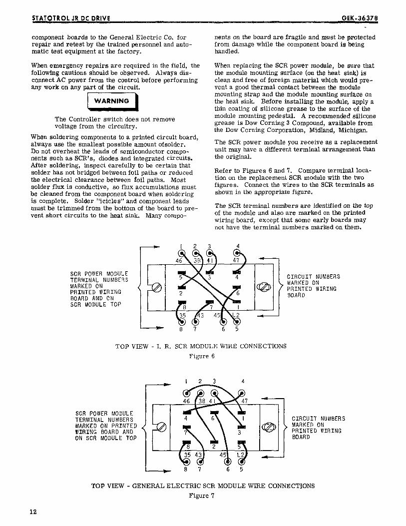
When emergency repairs are required ill the field, the When replacing the SCR power module, be sure thatfollowing cautions should be observed. Always dis- the module mounting surface (on the heat sink) isconnect AC power from the control before performing clean and free of foreign material which would pre-any work on any part of the circuit, vent a good thermal contact between the module
' mounting strap and the module mounting surface on[WA_ the heat sink. Before installing the module, a
WARNING applythin coating of silicone grease to the surface of themodule mounting pedestal. A recommended siliconeThe Controller switch does not removegrease isDow Corning 3 Compound, available from
voltagefrom thecircuitry, theDow Corning Corporation,Midland, Michigan.When soldering components to a printed circuitboard,always use the smallest possibleamount ofsoider. The SCR power module you receive as a replacement
unitmay have a differentterminalarrangementthznDo not overheat the leads of semiconductor compo-nents such as SCR's, diodes and integrated circuits, the original.After soldering, inspect carefully to be certain thatsolderhms notbridgedbetween foilpathsor reduced Refer to Figures6 and 7. Compare terminalloca-theelectricalclearancebetween foilpaths. Most tionon thereplacementSCR module withthe twosolder flux is conductive, so flux accumulations must figures. Connect the wires to the SCR terminals asbe cleaned from the component board when soldering shown in the appropriate figure.is complete. Solder "icicles" and component leads
The SCR terminal numbers are identified on the topmust be trimmed from the bottom of the board to pre-of the module and also are marked on the printedvent short circuits to the heat sink. Many compo-wiring board, except that some early boards maynot have the terminal numbers marked on them.
I 2 3 4
TERMINALNUMBERS _ 4_ MARKEDONMARKEDON 7 PRINTED WIRINGPRINTED WIRING 2 6 BOARDBOARD AND ONSCR MODULE TOP
8 7 6 5
TOP VIEW - I. R. SCR MODULE WIRE CONNECTIONS
Figure 6
I 2 3 4
46
TERMINAL NUMBERS 4 CIRCUIT NUMBERSMARKEDON PRINTED MARKEDONWIRING BOARDAND 3 PRINTED WIRINGONSCRMODULETOP BOARD
_,,. 8 7 6 5
TOP VIEW - GENERAL ELECTRIC SCR MODULE WIRE CONNECTIONS
Figure 7
i2

s_A_oTRotjR,DCD_iVE : ·' _,_...... G,EK-3637
When returningcomponent boardsfor repair,con- RENEWAL PARTStact your local General Electric Sales office for re-turn assistance, pack the units carefully to prevent Replacement parts can be ordered from the nearestadditional damage from occurring in transit, and sales office of General Electric Company, Motorcarefully describe the symptoms which were ob- parts can be obtained from the nearest service shopserved, authorizedby the motormanufacturer.
RENEWALPARTSLIST
FOR3SJRBAND 3SJRC SERIES
1/6 HP THROUGH 2 HP STATOTROLJR CONTROLLERS
IDESCRIPTION L016 1025 1033 1050 2075 2100 2150 i2200OF PART OR CATALOG 11/6 HP (1/4 HP (1/3 HP (1/2 HP (3/4 HP (1 HP ( 1 1/2 (2 HPASSEMBLY NUMBER [15V) l15V) 115V) l15V) 230V) 230 V HP 230V) 230V)
- i ' i ...............
Component Board 44B33§124-G10 IComponent Board 44B336124-Gll 1
Component Board 44B3_6124-G121 1Component Board 44B336124-G13' 1ComponentBoard 44B336124-G21 1ComponentBoard 44B336124-G22 1ComponentBoard 44B336124-G23 1ComponentBoard 44B336124-G24 1Power Semiconductors 44A370660-G01 1 1 1 1Power Semiconductors 44A370660-G0_ 1 1Power Semiconductors 44A370660-G0,_ 1 1Fuse 4 Amp K9774717-9 1Fuse 5 ._mp K9774717-7 1Fuse 7 Amp K97747] 7-10 I 1Fuse10Amp K9774717-2 I 1Fuse12Amp K9774717-3 1Fuse ]5 AmP K9774717-4 I 1Switch* 44A336700-001 1 1 1 1 1 1Potentiometer* 44A335893-GIC 1 1 1 1 1 1 1 1Switch_ 44A336737:001 1 1
* Not used on 3SJRC Models.
I
FOR FACTORY SERVICE AND APPLICATION
ASSISTANCE CALL WAYNESBORO, VA.
703-942-7811
Befor_e calling, list catalog numbers of theController, motor, operator's station andany plug-in options.
13

STATOTROLJR DC DRIVE.... _: ..... _GEK°3637_ _
4 4-7.6V
t_o:E.T f _oTc.
cu_RE.TY T B"EEO'""I
,w _ .L SpEEO_V I
,. ??'t ['Ll..,.II) I I
6
llo60NF _' J RENOVE140RIFOV + S _V 5 (9) (8) (I) [24) LINE VOLTAGE
-- i "· (JO) I FREQUENCY IS 50 HZif:,4 I
POWER Id,-127_r,_ I
SUPPLY . .__86 CUSTOM (7)J g ----CIRCUIT D_ /q_2D INTEGRATED t L ;_0
85 6 _.3 (14) CIRCUIT 'lc)r -- -- ]I_lO0..,q_ J (PINS NOT SHOWN IN O,OER)te¢/gz - -
,i..___4C -4f_ (ri) US) (20)(7 I I_o ,_'l l;r-'[_
"Z I 9 IN('__'4 I j ' J'' L_ _ / '--
_6; 2 ! ,_ ,s "o_ = _c _Bc- ' * _ uSEO IOMF ,OI lCfK_lSIT 8g5K
I 5C 2I ZTC 7'O _ J_,D ON ALL 55t, t." , NOT 00E47.-¢_ OI
(5) .033 50v _4F -- . ON ALL IOMF't' _o,,I B°VlL! I I ¥,,OOELS Irc / /: ,L I FIRIN6 CIRCUIT £ z ,k J. _,. _
ITB-LI ·"'_5_ . ,o4.....¢..I ¢v,,o>. , I:i4
I c,.cu.'r ! f<=_'_l / / / _ .6 ,%r, ],."R_',"ERI J_:",:_,J,4"5/ I"°¢?%-_'_.OTORI s_ · _' 180
t *usEo _."UT /I_%-;'.I% '_°I:;L_I & _.'_,,..¢oNMEc',I I _L-?3 hlb _T-_,._-_ k, toqF_k,'_t:_f,/_¢_,,, _4 / i96R I
I ( I ) _ T r - - i _ I - ITB-A,2
I.... J ITB-L2
-NOTES: - -
I, 'rF ONE SIDE OF AC LZNE 'rs CONNECTED fO GROUNI) 4_ 9';' &: BSR ARE LOCATED ON THE MAX,-¥'rN, SPEED POT ASSEICBLY.THAT LEAl) MUST BE CONNEOTEI) TO ITB-L2,
5. dUMPERS ARE ADDED DURING ASSEMBLY BETWEEN I _, 3 AND 2 & 4· 2, COMPONENTS WHICH CHANGE WTTH LINE VOLTAGE ARE FOR [15 VOLT OPERAT.rON. WHEN BOARD IS TO BE USED ON THE 23S
AS FOLLOi$; VOLT L.rNEt A JUUPER .rS ADDED BETWEEN 2 AND 3 ONLY.I IBV 230V
tl30 & 140 I .2RMF 400V I O. IMF 60OVTm-; I ISK / 30_'T"?2Fi I 2K / J'5_r
3¢ VALUES OF 76_7%150 AND 15IH ARE SELECTED DURZNG
TEST OF COMPONENT BOARD AN_ _ZLL VARY FBOM MD. TO BD,
Figure 8. 8tatob'o! _ Drive, Elementary Diagram
Control Devices Operation and Speed Variator Products Department,General Electric Company, Waynesboro, Virginia 22980
,o_,,,,,,, GENERAL0 ELECTRIC ?14