general electric - store.gegridsolutions.com · miscellaneous troubleshooting --checks ..... 50 7.0...
TRANSCRIPT

INSTRUCTIONS GEK-24997A
AFTROL* I
Adjustable Speed Drive Controlle,I to 7 1/2 lip Variable Voltage
Square Wave Inverter
? GENERAL(_ ELECTRIC
>
(Photo MG-5603-1)
These instructions do hot purport to coverall details or vnrzntmnsm equzpment nor to prowde for everypossible coatmgenc? to be met tn connectionwith
mstallatton, operation or mmntenance. Should further mformat_onbe deszred or should part_cular problem, ar_sewhich are not cm'eredsufftc_entlyfor thepurchaser's purposes, the matter should be referred to General Electric Company
GENERAL0 ELECTRIC*TRADEMARK OF GENERAL ELECTRIC COMPANY, U.S.A.
I, I',k ? IqqT ;%
TABI,E OF (;()NTENTS
I'agc
I 1) Inlroduclion .................................................................. 8
Ihucl Ih.-Iq_l.m ............................................................ 8Standard Features ......................................................... ()
()plional Feature,, ......................................................... 9Adthlmnal Funclions ....................................................... 1l
Input/Oulput Transformer,', ............................................... I l
Input/Oulpul AC Contactors .............................................. 11
2.1) I)cladcd l)escriplion ........................................................... 12(Lmlroller .................................................................. 12
!)(_ l,mk F. her ............................................................... 12
Power Mt)dui(' . ............................................................... 12
(Lmtrol (1,,rd As,.cmbly ......................................................... Ic)Regulator Card ................................................................ 1c)lnw-rler Control Card .......................................................... 22
()perator", !)ex ices ........................................................... 23A(; Motors ................................................................ 23
1)craling I)ala ............................................................. 24
P()w('r Fa('t(,r Improv('ment ................................................. 24,
A,O lC(,,('.wng. II,m(llmg and Sh.agc . ................................................ 20
Ilccciviug ................................................................. 26II,.mll,ng .................................................................. 2()
Sim'age . ................................................................... 26
Safely tor Persmmel and Equipment ............................................ 26
I 0 In,.lallalion ('.uldchnes ......................................................... 27
(;eneral .................................................................... 27
Mounting .................................................................. 27
Wclghls and l)lmcn4ons ................................................... 27(Smnccti.n,, ................................................................ 27
W.'mg Practwe,% .......................................................... 31(]odes and Slandards ........................................................ :Il
Power V¢]ring ............................................................... 31
(.otttrol Wxrtng.............................................................. 324(; Motor'. .................................................................. :_2
{)pcrator"_ SIallon ........................................................... 32
5.0 In,qwclmn, Startmp and AdJustments ............................................. 33
[tut mi In.peclmn ............................................................. 4.4
NI,II l-Ii;_ l)roccdt.[ cn .......................................................... 3,1
,\dj H',l I11('111 S ................................................................ i_ 1,
;\dlu,_lmcnl Rc,'-rd_ ........................................................ 16
50 ttz A(_ _upply ()peration ..................................................... ?,6
6.0 Troubh',4.mllng Pr(.'edure_ ..................................................... 37
Te_I Equlpmenl Required ..................................................... 37
'Fe_Img Safely Precautions .................................................... 3?
(;eneral Troubleshooting ...................................................... 38(]ontr_dhq Shul_ Down ami ('.annoI }r' l'le,qarled ............................... ;'18
('.outr,,llel ()perale_ Improperly .............................................. 1,3
)

GEK-24997A
TABLE OF CONTENTS
(conlinued)
Page
Tr(,ubh'sln,(,tntg ( ]ha,'l ......................................................... 40(kmtrol Card Troubleshooting ................................................. 45Power Moduh'Troubleshooting ................................................ 46
(;onve,'ter Section Troubleshooting ........................................... 47
Inverter Se, tion Troubleshooting ............................................ 48I)C I,ink Trouhleshootiug ..................................................... 49Miscellaneous Troubleshooting -- checks ........................................ 50
7.0 Removal, Repair. Replacement and Maintenance .................................... 51Regulator/Co,_trol Card Assembly .............................................. 51I,ower Barrier ............................................................... 54
Capacitor Ass('rnbly .......................................................... 54Power ModuleSCR Bridges ................................................... 55Power ModuleTranststors .................................................... 56PowerModuh,Card .......................................................... 57(]onlrol Translormer ......................................................... 57
Power Moduh.Assembly...................................................... 57(',hoke Assembly ............................................................. 58To I) Barrier ................................................................. 58I:elrile. Core Reactors ........................................................ 59
Fan Assembly............................................................... 61()pi.mai Rev(.rsing and Follower Cards ......................................... 61
8.0 Slandard Specifications, Options and Operator's Stations ............................ 63Itorsepower ................................................................. 63PowerSupply............................................................... 63Power Output............................................................... 63
hq)ut Full I,oad Amps ...................................................... 63Output Full Load Amps .................................................... 63
OverloadCapabihty .......................................................... 63Speed Range................................................................ 63ServiceCtmdil_ons........................................................... 03I"unctn)ns of Basic Controller .................................................. 63
SpeedRegulalnm ............................................................ 63(;urrent lam_t............................................................... 63
,\dj u,d menl.; ................................................................ 67_I)rotect_ve Features .......................................................... 63
Operator's Station ........................................................... 63
Ol)tlons ...................................................................... 63I)isconnectSwitch........................................................... 67
AuxdlaryRUN Relay ........................................................ 67Speed lndicat.r ............................................................. 67Motor Ammet(.r ............................................................. 67
Instrument Enclosure ...................................................... 67
ReversingCatd .............................................................. 68FollowerCard............................................................... 68
Operalor's Stat,,,n,, ............................................................ 72

¢;kk 2 1_;c)7\
'I'_,,BI,I_;()1"(:()N'I'I,;N I'S
(4,(mlinl..d)
I)ilg( ·
_DO .Si.aleami I'h'm'w,LIP,u'I'., ....................................................... 7'_I)linled I]]r('utl I:olds ........................................................ 771
:":,ub-a,,,,emtfile,,and (]omf)om'nls (nol tip lelaled) ................................ 77,Spare and Renewal parts (tip related) .......................................... 71t",.ld Modifle,ati(m KBls ..................................................... 75
II()T I,INE TI':I,EI'HONI_: NI.IMBER .............................................. 76
(;h)ssary of Term ............................................................. 77

(;EK2 I.q()7\
Hiiim mi I I I I I I
LIST OF ILLUSTRATIONS
Igg,Hc Page
I ,_l,'t,ol I (:,mf,'ollcr. ,hmr dosed w,lh d,)or mmtil'wati(ms ............................. 8
2 Al"tmolI (;onlroller, door closed wfihout door modificatmns showing rear ventdated
(.om part me, lit ................................................................. 8
3 ()peratm"s Station wi[h Man. Auto Selector Swilch ................................. 9
4 Aftrol I Mo&fmation Kits left to right: Follower Card, Reversing Card,AuxdmryRun Relay................................................................... 9
5 Al"trol I Controllel with I"ollower Card, Reversing Card & AuxiliaryRelay Modification Kits installed ................................................ 0
() 41"til)l I optional bt)('ed Indicator and Ench),,,urc Modilicaliml Kll ..................... I0
7 Al"tr(ll I (:l)nfrolh. t -- Wall mounted (enclosed) ve,'smu wilt) door modifieatmns ........ lO
7/\ ,'\l"lrol I (:onlrollcT -- (:hassls mounted (open) version .............................. I0
8 Al'trol I System I)_agra,n ....................................................... I1
l} Power Module &I)C Fihcr Elementary DiagranlI & I 1/2 tip Single I_hase. Input ................................................ 15
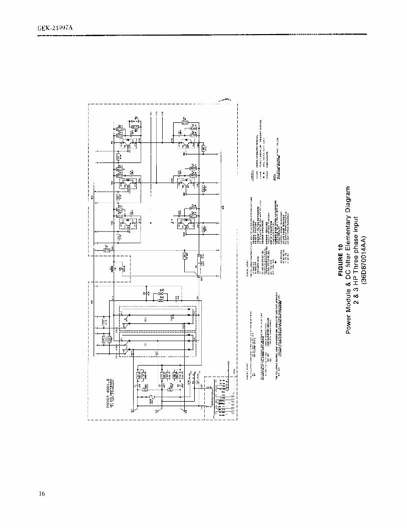
I0 I)owcr Module & I)(: F'dter Eleme.ntary Diagram'2 & 3 lip Three J'ha.,c hq)ut .................................................... IO
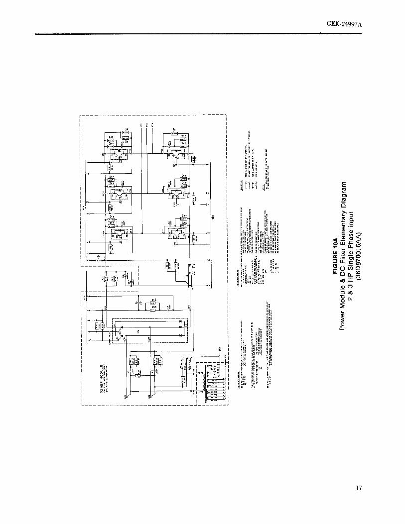
I0\ I)owm M(Idulc & I)(; Fdh,r Elemcntaly Ihagram'2 & ?, lip Stiigle I'hasv Int)ul .................................................... 17
II Power Mmluh, & It(] !"fher Elem(mlary I)iagram5 & 7 I/2 ItP 'J'htee Phase hq)ut ................................................ 18
15 Operator's Slart -- Slop Control Oplions .......................................... 25( _,I))
il) ()lllhlie I)rawlng, '\[Irl)l 1, wall iil()Ulilt_,d .......................................... 2g)
17 (tull)nc Drawing, M'I,'()I I, (;hassis Mounted ....................................... 30
18 Al:frol Clmfloller I, door ()lien, showing close uI) of 2'FB terminal boardpmnl 22 and ground conne('ln)n ................................................. :gl
Iq Mlll)i ('.onl,'.lh.r l, Ir(mi [)am'l detail,, ............................................ 30
20 ,,\ttrl)l I (',()ntrolh,: -- I'h,guhltor/in'_(,rlvr (:onlrol cards showing removal of(ii' rlbb(in cai)h, ( ()linl'l'llIrs ..................................................... 5l
21 '_l"l,,d I (h).holl,'r. -,h(iwing Iht I(m,,cnntg id 2'I'll Icrmin,d st,rows Ihal Il-hi
Ibc Ih,guhitor/In_crh,r ('.onl,'ol (iai'ds iii place. ..................................... ."')2
22 \l"liol I (',,mil.ih i, ,,bowing Ihc rc,lh.;)_cof Im_cr I,Ih'hc'. or! Ihv Ilcgul;itm'/Invcrt(ut',()lllloI (',HI'il \''"mhl_ ......................................................... ;2
5

I,IST Ill: II,I,tlSTRATI()NS
O'ont,nued)
hgmc Page
2.-I Alqrol I (kmtroller, showing the Regulator/Inverter C.mtrol Card be, ng lifted up.Note conue_ tot 3(',N that connects tile two cards together ............................ 52
21 Al"t,ol I (',ontrollcr, showing latch ilar m retracted position .......................... 52
21\ Al"Irol I (;onlrollcr, showing the Regulator/inverter Card in the latched up position ..... 53
25 AFtrol I Controller, showing removal of plastic wire support on Regulator/Invertercm_trolcard agsemhly .......................................................... ,q3
2f_ AFtrol I Controlh,r, showing withdrawal of Regulator/Inverter Control Card Assembly
horn 2TB ternmml board and slotted hinge holes .................................... 53
28 AFlrol I (]onlrolh,r, showing removal of nuts holding the lowerplasticbamer m place.......................................................... 53
28\ Alqrol I Controlh.r. showing removal of lower barrier on chassis mounted umt .......... 54
2_1 AFtrol I ('ontrollc, r, showing the lower plastw barrier removed ........................ 54
::;5 Alqrol I Controll,_r, showing capacitor assembly with two capacitors ................... 55
3(_ AFtrol I Controller, ,,trowingthe capacitor assembly removal ......................... 55
37 AFtrol I Controller, showing the capacitor assembly removed ......................... 56
38 ,\l:trol I (_ontroller, showing the removal of the SCR bridge modules from thcIhe Power Module............................................................. 56
38A Al"trol I Controller, showing the removal o{ the power transistors from thePower Module................................................................ 59
38B Alqrol I Controller, showing the removal of the Power Module Card ................... 59
38(: Al:lrol I Controller, showing the Control Power Transformer removed from theIh.werMmtulc. ............................................................... 6()
381) Al"ltol I (]outrolh.r, showing Power Moduh. wtth plate healsink (l lhru 3 liP) ........... 6(1
38E /\Fllol I Controlh,r, .,,bowing Power Module with exlruded heatsmk (5 and 7 1/2 liP) ... 60
38F 4["trol I (]outroller, showing removal of ('hoke assembly ............................. 61}
38C 4Ftrol I (',outroller, qmwiug the choke assembly removed from the controller. .......... OI
II _l"lrol I (]ontrolh.r, _,howmg tile removal ot Ihe upper plastw barrier . ................. 61
12 \l"l['ol I (retire.lief. vvil}l i.iq.,r plaslw }}dr]ltC] removed, exposing Ibc choke as.emblvami h', ,Ele ,'ore ,ea,'t,,r.. ........................................................ 01

(;ICK-2I,_)_)7,'_
LIST OF' ILIAISTRATIONS
(continued)
Figure Page
43 Ventilating Fan Assembly for 7 1/2 lip (kmtroller.Note the copper case grounding connection ........................................ 61
/1./I. Opt,on Kits ................................................................... 65
45 I,ocation of option Kits ......................................................... 66
46 AFtrol I ('ontroller, showing Reversing Card option mounted oa Regulator Card ......... 69
/I,7 AFtrol I Controller, showing Follower Card option on Regulator Card .................. 70
48 AFtrol I Follower Card, Gain and Offset Characteristics .............................. 71
'I'AFI{,I']A Base Frequency lumpers ........................................................ 35
'I',XI}I,EI_ I"olh,wcr Card ,l,,mper connections ............................................... 70
GEK-24997A
.Ill
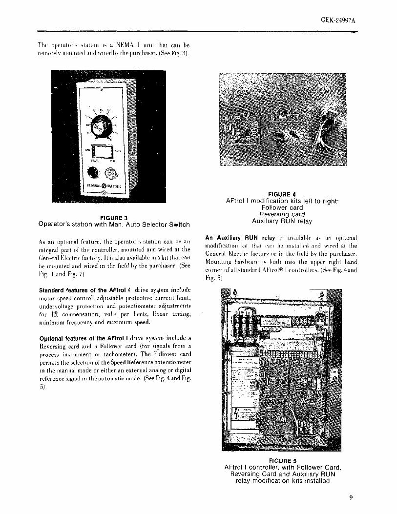
The opelalor'_ ",[dtltHl 1_ a NEM& 1 unit that can berenmtelv nl(}unled and wned b} tile purchaser. (See Fig. 3).
FIGURE 4AFtrol I modification kits left to right-
Follower card
FIGURE 3 Reversing cardOperator's stahon w_th Man. Auto Selector Switch Auxihary RUN relay
An Auxiliary RUN relay 2, avadable as all optionalAs ail oplmna[ feature, tim operator's station can be an modification k.t thai can l,e m,,,talled and wired at theintegral part of the controller, mounted and wired at theGeneral Electric factory. It ISalso available m a kit that can General Electric factory or in the field by the purchaser.be mounted and wired m the field by the purchaser. (See Mounting hardware _, bufit into the upper right hand
corner of all qandard ,\lqrol® l conlrolh'_ ,,. (See Fig. 4andFig.1andFig.7) lqg.5)
Standard _eatures of the AFtrol I drive system include
motor speed control, adjustable protective current hmlt,undervoltage protectmn and potentiometer adjustments
for IR compensatmn, volts per hertz, linear timing,minimum frequency and maximum speed.
Optional features of the AFtrol I drive system include aReversing card arid a Follower card (for signals from a
process instrument or tachometer). The Follower cardpermits the selection of the Speed Reference potentiometerm the manual mode or either an external analog or digital
reference signal m the automatic mode. (See Fig. 4 and Fig.5)
FIGURE 5AFtrol I controller, wath Follower Card,
Reversing Card and Auxflmry RUNrelay modd_cahon k_ts mnstalled
9

CEK-24997 &
\ .[,i .,_l lllth(,ll,. .- al.<* a_a,lablc a_ ,m .ptmn_l
m,.Jl{Itall,,u {%,c Jig h}
FIGURE 6 _'r
AFtrol I Optional ModJfication KitSpeed Indmator and Enclosure
Thc &l"tlol I c<mtroller t- avallab[e as au "o}_en" unit
',tutable f-r pa_leI mounlmg reside a ktrger em h_.,ure that
may e_mtmu other electr_<'td apparatus furm,_hed b)
(;enera] Eleclrt_ (]ompanv or by the purchaser (See Fig.7\)
FIGURE IA
AFtrol i, controller, suitable for "open"panel mounting
FIGURE 7
AFtrol I, wall mounted (enclosed) version)
10

GEK-24997A
ADDITIONAL FUNCTIONS
INPUT/OUTPUT TRANSFORMERS
hipnt v()hagc ,equnements for AFlrol I controlh;r,, are230V A(] Jrtall cas_'s, single or three phase, 60 or 50 herlz._'hcn 230V AC ].',not ava,lable a voltage translormalmn 1.',,,'(',h'd. 'l','ansf()rnler KVA ,e, lui,ements are as h)lh,w,,:
230V AC Sin_h' I_'ha.,,c 230V Ali Three l'ha,,,ei
lip I I I/2 2 3 2 3 5 7 I/2
Inpul IxVA 1.6 2.3 3.2 I,.0 3.0 4.1, 0.8 8,8I,putAmps 7 10 I1. 20 7.5 II 17 22
If 230V 4C motors are no! avafiablc, ar, .ull)ul voltagetrau.,,fi)rmation ,s required.
Refer Io (;encral I';leclr.' (;mnpanV. Application Maliual,(;1';'I'-6{)5() or you ,leale:-,t (;choral Eh'cir.' (]omi,anyrcl.('.-,('nlalive for ,t_mMam'e],, the _,ch'clm]l()1Ihe l),Oln','I,I[IUI ()l ()tllpt]l [,ll,l'-,[Olll,(q's.
INPUT/OUTPUT AC CONTACTORS
\[! Al: hH¢, ('ol,l,I('lo,' ,s 511)1 tt].ni.,,hed wilh Al"t,ol I
( -nlroih'r.., II an Ac('()l,la('lo, I,",dc-,u'ed ,n the hne ahead olIii,' ('(),]lrolh,r m' l)(qwccn thc ('()nli(dl(',a iici Iii,:' ,,,()1(),,iii
Ibc i.u,cha_cd I1'i1_ add .uch .. ('O'llli('li)' ($) I)ll[ .].,,.hl I,cgu.lcd b., Ibc ,nhn mal.m m the apphcat,.n Manu.il (;FJT-(_()5¢).

(,EK-2_q97A
SECTION 2.0 },tale, ul,,,ulated lmm Iht' powcr {'llCtlll 'qt_ that file',, call l'le
ill(lllrll(,d (Ill a eOflllll()ll htr:if sulk '['lit' ex[el ns1 (,(nlne('lit)tlS
DESCRIPTION t,, *lit, p.wcl ..,d.h' a,e showu .il hg. 8
,'_1"11.1I ,h_v.' ,,wle.i e.n,sLq, .I the AFtlol I (.mllrtdh.i. Thc l.,wel ,nodule ,'a. be funetu.ially broken d.w. ,.t.
,.mlaldc (q..]alm's devicc,., alu{ an Al: nitili)r. The Iw. ,q,cteorl,,., Ihe c(mvertel sechon and the reverter.uliollcl ('()t,s_.t._ of,',everal rnotJuh's and a_,,emhlie,,in an .cci.il,. The ('tmverter set'tlOn eon,,,ist.s (if the S(]R
em'hlst.r.. 411 td these parle, of a representative drive converter module,, and tile following [noteet,ve
,.x_,lem iucluduig available optmn.,, art' show. ill block conqmnents tin lite power module card:.h,lgram Im'm ill Figure 8 (361)87008AB).
CONTROLLER
1, A nletal oxide vanator (MOV) is connected across
The AFIrtd [ eonholler rs a var,able voltage, square wave each AC supply phase pair to ehp transient voltages
u, vel lei, wi, u'h convert,, a ('o.stant vtlltage and frequency to a level which will not damage the converter SCRs
'hi, supply hi ,all adjustable wdtage and frequem'y, three-
[dhlSe At' ()Itt[,ut. The speed ot lhe eonneeted At] motor will '2 llesJslo] -- capacitor circuits are provided aelos-
tit, th'pendent .n the tlutput frequency of the controller and each 4(1 supillv phase [lair, aud across the t'onverte; _
the tllolol tolqlle wdl be depcndent on the (Itlt[lul vohage DC output, to sup[tress transient voltages and hmilIcw,I. Thc controller adju,;ts the output wdtage and dv/dl m coujunctton wlththemcomnxghneferrm'
frcqucncv hlgcl her Itl provide constant vohs per hertz, over chokes.
ltt(Isl (Il the operating range, for optimum lllO[Or
pcrh. manic. 3. A power resistor is t:onneetcd acr0sq the eOllvertei
D(] output ti) discharge the D(; hnk fiher eapacil.I
Thc _;u mu,_ psi'Is of Ihe em]trt)llcr are described below, ri'his resislor is rated ltl eau'_e lhe DC hnk eapac'lhll
to disc}large fi oni maxunum voltage to 50 voh'_ uINPUT PROTECTIONS one nuntJtte
Tile 4(; ,.uppl_ input ,'oustsl. of a lwcl wilc ,,ingle ph.lse.n[n]l hi, ] thlU 3 lip ,,,igle pha'.e IIl[.Itll c'tnllroller_, and a The function of the eonvcrh'r section SI;l{ nlodulcs is tc
Ih_m' wu'e Ilut'e pha-,c Illptli tt)r 2 thlltl 7 1/2 lip thr.e i'm)yeti Ihe AC supply power to adjustable vohage 1)(
tdue, c luput (onlrtdh,rs Shuidard 230 voh fuses arc power al point PI hi NI (see Figs. 9, IO, IOA alit] [Ii.ltl(,Vialed [(ir ,.,,hi]il t'll('llll prtltt*t Ill)fl At [elrlte choke ,..
,i]clmh,d lu ea,'h '\(] ,,upplv liuc t- protect Ihe c'onlrtdh', The Il(] Oil]licit voltage id' tilt' ctmverler can Iii' ,Idju.h'(
ff.nl ,,oltage tlal,'-,lelllS that may clt'('LIr Itl Ibc powel trlllii zeru It) maximum outt)ut by adjusling lhe tiring limn
,vstelu. ol eac'h bl]R relative lo its All supply vohage Th]', filin_
((mh()l ms contained on lhe Regulator card, and ,,DC LINK FILTER Iram, nnth'd hi Ihe Power Module through ribbon ('ab[(
I.(;N Tlua same cable also lran,4mlts the DC hnk voltag(
Th,' Il(; link H[el c(nl.,i,,Is ot I (ir 2 il (Ill ('ore rea('tt)rs (1,1") feedba( k signal back to the Regulator card where ,I rs user
.uld I ti, 2 c,]eclrolyh(, cat)ac'ltc)r ((iF), de}lending (nj tile to legulate the converter output voltage to vary d)recll?
.'.nll(dh.r })(ll.(,l.lWel taring Their little'tit)fl IS ti) idler the wllh lhe inverter output £reiluency
t}lll[},ll t)f' the (()))'_('rt(') t)t'fole it l,, ai,plied ti/tile lllvertt'l'
i'hc (3: catulclh)l also ac'Is lo s.[)ply rea('tlve [)()wer lhrt)ugh Thc ('onverler cmtput v()lhtge c'ontain., appre('ml)h' rqq)hIht ulvcrlcr I. Ihc Al' niohlr voltage wlit,'tl llltl",l lie filleted by Iht' I)C hnk tiher.
POWER MODULE
The pt,wel re.all.l(' a_,.e.lhlv (c)m,.qs ()1 I (Il '2 .SI;l{
,'till'vi'riel Ililldil_t'.'.,,, power tl'all'-,l'.,lOl s4, ])owt'r lllodtl_e fill C{
ami ('(,ntrol Ir.tn,,h. me] ;ti[ n.lunfed on a single tlealsmk
Thc ,.,i.gl(. t)h;t_e tnf.,I c'onhdlers have I SCR converter
)ri,dub, and Ihe lhree pllas(, mpul eclnlr(lller,,, have 2 S(]R, m),.,.lh,l re-,bile,. (',ce Iqg'4. q, lO. lOA and 11). The ,",(;R
cemt('lh'f mmJtih-.-, alld [)()wer Iransl_tors have Iheir [la',e
12

" (;I.;k.2 l.g_)7\m mm m
The lllVprler st_('JlOll ('Ollhl,_Js ()f' Ibc ,_lx powJ_r Irall%l',l()l'_
'which form a thre,' phase bridge and the f(lllowmgcomponents on lJle power module card:
1. Reststor- capacitor mrcmts are prowded acrosseach leg of the reverter to assist transistor switchingoperation.
2. Transistor base resistors and printed circuit runs tothe 5(]N and 6CN connector.,,.
The functmn of th_, Inverter Module power transistorswttches i,, lo converl the adjustable vohage DC link poweral points P2 to N2 (see Figs. 9,10,10A and 11) toadjustablefrequency and w_ltag_'AC power to drive an A(] motor. TheA(] outpul of the inverter can be adju,,ted tr(mtapproxlmalely 2 Hz, depending upon adjustments on theRegulator card. The three-p}mse transistor base drivercontrol tn contained on the Inverter ('ontrol card, and tn
transmttted to the Power Module through rtbbon cable,,5(iN attd 6CN. Cable 6CN also transmits back I)(i hnk
current and vohage ,,ignals to the Inverter Conlr{_l card.
The power module card is a printed circuit card mounted onthe power module heatsink. In addition to the items
spectfied under the converter and reverter section, thepower module card p, ovides the following components andternunations:
1. Terminates the connections to the converter
modules and power transistors,
2. Provides 3 A(; input connections for 3 phase inputcontrollers or 2 AC input connections for singlephase input controllers and 3 AC omput powerterminations.
3. Provides 2 AC connections for the primary of thecontrol transformer and 3 connection points for theDC Link Filter.
4. Provides connection points for the 4CN, 5CN and6CN ribbon cables,
5. Mounts the DC link shunt connected between
negative D(: link terminals NI and N2, andtransnnts the shunt vohage signal thru connector6(;N.
13

-!
=
J_ ! !
r__T
-=,
r
_F
US
EI
,LS
LFIT
B
_,,_
-_[..
......
......
.il/
'ii:
F_
9R
C_T
_OL
_B
_WE
_NT
E".
J.A
LP
O_
T_
TD
TC
N
:-_--_
rs££
,_sr
aoax
Fo.
PO
T_JU
_tU
E.T
I
RU
_JO
_O
_TI,:
'.Il m I ! im
FIG
UR
E8
AF
trol
ISy
stem
Dia
gram
(36D
8700
08A
B)

%I
I_
,_l
=..,
IL
----
'_'-"
----
--'_
--'l
,_
[II
_OU
_,C
L^T
UR
E_O
_E_C
LXT
U.E
R9
TO
PR
OV
_O_
10_
_]LM
VO
LTS
_RO
PA
ALL
RE
_[S
TO
__
I_ffA
TT
UN
LES
S
_CO
UT
PU
TP
OW
_T
ER
M[N
ALS
FIG
UR
E9
,_P
ower
Mod
ule
&D
CF
ilter
Ele
men
tary
Dia
gram
I&
I1/
2H
PS
ingl
eP
hase
inpu
t(3
6D87
0013
AA
)_;
>
!
,_.
i[
:=..
....
II
II
II
II
[- I I
FI J
_9F
:LT
Ea_
*CItO
RD
l_._
_£S
_ST
O.
_S-S
,.._C
O.K
EC
_O.
_ER
U:.*
L
I !
FIG
UR
E10
Pow
erM
odul
e&
DC
filte
rE
lem
enta
ryD
iagr
am2
&3
HP
Thr
eeph
ase
inpu
t(3
6D87
0014
AA
)
II
..,,
,4
s?5
,2'
I
_,°,
_°,_
%_o
_I
_,,._
,_
_'"-
_'-
-'"_
'II
2uF
F?_
--i
__
rT_j
-l=
d3_
rT_
I
]_
I.,,
I...
.I.,
;...
.]-
,
....
L..
..J
I
--
3j
] I I I : I I
,I j
L--
-/
_Oue
rcLa
Tu.
£_O
u_.c
u^tu
rE
_,]
-Tra
,s_;
.tvO
Lta_
£suP
Pre
ssO
r-r
LTE
fi¢_
aC_T
ORO
]s_G
£R
EsI
sTO
Rs
_P
Ow
SrT
£Ru[
_O
_TR
a_sl
sTO
nTS
r_l_
aL
TII
T21
T31
t_l
tS_T
_IP
OW
ERTR
ansI
stO
Rs
r_2
r_z_
3_2
r_3
-s_u
_£r
res
stO
Rs
_lC
rw
]_e
_£_
-cO
ntrO
LT
.^.s
_Or_
Er
r_l
r_2
scr
oAt_
r_Is
Tor
s
aLL
r£s_
stor
s_E
I._w
^_ur
L_ss
OT
HE
rw]s
_sP
£c]_
r£O
T_
T2
t3ac
Out
PuT
PO
w;r
T_r
ur_a
tsK
_ac
_rP
uT_O
w_r
TeR
_I.A
Ls
FIG
UR
EIO
AP
ower
Mod
ule
&D
CF
ilter
Ele
men
tary
Dia
gram
2&
3H
PS
ingl
eP
hase
inpu
t(3
6D87
0016
AA
):>

'42,
---.I
r
poP
hEF
tM
OD
ULE
,_,
,o,
,_,?_'-'""-T
]
ii
1
......
ic.
II
i..-.._
II
iI
''
iI
I
II
c__
II
....
II
II
[I
?i
....
I1
I1
II
--
II
,c.
mo
LJ
IlL----
t_J,
.....
Lkk'q_
e,q'4_
.O.E.CL^TU.E
.O_£._TU.E
fop_
o_[D
Ei0
0_[
LUV
_LT
5_R
OP_
T
_,,'&
%....
........
........
..
I ! I 1 I
FIG
UR
E11
Pow
erM
odul
e&
DC
Fil
ter
Ele
men
tary
Dia
gram
5&
71/
2H
PT
hree
phas
ein
put
{3gD
8700
15A
A)

(, EK-24997A
i . i
CONTROL CARD ASSEMBLY ?, I',nth I,,,g,'
Tht,, ,m a',',entblv t}t* Iht Ih'gulan)r card (tm lop} and Ibc (.Ollldlll.-, .I lauh Iai, h t&hn.h i _,_,cl I,_ ,i I,mll ,.i,.mal
I,_,erl{'r (:mHrlll card (ira Ell}Il(ifil), which I', mom{foil tn the Iransnllll('d Irl)nt Ill(, li,,,(q h'r (i()llll()[ i ,,Ill Illl ,:tlgl:
i'()lllllillel Irlmt ('()llltl.'iilillelit. Tin(".-.{' two ('drd'-, die ,itl I)l)ll*',t] I',llldlill, (n Ir(mi ii Imiltl)l ,llnlCl,,**Jl,lgc
clcctt'ically connected thtmtgh ttbl.)n calllc 31 iN., i,ll Iht I'h'gut,tt(:r ('aid. Il .l lauh '.,et-, lilt'-. I,tll h, II
III] I1_ -if Ih(. I'l)llV('l I1'1' ,llld Ibc :.x'cl Icl, al,l.l... Ih,
REGULATOR CARD (-,re Fig lq. ILugc39} rcfcl<,l.'c cia.: I) ii, t,,.,,IIhl' t :,nlJ(d I_J /cl,. ,ll.I
dll)[)', ()tll Ih(' (,pli.n,il It{ill i'c],tx, ti I:B.._:.l('d I'hc
Thc Itcgulator i'ard ctmtain.'-, 22 card hngm's which c{mucct taus lah'h ('ann(ti bc rr.cl mild Ibc I,mh c,mthlt.nIt. tlw 2TB control lermllml board, ,md ,:re the cmilr()l i,., iCln(,vc(I, and Iltc I)1'. htlk v(.Ihtgc I_, m',. Il,.
it:h,rhwl, Jletwecnt]WOl}erator'.,,devicesanttlhecontr(dh'r. intnnnunl. To re,-,cl lilt' la{ill lan'h, thc Shq.
Thc illq}e) halt .t tim, ('ar(t, adjacertt lo lhe cald fingel,.. ]Jtl.,h[itllh)n mu,-.I }}c i.ic-,,..cd, .] Ibc i llll lllhq lin Ix('Oltlalll,-, operat.r's control log.' and regulatnig ('ir('ullr;, -I.em.(J, alhq wh.'h thc .re:ti (,Ih'g ma/bc l l.,-,I,iilcd.
amt LI.',iOlltlilt)li is connected Itl case groulld ]brough car(t (()n .,tllglc-ph:.l,-,{' input cottlr,llh.rs, tit{' SI'\\ t.
hnger 22. {/'he lower halt ofthi., card contain'., Iht convert(.r S])X c,ird po,.l', illilzl Ill. juml.(.rcd I. pr(,', .'ltl Iht
control, wluch operales at the posmve 1)(: link (PI) power ,tttdcl v(dlage hnth ('lr('llil ()it Il.' In,,(q Icl (.4)ll[i (.J
potcnlial. Signal isolatmn [_etween l|':e convcrhq (.onll o[ card Irom dch.('lit]g d h..,. mt (mc pha..(,. Thl-, lunq.'lami the regulator control t,. provided by optical {'oupler.,. (,-,['at'l{}r5 tn,.tallcd.
The control power to both halves of the Regulator card Is.lllained from two isolated secondary winding.,, ltl ti: IT\ 1, fhm Rca(hint
c.ntrol Iransformer through cable ICN.
\ green "Run" light nidicale.-, when Ihe ('tmltoih, r
The operator's control arid regulator porhon ot Ihe I', i)[)elatlllg aiid i_ ()El '_vh(ql flit. ('(ml:.ller i..R('gulalor card provide.,, the h}llowing functilln,,: -lOllped. When .i..lall.g. Il blt.k,, ar flit, mvcl lei
llliilllYllllril tieqtlell('t'. The I'h;gttlah)l cald (lullml h:
2'1'11hq'nnnal,., 20 {I)l)",) ,Slid 21 (neg.) Ina,_}lc u,,cd I.
I. F'ower Supply ptt'k tql thc 2t..voil coil ti( the .pttoual Run relax t,:
llldic:tlc wheil Ihe c.nlt.)ller i'-,()pcr.lllllg.
(]Olitailrl.S a regulated +12 voh alii{ -12 volt dual
power supply relative lo the common bu,,. conne{'led 5. Speed Ihqei em'e Adju.'.ltlnel}l
to card finger 22.
Thc op(:,rah}r's :.[leed reference potent i(:llleler (50002. Start-Stop Control ohms, 1 Io 2 wall) i'., iOliliecled lc) Ihe I'h:gulalor
card at 2'1'11tel ntnlal.', 17, 18 and 19, with Icrnnnal
Operator's start-stop control of motor operation 15 18 being the relereni'e inptll. 'l'lle
provided by logic circmtry. The 24 volt i)(: ('{mtrol MINSp. lentiomctel on Ill{' Ih,gui,lira card is usedpower Ill the Start-ShJp pushbuttons (see Fig. 15) ti) adju.st the IIlilUlllillll Ol){'r.Htng ,,I.'ed (al /l:r,
(or It) a run mlerlock) Is provided fm the +12 volt ,,ellntg ol liw .pt:ralol's ,,pced poi) (it Ih(. Ili()liil
and -12 voh card powt'r ,,upply. Tin.', same c. ntr.[ limn tel. It) ;q)proxlln,ih'ly 1,0% I1 i,tlcd. Th('
power is ,ti,',{}provided to the Rever.,.ing and MJ. liu;,d- ,_/ff,,_,li[,_ptdcntt-nteter mi the I'{cgulatm' c,ud i,. ii-cd
Auto optllm ,.witches when l)rovided. Thc st.il l-.,hip h) a(lju,,f lhe lIIaXliiIlllll iqiel',ilillg .l.,cd (,il
log.' alh)ws Marlllig Ihe ]lit)lo{ only ;il Illllllllitllll Ili,lXlllllilli ;-,(qlllig ill lite i)l)cr,lh)l ',l, ,,i,,,cd pi)l} [),l-c:l
Irequen('y an(| vol]age. 'When ]he Sit) I) l,USh})ull-ll i)ll Ibc [,llc:l In:,h. lllqlll('llt't -('Ji'i In)Il
I _, pt {'.'-,,'.,,ed, of Iht' rtltl tttt{,l'l_w[x t}peil,-,, thc ,.tarl-,.l(}ph}gl(' ('l,lntl)', Iht rclercnce h) zero. i.()(lu:'tng ,i
lin{cd de('e]{q',lll()II d(:wIt h) lllllllllllllll freqll('ll( V
anti v.lhigc. :it whlch l:(:iltl ]he E(mll.l].q I.,
.,l.[qled. In thc .,l()lq.'d (qHIdill()ll, t}ll' ('()il'V(q'|(q I':',
lilrll{'d .It attd thc illt{'ll(q I", dl /er(} II('l[tl('ll( %
19

¢-
GEK-24997A
' T_r r
(7. Tuned Acceleration and Deceleration Base Frequent ,, Jumpel Selectmn
Thc l.felentc lirnmg circuit trandates a step 50to 70 Hz None
vhal]g(. Ill rci'erence Input at lerminal 18 iIltO a 60 to 85 [tz BF1 to BF2
lira.ar lallll, change .t reference to the ctlutrollel. 75 to 105 Itz BF2 to BF3
restlllltlg In ,I hlu'al [am t) change in nlolOr speed, lO0 l- 130 ttz BF1 lo BF3h.lh ,. teler,ltlllg and deceh'ratlng. The Ilnilllg t,'.,
adju.',lable, [p, lilt'ails ,ffLTIM polentlometer on thc Rcn]ove the spare jumper lhat is ('re.lei'ted It)card
Regulatol c'lld, troln a llllnllnlllll t)t approxmlate},_ 2 posts I,MN and I,MP to make tlle above jumper..ecrus(l,,, to a IllaXlllllllll t)t' 20 iO :_(1 SCl'()liltS. A "'st)fl Slqccti.ns. The al,.ve sclecli.ns shtmht t)e
slarl" Icaiulc t)rt)vidl's a siowel initial rate ot del)endenl Orl (lying to keep Ihe (a['d ternunal lgtl)accelcralmn when fast timing rates are selected, 22 ((;OM) reference voltage, at maxlnium
[,ongel accchq'ation/deceleratio[l times can be operator's speed potentlometer betting as close to
ol)tamed by soldering an electrolytic capamtor 7.5 volts as possible, and within the range of S.0to
aclos_ card },.st,, TCP (po,,) and TCN (neg.). The 8.5 vohs.folh_wulg tm'mulae fin' calculating the minimum
aild lllaXllllUlll LTIM pot setting time,,, can be used 8. Voltage Regulatorto select the amount of capacitance needed:
The vohage regulator comparc,_ the DC link voltagefeedback signal from ail mlpcdance isolalor en'cult.
TInin, = (25 + (:) x Vref + .5 seconds (±25%) to the vohage reference from lhe lmnng circuit andproduces a converter reference, signal. This signal l,,,
125 sent ti) the ('OllVtq'ter ('on[rid thlough an .ptical
isolator The v.hagc feedbat k ,,iganl is mod]fwd tiy'i'm,tx = (25 + (:) x Vret seconds (+ 100%.-30",) (lie ,,citing of Ih(· I//ll_ p-tenmmleler .n tlle
6 Regtfiato[ card, dependent Oil the reqmred vt.hs perhertz for the At; nl.lor being used. The range .f
v,hcl(. (: = capacltancc irt MH) (25VI)C rating) adjustnlenl ot V/Hz Is cah'tllaled tls billows:
I:e[' = Illax, rel'tilellce voltage at ternnnals 18 h) 22
((:()M) (5 I- 1'1.5 volt',) Vac = 20 x Vi'et (±1.%) for min. V/llz setting
Vat' = 52 x ¥ret (±10%) lot nlax V/H!,,ellingwht,re _ac = A(: thC,lot rrm, vohage
7. Vt}It,Igc Io ["rt.quen( y (),,cdlato.' (Vt:()) \ ['('Il = Il{Itel[ii'Il{l(]voltage tit terminal. 18 Itl 22
The Vt:() ,hanges tilt' reference voltage from lilt' () IR (,tnnpen,,allon
tmnng oil cull lilt() a 0 (lilies Inotor frequen/'y signal.
wh. h is then ,.,('nl 1o the lllxerler (:ontlol cald ;,a The COMP })oh'llllonlelel trollthe Regulatm c,ud
;ITl.pi Leal I.',,.latt.].TheMlNF}mtenlmnlelertm thc Call be used ti, lilt I'('ase lilt' III(){OI voltage ;ts a
I{egulal.l c,ud is usm{ lo adju',t tit{' lllllllllllllll /unction .1 ,,I.to.' Icad, to emnpel],,ale for Il{ I)r. I,..cdlatm (q.'ratmg freqtlencv fr.iIi ,t riqllllmUill t){ (I Ill {{IP lIIt}lt)l Wlildlilgs. Thi,, is used to .n,tinta,n
IU 1. a lIIdXlllllllll 1)[ apllr.xunalcly 60 Ilz ploliCl lllolol cxcitatlon under [.aded tqHldlllol{'-,
(equlval.mt to a Illotor ['r('(ltltqlt'v 1)[ I lo 10 Il/. and thu,, otlla]n .pftlnonl mott}r torqtlt', eN..ciall_W[iell d ()0 HI raled Iil()lol {lequenc¥ L'-,_eleele,t}. al }ow speeds {.i t.i '-4art]rig the m.forfronl [,mt \n
Thc ha.,' tll'quency selcct.,n },.,.t,, FWI,BI"2 and I'.,.}aled In-t..l l.ad turrc.ll (floin thc 1)(: link
1'11"3t,.l tilt' Ih'gul.llor c'ud allow rough seh'ctl.l, ,,1 '.hu.lt) IS al)phcd to the (:()MI' polcnt]t,nlcltq'.
hlgl.., II,a..ta..la.d 60 [tz ,not(,.' t['equeney. (Thc Adlu,.tnwnt .f tile COMP p-t alii.lies the desto,,{
M,ihNp. tcIItltmleh'rgivc,.,iincadlustnlenl,,f}_,l.,c ;um,unt ot Iht.. qlgnal ti} c]langc tilt' xollagc
{llqlllCll, % ) TIIC ftHl[' ',t'lt'( ti(HI",, ()1 till'-,(' fll'qll(qlCV t'('glllatt)l tilltl)tll 1() the (q)lIVtq'ter '/'hi' ;IlllOIIfll ti[
,.c gl_c.. IH Ill,' I.,Ih,wlng lal,h. '\(: x.ltage b...,.t al [',m'd load can la' adjl,,.tc.t limn
Zt'I'() II i} lo Jr((Ill 1,_ ti)J_() _ ()[l_, (}l appr. xmhlh4,. 10' ,,
.1 _lit'l{ rn,,l-r ',_{lagc.
2O

· {;EK-249()? 4IJlf I I r 1 II I I I IIIIIIIIII II mill I III I IIIII DJI I II II I f iiFiiiIIr i
lt}. (]nrrenl I,imil l"m' c.nlr,filer, with ,.,ingh,-id.l.,,e..pul, aJtlml.'( i'. pl,.'edacross ,'a,'d po,is SPY an, SPZ to bht, Ih4, c(;nfJ,)J
!f motor load exceeds the level set on the CLIM differently than h)r Ihreeqihtlsc input ('mflr(,llei,. 'l'hi.
potentiometer (on the Regulator card), the current ,',,ntrol (s ,h'sigm'd I() -lier.m , pr.l,erh, l- it() IIz \(', S,l,l,lxlimit function reduces the controller output voltage I_equem'y. Ileh'r t,, page 36 h)r 5() [[z A(:,qqq)i,, ,)}.,r,(li¢)lt.and frequency lo reduce the motor speed. The
isolated ,6otor load cm'renl signal from the IlC link The SI]It firing ,dgnal OUtln,l,, ea,'h c.il.,Is'l of a Ir,fin ,i}'
shunt is applied Itt the current limit circuit. The pulses Io ('olI¥(,('ler S(]]{,,.,. This [trev(qll,, .ti(s()p,qal(()ll I)fCLIMpotlsadjustabletolimltmotorhmdctlr(enl Ihe cot(verier when operali,g Imm att A(i ,,upplvfroth a hdnimum of approximately 50% ofrated Ica t,,ntaitfing ti'ansie,ts or n(,tches cafl,,ed by .Ihe_maxinmn! of over 150% of rated. The rate of motto' equipmenl.speed decrease, when in current limit, is partially
determined by the setting ot the LTIM The Regulator card also conlaim, several card post., a(hlp,itentiometer, in order to qabihze current limil conm-(,t(ns for a.,e wilh cot(trolh.r.pli.nsor tm'd.ig(.-,licoperation. The most stable operation is obtained tls(', as lisled Mow:with low time settmgs of LTIM for low load inertia
d,',vesandhighertimesettmgsforhiglmrcmmected 1. (]onne('lor 7CN h_r [{everslng ()1,1(011 ('il((JIcad inertias. ('onnectmns at,d mounting
11. Motor Slowdown Control 2. Connectors 8CN and 9(;N for I",llmve,' (ar,t
connections and m,unting., The slowdown control limits the motor deceleration
t,me to rate no faster than the coast time, 3. (]t)l,lle(qors ]0(]N ami 12lin t'(ir diagn.,l,'irrespective of the setting of thc LTIM Iroubh,,shootingusage.potentiometer. This prevents a fauh dmldown
which could be caused by LTIM setting which t,, 4. (lard posts !"CI and F(i2are (m,'mally iumpered; Ilu,taster ti'mn the load inertia would allow, itigher jumper ,s removed when Ih I"(dlower card is (l,,edinertial Icad will decelerate more slowly that, lower with a Mat,ual-Aul. ollet,ator's switch.()lies.
5. (_ard posts SMP amt SMN (('onm'eled lo ITB
12. Motor Stabilizing lei'minal_ SMP an(I SMN) fm In'r('enl Speed Meteroplion.
The frequency control is also affected by the voltage
feedback, in addition to the nmmal reference 6. Card posts I,MP and iMN for monitoring the I)(;setting, to provide stable operation of the motor, link shun! wAtage -- presenlly lised htr sl,trage .I aespecially in a low speed, light load condition, or spare jumpe,' wire.when in current limit.
7. Card terminals 1,and 2, tm;mal'l'y_'umpe,'cd at 2TB,The converter control portion, tin the bottom half of the are for inserting a motor Ihernmswitch, thermalRegulator card, provides SCR firing signals out of ribbon overload relay o, other nortnallv closed tauhcable connector 4CN to control the Power Module interloek,'or auxiharyslop interlock. (Sb'i. Fig. 8).Converter Section SCR bridges, and thus the DC littk
voltage. This control is designed to be insensitive to A(] 8. ('.a,'d tertninals 6 and ? for use w,th the Ileversmgsupply phase sequence, and to control either a sir(gle-phase , of)tic,( operalur's '.witch (See I"ig. 8)}:ouverter or three-phase converter. The SCl1phase control
is synchronized to the AC supply by means of AC phase 9. Card terminals 8 through 16 for use with Ihevoltage signals coming itt on ribbon cable iCN. Followe_' O_l)t/o-q. (See F,g. 8).
The converter control is locked out during standby and . _- -' _ ·produces SCR firing signals only during motor operation.. <, , :;:_ _.4,:.,,,¥'g'' ._? ¥, _' o., ..., _j,_The convcrle, c(mlrol rcfeietwe ,qgnal t-runes frmn the _ ,'_.-' , ;' ,al,
regulator cir('uitry thr(mgh an optical (soiato,', since the s
converter (',)nlroi is at ltDeI)()sfliv(. I)(;link I),)welImlelittal
,.%'

(;EK-21997A
INVERTER CONTROL CARD _able 5CN, and tile other three driver,, thr(,ughribbon cable 6(]N. Each transistor driver etrcml
TI,' Invcrlvr (',(mir'o] c,ard contains inverter control attd amphfte.% il,; signal from the three-pha,,e generatorfttuh detect(lin circuitry. It receives signals troth and l- provide translstnr base cmrent up to
h'a.',nfils signals b,wk lo the Regulator card through ribbon apfDrox,mately 1.5 amps. In order to conserve }base
(abh' 3(iN Thc ('i_('tutry on this card is at four different drive power, a base drive regulating circuit prowdes
l).wel potcnllaJs, ,irl(t requires contrnJ power from four only the amount oj base current necessary to keel;)
p,(Dlalc(t sccondar-y windings uf Ihe ITX control tile Iransmtor swm, hed on at all operating h,ad
IrallsJ'ornler, Ihr(Dugh eabh' 21_N. The Inverter Control card currents. If an exce?,sive ove,rh)ad occurs whwh
pr.vidcs Iii(' following funclliDn,,, wot. Id cause Iratlslsh)r failure, a [Droleclive ('ir-coil
,_wm'hes IBP, transistor off lo prevent failure. This
Pow(.r Supplic,, same circuit prevents switching the transistor upi if
there is more than approximately 10 volts acro_,', its
Fou.' i,,olatcd unregulated power supplie,_ for the collector to emitter terminals.
lout different power potentials are provided. Three
of Ihe l)ower supplies are for the three tran,;it, tor 5. Transp, tor Fault Detectordnv(,r ctrctu[s operating al the T1, T2 arid T3 motor
lernunaJ power potenlials. The fourth power ,,upply This detects if any of the inverter transistor driver
is f(D!Itl('lhDec iranststor driver eircuilsopcratmgat clrcum, have turned themselves off, to protect
itl(' negallve 1)(] llnk (N2) power i)olenhal A againsl overloads or due to a failure of anolher
p(,rli(m of IIn'_ fourth power supply control power is power transistor. Detectmn of a turn-off 'of any
regulaled f(,r the control and detection h,gi(: at Ibis transistor produces a fault signal, which turns offall
imlcntial, six transistor drivers, Thls fault signal is alsotransmitted to the Regulator card fault latch.
2. i'ha.,c I"reqmmcy (;e,nerah)r
6 DC l,ink Overvoltage Detector
Tiff', c(DnlroJ aec('pls Iht 6 lime', motor frequent y
,Jgnal I,'om Ihe I'Jegulah)r ('ard (ttn'ough all optwal Tins (.lrcuil momtors the DC link vohage and
is()lah)r) arid generate,, six square wave output l)r.du('es a fauh signal when this voltage real'he,;
,,ignals, ca('h 6(}° allarl, at Ihe desired motor approximately 370 vt)Itt-, peak, to protect the pl)wer
h'c(p,cn('y. The,-.' six ,,,ignals control the six ('irc(iii components. This fauh signal is transmilted
transishn' driver circuits. A separate OUllDul signal lo the Regulator card in addition to turningoft their(Dm lhi,_ general(Dr i', ['cciback to the Regulator card inverter.
tu. t)perale the J{uu light and for a frequency
rea(lout. 7. AC Supply [lndervohage Detector
3. Pha',_' Sequence Reversal This circuit monitors the A(] supply Io the
controller for undervoltage or loss of one phase
Tho phase sC(lUem'e (if lite lhree-pilase general(,' condition, irt addition to mourn)ring the lnvcrle'r
(',ill Ibc icv('rsed bv mt.aris of a signal fronl lilt (',ontrol power supply level. A fault signal is
Revers.ng option card mounted on the I{egulator produced if tile AC supply voltage level falls to 55 to
card, when provided. This provide, s electronic 65% (_frated, or if one ot the three phases is opened.
rew,rsing (Pt muh)r to(alton. (A jumper on the Regulator card locks out the loss
(Pt phase detection for single phase input
1.. Invcrte, r 'l'ran',l.,Im' !)river Circuits (mm'oilers.) This fault signal is transmitted lo the
Regulator card III additmn I- turning off the'l'hc_e are slx tran,,i,,Io!- driver cu'CtlltS for tile six mverler.
legs (DJItl(' invel h'r budge. Three ot these driver,, arc
al IJw negalive I)(: link (N2) potenlial and ()btam
their signal,,, (hreclly fron l the thrce-pha,qe
gelieJ'alm. 'J'he olher thret, drivers, at the TI, T2and
T3 re(phil h'ad p()h'nlial,, receive their signal,,, from
the Ihrc('-phase g,'neratm through opt waJ i,,,oJatt)r,_.
Th(, (}lllpllt% ot Iht t/tree Isnlated drivers are
_(m.(,ch,(I lo Iht Power Module through ribbon
')O
(;EK.24997Ai i i,.i i ,,.
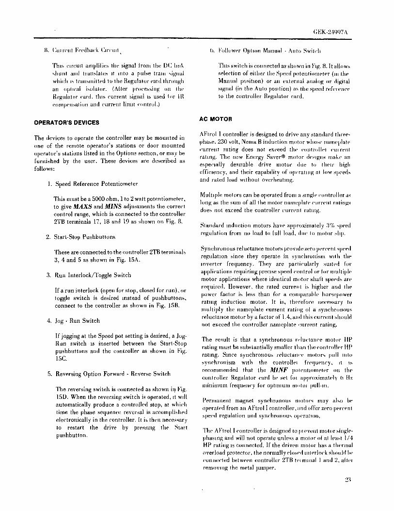
8. (:ul,'cnt Feedback (hrcmt t). Folh_wer Optmn Manual - Auto Swilch
Tins cmmlt ami;lilies the signal trom the DC hnk This switch is connected as shown irt F,g. 8. It allows',htll, I al,d tlanslates , (tiro a pulse tram qgnal selection of either the Speed potentiometer ('l' Iht,
which ,s transmitted lo the. Regulator card thr(mgh Manual posihon) or an external analog m' digitalat! .pfwal isolator. (Alter processing on Itl{' signal (in the Auto pos,tion) as the speed referenceRegulator card, this current signal is used t,)r JR to the controller Regulator card.con, l)(,nsalion and current linul ('(mtrol.)
OPERATOR'S DEVICES AC MOTOR
AFtrol I controller is designed to drive any standard three*The devices to operate the controller may be mounted in phase, 230 volt, Nema B induction motor whose nameplateone of the remote operator's stations or door mountedoperator's stations listed in the Options sectmn, or may be current rating does not exceed thc contr,)lle! cu, remrating. The new Energy Saver® motor designs make anfurnished by the user. These devices are described as especially desirable drive motor due to thc,r highfollows: efficiency, and their capability of operating al Iow speeds
and rated load without overheating.1. Speed Reference Potentiometer
Muhq)le motors can be operated fl-on, a single controller ,isThis must be a 5000 ohm, 1to 2 watt potentiometer, hmg as the sum of all the motor namet)lah' current ratingsto give MAXS and MINS adjustments the correct does not exceed the controller current rating.control range, which is connected to the controller2TB terminals 17, 18 and 19 as shown on Fig. 8.
Standard reduction motors have approxinialely 3% ,q_e(;d
2. Start-Stop Pushbuttons regulation from ntt load to tull load, due lo motor ,.,lap.
These are connected to the controller 2TB terminals Synchronous reluctance motors prowdc zero percenl speed
3, 4 and 5 as shown in Fig. 15A. regulation since they operate in synchronism w,th thereverter frequency. They are particularly sm(ed for
3. Run Interlock/Toggle Switch applications requiring precise speed cml(roi or tm' muhiph'motor applications where identical re.for shaft speeds are
If a run interlock (open forstop, closed forrun),or required. However, the rated current is higher ami thetoggle switch is desired instead of pushbuttons, power factor is less than for a comparaldc horsepowerconnect to the controller as shown in Fig. 15B. rating induction motor. It is, therefore necessary to
muhiply the nameplate current rating of a synchr(mous
4. Jog - Run Switch reluctance motor by a facto,' of 1.4, and this currmtt shouldnot exceed the controller nameplate em'rent rating.
If jogging at the Speed pot setting is desired, a Jog- The result is that a synchronous reluctance motor tipRun switch is inserted between the Start-Stop rating must be substantially smaller than theeontroih'r ItPpushbuttons and the controller as shown in Fig. rating. Since synchronous reluctan,'e motor,, pull ,nto15C. ..,ynchronism w3th the controllel frequency, it I.'-,
recommended that the MINF polenttometcr on the5. Reversing Option Forward - Reverse Switch
controller Regulator card tit. set i'oi approximately 0 rtzmininnJm frequency for optmnml nil)lO, pull-re.
The reversing switch is connected as shown it_ Fig.
15D. When the reversing switch is operated, it w,ll F'ernianent magnet synchronous tnoh)r,q may also beautomatically produce a controlled stop, at which operated from alt AFtrol Ieontrollcr, and offer zero percenttime the phase sequence reversal is accomplished speed regulation and synchronous Ol,er:,mn.electronically in the controller. It is then necessary
lo restart the drive by pressmg the Start The AFtrol ! controller is designed Itl ptevellt motm'single-pushbutton, phasing and will not operate unless a motor o! at least 1/4
HP rating Is connected. If the driven motor has a thermaloverload protector, the normally closed interlock shouht bcconnected between controller 2TI! lc, minal I and 2, alttq
removing the metal jumper.
23

(; EK-2;9_17A
· 1 1 lr,_ lu_r r Jk rl,w _
DERATING DATA
",laudard a.(_.mol,,rs mu,,t be derated it rated load i',appliedowq' a wide ,,in.cd range lo prevent overheating at Iow_ppeds W)li"l'p Iht meier cooling fan is not very effeettve.Der;tling i', u',uall v not necessary for fan or pump type load,,where h,ad torqm; dc-crea,es with decreasing speed. The[ugh ellMeney Energy Saver®motors normally do not
have to be derah.d for any type of load becau.,,e of theirlower losses.
a,(; motors may al,o need lo he dcrated tm high ambient orhigh ahitudc e.nditlonS. Refe,r t. General Elet'trieApphcatmn Mqnual, (;ET-6659 or contact your nearest(;eneral Eleemc (:ompany representative for motor,terating recommendations.
POWER FACTOR IMPROVEMENT
Small dr,yes .,uch as AFlrol I will seldom create concern
,,_cr power ta,'tm'; however, constant torque loads drawapprox,mately constant KVA from thc line over the speedrange, .,o as lmwer factor decreases at low speeds, therequtred rcacttw, power increases. No stogie value ofcapacitance (';.I.I1 I*e correct over the entire speed range, so[lower facl(H' lml,rovem_:';lt should not be attempted on adr,ve-bv-driw, b._,q,4. Instead, the ,,ubject should bealq)l(m('he(t ()ti a plant or alea basis. See apphcatmn datac(mlaine(t in (;!']T-6650 .r (;ET-(>468A
2'1'

) (;Ek 2 1'_)7 \
I . I ii_ll ii i
(CONTROLLER 2TB) START - STOP
PUSHBUTTON A
C_)_) (*)I) S,TIART(S) I CONTROLST0_ 0
(CONTROLLER ZTB) RUN INTERLOCK
CONTROL B
(3) I RUN (4)[ (S) I (CLOSE TO RUN)II
(CONTROLLER 2TB) START -STOP
(3) (430 tS) PUSHBUTTO N
WITH C
RUN_ JO6
O RUN/JOGSTART SELECTOR SWITCH
STOP IQ.z..G .,, O C
(CONTROLLER 2TB) START -STOP
(3)I .......FWD (4) (S)')(6)I'iO_--_R'EV_'--_)r PUSHBUTTONwiTH
D
REV WD REVERSING
START SELECTOR SWITCHI STOP t_D..L_ .. 0 0
FIGURE 15Operator's Start-Stop Control Options
23

I,l,.h'2l,qO7A
SECTION 3.0 CAUTION
RECEIVING, HANDLING AND STORAGE I)l,,'_()'l'l';'_()I'ER^TIN(;' I'll()(:l,;I)lllll,:$,iNI)I'Ii_(:TI(iESTIIAT, Il.'NOT STRI(:TI,YOItSI,:RVH).
RECEIVING M.iY IIESIII/I' IN i)AMA(;E TI) OR I)ESTRU(:TIIIN (IFTill", EQIIII'MI,]NT.
Th,'eququm'nl..houhtbe placedunder adequale(ow'r
immcdi;,hq,, up.I) _ecmpI. Pm'king casesale not _Lulal)le i,()I,()R -- IIl,A(:k LI",TTEIIIN(; ()N ,'iMBEt{ 1"11':I,i')h)l.uld.ororUUlu'ole('lcd,.,lorage, Eachshq,me.t,,hould
bc.';uclullvexaminedUl,.Uazrlvaland checkedwiththe NOTE
p;,{krugh,.,l.An_ ._hortageordamagesh.uldbereporled
i.l()tnplly I. thc varrler. It require, d, a,,si,.,tan(e may be I)ENIITES AN OI:'ERATING PI'IOCED[IRE (IRol)lalned trom Ihe (;eneral Eleetric Company, Speed I',ONI)ITI,ON WItlCH SHOULD BE tti'CHH, GHTED.Valiahu' I'rodu,'t'., Operation, Erie, PA. When seekinga,,,.,I,,hmce, plea,,,c use Iht drive serial uumber to idenld'y (;()1,()11 -- BI,A(:K I,ETTERIN(; (IN WItlTE FIEI,I).thc eqmpmenl. Teh'phoue: 814-,t-55-0521.
INSTALLATION AND OPERATING LABELSHANDLING
WARNING_A'allmmmled ('.ufr. lh.r,_('all I)elra.,_llorh'd by hfl IrLwk_v,,dh lhe I',rk,, C.ml)h'h'lx under the ba,,e, (.are being takeu IMI_RI)PElt I,IFTIN(; i'RA(:TII:I',S IiAN (;AIISEdl,,r thec,.rr.lhq &,._.ot rip. SERI()IIS (IR FATAl, INJ[IRY. IJFT ONI,Y WITI'I
il)EQ[IATE EQI. TIPMENT AND TI'/AINEi)STORAGE I'EI_ISI)NNI']1.
II Itl(' equqmlc. I Is ._;1 lo };¢' .l_lalled .nme41alely. Il WARNING: HIGH VOLTAGE,%hllll]({ Ill' St()l('(t Ill a ('lean, dry I()('all()ll ,ti dlll[lllqlI
h,ml,e.,,alulc.,, Irom -21)°I' (,4°Fl to 55°(] (13I°F). The EI,EI;TIIIC Sti'til;K I:AN I;AI,ISE P!FRS()NAI, INJliR'I,;ur_.umlmg au mu,,| he flee ot (hemwal and e,le,'tru'allv ()R I,IISS OF I,IFE. WHETttER THE AC VOI/I'ACE_,n,h.,,'llw' ,f.,'_-i roslve c..ulammauls ql rpI:'I,Y iN (;ROI IN1)ED OR NC)T, ttl(;ll VOI/I'4CE TI)
(;I/()I. TNI) WIIA, BE t:'t'IESENT AT MANY F'OINTS
}_'_f,.auli,u,., ,,}l,.uhl he hlkcn Io [uow'uI _ondru,.,alion [rom iVIIEN IN'";TRIIMENTS SIICtt AS OS(,qlJ,()SC()I:'EShu Imng wllhtu Ihe ,rqu]pmenl enclo,-,ure. It' ,I.rage iRE [ISEI) TI) WORK ()N I,IVE EQI]II:'MI':NT, (;I'IEATru_uouu]('utcx(,'ell_a 15°(:(27°l")dr.l)ulh'ull)('l.Hu['('al ('illTl()N MIIST lie liSl':l) WIiEN ()NE I)l" Till':._()i)er_ertl lei:tilde hum,,hlv, over a,l,-houl I.'[l-(I.a .-ul,',' INSTlilIMI':NT I,EAIiS IS (X)N NEIYI'I_:I)TI) Till'; I' iSE.I heal dmuht l,c m,uh' a_,ul,d_lem the uear va.'uulv .I Iht (Ill ()Tlll',l/ ME'I'M, PAI/TS (IF TIlE INSTI/IIMI':NT,
c,mllolh'l illghel huuluhlu,, wllh _malh'r lcml)('rallllc Tills I.I':AI) SII()[II,[) NIIT Ill': I:IINNEI:'['I':I)'1'() iN.'h,mgc- _lll 'Il.,, cau.c c.mh'us,Hmll I NI,III)IIN1)I':I) PART (iF TIlE SYSTEM IINI,ESS Till';
INS'I'III_MENT IS INSIII,,iTEI) I:I/()M (;I/(IIINI) ANI)SAFETY FOR PERSONNELAND EQUIPMENT I I'S MI,?I',\I, I',iRTS TIIE,iTH) Ah I,IVE EQI III'MI,;NI'
TYPES OF LABELS I ,'-,I,;Ill: iN iNS'I'I/IBMI,.NT IIAVINI; IlI)'l'll I,E,il)$I'.;,()1,iTEl) FI;I()M TttE (;ASE I'EI{MIT (;R/)l iNI)I N(; I)l,'
WARNING Till.; (;_Sl.:, I,:VEN ix, ItEN MEASIIREMENTS MIIST lieM it)E t',I,:T\%'EEN I.IVE PARTS.
I)I,,N()TI.:S t)I'I,:I/,iTIN(; I'I/()(:I,:I)III/E._ iNl)I'I/i¢:TIi:E_ TlliT M,iY I/I,;SI,II.T IN I.'EI/SONil, WARNINGIN.ii[I'IY ()1-I I,I)SS ()1" IAI:l,: IF N()T (:()lll;llg:'l'l '[I,'()l.l,()iX ElL I)() Xl)'l' ,SEll\ 1(:1,:Till,: I.:QIIII'MI,;NT l\ lIEN PI)iX,I:1_
I_ il'l'l.lH).( I)l (ill II1.\( k ()R '_%IIITE I,ETTI,3/iN(, ()% i I/l,.I) NOTEI:IEIJL
il,i\ \'_.'-:, HE,il) Till:, (:()MPIJ_:TE INSTt-II,(:TIIINS1'1'11()1-1TI) ,iF'l'l.¥ IN(; I'()WEI-I ()R TR(I[IIIIJ,:SI,I()I)T-IN(; l'lll,, I_:QIIIPMENT. F(II.I.()W TIlE $'l'&ll'l'--llPI'RI)('I,:I)I I/ES STEP I/'_ STEI'. REAl),\Nil I11%;1),ii.I.V_/RNINi;. (:AIri'iIIN /',,NI) N()TE IAt-IEI.S I'IIS'I'EI)
2h () NTtl, E EQ[I1p MENT.
(;EK-24997A, i ! i i., i
SECTION 4.0 MOUNTING
rca.i.ial)ly II,d, Viq'[li',l[ _ill [iii'<' [el)iii' Ill(ll. Jlll]ll_ It.d....ir(,
Thc Al"ll'()l I c()nlriiJh,r l. _ullai)le f(n hi(iq la( hlly ari.d_ [(,c,tlc(I _l, Ih(. l.p and })(HI(mi ('xli'rtm' Ila.gi._ .ilh.'hcd t.whcrc illller induql iai rqtJml)m('HIELmshtlh'it. Il q.,.l(I il(, Ih(' ri'a( i)am'l i.t Iii<' (qt('l(),llr(', _(,i' ()illhllt' (h_iwlllg_ I"lg_]n,,tallcil in wi,ll-vcnl]lalcd al i,a?, wllh ,imb,'nl Ih aim 17for li<<lllllllllg <hlllt'lisl()ll", ,tttd <qlultr-,tttl' wclgltt-,
h'n]l)Cl,lltires ra.glng Il-m 0°C (32° I") li) 1.()°11(I() 1.° I"),m(I I ('lal I v(' h ui'nlillll('_ Iq)h)()()( ( II sh()uJitI)c icc()gm]z(,(I; CONNECTIONSh.w('vcr, thai SlnC(' llic i'xlwihm('¥ iii ..l ch,clii)lni'('(llii[Hill¢ll[ dt'('l't¢[t%("4 v41llt IIH'l<'LF-,('i{ [ttlllll('iT[ |t'llll)<'l',tl(ll(' , \11 Illl('llldl {'()llll('('llOI]% l)('lw('('ll ('()lII})()ll('lll'-,, ._ili(] _illJ-
Iii(' i('ihl('llon oJ lhe an]J)l(.nl h'lll})('raltlr(' will I)ling ,lhi)nl ,i.,,('ml)h<',,,in itl(' Al"lr()] J ('()nll(lll(,I .ii(' ma(h, al (;cn('i,ll('xh'l]il('il ('()nll_(ll](qll llic I"i)l (,x,lnlp]<,,]()ngi'r ('Omll(incnl E]('('ll lc (:im]liarlv i)l)tli.l.d aihhli)n_ il(dYl)c td, li)r '_(,I I.'hlhh' ,,h(luht b(' CXl)C('h'dd' Ill(' ambl('nl tcnq)('ratl.(' r, hchl In,%lalh,d al Ibc I)urcha,,cl ',, .I)litm.
])i'lw('('ll 200(: (()_'_°I") ,Hltl ;'_0°( ' (87°1'')CAUTION
Ih(il,(', i)('rfi)rmal]c(' a,d i]()rnlal (ll)('lall(mal Illc i'.l. Ii('CXl))','h'dl)y mallmnnmg a i.,)laU' ('n_il.mui,.I i-I iii<, BE StIRI", T() PR()TE(?I' Till'; IN'H",RN,\I, I'I(INTEI)d[]vc s_.d('.n. (;IR(:IIIT (;AHI)ANI} ()TIIEI{ (;()MI)()NI':N'I'$ I"1_()\1
METAl, I*AII'I'I(;I.I';S WIIEN (;IITTIN(; ()1{ I)RII,I,IN(;I';nwl<mnlenls whi('h lilt'hide ('x('i's_lVealli()tllll_ ()1()Il(' (ir ENTI{AN¢;ES I"()R INTM{¢;()NNI';I:I'II)N _\ Il{IN(' \NI)
ln(_r('<ifItt<' following <'ltara('tert.,.li('.,-,sh(luht h(, ('.,,,,..h.red (:ABI.ES}iii. Id(. h) ih'lye })('r[olman('(. ,I,l({ III(':
IT IS I{I';(:()MM ENI)I';D TIIAT & (;lCM';NI.M", I'tlN(:II BI';I. lin'l, du_t and I(llelgn nldll('r, I,ISE!) I"()R (;tlT'I'IN(; (;ABI,E ()I)ENIN(;S IN TIlE'2 ViI)rali(m a.d ,h()ck. EN(;I,()S[IRE.,'_. MOl_|tll(' and ('<HTO_IV(' vapors.I.. Temperature ('x('tll'hl()ll_oul.,,ide _pe('lf'i<'(Ilmm,, WARNING5 (;au,',hc fumes.
6. Power lin(' flu<'tuati<)ns. &LL MOTOR BASES AND (;ONTI'/()I.I.EI/ ENt',I,I)SI'RI';
7. I';Icch-omagneli(' inlerferen('e (eh'('trwal rli)l_e). HOUSIN(;S SttOI1LD BE (;()NNE(:TEI) T() Till':INSTAI,I.ATION EARTI! (;I'/()IINI)INC $5N'I'I';M iN
Thc t(l|ally euclo_ed (NEMA t2) pm'lion <it'thc ('(lldlidh'l EXTI';RNAI. COPPER (.;()NNI';('.TOI_ IS I.i)(',VI'I';II ,VI'-h(,uht lic l)()sm()ned Ii) p('Enlil h('l.ll I,:t<halloll t'l()lll all Till'; !:f()TT(IM I.H"TSII)I';()FTIII';(;(INTI{(II,I,M{ iNI).ut I,(cc.. Th(' NEMA I v(,nlll,Hi'it i)arl of Ih(' wall mi)u]lh'd IS SI)I'I'AilI,I';I"()I_ (:()NNE(:TIN(; i(;I{()llNI) ii IRI';II_i'i).h,lh'l ,nay b(' i)lac('il ni'xl ti)anolll('l ('llvl().urc i)Ei)_.h,(I MEANS ()l" ,i (;()PI)EI_ I,tIC (SEE I"1(;. I()).,t ('h',.al]('c l_<'lw('('nIh('m I_ lll,tllllallli,(] i'(lual I. Ih(' _.llhof Iii(. ('(mlrolh'_. Clearan('(' _tl lc,iq ('<lual I() Ibc wl(llh .I NOTEIhi'n cn,'l(,,ul(, ,h()uhl al,i) I)cav.,hd)l(. _nIr()m ,() Ih,il Ih('
,h.)l i.av fully .pen ii.' <'a.y acc('_. (_<.cI:% 1(_). IT IS I/I';(',{)MMI';NI)!"I) TII VI' TIlE ('.()N'l'lt(}l,(:()MM(IN (:IR(:IIIT lie (;R(IIINI)I';I) ..iT ()NIA ()NI':
WARNING I)()INT WIII(:II IS( 2'1'11-22). I1" Till'; ,";I)l'.l';llI/I':I:EIIEN(:I': IS SIII)PI.II':I) I1'_ & I'R()(:I';._S
I.:XI)I,(;)SI(IN (IR I.'IRI,;S M,\Y I{I,;SI_I,'I' I"I{(tM INS'I'I/I_MI,;N'I', 'I'IIElil,; Sill)Ill.I) I',1,,Nil ,M()I/I,:TII_Nil(Il NTIN(; Till.; (;()NTII()I,I,I,;I/ IN II\ZiRI)()I _ 1,5 V()I,TS ltl,;TWEI,;N ITS Sl(;N,il. ()1"1'1'1T \_.1)
\REIS Sl_(:ll 'iS I,()(:i'l'lllN_ WIIMIE INI.'I,iM (Ill I.; (;I{OIINI).(SEE H(;. 18)()1/ (:()MIH;._TIP, I.I,; \ il'()l/._ ()Il Dt'hTS iRE
I)ItI';_I';NT. AI,'Tt{()I. I (:()NTII()I.I,I,;R_ MI q'l' lie CAUTIONIN_'I'\I.I,M) iV_ \_ FR()M II \ZiHI)()I,S il{I,;iS Ei I';\
I1' I hl.'l) \VITII '\(: M()'I'()I{S SIII'I'ilH,E I.'()1{I=Sl.; IN (;AI{E SIt()I]I,I) BE TiKENT() SEI.; TII \T il.l._1(11 I()(;VI'I()\.", INTI,:I{(;()NNI,;I:'I'I()N \VII'lIN(' IS ,_I?,EI} iNI)
INST\I,I,H) IN ,i(:(;()RI)&N('.E \'t I'111 Till', I,VH,,,'.,TM)I'H()N ()1,' TIlE N,iTI()N\I, I",l,l,,(;Tlll('\l, (:()I)E
· (NE(;) ()1{Till.; (;_N.\I)IAN M,I.;( ',TI{I( '.\1, ('.()1)1';(('.1',(.)iNI) I_,E _;i)NSI._'I'I,:N'I' _\ ITII il.I. |)Flll. l_&PI'I.I(; \III.E I.( I1' \[. I;I II)1.;_

m
NOTE
II I Ill', _.¢)NI'I_¢)I,I.EI{ I'.,\NN_)T BE S'I'¢)t_I'EI) B'_ Till.,N_)IIM\I. STI)I' I.'I}Ni:TI()NS (S'I'()P I*IISiiIIItTT¢)N.ZI_.II() _i'I,.EI) SI.;T'I'IN(;, ET(;) I(EMOVI,; t'{)WEI{I*I(( )_,1Till.; (;()N'I'H( )i,I,EH.
WARNING
Till,. N¢)I_M \1. S'I'()I' I,'IIN(/I'I()NS ()F Till.:_'()N'I'II()I.I.I..I{ (S'I'()I' I)[]SIIBIITTON. ZER() Si_I,;EI)_I..'I'TIN(;. 1,71'(') _1_1.:N()T IN'rENI)I,;I) T() BE IJSEI) .4._\ I'()\LI,;I_ I)IS(:()NNE¢:T 1,'()1_Till,: (:()NTHO!.I.EI_()[ TI'()i '1'

I_-AVAILABLE
AR
EA
FO
R/
CO
ND
UIT
EN
TR
YC
LEA
RA
NC
ER
EQ
'D7
_6.
00
//_._
_-'_
;---
jl_1
L/
irM
AX
PR
Od.
OF
OP
TIO
NA
L,-
--..-
-_,._
ITB
+'I,_
1.4s\
DEVICES
ON
DOOR
-,.,,m-Nm
o_z-_m
\--
,o.oo
j.TG'OL?o2 O,t2
2TB
15.06
TO
PFLANGE
'
Nn._
400
'"*{'i_
-15
0006
-_--
_'_
0'L_
/I
+
,I
.2.
00V
IEW
AT
"A"
OF
CU
ST
OM
ER
CO
NN
EC
TIO
NS
_e_
-II
/_-.
.I
26W
ITH
DO
OR
OP
EN
FO
R3¢
,2
TH
RU
7.5
HP
'I
X--
--/
XI
/_'-.
.'"'_
WE
IGH
T:
75'
FO
RZ
&.3
HP
WE
IGH
T=
95_'
FO
R5
&7.
5H
P
_IT
B
21.2
619.5
02T
B
[LE
SS
-,._m,r_n_r-.m_o=__m_________°_
+F
ANK
IT)
F]G
.I-"
JV
IEW
AT
"A"O
FC
US
TO
ME
RCO
NN
EC
TIO
NS
WIT
HD
OO
RO
PE
NF
OR
I_,
IT
HR
U3
HP
WE
IGH
T=
70#
FO
R1-
1.5H
PII
__\
\C
AP
TIV
AT
ED
WE
IGH
T=80'
FO
R2-3
HP
LAT
CH
]N
O1.
00
i,//_
IC
ON
N-
HA
RD
WA
RE
I'
f
.0
/._
j=:_==_
-/_]
ISE
E'
_.31
2D
IA12
,--
__m
.,,--
.34
_GR
OU
ND
NO
TE
#'3--_-0_
IdTG
HOLES
(FOR[
/SEE
bl]N
I/4-
20H
DW
)'_
C15
.68
-IN
OT
E#I
JLO
NB
OT
TO
MF
LA
NG
EF
RO
NT
SE
CT
[ON
D]R
EC
TIO
NO
FA
IRN
OT
E#I
-(N
EM
A12
]F
OR
FA
NF
AN
KIT
US
ED
DR
IVE
AS
MC
AN
BE
SE
TO
NB
AC
KS
UR
FA
CE
_PR
OV
IDE
FO
RW
ITH
7.5
HP
ON
LY.
OR
UP
RIG
HT
ON
ED
GE
SA
SS
HO
WN
.A
IRC
LE
AR
AN
CE
CA
UT
ION
MU
ST
BE
US
ED
WH
EN
DR
IVE
AS
MIS
SE
TO
NE
DG
ES
TO
PR
EV
EN
TT
OP
PLIN
G.
O.
FIG
UR
E16
Out
line
Dra
win
gA
Ftr
olI
wal
lm
ount
ed_o
['.2
'-4
(3
6B
60
54
05
EB
)>

t-5 4-- .-.4
MA
XP
RO
JOFD
EV
[CE
S--
7F
RO
MR
EG
UL
AT
OR
CA
RD
/1.
00-'_
,'1"'"
--r-
:312
D]A
/
75
_!=
13s
o=
1_
[r1
.50
-4bS
7S
-_·
I(I
'.
_I
L.62
5D
TA
_--
Ur_
'_r-
--"-
-_lT
DU
--
IllA
IRO
UT
'bi
TE
HO
LES
ON
,"'--
'6.
00q
+m
u_r
e:e:
E+
.4.5
:'
JT
OP
FLA
NG
EJ-
I.....
m....
:;
II
ITB
k/
'"'"-
-'"'
_I
2ID
,j/j..
...I_
$EE
FIG
S4
&2:
_[
x_¢"
-_1
'f"
r?
'r-IC
US
TO
ME
RC
ON
NE
CT
ION
SF
OR
3¢',
ZT
HR
U7.
bH
P)
A]R
,W
EIG
HT
:60
#F
OR
Z&
3H
Pr_
,,_-
L__
e_J
AIR
\13
0"I
_t_J
WE
IGH
T:
80#
FO
R5
&7.
5H
P'_
'O
UT\
SW
ING
II/
20.3
Z,
:'x
_'l
::'.
1900
INC
OM
ING
PO
WE
R_
[__
/ti/O
UT
OO
,NG
PO
WE
R(_
1713
d-z
z_
--'.
is.o
o--
[-F
(LE
SS
em
"C
AR
DIN
_l_m
,_
'=
]%
'_P
O'S
ITIO
N/'
:;:
:2_
¢C!
_'":
::_
''I1
I,,
n-
_'n
!_
:[I
'I
't
[+
I'.O
0IL
.--
_J
7J__
_}'_
NO
TE
"I+
t
_/fi
tG
RO
UN
DC
ON
N'E
E'IT
lIC
US
TO
ME
RC
ON
NE
CT
ION
SF
OR
,¢,
,&
3H
P,
NE
MW
EIG
HT
:55
#F
OR
I-I
4/2
I-'P
DiA
WE
IGH
T:
65#
FO
RZ
-3H
P12
1M
TG
HO
LES
DIR
EC
TIO
NO
FA
iRtF
OR
I/4-
20H
DW
)F
OR
FA
N.
FA
NK
ITU
SE
DO
NB
OT
TO
MF
LA
NG
EW
ITH
7.5
HP
ON
LY
.a
NO
TE
#I-
DR
IVE
AS
MC
AN
BE
SE
TO
NE
_A
CK
SU
RF
AC
EO
RU
PR
IGH
TO
NE
DG
ES
AS
SH
OW
N.
CA
UT
ION
MU
ST
BE
US
ED
WH
EN
DR
IVE
AS
M
ISS
ET
ON
ED
GE
STO
PR
EV
EN
TTO
PP
LIN
G.
PROV[DE
FOR
AIR
CLEARANCE
I I
FIG
UR
E17
Out
hne
J)ra
wm
g,A
Ftr
olI
chas
sis
mou
nted
(36B
5064
05E
A)

GEK-24997A
POWER WIRING
Single phase, 230 VAC input is required for the 1 thru 3 HPsingle phase input AFtrol I contollers and three phase 230VAC input is required for the 2 thru 7 1/2 HP three phaseinput AFtrol I controllers.
A power input &sconnect mounted a reasonably shortdistance from the controller is required. A suitabled_sconnect sw_tch k_t for mounting on the controller frontdoor (by factory or the purchased) is available as anoptional modification. A hne d_sconnect sw_tch _s arequirement of NEC or CEC and all codes.
Power wiring must be selected according to all applicable!: codes. The maximum contoller input currents are listed
below. Power wiring should be sized to handle 150 percent
_!_:. of the amounts hsted.'_:-p
No of Input Max. Input Amps_: HP Phases (RMS)
1 1 71-1/2 1 102 1 143 1 20
FIGURE 18 2 3 8AFtrol I controller, door open showing 3 3 11close up to 2TB terminal boardpoint 22 5 3 17
and ground connechon 7 1/2 3 22
CAUTION
The motor power leads should be sized in accordance withMEGGERING CAN DAMAGE ELECTRONIC the motor nameplate currentratmgs. Wire slze should beCOMPONETS. DO NOT MEGGER OR HI POT selectedmaccordancewithNECorCECandalllocalcodes.WITHOUT CONSUl,TING THE SPEED VARIATOR
PRODUCTS OPERATION, GENERAL ELECTRIC A thermal overload protective device should be used toCOMPANY. protectthe motorwindingsfromoverheatingandresuhmg
damage to the motor. These overloads (or motorCAUTION thermostats) should be selected based on the motor
nameplate data and must comply with the NEC or CE(] andDO NOT USE POWER FACTOR IMPROVEMENT all local codes. These overload devices are not provided;CAPACITORS WITH THIS EQUIPMENT WITHOUT however, they can be connected to 2TB terminal board,CONSULTING THE SPEED VARIATOR PRODUCTS pOllltN 1 and 2 after removing the metal jumper that isOPERATION, GENERAL ELECTRIC COMPANY. normally ,,hipped with the controller.DAMAGE MAY RESULT FROM HIGH VOLTAGESGENERATED WHEN CAPACITORS ARE SWITCHED.
THE THREE (3) MAJOR COMPONENTS: (1) THECONTROLLER, (2) THE OPERATOR'S STATION (IFREMOTE MOUNTED) AND (3) THE MOTOR SklOULDBE CONNECTEI) IN ACCORDANCE WITH THE
SYSTEMS DIAGRAM, 36D87008AB (SEE FIG. 8).
31
GE K-24q07 A
CONTROL WIRINQ
Ttw control slgn,d interconnecting wire must be twisted,Iw-c,mhn.h.-m lhree conductor wn e having at least twotw,q_, pc,' tach. I'lns s_gnal wire muq Ire ,'un ,n separatemagm,tw comJud from power wm's to eliminate thepos,,ibilily ol eh', trlcal nmse pick up The comhnt can liengnl steel or flex dde arnmured steel. The s,gnal wn'e shouldnol be routed through junctton or terminal boxes thaicontain non-,,ign,d wires. For signal wire diqances of lessthan 100 feel use a minumum of No. 22 AWG. Fordistances of mot,' lhan 100 feet and less than 500 feet use aminimum of N. 1.6AWG.
It' ,,hielded wire ts used for the twisted signal wire, eachshield should bc grounded at only one point, preferably atthe controller end.
Nearby relays, .,,qenoids or brake coils can produce erratwrhiw · behavior due to electrical noise transients. To
elemlnate thi_ i,ossibility, an RC suppressor should beadded acr.ss fin <'otis of lhese devices. A 220 ohm, 2 watt
respdor in seric-, wdh 0.5 mfd,600 volt capacitor can beused m 115 A(] and 230V AC circuits.
AC MOTORS
The A(: moh,r must be installed m accordance with ,
._eparale mslruclmns included with thc motor. (]are should
be taken t- a_,,_c that the motor Is properly ahgned withIbc drivt.n machine to mlmmize unecessary motor loadingdue to shafl ml,ahgnment.
OPERATOR'S STATION
The (iper,:.ilot's -lallorl ITll. i",t be nlounted HI d ltlcahou that is
cmrvienl to thc <)pcrator but not more than 500 feet awaylmm the e(mlrl,llel. As an optional modificahon, all fornlsot lhe operal(_r'_, qahon ('an be located on the front door oflhe conlroller, ,qther lactory mourltcd or field mounted bvJ'he ,tUll l'}rw.,er
32

(;l':k.2 It)q7 \ii
SECTION 5.0 II a ,.m-',landard voltage,md/.r Irequencv ,n.lm I.
u,4ed, reh,r to the Ba_e _'l*e(luenc'$ jumper ,.eh,cllon
INSPECTION, START UP AND ADJUSTMENT 'l'able A (page 35) arrd lilt' voh.'. I,e,' hcqlzinstructmn,, later m flus sectmn. These willhavc It)
Every AFtrol I controller has been tested and adjusled m Ire checked and readjn,,led since the cmllrolh,r ha_the factory and is ready to operate. However, before been factory teated wdh a standard 60 hertz mob,,
applying power and starting the motor, the following unless specially ordered.inspectmn steps should be taken to prevent damage to the
cqmpment and to ensure a successful start up. h is recommended that tile motor be dlst'tmne('ltq/
fronl the driven mac}nnery at Ihe (mt(al st,lrt-np lo
INSPECTION prevent pt_ssrble, damage it' nnsopcralion occur,',.
1. Inspect the controller for any shipping or Checkthalthenlotorshaftcan})elotaledandlslrceinstallation damage. Inspect for loose or broken from bimtmg
control cards or plug-in option cards. Check for
loose connecnons where the Regulator card NOTEconnects to 2TB terminal board and the w_res
connecting to both 2TB and ITB tcrm,nal boards THE AFTROL I CONTROI,I,ER WILL NOT OPI':I/ATEand to the fuse block. Ifa door mounted d]scon.lect UNI,ESS THE AC MOTOR IS I';I,I';t:TIII(',AI,I,Y
switch or operator's station is provided, check that C()NNI_;(:TEI). I)IS(:ONNNE(:TI()N ()1" ANY ONE
all of the wire connections are tight. Fmally, check MOTOR PItASE , WII,I, PRI)I)IIt:E & 1"41,1,'1'that all of the ribbon cable connections to the SHUTI)OWN.
control card assembly are tight. 4. Check for pre_ence or absence, ol Ihe folhm'mg
terminal board or card jumpers (Refer h) page 36 tor2. Inspect all of the external wiring to see if it is 50 Hz input jumpers.
properly installed and connected according to the
terminal board sucker instructions and the system (a) ITB terminals T and A should be jumpcred d' a&agram, Fig. 8 (36D870008AB). Make a point to molor ammeter is connected belween h, rminal
cheek of all inlerconnecting wiring })elween tile T3 and A, and tilt; At: moh, T3 h'ad Is conncch,dcontrolh, r and IlS opcrahn"s devwes, AC motor, A(: I. ITll lerminal T.supply disconnect switch, etc., with an ohmnu,h,I.
(:heck thc resi,,lanec h) ground t)t all lerminal board (b) 2'1'11It'. minals I and 2 sh.uhl he iumpercd unh',_sITB wrong connections with all ohnrnmter lo cheek a motor thermoswlh.h, Iherm,d uvct hn,.I .clay m'
that the power wiring is not grounded. Cheek that other normally dosed inh'lloc[ I', ('t)llllt'l'lt.d
2TB terminal 22 measures zero ohms 1oground, if acro'..;'-, these lerminals. II any ol Ihe,,c arcnot, check whether the controller enclosure i,, ('ennccled tile jumper .,,hocdd bc Icnmxcd, I)nlgrounded at the grounding terminal (orr the outside elwck Ihat lire external mh,rh)ck t,, clo_t,dof the bottom cover).
(c) Regulator card posts SPW should bejumpered to
3. Check that the proper rating of AC motor is SPX and SPYjumpered to SPZ if the ACinpulls
connected to the controller TI, T2 and T3 single-phase and not jnmpeled hu' three-pha,,eterminals. The motor nameplate current rating (or input controllers.sum of muhiple motor current ratings) shouht notexceed Iht; controller current rating. If the nnrtor Is
a ,,,ynchrocmn,, reiuclance motor (inslead ot an (d) Regulah)r card posts F(:I and 1"11'2 ,,t.,uhl
lnductnm molor), Ihe conlroller current rating normally bejuntpcred mn'nl,dly, Jml Il)i,, intnpm 'should be 1.4. limes tile molt).' cmrenl rating lo shouht be removed It' thc (WI:IlK I".llo_e,alh)w for higher peak and pull in cum. nfs. t)phon card is mounted on Ibc I/cgulahu card
The AC mohn voltage and frequency nameplah, (e) I{egulah)r card po,,,ls BI"I, BI"2 or 1'.l"3,houhl I.'
ralings mu,,,l al,,o agree wilh the conlrollel raling. If itnnl.'t ed according lo Tabh' ,,\, il Ifigher than hO
a standard 230/_I.60 voh, 60 herlz nmlor in u,,cd, ri hcrlz molor fi'equcncy p, dcsn od.,houht be cmmechut fro' 230 v.h Ol.'ralmn a,,
nht)wn c)tr Iht connccllon tliagTam (h)w v,hagc 5. list. a vollmeter Ill check Ihal Ihp A('.,,ulqdv vollagcc.lmechcm) usmdly I)r.vith'd mt Iht mol.r h', urinal tm lilt, im'.mil3g in 230 volln ,A.(' +10 pcrcenl 5[n)x t'OVl'l'. I)tq t't,nl.
33

(;EK-21()()7A
START-UP PROCEDURE thi_, ,,e('tmrl I.r adllL'dLnelLI l'e( omnlendal ..n.. al.i I.
iILL'I}ES(;RIPTIC)N, sectloLI 2 O, [ILr an explanalion
I Scl lilt .peralor',_ ,qleed pol('nt]onn'h'r Io zei'i) under I{E(;III,¥1'OI'{ card.
le.mllh,h.ly I'Ounler-chwkwl_.e) fl' the l"ollower
()l_ll(ill i_ Ill( lud('d, qel tile opelahlr's Manual/Auto 9. (]()nllect lhe inol(n' ,,hall to tile driven iLLaehi,ler;'
,.(.h'('h)r '.wd('h m lhe Manual posHon and repeat tile above start-up steps. The moti)reurrenl wlrll be dependent on the driven load, but
2 (:lo,q, ltl(. d,,4Cl)nlrwet _wlteh to supply 230 volts AC should not exceed the motor or elmtrldler
power ILlIhe ( OllllrLdler. Cheek h_r 230 w_lts al'ross nameplate ratlrng. If the eontroller eannot atari the
Ihe hi)ad ,.te of Iht' eontrcdler tuses. It ti{) voltage ix motor or if motor cqrrent Irsexcessive at Iow speeds,
}n'estqH, icier IL)thw Troubh-,hootlng seetlron part increase the COMP potent]ometer settling as
A-I "No i,(iwer to controller" explained tinder adjustmentsNOTE
3. Press the iq_erator's slart pushbutton, (or close the
RIIN swm'h) and observe the greerL RUN lighl on IF' TIlE C()NTROI,I,ER ItAS BEEN STORED FOR OVER
Ihe reglrlrlah)r ('ar(t. It should be bhnkllng at a 6 MONTflS, 'FILE FLECTRI)LYTIC FII,TERflequencv i)t'2 lid 3 herlz. If lhe light ix off, refer to (]:',PAL]iTl)RS SHOULD BI'; "FORMED" BEF()RE
the Trouhledmoting ,;ectmn, Part A-2 "Can apply OPERATIN(, THE CONTROLLER ABOVE ISOV AL;'lq}power tlL cmltrl)ller, but canlmt start." Tile MOTOR. FORMING tS A(X]OMPLISHEI) BY
()pI';I/ATI NG THE (]ONTROLLER AT 150V AL: OUTPI.T
,1. Sh,wlyln,'rea,,ed,,operator's,,peedpotentiometer. I"()R 5 MINlYFES ANI) THEN INCREASING TIlE
The RtiN hght ,.hlmld iLlerease ,tx bhnklrng ()[ITt'IIT TO 200 V()I/FS AL: AND OPERATIN(; F()R 5
Ireqlrlren('v and Ihe motor should begin Io rotate Il MI)RE MINII'I'ES AFTF, R Tills PROCEI)tliiE, 'HiEIhe Irnoll). rotat,m ,s ba(.kwalds and the Reversing (X)NTRO1,LER MAY BE OPERATE1)OVER ITS ENTIRE
()plt(m ]%riot tn()vlited, press Ihe operah)r's ST()P RAN(;E.
tmshlL;,thm to sic){:) liw m()lolr, l)ls('()nneel 4(:
p()wer, IL'verse the ('onneetlr(ms to any two m(}hn' ADJUSTMENTS _ REGULATOR CARD (Se*, Fig, IL))h,a(Is and reslarl the ('(mtroller.
11II ,,, deslre(l lo change tile Regulator card a(ljustme,lrl¢,
5. I'.[lt'l'k lilt' A(: motor current wnh a clam t) mi liLe hdl()wmg procedures are suggested. Rei(.r ID the;IIIIIILP|(q. It the nmtor shall e, (lis('(inmeeted fl(m) I)ES('.RIPTI()N, Seclior, 2.0 f()r informatlr(,n im
I[le ({rlV('ll Ill'Lehilrl('ry, Ihe etlrl'elll I'(',t(llllg sh.LIld adltlrstme. II r,tilgeS all({ o})erallollr.
l)c al)l),.×mlahqy I/3 of Ihe nmi(i, nameplat('(I,rl'('l]l lari]]g fin stan(lard mdu('li()lL molo, s. /I,IINS (Minimum Speed)
(i Sh)wlv inclea,,e lhe speed l)ol(q]liomeler up to lite Nil,really, ltl(, MINS polel]hl)meter is ,,et tully (:C_ an(t
ni,irx.ntmt ,,pee(l ,,etllng while ()bscrvlL]g nIOt()l must })e ill the fully C(',W }lliSlrllronfiD, prol_er adjt]stm(.id (){
( ill l('lll ;lrl(] llri()l()r ()pt'rdthol]. 'i'll(' mol(Il shouht fl'lilt Iho MINF, Mlllltlrlunl Fre(luen( y })olentiometel. If a }ligher
,,milL,tidy uq) h} ,Is raled ,4peed and the ('tlrrre[lt (}flhe Ihan/ero lninlnmm _,peed p; a requirement, tl shmuld be ,,el
ih,.,( (}rll]e('f(qt IlIOt(_r s}muht r('nLain fan'iy ('onslanl ailel the adjlrlrslment (d MINF.OVe, IlS (qillre '-,peed rarlrge. If' ti)(, llrlOlor d()e'., llOl
.per,lrh' i_r()l)e, ly, Ir'el'er to ILL(' Troubh,,4ho()tung ,_IINF (Minimum Frequency)%lq'hi)Il.
W Ill, lilt' Speed Ret'e,l'nCc potent](mleter set al z(.ro (flLllv
7. Ih'c.','. Ihe Ol)elalm-',4 STI)P ptl",h}mlloL]. The nllm,r (:1 :W) al'ltl both thc MINS _ind COMP [mlel'itlrolnehq'$ Oil
,,peed 'd.,uht (h.¢eh'rah' ,.irm.,Ihlv (lowl] ti) a d.w lhe ltegLLlah, card set fully (;{:W, shirt the c(mlrolh, r Thc
.i,eed ,L'. can l.' '.een by Ihe Illin hght bhmkmg I){;hnk v,dhlge (SMt'h_SMN) sholrlrhtbenoglealer Ihm,_8
Ist'.llrU'ncx. The RtlN hght sh.uht Iher] go Dill aml ;oil.,.. Nl_rlrnallv. the MINI'' potentiolneter .holrlrht be
ILL('mi)lo, sh(mht qop. ,,Iju.,h'(I I(/ oblall, al, ]llVelr'tel' ()UIpul h'eqL]el.'V (ddppr()xlm.d(qy 2 h, 3 hell/. The Illin hghl ',h(}uht bc
8 11 ,hi'let Pill adjlL",lmelllS _,t Ilrlrlllllllllltl ",[}(q'(t, },lilLk]llrg al this treqtltql( Vam] Il ,,h()uht l)e po,,,,it)h't(} cilc('k
Ill]lmlllm_ fre(lunm(v, n]axin_mlr, sl)e(-,I, v()h_ P,., llllllllllllrlll [nvell('l tleqlru'r,(", hV ob,..elrvlrlg Ih(. Illin hghl
hill/(il' hl]e,lrl llnLe ale deslr(.d, lhe_ ,il(mid })e Ill,Id(' t)lil]k.lg II e({lltq,( _. 1[ ,ir %Il( hit)HI}ti', rehl(qan('(, lllOl(H 1,4
alii' h"'.h'd wh]h' the nLOhn'shmFt,sstdl d,,.(.onlr]e(.h,I being t]'-.(',l, ii i,., ,e('Ol]ll,l('llded lhal MINF I,e ,.('1 h,' ,i 0
h'm,, il, h,a,t. Reter ti, the .41).11 STMENT pa, I ,,f' hcrlz n,[,,,nl,,,, tre,tuwl,( x
31

GEK-24997A..... _! =,=,, . I II[ i
MAtS _,laxlmum Speed -- BaseFrequency) 3. For singh_-phase, inpul ('ontr(,ller,,, ii may n.t bep,),,,,,,itde to obtain more than 210 to 22(1 voh,, at
With the Speed Reference potentiometer set at 100 percent rated load. It may be nece,,,.,,ary t(, .,,lightly redu('e the
(fully CW), adjust the MAXS potentiometer to obtain V/Hz setting or increase theMAXS p()te.llmnleter
rated motor nameplate speed and frequency (normally 6(1 _,ettu_g t(r (fi)tam rated motor spee(t al ti]Il hlad.hertz). If this requires a reference voltage of greater than
8.5 volts as measured at terminal board 2TB terminals 18- 4. If rated m()tor voltage tx less than 230 volt',, a(tlusl
22, install a jumper between Regulator Control card post,,, V/Hz to obtain rate(t motor vt)hag('.
BI"I all(] BF2 to increase the base frequen('y setting. Re-
adJuSt the MAXS potentiometer to rated m(,tor speed and LTIM (Linear Time Adjustment)l'requen('y. A},,o, readjust the minimum frequency tls .',el hy
the MINF potentromeh',r, sni(:e this will als() change It Adju,nt thc LTIM [)ol('llllolneter Io ()[)ttull ,tit a('('t'h'tatlott
higher than 60 hertz fre(lucn(.y ]._re(lulred, u.q,Tabh. A asa Il(ti(' h'(iBn z('ro to lla'_(' ,qlee(I equal lo Ill(' Ilnll' ite...(.,I ll)lgunh' in sele('t,ig tile proper })ase frequen('y juml)er. II i', Ill(, at)lih('ali(in. T(.n ,,('('(,n(ls i,, a g(iod avl.rag(, a('c(.Ic_all()l]
possdth, that thc next higher or lower bane [r('(lueil( 5 hit mauy industrial apph('ation,-,. The ({('('eh'ratl()u lira(,
jumper than the one indi('ated m Table A may be nece,,sarv fi (inl }ia.(' I() z('ro .,p(.ed ,dmuld 1)(,al)t,r()xlniah.lv Ill(' .amc
Icl en_,ure that the voltage between 2TB ternnnal,$ 18-22 I'., as Ihe a('ceh'ratloll lime, bul may h(. h,nger hil ta.,,I I, TIMbetween 5 and 8.Svolt,,, when the contl oller output ls at the ',ettmgs. Il ltl(' ('{mtr(dh,r trq),, (,ut thnnlg ;,'c(,h,lallml m
desm_d base trequeney. (h'('eleratlon, tly ,_etling the LTIM ])(ih'nf]()niel(,r [(il ,ih)nger Imle.
TABLE A
Base Frequency Jumpers (:()MI' (IR Compensation Adjustment)
Base Fre(lucn('y Base }"re(luen('y .lump('[ T}l(, anlounl st IR ('()nlli(,ll.,,at.in le(lu.r (,(t .. (l('p('nd('nl (in
Iht. anlounl (if nloh)[ t(ir(lu(, re(lulled h) stall Ill(' (liter. ti
machinery and lo run al h)w 'q)ec(I,.. '1'.(( hlth'
50 to 70 I'tz None ('()n]pensalion will not t)rodu('e ('hough re(il(ii I()](lU(. ami
60 to 85 Hz BI"I to BI"2 re,hull itl ext'e,,,,,ive nlotor ('utrent. T()o tnut'b cmni,t.l_,,,lllon
75 to 105 ttz i BI"2 to BI"3 ('an pr(l(lu('e ex('e,,,,ive moh)r ('()ggnlg ami ('xc(',_.,tx(. i((i100 to 130 Hz BFI t. BF3 It)a({ ('urrenl,
Set the Speed Adjust potentlomet('r t() si)elate Ill(' nliHi)r ill
Y/H_ (Volts per Hertz Adjustment) al)proximately 10 percent (if rated Sl,(,(,d with th(' m.t(,_
('onnec, te({ to it,, h)ad. _(tju.,,t th(, (,_()Mt) i)(llenll()nl(,h.i t()Set the Speed Adjust potentiometer at the maxmmm (fully (,blain the minmmm mot(,r cul rent al n(irnial J,)d(t Shlwlv
CW) to obtain rated motnr nameplate fre(luency (normally lurn tire Speed Adjust i)(,t(,nlJonl(.ler h'onl fl-, illnllllliliti I()
60 Hz) and speed. If the AC motor is disc(mnected from the it', maximunl selling while ob_,('rvlng m(,tor ('u(l(,nl Moh)r
drlverl machinery so that It is at no load, adjust tire V/Hz current si. mid not ex('eed tlr(' mot(ir (,r ('()l,llolh'r
potentlometel to obtain 210V AC a(u(,ss the motor nameplah' ('urrenl rating atany()p(_,ratl(]gp(mll. I{('a. Jju.,Iterminal,, or approximat('ly 90 percent of raled motor the V/ttz ,,(qtnlg as ('xphnm,(t un(tel t'/ilz an(I (','ch(,('k
voltage, it' diiferent than 230 volt.,,, moist ('lirreill ()V('l the nmi(ir spet'd range,
After the motor shaft has been connected to lt,_h,ad and l tie I'LIM (Current Limit Adjustment)
(;()MI) potent(omelet has heeu adjusted ('(n' Best low s})(,e({
()[)eral]on, return ltl(' Speed Adjust pot('ntionleh'r h) it-, 'Die C!,IM ('urrent lnnit t_()h.ntloinetc( h,I, Itt'eh s(q ,il Itl('
n(aximuln setli,g and reche('k the motto terminal vohag(', tat'tory h)liniit al ]5()p(q'('ent of('(,(Itroller nam('platc rah,ilBefore readjtlsling the V/Hz potent]ometer, mark the current. Turmng CLIM (_C\V will d('('rea,(' ('tlri'el]l h(((it.
original nethng },oint Slightly adjust J'/liz ill ellb('r (]llrr('iil limil ('an Ii(' ill('l('ane(J J)_, nl(ixi((g CLIM ill Iht,
(llre('lion lo try to a('hi('ve th(' following: ('](l('kwiq(' (Jire('tmn. IIn(Jcr (l()lmal ('ll('lnnM;lll('('$. Ih('rc
',houhl b(' no n(.(.(t to a(tju,.l Ill(' t;LIM i.)h'l(llonicl(.I.
I. Mlrlinltinl motor ('urrolit at the loade,I operatlrlg
('ondillOll. FOLLOWER CARD (optional)
2. Motor tet'minal voltage Il()greatel than 23OV A(' t(,r If Ihe ()VI"I Ik. I"olh)wel ('ar(l opt,in is lurnl.,,h('d, sl.h.( I-
3-pha.,.,eirlpUl ('ontrolh, r,_. I"nllow(.( ('ar,l Ill SE(71'I()N 9.0 f(ir ,,i)(.('itl( . Jtlslrti('ll()(i,, I)11
_. a(Jjti.,.,hn(,nl,-,and jumper ('();]n('('ll()n,,.
35

(,EK-2 t()qTA
T
ADJUSTMENT RECORDS
Il t'., ',uggc,'.,h'dIh.tI a I (,(.()rd .fall adju.I,r.'.t. h('rna(i,'wilIllilt' I'(lllllll_ll'l ()[)erdllll_ suc('essfully trader tH)Filial('(.mhlmn_. '['tll.., will I,,' t,.,,d'ul ii, th(' eve,hi Il be('.me,,,
II('('('n'-,iIrv t() Ii'()llble s_l()O( Itll' (of]troller al a lah'r d;lte,
50 HZ AC SUPPLY OPERATION
.SI,in&m] Al"t_d I ((mtr.]lers ar(' adjusted attd tested orr 60
IIz Ar' 'mi)ply I,(,wei. For operatton on 50 Itz AC _,upply
i_.wer ', thc hdh_whlg change should ire made before qtarI-
Ill).
1. Smgh'grhase Input conlrollers - l{emove the SPY to
Ni)Z jumper m_ the }'legulator card.
'2. ']'hr(,e-ldhise iht}ut c/mllollers -- Add a jumper
a_ ros,_ I{,'gulatm card }rests SPY and SPZ, and ('ut
(mi r(-,i,,hn' 230 adjaeenl 1o lmml SPY, as shown inltl(' sketch [)('low.
* lis(' Ihe si)arc jump('r ( onnected ar'r()ss f)osls I,MP
and I,M N, or s.hter a jr]roper wire a('rt)ss post,s SP'_amt SI'Z
THIS RESISTORC: _- 0
SP2 SPY
*Use /he spare jumper connected across posts LMP and
LMN, or solder a jumper wire across posts SPY and SPZ.
"_h

(;EK-2,1,997A
SECTION 6.0 WARNING: HIGH VOLTAGE
TROUBLESHOOTING PROCEDURES I.;I,E(;TIII(', SII()(;K (:AN CAIrSE I'I.',IIS()N41, IN.II:RY()R IX)SS 1)1" I,IFE. WIIIqTIII",R Till'; Al: V()I,T4(;I';
A sy,,h'mali(' appr(_ach Is lrt}u})h,,-,ht)ohng wdl Ii'duct' lhe SIIPPI,Y IS (;R()I1NI)EI) ()1t N()T, Ill';Il VI)I,T&(;I';T()lime reqmred to find the problem. Tins approach con,,ist.,, (;HOIIN!) WII,I, 151';PIII';SI';NT 4'1' MANY I)()IN'I'Sst tryingtoidentifythesymptomqoftheprohh;m, laknlga WItEN [NSTRIIMENTS SI (',!1 4S I)S(;II,I,(}S('.()!q.;S
numher of meter readings depending on these symphml,,, ARE IISEI) T() W()RK ()N I,IVE EQIIII'MENT, (;IIE\Tand localizing the pro})lem to some module or a pr.,h'd (:AIITION MllST BI': I/SEI). WIIEN ()NI': 1}1" Till':em'mt card as a result of these readings. INS'I'RIIMI'_NT I,EAI)S IS (_()NNI,;lYI'I.;I)'l'l)'l'lll'; ti \_1",
(Il/ l/TIlER METAl, PARTS OF TIlE INSTRI MENT,TEST EQUIPMENT REQUIRED Tills I,EAI) Silt)Ill,I) NOT lIE (:()NNElYI'I';I) TI) \N
IlN(;R()IINI)H) PART ()1"Till'; SYSTIqM I!NI,I",?,,_Till*,These trouhleshootmg noles are written ,,,ol}ml all read,ngs INSTRIJMENT IS INSIII,,VI'H) I"R()M (;II()IINI) \NI)
may be taken with any gm,d quality muh,mcler (ir ITS MIqTA!, PARTS TIIEATH) AS I,I\E I';()I:II'MI';NTvohohmmeter. Adlgdalmuhmleter, suchasal"lukcM()dcl IiSE ()F AN INSTRIJMENT IIAVIN(; II()TII I,E,\IIS8020A, having high input nnl_c,dance will prowde accurate IS()I,ATI,;I) I"I/()M TIIE(;4SI'; Iq'_RMIT(;II()IINI)IN(;I)I.'rca,lings will, minimum loading of the c]rcmt being toad. ,\ Till'; (:ABE. EVEN WHEN MI';ASIJREMI';NTb MI IST lIEclamp-on AC ammeter in aL_ouseful in reading controller MM/E BETWEEN I,IVI_;PAI/TSml}ul acid lulll)ul currents. Never use a megger 1o ,'he('k tmc,mlrol or power (:lrl:ull grounds m,,ide the .'ont.'oller, a,, WARNINGthp, may damage the eqmpment.
I)() N()T SEIIVI(;E TIlE EQIIII'MI,;NT WIIIqN I'1)\$1,;1tTESTING SAFETY PRECAUTIONS IS APPI,IEI)
I'}ecau._etroubleshooting involves taking readings of t)olh When testing m the power area, ti I,',tec(mm,'mh.d II.m .tcontrol and power circuit voltages, it i_ ti potentially ',atety',taudpointthattheequiTmu, uthctutncdofl,thet(,,,Ihazardous l)ro(:edure h)r lmth the })ersoil (ton]g thc ('(lull)merit ('()nn(.ctions1)('nm(h,,,m(I Ih(, l,)w('r alq)hcd Imlroubleshooting an(t for lhe e(lmpoment, lly ti,Ih)wing ih(,mc,asur(mlenl.andlh(,(,qultmu, nllh(,nluln(,(l()ll,%ntl,re('ommended saftey preeaulio,s arid ohs(,t wng g()(M prior h) dis('om]c('lmg Ill(' le",l eqmlmn.nltesting practices, these hazards can be reduced.
CAUTIONWhenever possible, disconnect AC supply power h'om thc,controller before inspecting the umt tit' faking WHEN TAKIN(; REAI)IN(;S WIt!I,ETIIE(i()NT()I,I,I';Ittroubleshooting readings. Where operating v{)ltag(',,mu',l IS ()Iq';IIATIN(;, TAKE (;ARE Nt)T TI) SIll)ItTbe read, proceed as d the circuit being _ead is at p)wer IIETWEEN (;IRCIIITS WITtt Till'; MI';'I'Ell I'II()I/ES.potential. Ahhough lhe control ,'ircmtry assoc,ated wdh IISI'; INSUI,ATIN(; SI,EI';VI';S III';'I'WI';I';N I)I{IN'I'I';I}the operator's control cs al ground pohmlial, most of Iht (]IR(]IIH' (]Alii) (;()NNI';CTIt)N I'()IN'I'$ \S \ MI';'[NScontrol circuitry and all of the power circuits are at p()w('l TI) I)IIEVENT SttORTI N(;t)otetmals.
NOTEWARNING
Al,WAYS REAII TIlE COMI'I,I,;TE 1NSTIII;(',TI()NSEI,Et;TIilC SHOCK (;AN CATISE PERSONAl, IN.IIIRY PRIOR TO Al'IH,YIN(; PI)WI,;II ()IF Tlll)IIIII,E-
(IR I,()SS OF I,IFE. WItETIIEI/ TIlE AC S[II'I'I,Y IS SIt()()TINC Till,; I,;QITII'MENT.(;I/t)IINllEI) 011 NOT, lilt;Il VI)I/I'AGI,;S TI) (;Rt)l INI)
W!I,I, BE I_RI,;SENT IN BOTH THE POWEI/ _NI) REAl) AND ttI';EI) AI,I, W,\RNIN(;, (:\I"!'I(}N \NI)
(;t)N'I'R()I, (;IR(_tlITS. AI;TER AC S[IPI'1,Y I'()WElt IS N()'I'E I,ABH,S I'()S'I'I.;I) tin TIlE I,;I,}1II'MENTI)IS( ',t)N NE(_'I'EII, WAIT AT I,EAST ONI,;MIN[ITl,; FI)IlTill'; I)C I,]NK (;AI)AC!'I'OI/T() I/IS(:ItAR(;E III,;F'()RI,;T()IIt:tlIN(; ,\NY I'_1-I'1' 1}1,' TIlE (;t)N'I'II()I.I.Ei/I',IRI:t',ITRY.
37

GEK-2 _qq74
r llr_ i T I
GENERAL TROUBLESHOOTING b) If incoming power ih correct, cheek the voltagesbetween terminals FU1-2, FU2-2 and F[13-2 al
(..,.l,olh.i pl.bh'tn, eau usually lie separated into tw. the bottom of the fuse block. If no vohage ts
gcn,.l ,il ,.'et,.: present, one or more fuses are blown. DisconnectAt: power from the controller and cheek the
\, I:..Ir.iM' '.hut. down il! c,nlllOl De ,,tatted fuses with an ohmmeter to dctermine whleh ones
need to be replaced. Replace any blown tuscsIL (]onllol[er opel;tie, unpropcrly, with ones of the same type and ampere rating.
Th,' hdl.wliig ll.mhh",ll..tilig tm/cs ar(' [,esented und('l e) Before applying AC [tower, check for shorted
I_D Cern'iai headings. The notes are [url[ler subd.vided components iii the, controller by going through
Jill:el [lOOble ,'",_','[llilt()tllq Iii s,tVe [lille iii Ihe the step A reading,, contained iii the Trouble
Ii.ulde4mol tag iu m.e.s. These lloles i'eter Io lhe Trouble Shooting (;hart (page 39). If faulty readings are
Slu,,,Img (][larl which gives normal readlngsof tesmtanee,, obtained, go to the l'owet Module Converterand roll,iCes al var:ua', leM points, and comnmnts ,m Section or DC Link Filter Troubleshooting for
i,.,..ddc I.'obh'n:s and recommended actmn. When itl(. further instructress.,..ur, e .f lilt, probh,ln is determlm',d, rcler lid furthcl
Jnqllu,'li-ll,. ua:et th..peeiflv head,ag, suvh as (]mllro} d) lfTrouble Shooting Chart s/epA readmgs are all
I',,:r,{ Tr. ubh'shooli.g, Power M,.lulc (:onverler i.: good, go through the step B readings. If faulty
{llX,l,llcl ._clhlDiI Tr.ulde,,huolil:g. m' ItC I,ulk Fiher readings are obtained, goto the Power ModuleIi.uld:.shi,oll,g. ,Stone tar:her thulgs Io,'hcck aremeh, h',t Inverter Seehon or to D(] Link Filter
ul,h'l Mi,,ccllamqm,. ']'lmdde,.h.:lfing Checks, begins:ag Troubleshooting for further instructions.
,,:: I.age P.)i
II ,i idull "4[IHhlowll ¢}('1 or,,. Ill(' hdlowiltg se:lueu: e should 2. (;ali apply power to controller, but cannot ,;tart.Itc tl,.,i.d hi reM,liB the :hive:
a) Set the operalm"s speed piDtentmmeter al z_ro,
l. \\ ,11t '..:"_,el,i] lnlllllle '-,JUl Itl(: drive I::tk cap;lc:lin Io press thc Stop pushbutton tip resel the fa.llll
dl.,chalge dow. 1o 15 rolls or behla ia. me,tSUl-d latch, and press file Start p,shbulton. It tho
tDclwecn liegulal.r card Ii'st t.lqs SIMP alld SMN) RIIN light on the Regulator card starts blinkingat a low frequency, proceed to step 3 (eon:roller
2, Pie,.., Ibc ,%lop i.US[lhUllon and Ihen pres,, the Sit. ill Call be started but shuts down when oparator%
pu._lillull.n, speed potenttometer is increased) or ti} _t_p .'3
(cannot control motor speed with ,,pee,d
3. It lilt' ltl: ll:lk _lilhlge does n,.l dl,,chalge beh.w I5 potentiometer) under part B (controller t>perateav.ll_., ill,.: ollm,i I Iht ,\(: .uppl; p.wcr ltd alhm improperly).cdp;lclhll dj-ch,liCe, re,lPPh' X(' Pow:'l and iepedl
-icp 2..dn:_c b) If the RUN light does not indicate, che,'k all the
control card power supply voltages hstcd itt step\. (::,l:It,dl, q .ti:il. ,h,wn or i,ulnol bc .darh.d (] of the Tl ouble Shooting (]hart (page 40J. tfa_ly
power supply readings are incorrecl,: he,ok tbr
I N,, l,(:wcr hl conllollel, open eonnecll,ns, deject:ye control ct. fl!s, tffla:led eon:roi Iransfurmer as reconlmalMed Ill
,l) ()ItCh Ill:' c.)nlr.lh,t d.,)l mid :'ll:':'k Ille _,ollagv. slep C Refer Io Sect.in 7.0 for RemovaJ/lhq_a:
l.'l wccn lei nasal'., Fl l1- 1, I"112- I ,u.l I"l [3- l ,il and Replacement instructions
Iht ll.p id lhe Iasc hhwk wllh ,m M' vollnlelt i.
Th,'..' v_dlage., .h.uht all :cad tf..t 218 lid 2.-,_ c) It Troubh' Shooling (',bart step (: remhngs a:e all
v,dl. (2AU ;,dl.. +It) -5'i) Il IlO v(dl,lge ,)1 Sdllsfa('tory, go I}lroug}l tile Mep D rea(bngs. ]J
II..I :'el I v:dlage Is olltauled, Ill(' smuce of ill:. faulty readings are obtained, go tit the (;_oltlro[
I_l:,l,h'lu l', i1.' uwomingtmwet 1. Ill:'l_mlrolh.i Card Troubleshooting (page 45) for J,arther
('.IH'4k Ih,il I[1(' \(] [)ow(.r ([l_,(olllll'('l sWllch 1:) instructions.
II.',,ml,cdlc: (v.IHIDcalh,I. n.,uulcd.pl.)u}... h,..',l I.'l,,ic IIl\e'.,llg.lllllg t1111hcr d) If Trouble Shooting (:hart step I) leadingsareall
satisfactory, go through the step E readings,
(page 41) and follow the appheable comments.
:½8

GEK-24997A
0
·' , _]]
:;:] ;;;: ....:
_a
FIGURE 19AFtrol I controller, front panel details
39

O_
o _-< -o Om _a_B m_m _ mc
2 2ooooo8 oooooo_"_ _ 2 '_oeooo ooo OMO °._,o7 _ _.7_7_ _.77=._ 7 _ 7z7 777 77=..
I I I I I I I I I I [ I I I I I I I I I I I I I I I I __°_an
n
oO0 . _ t-OO°00000
Z z ZZ_ZZZ ZZ_Z_Z z ZZZ z_zz ZZZ _IZ -o
I I Illlll Illlll I Ill Ill Ill Ill _=_-D.
=-_§ oooooo §§o=g_= =-= oo_ o_O_oo_
0g c
o oooooo _. ffi
o oo _i0.......... ooo = ..... o .... oo ,_= rmoooooo --- i
-_ 555555 '_-
0 O 0 _ 0 Z o O0
- _ o._0 o._._ _ _ o
m mm -
_ _ _ o _ _ _o
[
o=°$
o
oo =o_o-Z g_= o_ -- . 2- o= _._ _ _ _ _ _ _ _o
-_ _= _= _-
I
' _..... I jc
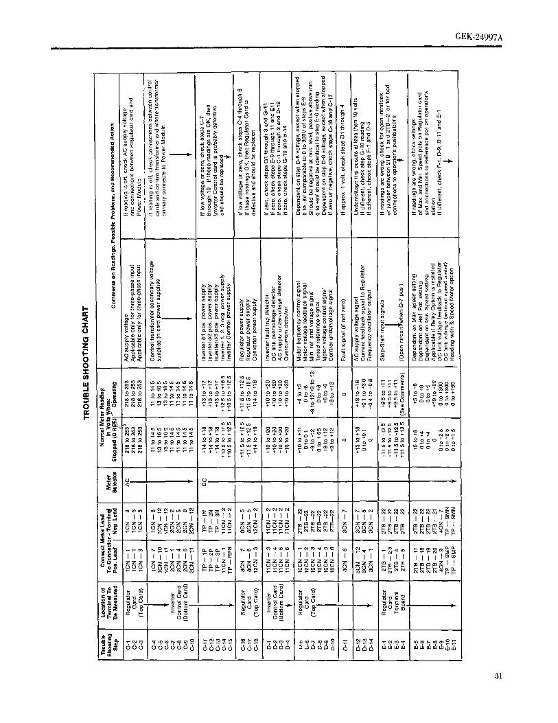
GEK-24997A
0 _ 0
o$
§ > o _ _:m ,..,0 _ xo a_ x , -: _: E ' a_.w_,o._ _='_ _ _= ' - - -
o0_ o---- o,. o. o.o.. o
r._q:_ _oo -- o
==== &_==_E
Eo): e 'O E O__ _ _ -- 6666 c00--_=o-- 0.0 0 0 0._
· __ _ .... mo03o_ _- D== =_°o _-_=
§
o _-o__
=== _eoO =_ coo _ c _m000 z_z:eo o e) _n
o _§§ _ _ _ __....... Oo -O. O. O.C._ C 0 O0 (D --
§ "-=0 , <<< : _= = =_c_c _:_:o Eo<o :E'_:-:_O u. om _ = ooo<omcc
olU3U3U3U3 _ .
O3O3 1'41'- _04 O4 O0 O0 0 _ I._ = = _ __ _++++ _'T_' ++++ +_,++ ,¥ ¥T ° +++E T+_+oo
. i_-=Q_ _._°°.....o o ooo oo _° oo_ .... o Oo_oOo oo_ _ --....... ___o_ -- o oO+ + +
_ ooo
O4('4 _ tO tO tOtO tO tO
o ._ ooo oo o0o oo o ooo o__. _o o + ooo o + + +_- o o oo o o o _ _ o o (:3 _ o _° _ _ o o o
_" ¥¥_o _-¥ ++++ ¥ ,o++ _ ro .... ooorr rv vvvr
' I I '1 I_o
,° II I......I I I i ] I I I I i izz i zzzz
._. z_ z_._Z_ooo _lZ_ _ _ _i._._ O0 000_ _ ; ma. 0000 _-_-_-_- _)0z m_mmm mmmmz I I,_ _ _ F-_ oo_ _ _ ¢u e4 ¢_ _4 _ 0303 i r,i_lol r,i c_ o_ c,_r,:..*i_ i_
_-- I
___ la: I I I I I I I I I I I I I I I I I I I I I__o._°'_ I I I I I I IIz I Iz I zz_ zzzz zzzzzz I II-mt-t-_ _ z_ _o oo_ooooOOOOOOO_ _ _ _ _
om__ -- om
_0, _ e,I ¢0 ..::r_o _ i-.- ¢o o_ _,_ _ cu eo ._- _o r.o i,,- ¢o _ o,1c,) ,._- ,o ,,o i,,..co o_ _0 _ cu o') ._- _ _ o3 .,_. u") ,,o b, a0 o'_O_
_o_ 666 6666666 rvvv_ .......ooooo 666 6666 _66666 I6 666 '"'_'"'""..'.,.',..',,,',.5,.,,.,,,
i
41

GEk-J4907
- _ =_ _ _ _ -_ ,8 _ -_ _,_gE
u. _ n _ 0 >_o o _-- _ _ o _ _:=
[_ o,,- ,,, _. 8_..._ ._E , _ o=-_
m
I_ _ _- _ _ _ _ _§ '80 _ - ,_ _ = = = =_
_-_-_.o. _ M_ _==_ _ _ -: I I I I I I _=o
_ := ......
< _g oo cc mm 0ooo oo x_>g o _:mmm_0 {
_ _ o _o ;'+ oo ?T+ 99 o o o _ RooR oo soo _ o ooo ooo o oo o_ . o_ _ oo _
(:3 -_o _ ++ ++ _+o _ ooooo+o++++oo _T _ _ _ _,,++_ _'"' _ _ ,
¥ ?¥+_T¥ E E _ v+ +_ ¥ E v¥¥vo ooo . ooo _o---_s + oo oo _ ooos oo oo
_ ,"3
" I } r
,,, ,, ,, ,, ,, ,, mi,, ,, ,,,,<,, ,,,
_o., z zzzzz z z zz z I zz' o__ 8o y__ooo 0 _ mm mmmmI
'o'_i --
I *°{ -- j J_
_om '" ,,',,',..L,,',,' i,,',,' oo_ oo_ 0 _ ' ' 4_ ---S-_ _ 4-4

' (; EK-24997 t! i a
3. (:onh'oller ca. be slatted, but shut'; down when B. (;o,thcdh_r ()pmale,, Inq.'<)pcrlyoperator's speed p(ilellttonleter t_ im'reased.
a) If the RUN light on the Regulator card blinks at a 1. Cannot obtalti raled frequem'y and ',peed 0't-'oklow frequency when the Start pushbutton is controllel and motor nan.'plah, rating,s)pressed, wtth the speed poi at zero, tlr(, controller
ps in an operatingcon&tmn. If it shuth down as a) Check reference vohage by going through
soon as Ihe speed pot is increased up to 10%, Trouble Shooting (:hall ,,,lep,,E-ti ami I)-8. It Itt(, 'disconnect AC supply power and go lhrough D-8 voltage ]s les,, Il,tn the E-l) voltage, chec.kTrouble Shooting Chart step B (page 42). If $1eltI)-13 and (;-10 for an overload cra{ditto,.
faulty rea,lings are obtained, goto Power Module (:beck Iht moh)r ('urrelll will! a elamlD-ml[nvertel Section or DC 13nk Filler ammet,r and emnpare with Iltec{mtrolleroullmlTroubleshooting for further instructmns. {'urrenl rating and molor eurr{qtl taling. If thc
motor culre, nl ih lc,,, than raled, try m('rea,,mg
b) If Trouble Shooting Chart step B readings are all (turning (:W) the CLIM (ct,riehl h.,I) lint mtsatisfactory, go through stepG. Iffauhyreadings the Regulator card Itt see fl flu,, adjuqment ih
are oblained, go to Control Card keeping the speed beh_wthe tetelen.'c,,ctting. IfTroubleshooting. the motor cur{Piti IS hlghcq [hall rated,
]llvestlgah. the reason htr the overload.c) If Trouble Shooting (',hart step G (page 42)
readings are all satisfactory, or if the controller b) If the I)-8 vohagc l,,,the ',amc as the E-6 vohage,shuts down at a higher speed pot setting, go as mea'mred m ',lep A, bul 1,%le_$ lhall ['½.5vcdl,',,
through ,,lep l) (page 41). if faulty readings are h'y mcrea,,ing (turning (]W) tit{' MAXS (max
obtai,cd, go lo lite Control (:ard ,peed) poi on the Ilcgulahn c,'ud. II Iht ,,itecdTronble',hm:,llng (page 45) {or further mcrea,',e,,,, adlusl M,4XS to .bi;cl. Iht' dc..','dinstruct,ms, speed its long as I)-8 ami I':-(>wthagcs do not
exceed 8.5 v,dts. See Ih'gulat.r (:a,dAdjustment,% in Sm'Iron 5.0 for more
4. Controller dints down occastonally when running, instruc:tton,%. Il t[te .N)c'c,d(to(,s m)l inclea.,,e,but can be ,'(,started and runs properly, return thc' MAXS IDOllcd]ts original setting and
proceed lcdthe uext st.p.a) Disconnect AC power and check for loose
connectmns at controller terminal boards ITB e) Check the voltage control signal of step 1)-9 iiiand 2T[I Also, check for loose or shorted the Troulde Shooting (:hart. If this vohage tseonnectmns to the motor and in the operator's more negative than -9 volts, check the D(: link
control slat]on, vollage al sit, l} l,]-i) and Iht A(: ..iqDly vohage Itl
steps C-I Ihrough 3. It the At: supply voltage isb) Check for possibility ot intermittent grounds in correct and the ItC link voltage is over 30 volts
the motor or motor wiring. Disconnect the higher than the AC supply vohage for single-controlh, from the motor wiring before phaselnput drives, or ihover 60 volts}ngher for
meggermg the motor or motor wrong for three-phase input drives, then {educe (turngrounds. CCW) the l//ttz (vohs/hertz) poi on lire
Regulator card to obtain a step ILOvoltage les,4
c) Check for any source of electrical noise on the negative tllan-9 volts. Il tile ACsulqtlv vollage tsAC supply lines or in wiring in tire same condmt less than 218 volts, th.,, (,oildill(tll i.., mil of
as AFtrol ! controller wiring. Supprehs the ('ods specificatmns and must be corrected.of relays, contactors, solenoids, brakes, etc., il'in
ch)se prcDximity. Use an R(: circuit (0.5 MF d) 1t the ploblem callII()l lie found, The Regulah,capacitor ,t series with 220 ohm resistor) across card may tit' defective and shouht Irc repla,'ed.the coil Icrminals for suppression. See Sel'llon 7.0 lilSlrtl(.llOllS.
d) Reter tit Miscellaneous Truubleshootmg Checks.) (page49).
1,3

1,Ek-:2 I,_q7_- _......................................................
2. M.tor operatmn i- rough .r unsl,tble a) (]he( k the Stop-Start input qgHal_m step,,, 1_]-]
through E-4 of the Trouble ,"qhoot]ng f;ilatt.ti) Check settl)lg cd COMP (IR cmnpensation) pot PIe*.ing the Sto I}pushbutton .hould cause E-1
., thc Regulat.r card. Too h_gh a setting at low through E-3 to go to their ncgat,ve, stopped,q,eed, I,ght load operation will cause motor readings imme&ately. Iftheydm?t,eheckwmng
"cogging" and tansy opratmn, and may produce and connectmns between controller andexecs,we curreut 'Fry turning the COMP pot operator's statmns. If they do, proceed to step
(](]W to reduce lhe amount of 1Rcompensation. 4lb)
b) It insla}nhty occurs m currenl hmtt (overload) b) Check Trouble Shooting Chart steps D-6throughnper,tlmn, or ol turs when usmg tile Follower D-9, D-6 and D-8 should go to zero and D-7Option card to tollowa digital reference signal, should switch to negative at the end of thetry mc)easing (lurning CW) the LTIM (linear deceleration time after the Sh,p pushbutton is
time) pot settiug, operated.If D-7remainspostt_ve,cheekthe DClink voltage step E-9, If this vcAtagedoes not go
e) (]heck for uneven motor loading, mtermment below 8 volts, the Regulator card is probablygrounds or var_ mg AC supply voltage, defecuve and should be replaced. See Section 7.0
for ms)ructions.
3. (];tit)t(}[ control motor speed with speedpotenlmme, ter 5. Motor rotatmn cannot be reversed (requires
6VRK] 1K Reversing Opnon card).a) (]}leek Ihal Itu' lumper between Regulator card
post_ FCI and 1'(:2 }sin place. (This jumper must a) Go through Trouble Shooting Chart step H
be removed if lhe 6VFllK Follower Ophon card readings. Reversing will oc_ur only at theis colmected) stoppedconditionwhenthe tt 3readmgmlow(:0
to 2 volts). If the Re.versing card is defective andb) (',heel, releren, e w)hage by going through should be replaced, refer to Section 7.,0 for
Trnulde SlmolBngChalt steps E-5 through E-8 instructions.ami I)-8. If thc I)-8 vohage is leas than E-6
voltage, cheek -lops D-13 and (;-IO for overloadeomlllmn. (:In'4k the motor current wdh a 6. Controller will not follow external refer,eh,cesl_aa,l
elaml,-ml arum, let and compare with the power (when using 6VFllK Follower ()lmm).ca,rd).,uml uulpul curry'n) rall/lg alit] motor _urrent
,ra[iI4g.11lite m,,Im',current ts les,, than rated, try a) Cheek that t}_ejumper between Reg.u[a,t,o_,em_d,n)('t;e,u,nlg (lul nmg (]W) thc CLIM (_urrent post FC1 and FC2 has been removed.,limi.l) pot on Ihe Regulator card lo see if Ilns
adj,uslmenl is keeping the ,,peed below ,l'he b) Ch,eck for proper jumper placeme.m oa,_l,.h,erN'erence selhng. Follower card dependen_l m) the ,desa,r,{d
operating mode and input _tgna[ level, l)h,e,e.k
c) ,It sleps I'M)and I)-8 collage are ()K, but ac.ps E-9 adju,tments of Folhlw card p,lentmmeters ,('Seetlnongh E-Il reading,, art' Iow, go through Follower Card in Sectmn 8.0 for l.um._erTt)mblc Sllnullng Charl step F It) determine ti' placement and pntentlomcter a,dj,usft_m,e_a_l[herc, lb'"'d pl'(lhleIII ii} Ih(' convetter control. Ab,o, instructions)
teter lo (:on)roi (:ard Troubleshooting.c) (;o through Trouble Shooting (;hart step J ,(,page
421 readings. If it appears thai lhe Foil.ow,e,),ca.r,d'1. t]annot slop mohu t_, defective and dmuld be .eplaced, re/er to
$e¢llOn 7 0 lilSlrttlt'llq}llS.
Nc}Ie: If lnldor I,tHIl()t Il(' qtopl_ed b;' the normal
mcan. inhq rupt \C supply power to thee-Illr, lle!
'Vl

" (,EK-249q7AUl= i ....... , i,ml .
CONTROL. CARD TROUBLESHOOTING (see Fig. 19) There are live tauh detectors on thc two contr.l cald,,whwh are checked n] Trouble Shoaling Chart .'qep.', Ii-]
The two mare control cards are mounted together Ia Im'm through 1)-4 and D-10. The DC link overvoltage detector
lhe (:mlfrol Card assembly in tile £ront compartment o£lhc (steps D-2), AC supply undervo]tage delech,' (.',h'p D-3I,
controller. The Regulator card is the top card m thc overcurrent detector (step D-4),and conhol undervoltage
a,,sembly and the Inverter Control card l.,, the holhnn card. detector (step D-lO) ,should indicate a fault (by gmng lo
ThelfeversingOptiolJc, ardamllhcl%lh_werOpt]micald(il zero or negative) only during the tmle Ihal lilt, fault[urn.,,he.I) a.'e re,mn{ed to the Regulator card condition is actually present, Therefore, the additional
'l'roubh,,,h.otmg of ail at the.,,e card,, {'all normally be &,nc checks called for ltl the Trouble Sht:,ollng Chart shouht lit,
with.ut dlscun,et'ting al removing lhe card,,, made immediately lo determine If a fault condition acluallyexists, or if trouble ]sa result of mlsoperati,m o[ tile [;mh
The cmd a,,,,',emhly can be rotated and latched in all uln'lght detector. Normally, the actual fault eond]lmn di,,appcal,,,pontoon h)r better acee,,,s during trouble,,,hoi)tiug a', soon after the fault mp occurs, with the detector returning
fi_ll.ws: (,;ce Figures 24 & 2lA) to its normal stale after setting a fau]! latch im _}l_'Regulator card.
I. IMease tile Mt and right card as,4cmbly lalche,,located at the lower sute.,, of the !uvcrter (:mltrt)] 'The hlverter Fault detector (step D-I) operalc,, dd't'erenib,
(lmttom) ,'aid. lmm the others. Tin, detector indicate.,, (by going Il)/.Ct(0
when any transistor u, lurned off by its j;mtecltve ('{rcuH.
'2. Swing Ilw cai d ut,ward until .I ,,lilp,'-,(approxJmah']; This is a part at each transistor driver clrclut. This (h'h'('[(}l
I lO° ) and lah'h by cx{cmhng I}w lah'h bar Illal i,, also indicates whem.vcr the tran.%l,,Iol,, ale lilt'ned ()ti }ivhicah.d on tilt' bollonl Jig}it Mdc at Ibc cal,I any other fault dete('tol, and lerllalllS [ndical[i{g for,l.,, b)ng
a.'.,'.,cnl[)iybracket, as the D(: hnk vohagc (steps (;-Il (it [']-9) i., almvcal)proximately 15 volt.% This pleVerll'_ ['ehlartulg Ill('
It card {eumwtl or rephn'emcnt beclmms ne('e',saly rciel It) ('ontro/h,r after a tault ,,'nuldown unli/thc I)_; hnk vohagcSeclmn 7A has dl.,,charged to a Iow value.
CAUTION The fault latch on the Regulatm card is set whenever a I'au[Ioccurs. Tu reset this latch and restart the controller Il(: link
IF THE REGULATOR (:Al/l) OI/FOLLOWER OPTI()N v()ltage mu.,,{ Liebelow approximately 15 volt,,, an(t the Shq)
[:&RI) ARE BEPLA(:ED, Till'; NEW CAIll) SIt()tlI,D pu,,,h[mtton nmst he pre,','_ed bef, re pre.,,,,,mg the StallH.\\'I,: Till': SAME IqITENTIOMETI,:II SETTINCS ,\NI) pushbutton. If the I)C hnk voltage does not gel below 15
FIlE SAME .lUMPER [)I,\(;EMI';NrI'S AS Tile (il.I) volts because of cop. verier leakage cmrcnl,dl.,,connect M'[:',,t'H). NI)'I'ETI{EI'IIEI. Ii)IISCAIIIISETTINf;SPI{I()It power until the I)(: link voltage }las been dl.',charg('d.
I'() BEM(}VAL. Reapply ACpower attd it dmuld then be }ms.,,dlle to ,,tart the,'ontruller. Il tile controller ('ann(il be Marled (Ill{' ti) Ilw
l'he contra[ circuitry ou thc upper half of tile I/egulatm fault detector (steps 1)-1 through IL'f) indicating cveu
:'ard. adjaccnl ti) the ,'ontrul ternltnal Il(laid, I.', al ,'.is{' though ti() fault exists, the Inverler (:{,r,lr{d card i,.
_l'mtnd w,dentm(,a', al,,'a{lcu'eutt', c,uuec(ed lo tEwcoutl,I probably defective aud 4,)uld bc rel;laccd.!et'mmal l,,ard 2'1'1/ The ,'.,ll.I ('Il ctlitry ()il [lie lower })all
)1 lite [Iegu[alo[ ('aid and all thc circuitry au the Invcrtel The diagnostle .sign,d%measured m ,.,h_p,, I)-5 flu',,ugh I)-9::ant roi card, are at ,,eve{ al dill'el {'tit powc[ [latent{al,,. (if the Trouble Sboohng (:hart indwale the ,peratmn (ii Ihe
ReguIator card. The voltage reading,, given {ii Ill{,
WARNING 'operating" column for .,,reps D-5, 1)-6, Il-8 and l)-9 will
vary Ir,ira approxnnately tile first value at zero le_erell('e
:;REAT CMIE SIlO[II,I) BE I1SED IN TAKIN(; and speed, ti, approxmlately the second valueat nlaxlmunl:()NTIIOI, (;[['/(:[llrl ' IlEAl)IN(iS SINCE MAN5 reference and speed. The step D-7 reading ,,h,mld lie
:IItCIIITS Alii': AT Iii)WEll P()TENTI _I,S. A%()II) negaflve al nunimum re£ercnce aud voltage, and ,h,,uh!
'I';I{S()N \l, (:ONT\I:T %_ri'Il 'l'lfl,;Sl,: (:ll/(:l;J'/'", \Nil switch h; pu.,,]llve at approxmlale/y 5% at rated tl'Jer('lW(,
l'_kl'; (,\lIE N()'I' Ti) SIt(lilT III';TWt;I';N (:IIIt:I,ITS and vohage. If ally (.*J fhe.',e rea(hng.,, ar(' apprccial,ly_'ItI':NT\KIN(;III';,\I)IN(;S. ihfferent from mirrnal, tJu,s ,,h,luhl Imhcale Ih('
rnisoperatmn pr,)bh'm area. If Ihe prid,lem appeal, h, tic _l)the ('ontr{)[ rather lJlan in Ibc power cir(.llH',, tile fleguLah,i
card r-;pr{_bably de/et'live and ,,hould be reph, ccd.
1.5

( ;!:,K-2t,gg7
wm r rni
Tl_.ubh' ,q.hoolilng ( :hart qep F check,_ Ilit; .peratmn of the(',mvethq (;mttr(d (m Ibc Regulator (.ald. It these reading'_md. at(, lilt. lh'gulat-r card la delectJve, It should helcphn'ed.
Tt.uhh' qhooltng {]hart step G check,, the operation of theinv(.rh.r (](,.ll,,I Il Iho.;f. reachngs mdn'ate Ihe h.verter
('.nll.I c...t I..Mc_ liw'. it 4muhl l.' repla.'ed.
POWER MODULE TROUBLE SHOOTING
The power m.,lule assembly consl_;t_ of 1 or 2 SCRc(mverlm re.dub,s, p-wer transistor.,, power module cardand control transformer all mounted on a single heatsink.The power module can be funchonally broken down intotwo sections for trouhleshootmg as follows:
A. (:onverteE Sectmnd
The powm module converter section consists of theS¢;FIcomcrter modules with MOV and RC snubber
pr.tect_v, clrcuils located on the power module card.To help in Irtmbleahooting thi,, section, refer to thePower ,M,dnh, elementary diagrams for thectmtrolh,i lIP rating being checked (see Figure',g, II),IOA ,md I l).
1. (:becking S(:R (q)nverter modules (with supplypow,,I di.cmmected). Tim SCFI modules can bechecked by removing the lmtl{)m plastic bat rle_(sec ]ustrtlctltms in Section 7B) Ifa faulty S(;Rbridge Is ,.,txs[)ccled, disconnect the 4CN,5CN ami6(]N rd)hon cables f'rt)m their t,onnectors on the
J).wcr M.dulc (;ard and pu,,h them to one side togain acces_ I- the SCR bridges. Disconnect tilt,wn'e,, to thc ,,_x,,tat)-tm c(mne('tor,_ o£each S(',R
t)ack.tgo (,4ce Iqg. 38), kectung a record of whichw.c.g.l, which lei IlUIlaJ:",, I lSlllga muhi-meter.,ch,_I,'d I- I Ix m' 2Ix ,. ah'. check the re4,qam'e
J)_'lw,'cn lelnlinaJ_ per thc f-Ilow]ng table:
1.O

(; EK-24997 4i i ,, lin
SCR MODULE CHECK LIST
, , ]
(:on*itel Nh'for I,cad '1'. '_h.n,r Ilcading m ()inn. !,, ]
!Positive I,ead Negalive I,ead (;()(),t Ikl,I , j
,\CI + lO0k I_)int. () h, Ix.\(12 + lOOK t- mt. 11t. ixAC1 -- lOOK lomi. (){_,k
4(22 -- lOOK t,mi. ()I. k+ ACI lOOK I. snl. O It, ix+ AC2 lOOK lo,hi. I)t. ix
-- ,\CI O.IK loIK ()h, Is11.
-- .\C2 OIKn, IK ()1,,I,,I-- + O.lkh,Iix ()n,int.+ -- lOOK {omi IiI,,Ik
+ (;I 1,()to 120_ () l- ,,il+ (;2 1,0I. I2()Q (II. ]iff.
I
II ,my l)ad r,.adings me .blamed. lbat _(]l{ n,(Muh' .,Imi,h{}.',rplaccd.IlelerioSection71)f.rinqruclicu,on S(]I{
M.(h,h'rem.vol.Ariescheckinga:sd/mScl,lacemmilolan,,:,.i,h:, cmcill .I ami c()ml,m,.ist.,,, iii]kc '..ill,' .illdl,,,i (}lili('('{('{{ Wile _, ,Il'{' I('1 ()S:llt'l {iq1 i'()l t re'Ii',.
2. Converter Section Operational Test dtscha:'ges only through the dt_('barge res,sim',which requires one nnnule lo discharge dowu lo
If converter section misoperation is suspected, 50 vt)lis.but all converter section and DC link filter
components appear to be good, the converter The minimum DC link voltage that ca. besection and DC hnk filter portmn of the obtained will depend on the leakage current ,ncontroller may be operated alone, without the S(:R conversion bridges. If the.minunun: D(;operatmg the inverter section or motor, lin'k voltage with controller in Ibc sloppedHowever, the Inverter Section must not have condilmn exceeds 60 writs, th_m one of the SCI(
shorted components, since Dc link voltage will be modules bas excessive leakage ami dmuhl beapplied to it even though it is not operating. The replaced. If the .iinimu.tI)(' link voltagefollowing procedure should he used to perform exceeds 60 wdts only after the Start pnshhuthutthis operational test: ihpres.,ed at nun]taunt rcferem'c selling alsdwill!
the MIN$ pot on lite Regulator card tu: nedfullyWith the AC power supply disconnected, ('CW, then tbere is a ps'oblenl ill thc Regulatordisconnect ribbon cables 3CN,5CN and 6CN card. Refer to Control Card Troubh-shoolsngandfrom the Inverter Control card (bottom card of to Trouble Shooting (]hart siep, I)-5 thrmigh li-the control card assembly.) Apply AC power and l0 and steps. F-I through F-9.start and operate the controller in the normal
manner. If the Converter sect,on and the Il the DClink voltagecatmot hecontrolted by theConverter Control on the Regulator card is operalor's speed polentiometer over st,, entireoperating correctly, the DC link voltage as range tip to at least 250 vohs (dependent on themeasured between test points SMP and SMN on F/llz pot setting ,iii tit,' Regulator card), a
the Regulator card, should be controllable over llnddcnl on the Regt.latm' .'ard tu.bably exs_tsthe whole operating range by the operator's Rele] to Control Card '!'rotddesh,,.tmg aud tospeed poleniionieter, ttowever, lilt: Trlmble Shoolsug(]hart qh'lr4 I).5 II. ough I)-IO"deeeleratnm" tune will be much longer Itsan ami sleps F-I througlv'l;'-9.normal because the Ii(] hnk fiher capacih:r
1,7

z
(;l",K-2 _997,\
11.Inverter Section
The power module lnverler ,4eclion con,,i,,ts of thep(Tw,'r tran,q,4hTrs with RC snul,ber c]rcmts, base
reslsh,rs, and loading resz,,tors hTcated on the powermodule curd. 'l'o hel l, ill troubleshooting thxs .,,eot,on,refer h, tl,e Power Module elementary diagrams fortbe controller HI' rating being checked (see Figures9,10,10A and 1l).
1. Checking inverter section p,wer transistors andsnubbers.
If a defective transistor is suspected from goingthrough Step B of the Trouble Shoot,ng Chart,remove the lower plastic barrier as explained inSection 7B.Disconnect the motor lead,,, at terminal board
1TBpoints TI,T2 and T3 (sec Figures 16and 17).Disconnect the 5CNand 6CN ribbon cables, the 2
power leads (from the link filter reactor andcapacitor) on the stud connection point at P2,and the N2 connection at the shunt on the powermodule card. Using a multnneter selected to theIK or 2K scale, check the resistance between
terminals per the following table'
TRANSISTOR CHECK LIST
(:mmc(l Meier 1,(',.I '1'. Meier [_('tl(llllg ltl ()bins
I'_,,]liwl.(.ad Negativel,ead Good Bad
I)2 TI (E) Infinity 01'2 T2 (E) lnfm,ty 01'2 T?, (E) l,Tfi,Hty 0TI TI,(E) lnfm,ty 0T2 TS(E) Inhmly 0'l',_ T6(E) l,ff,,,ny 0
TI 1(1',) 1'2 0.2k to IK 0 or mt.T21 (E) 1'2 0 2k to 1k 0 (7,'int.
T31(E) 1'2 0.2K t- 1K 0 or mfTrl (1';) TI 0 2K to 1K O -r i,d.T5 (E) T2 0.2K to IK 0 .r mi.'1'(, (1'3 T3 0 2k m l K 0 or nil.
TI (B) TII(E) 31)0 t(, 200 _ 0 or (nfT2 (B) '1'21(E) 30 f} t. 200 0 0 or ,,il',
'1'3 (B) T31(E) 30 0 h, 200 _ 0 .r inf.TI (B) TI, I (E) 30 0 Io 200 _ 0 ()r mt
'1'5 (Il) TS1 (E) 30 _ 1(7200 ;q () ,,r mf,'1'0 (B) T61 (E) 30 _ t. 200 0 0 ,)r ir,l,
18

' (;Ek.2$qt}7 a
Il :.n_ [)a,Jread,r.g,.,ueobi.nm'd..h.c.nn(,, ! Iht DC LINK FILTER TROUBLESHOOTINGba'-,(' (ltl slid ('rrlllhq* (]']) lead,., il(till Iht'IF
h'rmtnat]ons and r('('hc('k the le',],la,,, c Tile !)(' link filter cons,st_ of the biter cbt)kc(.,) and Ihc
readings. If they are Ille same ;is Itch)r(', thc filter capacitors. Always disconnect AC power and wa,l for
hans,.,tor ,,hould be replaced. Reh'r lo Sccl,,,, several minutes before checking Ihe It(] hnk fiher7E for ,nstructn)n,, ()n rej)laeen,enl (d ItnJ(.d components.I,'ansi.,t(),.,. Refe,' to Set'trim 9.0 for ,parc pa,l,h_,tings.
I. Filter Capacitors (see Figures 35 & 37)1t the d,sconnected h'an,,isior rea(hug,, are good.then the -r,ginal bad ,e,,lt,g i,, cau,,ed 1); ('lib(.} This consists of either one (1CF) or two (ICF & 2(3")aH(tiber tl;)n'.i',h)l (ti a lalh.,{ _,lul)t)(.t ,',r(',,)l electrolytic capacitors connected m l)aralh'l between
P2 and N I. When the ('outrolh.r has not tlccn ()pc,ah,d
2. Inverter Section Operational Test fro six months or more, the filter capacih)r,, may ,,,hirlto degrade and their leakage current iht'react ,X
If inverter misoperation is suspected, but all procedure called "forming" may I)e ,c('c',.',arv toinverter section components appear to begood, return thc electro-lytw capacator, lc) dnm' ratt,d
the inverter section of the power module may' be operating capabfiity. Reter to Sect,on 5.0 Ior f. rmmgoperated alone, without power from the instructions.converter section. However, the converter
section must not have shorted components since Electolytic capacitors can fail tiy d_orting, can exhdntpower will be applied to it. Operating the inverter excessive leakage current or can dry up ami lose lhetrsection with no voltage m the DC link allows capacitance. Thc latter usually result, t',om a ruptured
checking the inverter control card operation and vent plug due to "gassing" of excessive i'm rent and/orinverter section power transistor base drive and temperature.
switching operation without being concernedabout fault trips ff mlsoperation occurs. The The filter capacitors can be checked by removing thefollowing procedure should be used to perform bottom plastic, barrier (se(: mstru('tit)_ in Section 7Bt.
If a slit), ted capacitor i%suspected ti,s( ,nm'ct thc wire.,,the operational test:
With AC power supplydisconnected,disconnect to one terminal of each capacitor. (.beck acr(),4, theribbon cable 4CN from Regulator Control card. ternunals of each capacitor w,th muh,mele,, sele('tedApply AC power and start arid operate the to the 1Kor 2K scale. A shorted capacllt)r wdl read zcr.controller in the normal manner. The Converter or a low resistance while agood capacm)r w,ll charge up
Section will not be operated, so the hnk voltage to infinite impedance (un that scale). Any ,horted (,will be less than 2 volts (unless the AC motor is leaky capacitors should be .cplaced The ,cmainmg
disconnected). It should be possible to operate capacitors should be checked for ruplured or mis,,ingvent plugs. These art: round plug.',, al)proximatelythe inverter from its minimum frequency up to3/16" m diameter, between the ternunal,. If' a plug i,_about one-half maximum frequency, the upper
frequency being limited by the DC link voltage ruptured, it does not cause an ,mined,ate capacitorbeing essentially zero. If the inverter trips out o,' failure, but will result ir, gradual los,, ()_cal)ac,ta,('ecannot be started, go through steps D-1 through Any capacitor with ruptured })lugs shouh{ be ret)hi'edD-4 and I)-10 and D-1I of the Trouble Sht)otmg a', _oon as possible.(;}tart. If the inverter can be started but operatesincorrectly, go theougll steps D-5 through l)-8 2. Fdter Choke(s) (see F,g. 42)and G-1 through G-9 (tn the Trouble Sh()oting(;bart. Also, refer to C()ntrol (:ard This consists of either one (1 l,F) ortwo(ll,F&21,F)
Troubleshooting. iii parallel) chokes connectetl between ltl and I)2.These chokes are mounted m th(' ,car COml)artnlent
near the top of Ihe cast.. The I)C res,,,,lan('e itl the hherchoke (st, from PI t() P2, w,ll })e belwecn .015 ti) .00uhms depending on the rating, th)wev,.r, the re.',,shmi'ehetween the h,rnlinal,4 h) ('ase g,,,und ,,,h()tJhl Itt,mfmile If a taulty choke l,,, ,,u,,pe('h'd, ,,(,e Scott(tn 71for remowll ,nstructit)lis.
1t)

(;Iq_:_1907A.
xlr l
MISCELLANEOUS TROUBLESHOOTING CHECKS D. Looseor Shorted (_onneetions
The I,ilh)wmg check hst of miscellaneous 1terns IS included l. Cheek incoming power connections.n, pmvtde additional directions of investigation m[tlmble4to(_tmg this drive. 2. Check connections to power modules, fiher
capamtor and choke, mrcmt breaker or luxes, etc.x. (;(ruling and Temperature Problems
3. Check outgomg power connections to starters,[. (;beck for suffwent mr flow through power umt. motors, etc.
2. (;beck d mmke air is below 4,0°C. 4. Cheek incoming control wiring connection_.
3. (:heck I-r adjacent heat soun es. 5. Cheek for bent terminals shorting to one another oncontrol eards.
4. {',heck i[ room ventfiatmn is adequate to remove theheat beingproduees. 6. Checkfor brokencard componentsdue to physical
damage.B Input Power
E. Electrmal Nmse
1. Check lot correct voltage (within +10%, -5% ofmmwplale rating) and frequency. 1. Cheek that all external relays, solenoids, brakes,
etc., interfacing with or adjm ent to the power unit2. Cheek for balanced phase vohages, have RC suppressmn on their coils.
3. (:}w('k hlr transmnt over or under vohages. 2. Check for other external somces ofele('trical noiseincluding po,,,_ble plck up in control leads.
4. [lave Irans]ent voltages occu! cd due to lightning orground laulls or power tactm capaettor switching? F. ()utpul l,oad
5. (:beck for excessive hne regulation due to a highmql(:d,m('e (solo Ac supply. 1. Check startmg torque requirements.
6. I, AC ,ullply gTminded or ungrounded? 2. Cheek for transformer saturalmn at low frequenciesit output transformer _s used.
7 I,, the ._vailabh' 4m,t circmt ,'urrent too hlgh'_
3. Cheek for molor overloads tlr jam-ups.8. Al'(' [liele })-wet factor c.rrection capacitors
('auslll_2 harmonle% or their swm'hmg causing
vohage transmnls?
9. /_re [}l('l C excessive bWlt( Inrlg transients or
"nol('}ltllg" .bservable on the AC supply lines (withUti OS('i[ll)%l'Op(*) ?
l: Syqems (;rnunds
1. (;hel'k that the power unit case is properlygr.und_.d.
2 (;h(.ek fro-grounds m nlolor windings or In powercable.', IoIhe motoT.
3. (:he(k tm gr(nm(t_, m i'tmlr,I wiring.

· GEK-24997A
ii i , --
SECTION 7.0 9. If it becomes necessary to replace either card, theycan be separated as follows:
REMOVAL/REPAIR AND REPLACEMENT(a) Remove the ribbon cable connector 3CN from
GENERAL the Regulator and Inverter Control Cards.
This section is supported by a series of photographs (see (b) Remove the slx plastic stand offs that separate
Figs. 20 through 43) which have been arranged in the these two cards.column next to the text, to be of assistance during the
complete assembly of the AFtrol I contoller. (c) Carefully remove the plasnc sheet on the back ofthe Inverter Control Card. (see Fig. 25)
A. The Regulator Card/Inverter Control Card Assembly isbest removed as follows:
10. To reassemble, reverse the above procedure.
1. Disconnect the single-phase (or three phase) AC
input power.
2. Remove ribbon cable connectors 1CN and 4CN
from the Regulator (top) Card (see Fig. 20).
3, Remove ribbon cable connectors 2CN,5CN and 6CN V7
from the Inverter Control (bottom) card. I:g:]
NOTE
CABLE CONNECTOR 3CN CONNECTS THEREGULATOR CARD TO THE INVERTER CONTROLCARD AND SHOULD ONLY BE REMOVEDWHENEVER IT BECOMES NECESSARY TO SEPARATE _THE TWO CARDS.
4, Remove stab-on connectors SMP and SMN. Theseleads are connected to SMP and SMN on 1TB ';'
terminal board for the optzonal speed indicator.
5, Loosen all 22 bottom screws on terminal board 2TB.
(see Fig. 21)
6. Release the left and right (bottom) card assemblylatches (Fzg. 22) and swing the card assembly up toits latched up position (see Figures 23,24 and 24B).
7, Loosen the left and right nuts on the slotted plastic
wire support, hft off the wire support. (see Fig. 25).
Release the cable harness 1CN from the plastic wire FIGURE 20clamp on the back of the Inverter Control card (see AFtrol I controller -- Regulator/InverterFig. 25) Control Cards showing removal of ribbon
cable connectors.8. Carefully withdraw the complete Regulator/Inver-
ter Control card assembly from 2TB terminal boardand the ,dotted card assembly bracket holes. Becareful not do damage the loo,e rd)btm cables. (see(Fig. 26)
51
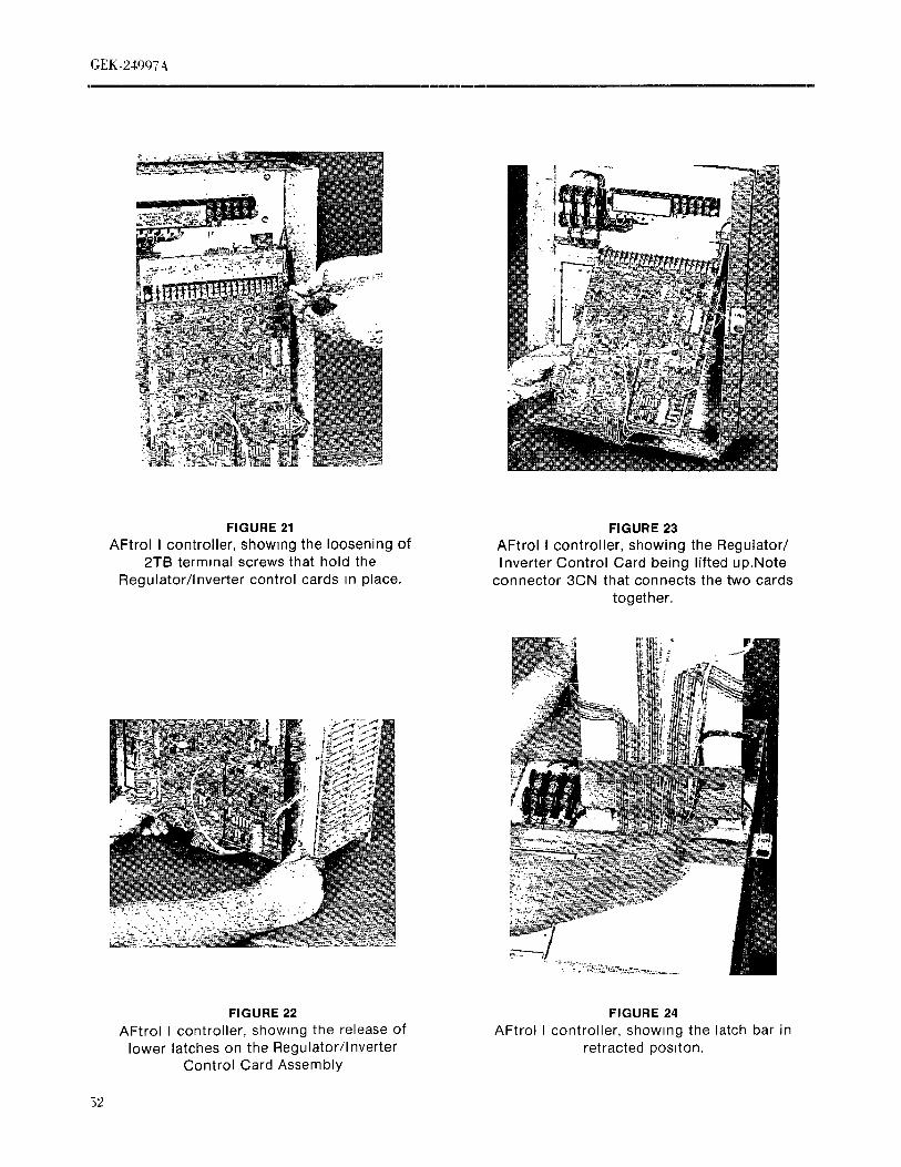
GEK-249q7 4
J
FIGURE 21 FIGURE 23
AFtrol I controller, showing the loosening of AFtrol I controller, showing the Regulator/2TB terminal screws that hold the Inverter Control Card being lifted up. Note
Regulator/inverter control cards _n place, connector 3CN that connects the two cardstogether.
FIGURE 22 FIGURE 24
AFtrol I controller, showing the release of AFtrol I controller, showing the latch bar inlower latches on the Regulator/Inverter retracted poslton.
Control Card Assembly
52

GEK-24997A
%
FIGURE24A FIGURE26
AFtrol I Controller, showing the AFtrol I controller, showing withdrawal ofRegulator/Inverter Card Assembly in Regulator/Inverter Control Card Assembly
latched up position, from 2TB terminal board and slotted hingeholes
FIGURE 25 FIGURE 28AFtrol I controller, showing removal of plastic AFtrol I controller, snowing removal of nutswire support on Regulator/Inverter control holding the lower plastic barrier m place.
card assembly.
53

(;EK-24_Jc_7 \
B. Lower Barrier Removal i
1. Wall mounted (enclosed) controllers:
a. Rame the control card assembly and latch in thatposition (see Figures 24 and 24A).
b. Remove the seven nuts with captive washers thathold the lower barrier in place (see Figures 28and 29) and remove the lower barrier.
c. To reassemble the lower harrier, line up themounting boles and studs and replace the nutsbeing careful to spread out the ribbon cables andwires under the gasket seal.
2. Chassis mounted (open) controllers:a. Raise the control card assembly and latch in that
-_:_" _'_'i:'_'_,_ ,-" '_' position. (see Figures 24 and 24A)
: b. Remove the two nuts with captive washers in thelower right and left corners.
c. Remove the lower barrier by pulling out theFIGURE 28A bottom edge until it clears the two mounting
AFtrol I controller, showing removal of studs, then pull down until the two clips at thelower bamer on chassm mounted umt
top of the lower barrmr clear the top barrmr. (seeFigure 28A)
d. To reassemble the lower barrier, hook the two
chps at the top of the lower barrier under theedge of the upper barrier being careful not todamage the ribbon cables or wires. Then push thebottom edge m while lining up the mountingholes and studs and replace the two mountingnuts.
_, _ C.CapacitorAssembly.
NOTE
The assembly is composed of 2200 MFD, 400 Voltcapacitors clamped to a mounting plate.The number of capacitors prowded are as follows:
Number of Capacitors
AftrolDrive_HP Prowdeda 1 and 1-1/2 HP (1 ph. input) 1
2 and3 HP (1ph. input) 2
FIGURE 29 2 and 3 HP (3 ph. input) 1AFtrol controller, showing the lower plastic 5 and 7-1/2 HP (3 ph. input) 2
barrier removed
54
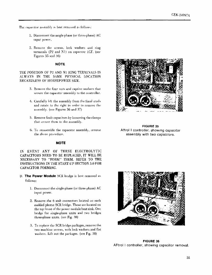
GEK-24997Ai
The capac,tor assembly ,_ best renrmved a_;follows:
1. Disconnect the single-phase (or three-phasd) ACinput power.
2. Remove the screws, lock washers and ringterminals (P2 and N1) on capacitor 1CF. (seeFigures 35 and 36)
NOTE
THE POSITION OF P2 AND N1 RING TERMINALS ISALWAYS IN THE SAME PHYSICAL LOCATIONREGARDLESSOFHORSEPOWERSIZE. ia
3. Remove the four nuts and captive washers thatsecure the capamtor assembly to the controller.
4. Carefully hit the assembly from the fixed studsand rotate to the right in order to remove theassembly.(seeFigures36and37) ......... :_.
5. Remove fault capacitors by loosening the clampsthat secure them to the assembly.
FIGURE 356. To reassemble the capacitor assembly, reverse Aftrol I controller, showing capacitor
the above procedure, assembly with two capacitors.
NOTE
IN EVENT ANY OF THESE ELECTROLYTICCAPACITORS NEED TO BE REPLACED, IT WILL BENECESSARY TO "FORM" THEM. REFER TO THEINSTRUCTIONS IN THE START-UP SECTION 5.0 FORCAPACITOR FORMING.
D. The Power Module SCR bridge is best removed asfollows:
1. Disconnect the single-phase (or three-phase) AC
input power.
2. Remove the 6 stab connectors located on each
molded plastm SCR bridge. These are located onthe top front of the power module heat sink. Onebridge for single-phase units and two bridgesthree-phase umts. (see Fig. 38)
3. To replace the SCR bridge packages, remove thetwo machine screws, with lock washers and flat
washers. Lift out the packages. (see Fig. 38)
FIGURE 36
AFtrol I controller, showing capacitor removal.
55

CEK-2 _97A
NOTE
JUST BEFORE ASSEMBLING THE SCR BRIDGE
MODULE(S) REMOVE ANY FOREIGN MATERIAL BYWIPING WITH A LINT-FREE CLOTH. APPLY A THIN(;OAT OF THERMAL GREASE, GENERAL ELECTRIC,
G3221, VERSILUBE PLUS (OR EQUIVALENT) TO THE84CK OF 'FIIE SCR BRIDGE MODULE(S). WHEN THEMODULE(S) IS TIGHTENED DOWN, THE EXCESSTHERMAl, (;RE4SE MIYSTBE REMOVED FROM THEHE_tT SINK a,ROUND THE SCR BRIDGEt' \_X_GE(S).
E Power Tran,,i,,tor Removal:
1. Disconnect the AC input power.
2. Remove the bottom plastxc barrier (see Item B)
3. Remove tile 3 stab connectors on the transistor.
(Black wire is collector, red wtre is emitter and thewhite wire is base)
FIGURE 37 4. Remove the two machine screws with flat and lockAFtrollcontroller, showmgthecapacltor washers that hold the transitor. Lift out the
assembly removed transi_tor. (see Fig. 38A_
5. To install the transistor, repeat the aboveprocedure.
NOTE
PRIOR TO REASSEMBLING, iNSPECT THE FLATSURFACES OF THE POWER TRANSISTORS(S) AND
_!_L,_ t FHEIR RESPECTIVE HEAT SINK(S). THESESl_JRFACES SHOULD BE WIPED CLEAN WITH A LINTFREE CLOTH. APPLY A THIN COAT OF THERMAL
GREa,SE, GENERAL ELECTRIC G322L, VERSILUBE
PLUS (OR EQUIVALENT) TO THE HEAT SINKSURFACE(S) WHEN THE TRANSISTORS AREI'IGHTENED DOWN, THE EXCESS THERMAL GREASEMIST BE REMOVED FROM IN BACK OF THE HEAT
SINK(S).
FIGURE 38AFtrol I controller, showing the removal
of the $CR bridges from the Power Module,
56

(,EK-24907Ai [ i , ,u, i i i i i
F l',,wc, Module (;ard Removal: (;. IT\ (:,mt,,,I I'._,., T,'a,i.q',,r,,,,.r I{,',,.,val:
I. l)isconnect tile AC input power. 1. l),,,c,m,ie,'t Ihe AC ulpul [roWel'.
2. Remove the bottom plastic barrier (see Sectton 7111. 2. Remove the bottom pla,,ic barru, r (see Section 7B).
3. Disconnect the following wires and nbb,m cai,les:' 3. I)incmmect tile following wiles and ribbon cabl,,.,.:
a. Thc 4CN,5(]N and 6CN ribbon cable connectors a. Thc I(;N .md 2(:N ribb,,n cable c{}lllle('lt)rsal Iht
at the card. legulator ,md reverter, t}ntro[ _ard,,,and releasethe ,'abl_.sfi'om thc wn'e ,.,uplmrlami ,'lamp per
b. The base, emitter and collector wires orr each ot ,;eclmn 7A7.
Ihe power transistors (TI I thru T611.b. The three wnes flora tilt, I(:N ]n,rnessCtmlwch,d
c. The six wires lo the 1CV Stir module and Ibe ;it the KI,K2 and K3 hq re,md p._l_on Ihe powerthree wires to the 2CV SCR module on three module card.
phase input controllers., The two ITX ('(}llll'o[ [.qlW('l[Itlll',,{t}l'lll('l' prillltlr)
d. The power input wires at K1,K2 and K3 screw lead'< (bl,,ck) c,mm,ch,,l al Ibc KI and k2type binding posts for three phase mi}ut Icrmmal i,,,,I.,,,,n tin' i},,wel m,}duh','ard.controllers or at KI and K2 for single phase mt}u!controllers, t.. Renmvc thc Iwo mm hine screws wllh flat and lock
wa,,hers thai laslen the tran.,tormer to lin' heat,,ink
c. The two wires froa, the hnk filter chokes and relllt:,¥t' Iht_ transtmmer (Note: ["m' ctl_lt'l'
connected at PI and I>2. a,','es._ to lilt' top ,',crew, I'elllt);e Ihe hardwan,hohhng ibc lop plastic barr.',' I}e, ,,,cotton7,11and
f, The two wires from the hnk fiber capaellms mow' tile baJrwr jusl tar emmgh lo all.w acce.,, loconnected at NI and P2. the ,,'_ew, l,,,i,lg ca,'eful not to damage ,u,v ol Ihe
Wll'e,,, VOlllltq lcd to Ibc dewce,,mi Ihe luurn,r,)g. The three output wires at T1,T2 and T3.
ltl ewmt ITX control tran,,fmmcl m'eds lo he
h. The three wires from the ICN harness connected replac,cd, thc spare trait'dm met ts awtilable Immal the KI,K2 and K3 terminal posts. (;em'ral Eh'ctric (;omi)any wllh win' harm",se,, and
('{,nne,ch}l,, (ple-wil('d) ami slab-on ('(}Illlt'('l()l.Si. The two contol power transformer primary leads K I,K2 and 1,,3along with an mst! u('ti(m .,,heel.{_cc
(black) connected at the K1,K2 terminal posts, l"lgnrc 38(])
_. Remove the five screws with flat and lock washer,, H. Power M,}dule ,\s.,embly I/em.val:that hold thc card in place.
I I)i.,connecl lilt' AC input p,)wer.5. l,itt out the card, If replacing the old card with a new
one, save the wires left on tile ,,Id card as requm, d '2. Remm c tile botlom plaqic Imrricr (,,ce Se,'tlon 7B).to install the new one. (sec Fig. 38B)
3. I)is,.omwct Ibc folh,wmg %ll'eNalllt rlbb()ll ('abh'_:6. To install tire card reverse lire above procedure.
When tightening the screw terminals on thc card, a. The ,14]N,S{]Nand O(]N itbt}ml cable cmlnech}rsbe careful not to exert too much force, as thl,', may al Ihe power moduh' crud.damage the solder connection ot the threaded m',ertlo tile printed circuit card. Also, when instalhng the h. Thc two wires from thc hnk filh,r capaclh,rs
pu,,l,-m] terminal connectiml,,, on /he b<>ald,be cmmecled al N I amt 1"2 mi Ihc power umdtlh,
carctul to ',uppm't the board fr,}m the bottom to card.prevent Il from bending.
,'. 'l'ln' three output wire,, al TI,T2 arid T3 {m IheI)ow(_r module card.
57
(,EK-2 [()97A-- - - . -- .... m mql i
d The power ]npul wi(es al K I,K2 and K3 _,crew I. The choke_ are fastened Io a platethat i_ faqened lo
I_,pe binding po,l,, on the power module crud fo{ Ihe back ca_e on h)ur studs w]lh nul,, and washer,,,
ihree phase t,tput contoller_, or at K1 and K2 lot The choke assembly ha,, one choke on Ibc I-I 1/2
qngle phase controllers, tip s]ngle pha,_e ami 2-3 HI ) th, ee phase eonlrollers.
The 2-3 tip stngle phase and 5-7 1/2 HP three phasee The lwo wi[es from the huk ftlteI chokes at PI eonlrolle]',_ have two chokes mounted on the
and I'2 on {he power module card. assembly, To remove the choke assembly, remove
the four nul,_ and washers that fasten the assemblyt The I(:N and 2CN ribbon, able eottllecto['$ al lite to the back case and lift out the( hoke a,_sentblv. (see
['eguhlto[ and inverter eonlrol card and release Figures 38V and 38G)
lite cables from the wire ,upporl and clamp tier_ectio,, 7A7,
(:A[ITION: The choke assembly ,_hould be supported
]{emove lhe hardware hohhng the heatsink as while the mountmg nuts are bemg removed
f-llow_: since each of the choke_ weighsalqu'ox,male} _, 17 p()lliidq.
a. For I thru 3 ttP controller,, (plate heatsmk),
reniove the four nuls wJth captive washers lhat S. The individual chokes may he removed from lhe
fasten ihe plate lo the mounting brackets and assembly mounting plate by di_,c0nneetmg the wirespull ou! the plate healsink (It m not necessary lo and re,noving the four nuts with lock washer'_ lhal
remove lite mounting brackets that are fastened fasten lite chokes lo the plate, being careful to marklo lhe rear ease.) See Figure 381) the wire_; that were removed to tae]l,tate
reconnect]on.
}). For 5 amt 7 I/2 HP (:onlrolh-r,, (extruded
heat,4,nk), remove the ,,tx nut,s with eapttve 6 To reassemble, reverse Ihe above proccdt,rewa'..,her,-., Itlt(t [it'..,{ell Iht' h(',tlt.,lllk lo lhtl rear t.w,e
ami pull OCli theheatsink, SI-ts art, p,'ov,ded ]n 1. Top Bart(er Hen,oval:
Iht' top part o{ the heal,ink for aeees% to the mils.
See I",gt, re ;t8[": I. Dtsco[inecl the AC input powe,'.
Note: I"(,r e,tslcr aet'e_,,, to the lop nuts. remove lhe '2 Remove Ihe l_legulalor (;ard and lnveTler C,,utrol
hardwale hohting Ihe hq) plastte harrier per Card as _}mwn ]n .,,eelimi 7A.
,.(., tirol 711,and move the barrier juqt enough lo
alh_w a,'vess lo the nuts, being careful not to 3. Remove the followi[_g wtres:(taIl(Hge any of the wu'es c(,,meeted to the dev,ees
t)n the t)arrler, a All (re{going wtre.':, from tertttma[ board iTB.
.q. '1'- }h'as,.emhle. reverse the ,d_ove procedure, b. The wues from do.r tltotl(tled disemnteet switch
lo ITB and Ihe fuse }dock ,i presenlI t'.h()ke 4sse,,thly Renxoval
e. A{{ oulgoing wires from te,nt]nal board 2TB.
I. [){,,col{fleet tilt' At(' input p. wer.
d. The three wtres from 1TB going to T1,T2 and T3'2, R('tnove the hardware hohhng the Iop plaqie barrier lermmals o,t the power module card,
per _,ecliOll 7.1 l,and carefully fi)Id the barrter otll and
down exposlug the choke a,,._.ernl,ly, e The '_qres f,onl the fei,lie core rcaelors
conner led at the K1,K2 and K3 terminal tuunls
,'_, I)lsl'olllleC[ Ihe Iw. wlr(,,_, t((,i]l ltl(' ('{mke assc'mblx (m the power module card tor three phase lilt)Ut
,,I lhe PI and I)2 ('OlllleCllo[] pi)il(D, oil the power controller.., oral K I and K2 lot single phase ]npul({iOl[ll h, ,'at,] COlllrolh'rs.
_'. [{elllove [[lC' live IIUiS with t aplivt' washers h()idlllg
the t.p ba,,ier m }dace on the ouch)seal eonl,'olh,rs
()l l}le lwo fillip, and lwo ,qqev,, on the ( hHs'qi% type
ecmlrollet _ and remove the lo t, bar riel. (set. Ftgu[e41)
58

GEK-24997A
CAUTION: The two nuts in the top corners of theenclosed controllers also hold the front case
in place along with the two nuts in thebottom corners of the front case. If the
controller is in a vertical positron, the twonuts in the bottom corners of the case must
be in place and the front case should besupported while the top barrier is removed.Install the two top nuts m the corners afterremoving the barrier to hold the front casem position until the top barner is replaced.
5. To Install the top barrier, reverse the aboveprocedure.
K. Ferrite Core Reactors
Located on the back of the upper plastic barrier are 3ferrite core reactors. The two or (three) phase wiresfrom the load side of the AC supply fuses FU1-2,
FU2-2 and FU3-2 Of three-phase) each take five ' ?.._,_turns through these fernte cores. These fernte _'_icores reduce AC voltage spikes that can be presenton supply lines.
FIGURE 38AAfter the fernte cores, these w_res terminate at K1,
AFtrol I, controller, showing the removal ofK2 and K3 (three-phase) on the power module card. the power transistors from the Power Module
To remove the ferrite core reactors:
1. Disconnect the AC input power.
2. Remove the top barner per secnon J.
3. Disconnect the w_res from the reactors connected at
FU1-2, FU2-2 and FU3-2 (if three phase).
4. Remove the hardware (screws, nuts and washers)that fasten the reactor to the panel. Note that thescrew holding the reactor may also hold the fuse /block on the front of the panel. Remove the reactorassembly being careful to note the pos,non that _twas mounted in. (see Figure 42)
5. To reassemble, reverse the above procedure. ";
FIGURE 38B
AFtrol I controller, showing the removal ofthe Power Module Card,
59

FIGURE 38C FIGURE 38EAFtrol I controller, showing the Control AFtrollcontroller, showmg Power ModulePower Transformer removed from the Power with extruded heatsink (5-7 1/2 HP)
Module
FIGURE 38D FIGURE 38FAFtrol I controller, showing Power Module AFtrol I controller, showing removal of the
with plate heatsink (1 thru 3 HP) choke assembly
60

GEK-24997A
/,
FIGURE38G FIGURE42AFtrol I controller, showang the choke AFtrol I controller, with upper plastmassembly removed from the controller, barr;ers removed, exposing the choke
assembly and ferrtte core reactors.
FIGURE41 FIGURE43
AFtrol I controller, showmg the Ventdating Fan Assembly for 7 1/2 HPremoval of the upper plastic barrier. Controller, Note the copper case grounding
connection
6!

(;t,,K-24q77 &
I,. Fan As,,,emhly (7 1/2 HP only)
1. I)lsc(mnecl the AC input power.
2. Dmeonnecl tile lwo wires from the fan eonneeted al
the FU1-2 and FU2-2 fuse block terminals.
3. Ilemove four nuts, flat washers and washersand two
machine screws from the bottom of AFtrol I
vontroller, thereby, releasing the fan assembly.
4. Carefully lift ,)ffthe fan assembly along with the twow}res that were conneeted at the fuse block.
M. ()l)lmual I'h'ver_lng and I"olh)wer Cards
'l'ht.,_e crud., are best removed a.s toll,,w,,:
I I)tsctmm,( I the A(] power st}piti )
2. I !',(' n(,(,dle ut,,,t. [)lit'r,, lo release Iht, h)ckmg ot eat h
,,n,q)-_n mt)untlng post, ,'.4) thal Ihe card ('an })e
I)ulh'd away l)om lhe 1)o,,l. (Zarelully [mil the card
,twa) [rom Iht, Regulator card conll('('lor(,,), taking
('al'(' }}OI lo J)t'n(t lilt, vonnector [)(),'-,Is.
T If Iht' ',n,q)-tu mt)L]ulmg t)(),,.,Isa,(' damagt'(t, lhe_
,-.ht)uhl 1)(' r('l)lact.d ,,viii) l)o,.,I,-, lulnlsh(,(t m Iht'
rt't)la('vm('nl ()l)lmu kilts). [l'-,mF Iht' )]('(,(11(.ut)s,,
I)ht'r,,,, I))'t'.'.,',, Iht' Iw() })long,-. ()f l]u' mt)ulHmg [)()'..,I'-.,h)gelht'J (tm Ih(' back ,,,ulet)l lhe Ih-gulat(,r ('ard) It)
I (']('ast. Ihe t)t)..,I, ,,t) thai It can be l,,lled h't)m the lop,,uh' ()1 Ih(' lh'gulah)r card
I, I"()lh)w Iho mt.unlmg th,'('( Iron,, tul m',hed ,,wlh Iht-()l)lu)n kll I() iw-,tall Iht. Iww ('ar(l
3. 15)[ I"()lh)w(.r (',tT(t,,, make th,, ,,,amc jUml)e]( (mnt,vli())ts anti [)olt'llllt)fll('|t'l' ,,('il}rig,, on lhe IIt'W
card, a'_ (m Ibc' (',Hal [)eiug }('pla, ,.d
'62

(;EK-2 $997A· Hi
SECTION 8.0 Speed Regulat.,n -- 3"/, wlfh mdt. l.,n n.,n,r
(Due to motto' ,'.bp)
STANDARD SPECIFICATIONS, OPTIONS 0% with ,_ym'. reluctam',' moh)rAND OPERATORS STATIONS Serw<',' dev._ti<m -- 1%
RATINGS (:u,'renl l,innl -- 50 to 150% (adjuqabh')
tiorsepower -- 1 to 7 1/2 HP &dju,tmenls -- Curlent l.,ntAccel/I)ereltime
Power Supply IR compell..,illonVoltage -- I to 3 HP single phase. 230V + 10%, Voll_ per I.ulz
-5% Mimmuln Ii eqm.m'y
-- 2 to 7 1/2 tiP, three pha..e. 230V Maximum '.l.'ed+ 10%, -5% M.nmum .I,,'ed
l_'requency -- 60 or 50 Hertz -4-2%Prolective ]"ealures --
Power Output -- 3 pha'_e,0 to 230 volt.', 4(_ line, fir,esBase I;reqmmcy at 230 volt.., can be AC line, nurge prntection
adjusted from 50 to 120 tlertz (3 AC line, u,delvohage .4m! d.wn ami I.s.,, .t pha,,.
ranges) on Ihtee-pha_edriw'sPhase iitsen.'-,llive {)il three-pha,,e drive,',
No. of I)(] link ov{.rw)hagenit,
Input }]ull Load Amps RMS (',(mtr<)l undervohage trq,
tip Pha,',e.', Input Outpu] Motor slow down hmi!(M,nntam,, invelt<q'-inotor '..,X/lll'hronl_.lll dnl'lllg
I 1 7 3.0 stopping)
1.5 I 10 ._ Moh)r ,,labdlzatloll ulrcutl2 I 14 7 Motor (IVt;l lemt_(.lall, irt, (when tined -- sev 2'1'11
3 I 20 10 terminal hoard, poinl_, I and 2)
2 .3 8 7 ]_,olatton b.'tween powel and ollel',ll{)r', vonlr. I
3 3 11 1t) tit cuds
5 3 17 16 lnd.'at.m
7.5 3 22 22 '*ILLIN" light on Regulator Card(Located above ribbon cable conm.clor 3 (:N)
Overload CapabilityService Factor _ 1.0 Operator's Slalmn
I Minute Overload -- 150% Slart-Stop i,.shbultons (cmllrol voltage -- 21, wdl.
BreakawayTorque-- 125% i)C)(NEMA B Induction Motor) Speed adju._lpotentimneh'l
NEMA I l';m'losure (See Fig 3)
Speed Range -- 10 to I wltlnn frequency rangy seh'('!ed.i.e., 6 to 60 Hz, 12 to 120 Hz OPTIONS
Servme Conditions- A,nblent temperature--Oto 1.()°(: The 41*'liol® I cmHroller has a number of opli.n_, whl,'hAhilude -- 0 lo 3300 feet may be added to produce a cir.,loindrive _,y.,.,lenl.Soim. I_l
-- (0 tO l()0,_ m(qer'., Iht'st:' ol)honn me mounted i'clllole trmn flu- cmllr<,lh'rwl.h..ll.'rs arc mounted ill the c(mt,olh',. The c.nt,ollm
I"unctim_s of Ilasie (:m_lr.lh!r mnunh,d <q,nm- may be oM_'n'd ,n kit tmnl h,i n..cr
I)rive slarl and sto I, mm..tmg and .,,nnect.m, m may be .r,M'e.I hl('h}l,,
Speed control (by i)otenliomeler) moimh,d in Ihu c(mlloller. The ()V .rdt'rmg .mnl.,i
ITnnlire<'lJonal <)perat.m e(mhnn., a K&I ',uttix It' the OlHl_}n I_ Il! kit t,.'nl dl.I&djuslable hnear mm.d a('('clelation and, c<ml.on.. KFM ,5I ..ufflx It lhe kll l_ lo b(' t,.'l.rs mmmh'd.
dt,re[eratton (2 h> '20 see. '.ingle a<lltlsliBenl)
63

'I/9
:sMollo! _? Poqu.,s.q,,_m sm)lph) '-,nol.lp,','"LI
';lPl pm'),amOllO:] puc _tusa,_aaH --HV()_;E6'I,'_;'vO_',mlt"_qmI p,_,Mq mt ,un,,Ol.m:,1-- ;)\'()_;_61_;\ g_;
u',I .mW,,nptqp,_odq-- HVO_:;OI_;\,g};IDJ'("l'ql unl'[ '(aU!l!xnv--:I¥()_:g6'WV_)_:'.;Il'Si tJ.)llMq l,),}utm.)sl(J - (l¥O};r.(}l_'\'{)_:
:Mtq.. 1[_olsl I _P 'lOOt{_ UOll,)n,Zlqlq IlP_ ql[m I,_qlOT_d 'll_ Uml,h,
q,)u,4'ql!a,', poq,-,Inmj ,41l.hitm.'e,.q,Al,lm,_,..1,sl;i,i, t.;l ';'h,Ilit ¥V_[?J _()g[Jg['; si '"l!>J qllo!ldo ,)s,)ttl I() liOlll,Lil) I _llla()q'.,
·_umi:,j) Aiq,llo,,,, mt.l. "1_ '_lA u, HM,)q- %%I['_{)l Y\(_'Iii Ild^l_ '41 "IPJ llOIIdO J)lll! MiUlldO ,)jql:jlp,_,i: J_ _llll',lJ \
\' 2601 F,'_I:,I,')

GEK-24997 4tii . i
OPTIONS KITS FOR USE WITH AFTROL I INVERTER DRIVE TYPES6VGAC2/6VGAW2
CatalogNo. Kit Name Whcr('Nhmnted Motttttedhs
6V()(;51AI OperatorSial)on Remote Fidd
6V()( ;71A1 Operator Sial ton ]'h'm.)te l"wlll
6V()CS1A 1 Operator Slat)on l'hmmte I"whl
6VOC5tKA 1 Operator Stahon Dom' l"whl
OVOC7iKA 1 Operator Slati.n IX.or Igchl
6VOC81KAI OperatorStatmn Dom I"Md
6VO(:51KFMA 1 Operator Stahon Dom' I;m'l.i ,,
6V()(]71KFMA 1 Operator Slalloll Door I"aclitl;
oV()C81KI)MA1 Oi)eratorSlatmn I)()))r I"a('ll,i_
6VI)SI 1KA1 !)lsc(mne('t Switch Dom' I"wl,t
6VDS31KA 1 J)lst:onnecl Swll cji J)o,)r I:whl
OVI)SI 1KFMA 1 !)p-,cimn(,('l SwH('h l)()()t I"ach_r,,
6VI)S31KFMA 1 I}i.s('(muect Switch I)t),n I",u'lm",
6VA R IIKA 1 Auxiliary Ilelay I)l iw I)anel I"Md
OVARIIKFMA1 AuxiharyRelay I)ltv('Panel I"a('l,)_;
6VII 1IKA1 Reversing PC Card (]ontrot Card I"wht
6VR11KFMAl Reversing PC (:ard Conh-ol(:ard I"a('l,)t
6VI"IlKAI Folh)werl)(](:ard Conh'oJCard I".)'hl
()VFI I KFMAI l"olh)wer I)(; Car(l (:onh'ol (:ar(t I"a('lmx
()VS111AI St)ced In)h)'ah)r Ilcrn,,t(, I"Md
6VIE l IAI Instr. En)'h),,,ure R(:m,)tc I"icld
6V()CI IAl Opcratol Slallon Rem,)le I"whl
6V()( :21A1 Op('rator Si.ti IOn Ilem,)te I"Md
6VO(;I 1KA t ()i)('ratm · Station Door I"Md
6V()(:2IKA 1 ()p('rah)r Slati))n !)o,,r FM(I
OVO(; I1KFMa,I ()l)('rat()r Stat it)l) 1)o,,r I"acl()rx
OV()( '.21KI"MA1 ()l)('rati)r Nlahon I)o,)r I"acl()rx
6VFNI IKA1 Fan Ell (];.I.',(' B, dh)m I".'ht
FIGURE 44Option Kits
(36A349231 AA)
05

t;EK-2_O97A
d _ _ L_ Sa
'4 .r
o 02 s z, ca
uu _
Ed
/Z' 60 -- 7 _m _' a_ 2 h. LO ID 7 c_ i e_ il
,o o o _ _ -- -- _ u ,o Lo ,J ( } · _ L, zo o © ,no o o2 k _ o o o o o o o L-
S_>O0SSS,_SS>S>,_S :''',._ >LO Lu LO
z _ LO _ --
00 _ 0::j
wLn_OLo_ W_Z j_. _Oz bO_a_ t_CDOL_Jo D' _Wz tYF- o -_
<ze :z:¢_wb_ moo
o _. °' -_ '* Izl caz r_O_
-- e" t'D
_r -_C0
t_" 0¢_"-'"
<_s; °dblOJ_V DION ] NO_
WOI_DION[ 033d5
,,=,
8,8
ml--
m 0q_J
WtD_cr _
c9 D
{)6

(; EK-24097At i
Oiscmmect Swilch -- 6VI)Sll KAl or 6VI)S11KFMAI for mdxunum Olr'tdlnlg N.'cd. Il wdl hc m,cc.-,it x I,,
single-phase inputs and 6VDS31KAI or 6VI)S3IKFMA[ ,('a(lju,I Ill(' ('allbl;m(,u ,I Ih,. M-t,_,N, M!%'N,
for three-phase inputs, t'/!lz (), COMP p()l(.ulmul(q('l,. (m lit(. \lgr,)l II{('gul,d(, crud al(' (ti,u]g('(t
The disconnect switch comes in either a two-pole form for
single-phase input controllers, or a three-pole form for WARNING
lhree-phase input controllers. This kit also includes aguard, mounting plate, wires and instructions f0r mounting Till': SI(;NA[,S (;()iN(; T() ']'IIE SI'I';EI) INI)I(:,\'I'()I{and connection. The disconnect switch is mounted on the \lie AT P()WI,_I{ P{)TI':NTI Al. T,\I, J': (:Alii,: N()T T(I
controller door, with the toggle operable from the front ('.()ME INT() I'I':I{S()NAI, (:()NTk(:T \\ ITII Till".
with tile door closed (seeFhg. 1). It is connected between (:()NNI,:(:'I'I()NS, \ND I.IlIEX, ENT NII()IITIN(,the controller ITB terminals IA,L2 & L3 and tile AC. I_I'.T_I';ENTEI{\IIN&I,S \NI)(,R()t NI)
supply fuse block (see Fig. 8).
(,:ooling Fan -- (,VFNI 1huxd!d] _ I/uu Relay - O\ 'il{I l\ klm'
il/ ill I I KFMA I 'l'his fan eau tie re,ranted lo tile bottom-I all I Ihruugh .5 Iii'
cram'oilers lo ],rev]de addilimud (.oliug Th]', ;dh,w,
'l'lu, ,('lay, wdh connected wire ht.U'llO, S.",, is nmunled m Ihu operaliorl el the ,'ontr(dler m ambicul h.lJtp(q',]l]lr(.,., up loUlq,,r right hand corner et Ihe conhtdb.r irt)iH .qS°(] m' al ahlttt,h'n ]bow' 3;:;00 Jeel (Maxmmm ,I]]lbll. I]l
('Oll]lklll]ilelll, ,ll](J PS ('Ol]lle('te({ betwee]] 2TB ami I'1'1_ h'mperature ],s I0°(: for slamJa, d cmme('tJol, ('()(dod 1
termmalboalds(sceFig,.S&8).The24vohl)(:cmitdthe Ihrough 5 lip .'ontr.ller_ ami Iai] _md('d 7 1/2 liprcla3 i,, ellel'g]zpd by tile run coutro[ on lin' Regulate] card c(mtrolJer). Tlu-, kit include,, w]l Prig Lll]d ]]l()l]l]J]]]g
,o lhal tilt' rcla'_ _s tm'ked up mdy wheu the cont]olicl _., in.',truclion',.
olwraliug Io ]'alii tile t(', re. tot. The SPST ('OIIhl('l",
cmmm'h.d to cmd_olh,r ITB terminal., RR I, RR2 and RR;_, Motor Ammelcr -- [lser l"urlll.',hed
are _aled for I00,000 olwratton,, umh'] eilher ut Iht
[olJowmg _.ipiq;.tJlllg corelli]mi'.,' ,Nil alBIIleJ(T (alii be rPlllOlOlV Ill(}llllJ(qJ J()lilUd_lllP IIl()J()l
('ill'r(qll all(t ('Ol]lle('lt,d lo Iht ('ollll'(,IJ('l IPllilllllll hoal(I
I. Ihgh current h'w4 --Samp,',r,t".,i,-,tiveat28wdl-,I)(', l'l'B.'j'hemotorT31sconnceted to ITj_lcrminaj'j'and tin'
(.ir' 5 _.lllllJln at 115/230 veil A(], ._0/()0, 0.8 [Jl_wel alllmeler Lncomlceted betweell ITl] IOllllllla].'-, A ,llld T.'_.
lacier, steady ,,]ate. (]olTlat.'l.%l(I nlake aild brcdk _ J'a()JJOWllJg iS a ii.',lmg of melt-rs wJlil,h ,irt' I'eft't.iH.illi('JHJ('d Jill'
amps AIL the ditferenl hm,,elmwer ratings. Thc,,, arc 3 I/2 moji
IBetet'b oJ Jilt' ,..,]nBc size ]lid type a,', the Speed Jildleatot, ;lilt{
2 I,owcurrentlevel--3mdliampsre'_]stweal2l)voll,, will tit in tile 6ilEll&l enclo,ure.I)C or '2milhamps at 115/230 volt ,\(: 50/60 l Iv, 0.8
powe] factor.
Speed Indicator -- 6VSll lAllndiealor Enclosure -- 6VIE 1IA I
Tim, meter l.', mounted ]creole from lhe ('onl](dh,r,
edher m the 6Vlb]l IAI em'lo,rare, m xu the u,,e]',,
panel. The meier ],_ cmlm'cled lo coutrolh'] ITl 3
h,l'muml,, SMP and SMNa,, ,,howu m Fig. 8 Ir h,_,,
an iulcrnal calil)talion p]ite,llll()mel('r whwh t.,,
a(ljuMed l)y Illl.,,In_, ()[ a sl.l(,w (.ill the, b,t('k 4d tileilietel. The lll(.l('r .n('ah,1,'.,marked 0 to ]00 h)it',td
per('enl ',t)eed, ahh{mgh il acluall) read,, lite
('()nlroJh,r I)(: link w)Jlage led back h)tile JJegulal_)r
('aid. The I)(', hnk w)hage wu'ie.', dlreclly willy Ihe
h'e(jUell(' ¥ al'id illot(Ir ,%p(q'd, %(1 thai Iht nleh,i I('acJn
,t,('('(I wllhlll E_._"_. \itel the c(mtrolh,] Jla,-, l)e(,ll
i'oilll)h,lt,i'_ checked ertl :.lilt{ adju,,h.d, Iht nl('h'l,Imuhl I,' cahJ]rah,d Io read Il)fi', dl IJlc de',]r,'d
t_7

(;EK-219q7A
_J"lloJ® J ('.onlroJJer Mot_)l Ammeler
lIP Rating &rap Rating Amp Scale General Electric (iai. No[t nrtw
I 3.6 8 50-250340 MJMII 1/2 5 8 50-250 340 MJM.I2 7 15 50.250340 NDNI);4 10 15 50-250340 NDND5 16 ?,0 50-250 340 NLNI.
7 I/2 22 30 50-250 340 NI,Ni,
I{evelsing Card - 6VRItKA1 or 6VRllKFMAI
'l'lus f" rated c.'_ ..t lard prov]de_, the addilional eoHtrol The Follower card is mounted m a designated location ('.cercqtnred h.' eh'_q_onically lever. Lngthe in.tot rotation. It Fig. d7) on the Regulator card, using two plug-ini", ilscd iii eoHJUltctlolJ with a F(lrward-Reverse o[)eratoi-',4 ('OilflecloFs and three sllap-lt'l mounting posts. [tqstraetio[is
,,wllch, W]lll ]i Is p,trl o[ the 6V()¢]81 series of'operator',,, are furnished with this kit to explain the mounting',l;llloll',, Ill Call l..' ilser furnisl,,d, The Reversing car d is procedure. When the Follower card is mounted, the jumperlllOllllled III ,l d,'-,.gnalcd Iocat..I (see t:lg 46) (m the belween Regulator card posts FCI and FC2 must tie]{egplatot card, U,.lng ,l plug-m I orineclor and two snap-in removed for proper operation.ln-tllllutg I._-t_ lu.tructlon,, arc [urlll'.,hpd with Itns kit Iclcxpl.nll Ibc Inllllllllllg pr(n'edllrc The Follower card p.'owdes the f'lex.bihty for following
val i.us types and levels o£exlernal reference signals, ell her
q'hcl{ever.ingcaldconllolall.wsreveE,.ulgofthelnw,ller anah)g or digital, from a process controller, masler
.utl)tllldm.,e.seql.,nceonJywhenthe(,nltrollerisslopped o,wilJator or other source Three groups ot jumper'J'Jleconnectlollol theoperatot'stever,lngswlteh (seehg. seleltlol_s mc used II) set up the card for the desired8), causc_ tlw c..Ir.ller to sto I)when IJie _eversmg switch iq;eratl(nl, as sh.wn in Table B._',.ir'rated. Al tins pmnt, the Reversing card puls out asignal wh.'h call.es the Inverter (]ontrol card to .'everse thepha,,c ,,equencl, -t' Ihe inverter When the controller is,darted (by pres,,.lg Ihe Start pushbutl-n), the niotor willIolale Ill [lie opp.slle dlreCliOll.
I"-ll-wer (_ard -- (()VI"I1KA 1 or OVFI IKVMAI)
This lnnlled ('llqtlll _',tld provides the eapatnhty andfh'xibilily l.r lhe contloller lo follow a number of different
kinds and h:veb, .I speed lelerem'e signals. It is used iiiuonlilnC[lOll with ,t Manual-Auto o[)er,llor's switch, whichIs p.trl of the O_()( ]51 ',erie', of operatol's stat.ms, or can beu,et furnished. This ,,witch allow,, operation of thecimli.ller fl'lilt! the operator's Speed Referencepolcnlnlmeler in Ibc Manual seleel,)n, ami [ri)rn the
cxleinal speed rctcrem'e signal in the Auto seleel.)n.
()petal,on in M;mual allows checking oul and ',citing up thedrive .ndependent ot the external st.ced signal if onlyexte..a] iefelence ,_lgnal operation is desired, the SpeedReference polention..ter and Vlanual-,Xuto switch can beolllllled, bul controller 2TB terminal', l I and 12 must be
lUnqn'red 1o malnlaln lhe Aulo mode of operalion al all11file'-.

GEK-2 _997A
FU I FU 1 Fi "- ...............
INCOMING POW[R AT U,L;!,L5 WILL NOTBt DEEI,_ERGIZ_!$ BY DOOR MOUNI'_D
DfSCONNECT SWITCH OPTION KiT
FORWtRIAtLR_PL&_£PE_tD_FSHIELD
_ _ 4 $ _ ? e S, lc, it la t_, _7 iS m
AF _D_ST_B_F tR_LB_\t'_ DRIYE
WARN ING "
FIGURE 46AFtrol® I controller, showing Reversing card ophon
mounted on Regulator card
69
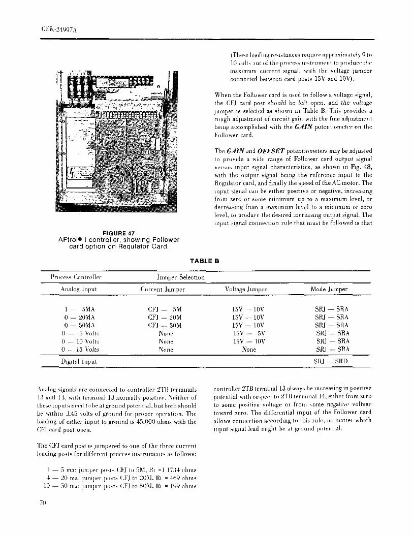
GEK-24997A
(These loading re,,l,,,tances require approximately 9 to10 ,,oil,, mit of tile process ln,,trunlent to produce themax,mum current signal, with the voltage jumperconnected between card posts 15V and 10V).
o
When the Follower card is used to follow a voltage signal,the CFJ card post should be left open, and the voltagejumper is selected as shown in Table B. This provide_ arough adjustment of circuit gain with the fine adjustmentbeing accomplished with the GAIN potentiometer on tileFnllower card.
The GAIN and OFFSET potentiometers may be adjustedto provide a wide range of Follower card output signalversus input signal characteristics, as shown in F_g. 48,with the output signal being the reference input to theRegulator card, and finally the speed of the AC motor. Theinput signal can be e_ther posmve or negative, increasingfi'mn zero or sortie minimum up to a maximum level, ordecreasing from a max_munl level to a mimmum or zerolevel, to produce the desired increasing output signal. Theinput signal connection rule that must be followed rs that
FIGURE 47AFtrol® I controller, showing Follower
card ophon on Requlator Card.
TABLE B
Proces,;Controller ,Jumper Selection
AnalogInput Current Juniper VoltageJumper ModeJumper
l-- 5MA CFJ-- 5M 15V--IOV SRJ--SRA0 -- 20MA CFJ-- 20M 15V_ IOV SRJ-- SRA0 -- 50M4 CFJ-- 50M 15V-- IOV SRJ-- SRA
0 -- 5 Volts None 15V-- 5V SRJ-- SRA0 -- 10Volts None 15V-- iOV SRJ-- SRA0 -- 15 Volts None None SRJ -- SRA
D_g_talInput SRJ-- SRD
5.nalog ,4gnals are connected to controller 2TB terminals controller 2TB ternlmal 13 always be increasing in positive
13 antt 14, w_th terminal 13 normally posmve. Neither of potential with teN,eot to 2TB terminal 14, either from zerot}mse inputs need to bc at ground potelmal, but both should to some positive voltage or from some negative voltagebe w_thln +45 volts of ground for proper operation. The toward zero. The differential input of the Follower cardloading of either input to ground is 45,000 ohm,_ w_th the allows connection according to this rule, no nlatte_ whichCFJcard post open. input signallead rlughtbe at ground potential.
The CFJ card post is jumpered to one of the three currentleading posts for different proces_ instruments aq follows:
1 -- 5 ma: jumper po,t, (:FJ to 5M, RI =1 1734 ohms4 -- 20 ma. jumper p,}st.', (.FJ to 205I. RI : 469 ohms
10 -- 50 ma: jumper po.ts (:FJ to 505I. RI = 190 ohms
7(1

GEK-2 I,t_97.\
I00% MAX(NO jUMPER AT 5¥. tOY 6 t5V)
.JLd
Ld
If)._1 -'
0Z _'
-_ 50% ,..,W
}-
I-
.40_/
0
0 50% i00%I I I
-100% -50% 0
INPUT SIGNAL LEVEL
FIGURE 48AFtrol® I Follower Card, Gain and
Offset Characteristics
71

(;EK-24c)07A
.... OPERATOR'8 STATION
The adiu-ln.'rtt di,e,'tmns of the G.411¥ an,t OFFSETThere are five different models of operator's stations for
lltJhqttl,nileh'rs Il)di'bleve the desired (mil)ut v{'rstl'4 inpul basic drives and drives with jog option, reversing option,chala,qerlst,"_ are s}mwn ill Fig. _t.8,wit}) t}le arrows
reversing with jog option, and follower optnm. Eachii.liealmg the r(,,,uhs of adjustment m the clockwise (CW) operator',,, station model can be ordered in three differentdH'el [lOlls. [n order to ,t('hleve th(' rnaxlnlUnl tlr IninlnlUrll
gains Imxsible, the 5V ,) ISV card po_l,, are jumpered for configuratmns, as denoted by the catalog suffix number:
maxunun! gain, and none of the 5V, 10X,and 15V post,, are A1 -- Remote mounted in own enclosure
jumpered hn minimum gain. The lines ,,hewn m Fig. 48 are KAl -- Kit for user mounting in controller doorrepresentaltve of the different output versus inputcharacteristics which can be achieved bet ween the two limit KFMA1 -- Factory mounted kit in controller door
hnes Aftron I operator's stations are furnished with mounting
Ifa digital (frequency) ,,ignal is to be followed instead of an and wiring instructmns 36A349230AA Sh. 1 & 2 for eitheranalog szgnal, it tsconnected to controlh r 2TB terminals 15 mounting m the controller door (see Fig. 45) or mount,rigand 16, with terminal 1S positive. Terminal 16is connected remote. These operator's stations are listed and describedbelow.through a 1000 t)hm resistor to controller common, which
i_grounded. This digital signal must operate at a frequency Speed Pot, Start PB, Stop PB -- 6VOC71A1, 6VOC7FKA1whn'h is 6 umes the desired motor fre, luency. The signal or 6VOC7IKFMA1drape may be e, hera ,,quare wave or pulse, since only thepn,_fllve going leading edges are used bv the phase-lockedl,op c,lntrol. The pulse magnitude should be 12 volts, +3 This is the standard operator's statmn. It is connected tovohs, and the transmou time should prelerably be les_ than the controller as shown in Fig. 8.It) miero,,ecnnd,_. Signal loading is 10(),000 ohms
Speed Pot., Start PB, Stop PB, Forward-Reverse Switch --6VOC81A1, 6VOC81KA] or 6VOCS1KFMA1
The mode j [1 Il I [ ]{_ 11 [ _ u';ed to selei't whether an analog ordlgmfi reference signal is to be followed As shown m Table
B, connection el card po,,ts SRJ to SR/\ is used for analog Thru operator's station should be used when the6VRllKA 1or 6VRllKFMA1 Reversing P(; card optmn Ignqmts and conne,'t,)n of SRJ to SRD ix used for digital
inpuls. The sig.al i_ then ted through (,ne of a pair of FET added to the controller to provide the motor reversingswitches which art' controlled by Ibe M,mual-Auto selector (selective rotation) function. It zs connected to the_wih'h. controller as shown m Fig. 8.
The MINSP and M,4,hSP potcnlmme, ters{ an he, adju,,ted Speed Pot., Start PB, Sto t) PB, Manual-Auto Switch --6VOC51A 1, 6VOC51KA 1 or 6VOC51KFMA 1.hi ()vezride eilluq an 'malog or digital leferct]ee signal in
,,rder lo set a nllnlmtlnl and nldxl,num ,peed et the motor. This operator's statmn should be used when the 6VFI 1K \ 1Tim range ,}f adju,,tmerlt of the MINSP potentmmeter ishem O tip to ,tp[n'oxnnately 7()'_ oi rated, while the or 6VF11KFMAI Follower PC Card option is added re tho,'I'!A,_;P adjuqment lange ix ftom apl,roxlmately 50% of controller, to provide the capability of following rather anlate,t to over 100' ;, external analog or digital reference signal (Auto selection)
or the Speed potentlometer reference setting (Manual',_eleetmn). It is connected to the controller as shown in Fig.
h should be noted th,Il the oulput of the Follt)we, card i,, 8thc *efts em'e .',lgn,llto Ibc Regulalor card This means IhaI
the ,,ig,ml g,)e,, thrmigh thc Regulator card t.med
,,'e('leratlllll and Ihs eleral,ln cirl nit, and is subject t,i all Speed Pot., Start PB, Stop PB, Run-Jog Switch --6VOCllA1, 6VOCllKA1 or 6VOCllKFMAll.Regulatln card p,,tenllon]eter adlustmentx, except the
Md _,_ and MINN p,lh*ntiometers. This operator's station allows selection of either a Runmode or Jog mode when the Start PB is operated, [t is['he l",)lhlwel ,';n,I al,,i ,'ontain_ an ,.lineal isolator andconnected to the controller as shown in Fig. 8.
,mqlllfvnlg i'm utl wht( h takes the nmh,r freqnene,¢ 4gnalhxn,! lhe I'lcgulahlt card, isolates It, _.nld feed% 11 Ill
Speed Pot , Start PB, Stop PB, Run-Job Switch, Forward-controJh,r 2TIt hq'lnlmll%8 and 0 'l'hi- 'fignal Is a squale Revelse switch -- 6VOC21AI, OVOC21KA1,waw', alh,, hating l,t,tween zel o and 10 x,hs when [()aded t. 6VOC21KFMA1.I,% nulhanlp-,, w.lh h'lminal 8 po,,itix,'. It ts suitable fl,)driving a fre(lneil( % (,_lnlter 1,1 al'enrltleh ' me[u.-,ure nl(}t(ir'
I'_equcn,'_. This operatt,r's xtation eom}fines the Run-J(,b and Forward-Reverse optmnx It rs connected to the controller as shOwriin Fig. 8.
72
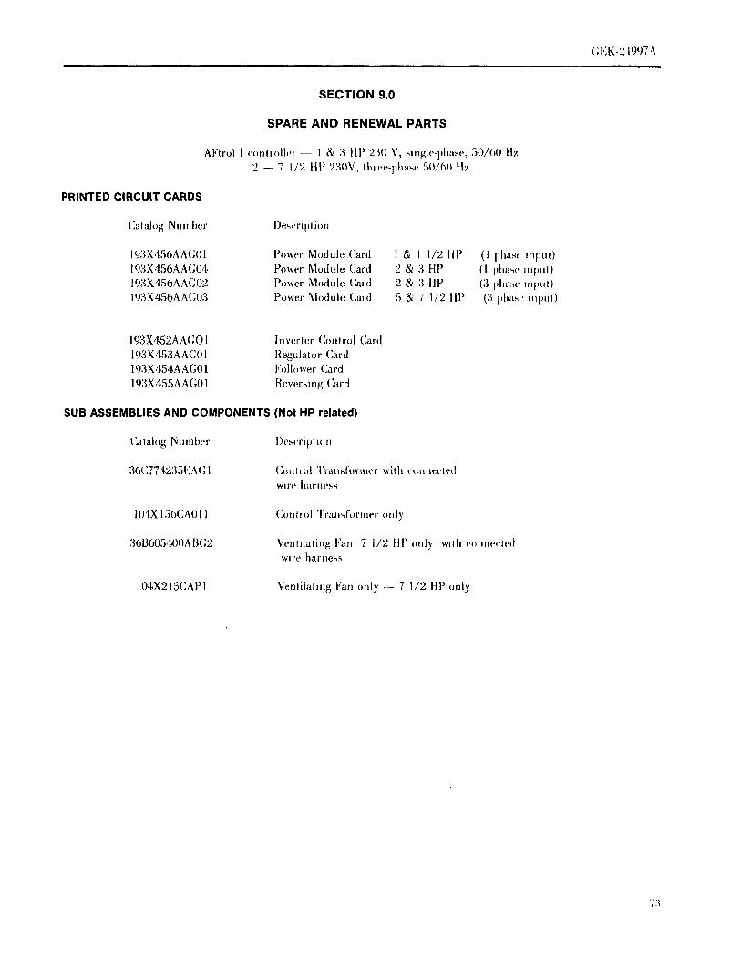
(;EK-219q7 ,\
SECTION 9.0
SPARE AND RENEWAL PARTS
AFtrol I conlroih.i -- I & 3 tip 230 V, .,,ingle-phase, 50/60 !tz
2 -- 7 1/2 lip 230V, three-phase 50160 tlz
PRINTED CIRCUIT CARDS
(]alalog Number l)e_criplion
193X456AA(;OI Power Module Card 1 & I 1/2 lip (1 I)lntsc *nl)ul)193X456AA(;04 Power Module Card 2 & 3 HP (I pha,,c Jupul)
193X456AAG02 Power Module Card 2 & 3 HP (3 i)ha.s(. il:pul)
193X45OAA(;03 Powe,' Module, Card 5 & 7 I/2 lip (3 phase lllptll)
193X452AAGO 1 Inverter (]ont to[ Card
193X453AAG01 Regulator Card193X454AAG01 Follower Card
193X455AAG01 Rever._mg Card
SUB ASSEMBLIES AND COMPONENTS (Not HP related)
(_alalog Number i)cscripl.m
36(_774235EA(; l (kmhol 'i'rausformer with couuecled
wtre harness
lOSX156(ZAOII (]o1111olTl'all'_fOl'llleF()Ill}'
36B605400AB(;2 Vcntdating Fan 7 1/2 ItP only wllh comwch.dWilt _ hal' llc,%s
104X215CAPI Vemilating Fan only -- 7 1/2 HP only
73

SPARE AND RENEWAL PARTS (HP RELATED)
a.j,'ll,d J (i.m_.Jh,r - ]--?, lip 2._0_..bJ._l,, Phw,.. _() ()() II/2 7 I, 2 lip 2;'_()\. I't_[,,,. I'ha,.,,.._){_0 ih,
(()uanhlm_ u,,i II I.'E ,h_v_',lz6,m(h_,m.du.&,[ Drive Rating & Number of Input Phases_t'N.'_II,,_'dEl'._'talhlg)
I 1-1/2 2 3 2 3 5 7 1/2PartName Cat.Number
(1ph) /l j,h) (iL_ (:_l,_,)(_) ('__L_(_:_'__2
\( Ih,w_'l I"u_'_ (17_,\rap) 101,XI094AO05 2 2 3 3
_( I)(m'_'l I"u_('. (;q) \ml)l I()I.XI(I()&M)O5 '2 '2 3 3
Ih,_.l M.duh' :{hD877151EA(;() I I I
I'.w_.l M.d.]h' 3()I)877151EA(;()2 I l
Ih,_.'l M,,.tuh' ?,hl)STT1,51Ell(;() I I I
i'..w,'1%,duh' :{hl)F,TT151E(:(;() 1 1 I
'4( ;l{ ih i,tg_' M.d{d_. Ii) l.\ 1251)( :t)()6 I I '2 2
.",(,1{B_ldg_'Nh,du[_' 10t_\ 1251)(:()07 1 1 2 2
I',_w_,r'h dm,l,q,,_. IO1,\ 170(:B()OO () 6
I',,w(,r 'l'ra,_q(,r _ lO,l.\ 170(:B()O7 _) 6 d 6
I h)w{,r 'l'r,m,.l_,h)[,. l01.\ 170(:B()O8 0 ()
I'Hh', (:h.k_' 1()1.\220A4012 I I '2 2
I' Ill,', ( .h.l,_. l()1\220/\A()1. _, I I 2 2
I',lh', ( ..,p,,,ii.t- I() IX 122't \ L%.% I I 2 '2 I I ') '2
Ti

(;EK-24997A
Bi i t mmrll i ky I IIIII pi I I _ · I IIm_l I
SPARE AND RENEWAL PARTS
AFtrol I controller -- I -- 3 HP 230V, single pha_e, 50/60 Hz2 -- 7 112 HP 230 V, three-phase 50/60 Hz
FIELD MODIFICATION KITS
Catalog Nunlber Description
6VOC71A1 Start, Stop, Speed Adjust, Operator'_ StationRemote Mounted Kit. Has own enclosure.
6VOC71KA1 Start, Stop, Speed Adjust, Operator',', Stahon Kit mount,', in cut ou! of c()ntrollcr d.or.
6VOCIA1 Start, Stop, Forward, Reverse, Speed AdJust Operator's Station lhqnot(, MouiHe,d Kit.tlas own enclosure.
6VOC81 KAl Start, Stop, Forward, Reverse Speed AdJust Operahn"s Shdion Ktl mtmnls in ('ut oul ofcontroller door.
6VOC51AI Start, Stop, Manual, Auto, Speed Adjust Operator's Stamn Remote Mt)unled Kit. IbisOWll enclosure.
6VOC51AK!. Start, Stop, Manual Auto, Speed Adjust Operator',, Statiml Kit mount,, ltl ('ltl UUt o{'controller door.
6VOk;I1A1 Start, Stol), Run, Jog, Speed Adjust Operator's Station Remote Mounted Kit. Ilasown enclosure.
6VOCllKAI Start, Stop, Run, Jog, Speed Adjust Operator's Station Kit mounts in ('ut onlof contoller door.
6VOC21AI Slart, Stop, Forward, Revel'se, Run, Jog, Speed Adiu_t Operator's Statmn Ih,hintedMounted Kit. Has own enclosure.
6VOC2IKA1 Start, Stol), Forward, Re,verse, Run, Jog, Speed Adjust ()peratm'q Sial ton Ktl tilt)trillS
in cut out ot controller door.
6VDS11 KAl Single-Phase, 2 poh' disconnect switch I & I 1/2 HP. Kit mounts itt ('ut out ofcontrollerdoor.
6VDS31KA1 Three-Phase, 3 pole disconnect switch 2 & 7 1/2 tip Kit mounts tn cut out ot c.nttt,lletdoor.
OVARIlKA1 Aux. Run Relay. Includes wire harness. Mount._ in upper light hand corner ot ('ontrolle[using screws already m place.
6VRll KAl Reversing printed cra'mt card assembly*
6VI"II KA1 I".llower i)rinted (.re'uti ca,'d as,,embly*
6VSIlIAI Speed h.licatm' -- Remote tltoutlted
6V lE 11A[ hlsrumeul Enclt)sure -- Remote mmmted
6VFN11KA l (:re)hug ]"tilt Ktl llIOlltll", oil })()[IOlII()t ('ontr(dh'.'
· kil includes snap tit idasm' nmuntmg po,ts
75
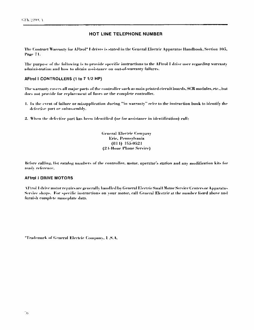
(;I"K :_I'_'_. \
HOT LINE TELEPHONE NUMBER
Thc { ]o.,tra4't Warranty t'or A Ftrol* I drives is stated in the General Electric Apparatus Ilandbook, Section IO5,
t'a_c 7 I.
Thc purpo,c of thc following is to provide specific instructions to the AFlrol ! drive user regarding warrantyadministration and ho_ lo obtain assistance on out-of-warranty failures,
AFtrol I CONTROLLERS (1 to 7 1/2 HP)
Thc warranty co,vcrs all major parts of thc controller such as main printed circuit boards, SCR modules, etc, |}ill
dm,s not provide for reldaecment of fuses or the eomph, te controller.
I. In the ew'nt of failure or misapplication during "in warranty" refer to the instruction book tt) identify the
defective part or sulJassclallly.
2. When thc deb-clive part has been identified (or for assistance in identification) ealh
General Eh. clric (:omlmny
Erie, Pennsylvania
(81 I,) i,55-0521
(2 f-Hour Phone Service)
Ilef_r_, calling, list eatalog numbers of the controller_ motor, operator's station alld any lnodification kits forI'('111J'_ ri,fert'li{'l',
AFtrol I DRIVE MOTORS
SI"trol I driw' moh_r repairs are gcncrail,,, handled l)y General Electric Small Motor Service (]enters or Apl)aratn,,St,rxicc shops. For H.'cific instructions on your motor, {'ali General Electric at the number listed above and
J'urni,,h eomlHCte liamciJla!e data.
*Trademark of ( ;eueral Electric Cmnpan._, J].._l _.

(;EK-2 It)()7,'_
GI,OSSARY OF TERMS
BF1, BF2, BF3 -- Base Frequency Jumpers
CF -- Falter Capacttors
CFJ -- 5M, CFJ-20M, CFJ-50M -- Follower Card milliampere jumpersCLIM -- Current Limit Adjustment1CN, 2CN, 3CN, 4CN, 5CN, 6CN, -- Ribbon Cable Connectors
7CN -- Reversing Card Connector8CN -- 9CN -- Follower Card Connectors
10CN, llCN, 12CN -- Diagnostic Test Point Connect.rsCOM -- Regulator CommonCOMP -- IR Compensation Adjustment
DS -- Disconnect Sw_tch
FC1 -- FC2 -- Follower Card JumpersFILll, FU2, FU3 -- AC Power Fuses
GAIN -- Follower Card Adjustment
KI, K2, K3 -- Power Module Input Power Conaections
1,F -- Filter Choke
LI, L2, L3 -- AC Power ConnectionsILS, 2I,S, 3LS -- Ferrite Core Reactors
LTIM -- Linear Time Adjustment
MAXSP -- Follower Card AdjustmentMAXS -- Maximum Speed Adjustment (Base Frequency)MINF -- Minimum Frequency AdjustmentMINS -- Minimum Speed AdjustmentMINSP -- Follower Card AdjustmentMOV -- Metal Oxide Varistor
N1 -- Negative Converter OutputN2 -- Negative Inverter Input
OFFSET -- Follower Card Adjustment
P1 -- Positive Converter OutputP2 -- Positive Inverter Input
' RC -- Resistor Capacltor Suppressor CircuitRRI -- Auxiliary Relay, N.O. InterlockRR2 -- Auxdiary Relay, CommonRR3 -- Auxd,ary Relay, N.C. InterlockRI IN -- Indicating I,ight
SCI{ --Silicon Controlled Rectifier (Thyristor)
SMN --Speed Meter Negal_w'SMI) -- Speed Mehq Po.,,,l,veSPW, SPX, SPY, SI'Z -- S.ngle Phase JumpersSRA, SRI), SRJ -- Follower Card Mode Jumper,,
77
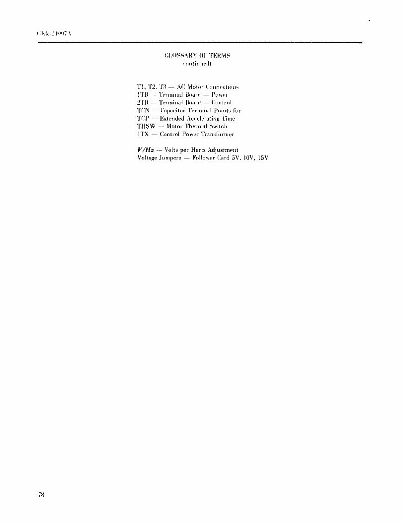
(;I,()SS4RY ()1" 'I'EH M._
w(mlinued)
'Fl, T2, T3 -- A(: Mot(ir (]oIlfleg_llOHSITB --Terminal B-ard -- Powel
2TB -- Tel minal Board -- (]onl_ol
T(]N -- (]apacitor Terminal Points for
'rcP -- Extended Accelerating TimeTHSW -- Motor Thermal Switch
ITX -- Control Power Transformer
V/Hz -- Volts per Hertz Adjustment
Vollage Jumpers -- Follower Card 5V, 10V, 15V
7_

GENERAL ELECTRIC COMPANY
SPEED VARIATOR PRODUCTS OPERATION
ERIE, PENNSYLVANIA 16531
GENERAL_ ELECTRIC,_GEK-,24997A(11/81) 2M (P)