general and vehicle specific installation · general and vehicle specific installation ... xconnect...
TRANSCRIPT
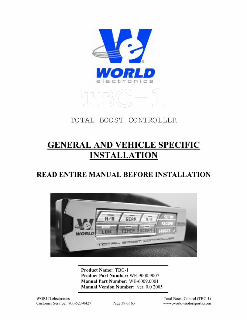
TOTAL BOOST CONTROLLER
GENERAL AND VEHICLE SPECIFIC INSTALLATION
READ ENTIRE MANUAL BEFORE INSTALLATION
Product Name: TBC-1 Product Part Number: WE-9000.9007 Manual Part Number: WE-6009.0001 Manual Version Number: ver. 0.0 2005
WORLD electronics Total Boost Control (TBC-1) Customer Service: 800-523-0427 Page 39 of 63 www.world-motorsports.com
Only use this product for the intended purposes listed in this manual. WORLD electronics is not responsible for any harm or accidents cause by any improper use of this product. Installation of this product should only be performed by an experienced installer. Installation requires many skills, please refer installation to a qualified, experienced installer.
WORLD electronics Total Boost Control (TBC-1) Customer Service: 800-523-0427 Page 40 of 63 www.world-motorsports.com

TBC SAFETY PRECAUTIONS:
! Please read the following safety precautions carefully or severe injury or DEATH can result. ! Please keep this manual in a readily accessible location for future reference.
SAFETY PRECAUTION SYMBOL EXPLANATION: ! The following safety precaution symbols are displayed throughout this manual to represent the following precautions and possible outcome if the precaution is not obeyed.
Danger indicates an imminently hazardous situation which, if not avoided, will result in death or serious injury.
Caution indicates a potentially hazardous situation which, if not avoided, may result in minor or moderate injury.
GENERAL SAFETY PRECAUTIONS:
x Do not install this unit in any way that will affect normal driving visibility or operation of the vehicle. Failure to do so can result in DEATH or serious injury from a traffic accident.
x Do not operate the unit while driving except when learning gears (this must be
done in a vacant parking lot or outdoor track). Failure to do so can result in DEATH or injury from a traffic accident.
x Connect all wiring exactly as shown in the manual. Failure to do so can result in
damage to the unit, the vehicle, or result in DEATH or serious injury to the user. x Connect all the engine compartment components (pressure transducer and
solenoid manifold) exactly as shown in the manual. Failure to do so can cause damage to the unit, the vehicle, or result in DEATH or injury.
x Never disassemble, modify, or tamper with this product or any of its
components. Any modifications or tampering will result in voiding the warranty and can result in damage to the unit, the vehicle or result in DEATH or serious injury to the user.
WORLD electronics Total Boost Control (TBC-1) Customer Service: 800-523-0427 Page 41 of 63 www.world-motorsports.com
GENERAL SAFETY PRECAUTIONS (CONT.): x Do not install this product on a vehicle not listed in this manual. We do not
guarantee product operation on non-listed vehicle applications. However, you may call our customer service hotline to find out if your application has been tested to date.
x This unit is intended for use in a vehicle with a 12VDC operating voltage and a
negative ground system. Connection to any 24VDC or positive ground vehicle can result in damage to the unit or the vehicle.
x Be sure to disconnect the negative terminal of the battery before proceeding with
the installation. Failure to do so can result in vehicle fire, electrical shortage, vehicle or unit damage.
x Do not expose unit to water. Water can cause damage to the unit or vehicle. x Do not operate the touch screen with a sharp object. A sharp object can cause
damage to the touch screen and render the unit useless. x Mount all TBC engine compartment components (pressure transducer and
solenoid manifold) away from excessive heat. Failure to do so can cause damage to the components and render the unit inoperative.
x Route all wiring away from excessive heat. Failure to do so can cause the wire to
melt rendering the unit inoperative. x Do not expose this unit to direct sunlight or excessive heat. Excessive heat can
result in damage to the unit or to the vehicle. x Do not drop this unit or expose it to excessive shock. Excessive shock can result in
damage to the unit or to the vehicle.
WORLD electronics Total Boost Control (TBC-1) Customer Service: 800-523-0427 Page 42 of 63 www.world-motorsports.com
BEFORE INSTALLING THIS PRODUCT:
x Make sure to follow all the vehicle specific instructions carefully or damage to the product can result.
x Make sure that the TBC-1 wire harness does not interfere with any moving parts under
the hood. Failure to do so may result in shorts. x Make sure to follow the vacuum hose connections carefully or serious damage to your
engine could result. x Make sure that you remove the two orange caps and one red cap from the solenoid
manifold before installing. x If your vehicle is not listed in this manual please call our customer service department
for specific instructions for your vehicle. x BEFORE INSTALLING read entire manual and verify that the kit contains all the
parts necessary for installation. See the TBC-1 Parts List table in the back of this manual for the list of materials provided in this kit.
Disconnect the Negative cable of the battery BEFORE proceeding
with installation. Failure to do so may result in severe damage to the unit or the engine. WORLD electronics is NOT responsible for any damages to the engine, vehicle or TBC-1, caused by an installation error.
Installation of this product should only be performed by an
experienced installer. Installation requires many skills, please refer installation to a qualified, experienced installer.
WORLD electronics Total Boost Control (TBC-1) Customer Service: 800-523-0427 Page 43 of 63 www.world-motorsports.com
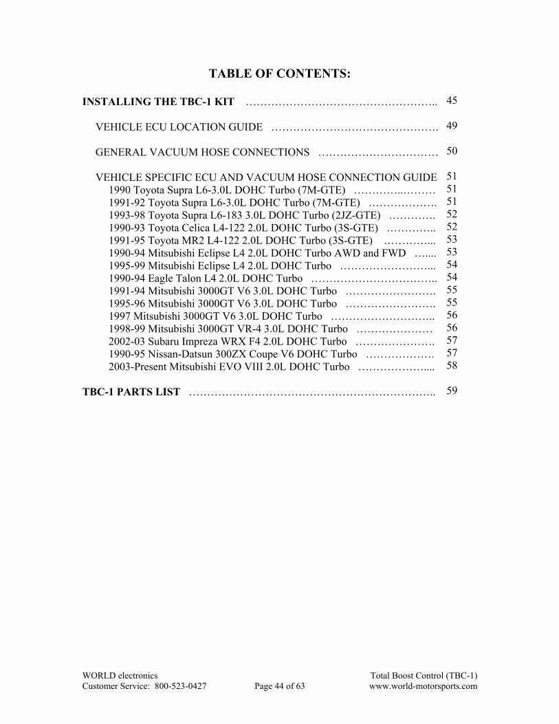
TABLE OF CONTENTS:
INSTALLING THE TBC-1 KIT …………………………………………….. 45 VEHICLE ECU LOCATION GUIDE ………………………………………. 49 GENERAL VACUUM HOSE CONNECTIONS …………………………… 50 VEHICLE SPECIFIC ECU AND VACUUM HOSE CONNECTION GUIDE 51 1990 Toyota Supra L6-3.0L DOHC Turbo (7M-GTE) …………..……… 51 1991-92 Toyota Supra L6-3.0L DOHC Turbo (7M-GTE) ………………. 51 1993-98 Toyota Supra L6-183 3.0L DOHC Turbo (2JZ-GTE) …………. 52 1990-93 Toyota Celica L4-122 2.0L DOHC Turbo (3S-GTE) ………….. 52 1991-95 Toyota MR2 L4-122 2.0L DOHC Turbo (3S-GTE) …………... 53 1990-94 Mitsubishi Eclipse L4 2.0L DOHC Turbo AWD and FWD ….... 53 1995-99 Mitsubishi Eclipse L4 2.0L DOHC Turbo ……………………... 54 1990-94 Eagle Talon L4 2.0L DOHC Turbo …………………………….. 54 1991-94 Mitsubishi 3000GT V6 3.0L DOHC Turbo ……………………. 55 1995-96 Mitsubishi 3000GT V6 3.0L DOHC Turbo ……………………. 55 1997 Mitsubishi 3000GT V6 3.0L DOHC Turbo ……………………….. 56 1998-99 Mitsubishi 3000GT VR-4 3.0L DOHC Turbo ………………… 56 2002-03 Subaru Impreza WRX F4 2.0L DOHC Turbo …………………. 57 1990-95 Nissan-Datsun 300ZX Coupe V6 DOHC Turbo ………………. 57 2003-Present Mitsubishi EVO VIII 2.0L DOHC Turbo ……………….... 58 TBC-1 PARTS LIST ………………………………………………………….. 59
45 49 50 51 51 51 52 52 53 53 54 54 55 55 56 56 57 57 58 59
WORLD electronics Total Boost Control (TBC-1) Customer Service: 800-523-0427 Page 44 of 63 www.world-motorsports.com

INSTALLING THE TBC-1 KIT:
1. Disconnect the Negative cable from the battery. *NOTE: When the negative battery cable is disconnected, you may erase data in your audio or navigation components. Please be sure to write down all security parameters before disconnecting the battery.
2. Locate the ECU (Electronic Control Unit) by looking up your vehicle in the Vehicle
Specific Wiring and Vacuum Hose Connection Guide starting on Page 51 and finding the letter that represents the location in the ECU Location Drawing on Page 49.
3. Locate a suitable location through the firewall to route the wire harness (the hole must
be at least ½” in diameter to accommodate the harness connectors. See the diagram below regarding which wires are routed through the firewall. If an existing hole is not found, then a hole must be drilled through the firewall with a 5/8” drill bit. Use the supplied rubber grommet (part number WE-6000.0009) and route the wires through the grommet and hole.
Make sure that a grommet (existing or supplied) is used when routing the
harness through the firewall or shorts can occur as shown in figure below. Failure to abide by this precaution may cause a potentially hazardous situation which, if not avoided, may result in minor or moderate injury.
WORLD electronics Total Boost Control (TBC-1) Customer Service: 800-523-0427 Page 45 of 63 www.world-motorsports.com

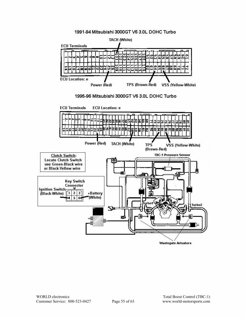
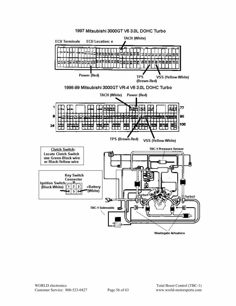
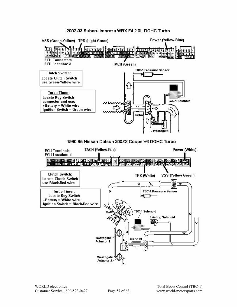
4. Using the Vehicle Specific ECU and Vacuum Hose Connection Guide (see page 51), locate your vehicle model and year. Following the guide, connect the TBC-1 harness to the ECU according to the features desired. *NOTE: you only need to connect the wires that are needed for the features you intend to use. See the chart below to determine the connections that are required to utilize desired features. Refer also to the General Wiring Diagram on the next page.
Features Power GND VSS TACH TPS Clutch
Switch Scramble Switch
Ignition Switch Sense
Turbo Timer Output
Boost/Gear X X X X X Single Boost X X
Scramble X X X Data Recorder X X X X Turbo Timer X X X X
5. Wrap all connections with electrical tape. 6. Mount the Solenoid under the hood, near the wastegate on the firewall or inner
fender. The solenoids are mounted using the solenoid mounting hardware (part
WORLD electronics Total Boost Control (TBC-1) Customer Service: 800-523-0427 Page 46 of 63 www.world-motorsports.com
number WE-6000.0288). If the solenoid is to be mounted on metal, it is recommended to use the supplied rubber washers (part number WE-6000.0125) behind the bracket to dampen noise generated by the solenoid.
When mounting the Solenoid DO NOT block the vent hole. Failure to
abide by this could damage the turbo and/or the engine. 7. Mount the Pressure Sensor under the hood away from high heat but close to the
intake manifold of the engine using the supplied strap bracket (part number WE-6000.0013).
Mount all TBC engine compartment components (pressure sensor and
solenoid) away from excessive heat. Failure to do so can cause damage to the components and render the unit inoperative.
Route all wiring away from excessive heat. Failure to do so can cause
the wire to melt rendering the unit inoperative. 8. Connect the wire harness connectors to the Pressure Sensor and the Solenoid (the
harness connectors are opposite so that the wrong connector cannot be used). Connect the ring tongue terminal from the Pressure Sensor connector to a suitable screw for grounding to the vehicle chassis. (Make sure this is a good ground connection) NOTE: Make sure the connectors go together correctly and “snap” for a good connection.
9. Disconnect the existing vacuum hose/hoses from the wastegate actuator to the
existing wastegate solenoid valve or VSV (Vacuum Switching Valve). Plug up the port going to the wastegate actuator on the existing solenoid valve (see your specific vacuum hose diagram in the Vehicle Specific Wiring and Vacuum Hose Connection Guide).
10. Connect the vacuum hoses to the Solenoid and the Pressure Sensor according the
Vehicle Specific Wiring and Vacuum Hose Connections Guide starting on Page 11. If your vehicle turbo system has been modified (i.e. after-market components added) please see the General Vacuum Hose drawings for single and dual port wastegate types. NOTE: Make sure to place the supplied hose clamps (part number WE-6000.0016) on every vacuum hose connection.
11. Mount TBC-1 in the dashboard utilizing the 5” x ¾” double-faced tape (part number
WE-6000.0018) or the housing mounting bracket (part number WE-6003.0002) supplied with this kit (see the drawing below for instructions on the mounting bracket). NOTE: Before applying two-sided tape, thoroughly clean both surfaces with isopropyl alcohol. The two-sided tape will fully adhere in 24 hours.
WORLD electronics Total Boost Control (TBC-1) Customer Service: 800-523-0427 Page 47 of 63 www.world-motorsports.com
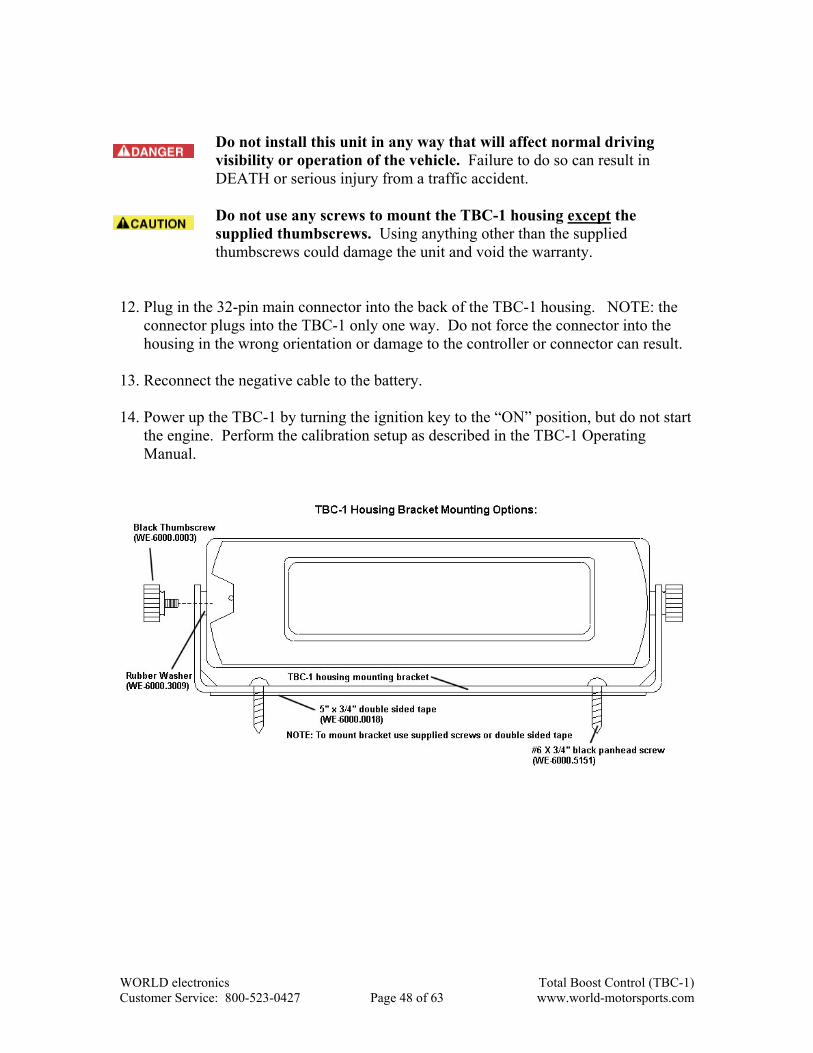
Do not install this unit in any way that will affect normal driving
visibility or operation of the vehicle. Failure to do so can result in DEATH or serious injury from a traffic accident.
Do not use any screws to mount the TBC-1 housing except the
supplied thumbscrews. Using anything other than the supplied thumbscrews could damage the unit and void the warranty.
12. Plug in the 32-pin main connector into the back of the TBC-1 housing. NOTE: the
connector plugs into the TBC-1 only one way. Do not force the connector into the housing in the wrong orientation or damage to the controller or connector can result.
13. Reconnect the negative cable to the battery. 14. Power up the TBC-1 by turning the ignition key to the “ON” position, but do not start
the engine. Perform the calibration setup as described in the TBC-1 Operating Manual.
WORLD electronics Total Boost Control (TBC-1) Customer Service: 800-523-0427 Page 48 of 63 www.world-motorsports.com
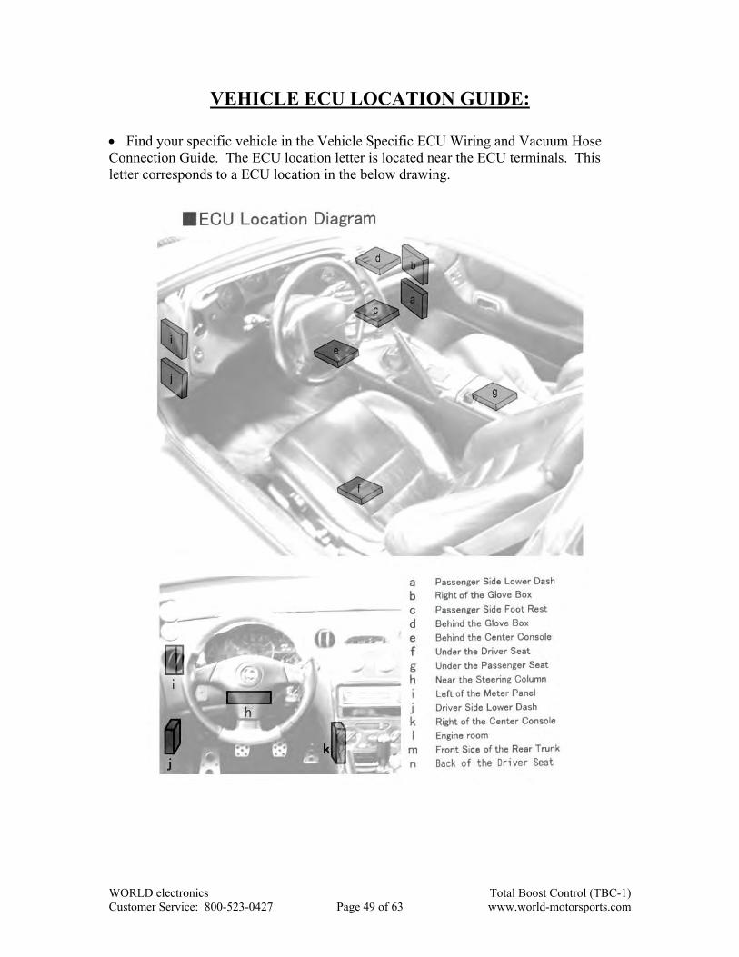
VEHICLE ECU LOCATION GUIDE:
x Find your specific vehicle in the Vehicle Specific ECU Wiring and Vacuum Hose Connection Guide. The ECU location letter is located near the ECU terminals. This letter corresponds to a ECU location in the below drawing.
WORLD electronics Total Boost Control (TBC-1) Customer Service: 800-523-0427 Page 49 of 63 www.world-motorsports.com
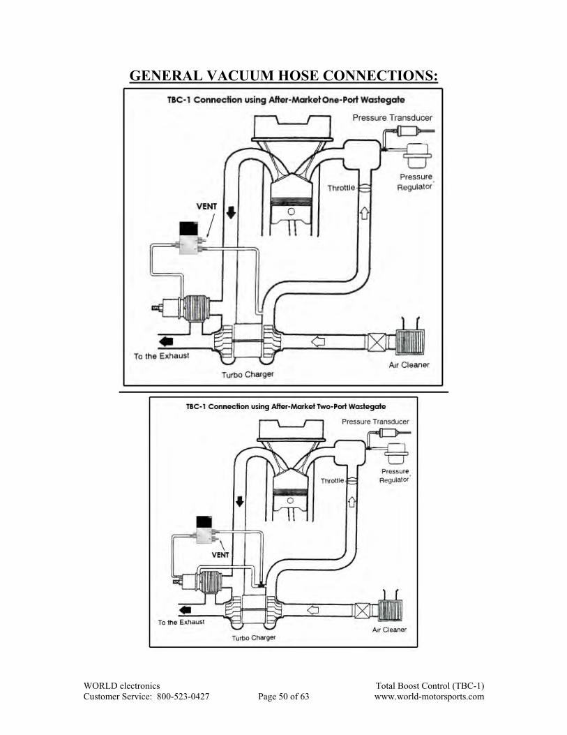
GENERAL VACUUM HOSE CONNECTIONS:
WORLD electronics Total Boost Control (TBC-1) Customer Service: 800-523-0427 Page 50 of 63 www.world-motorsports.com

VEHICLE SPECIFIC ECU AND VACUUM HOSE CONNECTION GUIDE:
WORLD electronics Total Boost Control (TBC-1) Customer Service: 800-523-0427 Page 51 of 63 www.world-motorsports.com

WORLD electronics Total Boost Control (TBC-1) Customer Service: 800-523-0427 Page 52 of 63 www.world-motorsports.com

WORLD electronics Total Boost Control (TBC-1) Customer Service: 800-523-0427 Page 53 of 63 www.world-motorsports.com

WORLD electronics Total Boost Control (TBC-1) Customer Service: 800-523-0427 Page 54 of 63 www.world-motorsports.com
WORLD electronics Total Boost Control (TBC-1) Customer Service: 800-523-0427 Page 55 of 63 www.world-motorsports.com
WORLD electronics Total Boost Control (TBC-1) Customer Service: 800-523-0427 Page 56 of 63 www.world-motorsports.com
WORLD electronics Total Boost Control (TBC-1) Customer Service: 800-523-0427 Page 57 of 63 www.world-motorsports.com
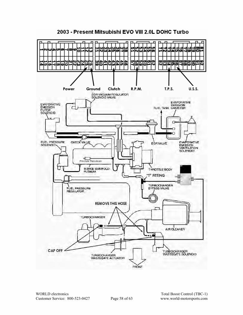
WORLD electronics Total Boost Control (TBC-1) Customer Service: 800-523-0427 Page 58 of 63 www.world-motorsports.com

TBC-1 PARTS LIST:
1 WE-6000.0288 1 WE-9000.9012
Solenoid Valve Bracket TBC-1 Turbo Boost Controller
1 WE-9000.9011 1 WE-2007.2000 Solenoid Valve Assembly Boost pressure sensor
2 WE-6000.0003 1 WE-6003.0002 Black housing bracket thumbscrew TBC-1 housing mounting bracket
WORLD electronics Total Boost Control (TBC-1) Customer Service: 800-523-0427 Page 59 of 63 www.world-motorsports.com

2 WE-6000.0007 1 WE-6000.0008
Brass 1/8” NPT male to 1/8” ID hose Brass ¼” NPT female to 1/8” hose fitting
2 WE-6000.0021 1 WE-6000.0040
Brass 1/8” ID hose “Tee” barb fitting Brass inline 1/8” NPT solenoid air filter
1 WE-6000.0027 10 ft WE-6000.0010
Pressure sensor bracket 1/8” ID black neoprene vacuum hose
WORLD electronics Total Boost Control (TBC-1) Customer Service: 800-523-0427 Page 60 of 63 www.world-motorsports.com
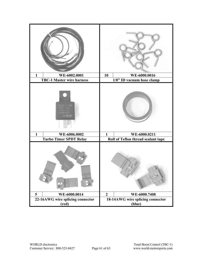
1 WE-6002.0001 10 WE-6000.0016
TBC-1 Master wire harness 1/8” ID vacuum hose clamp
1 WE-6006.0002 1 WE-6000.0211
Turbo Timer SPDT Relay Roll of Teflon thread sealant tape
5 WE-6000.0014 2 WE-6000.7408 22-16AWG wire splicing connector
(red) 18-14AWG wire splicing connector
(blue)
WORLD electronics Total Boost Control (TBC-1) Customer Service: 800-523-0427 Page 61 of 63 www.world-motorsports.com

1 WE-6000.0015 3 WE-6000.3201
16-14AWG female spade crimp connector
12-10AWG female spade crimp connector
2 ft WE-6000.9531 5 WE-6000.0019 14AWG red stranded hook-up wire Black cable wire tie
1 WE-6000.0018 2 WE-6000.0125
5”X3/4” VHB double sided tape #8 screw rubber washer
WORLD electronics Total Boost Control (TBC-1) Customer Service: 800-523-0427 Page 62 of 63 www.world-motorsports.com
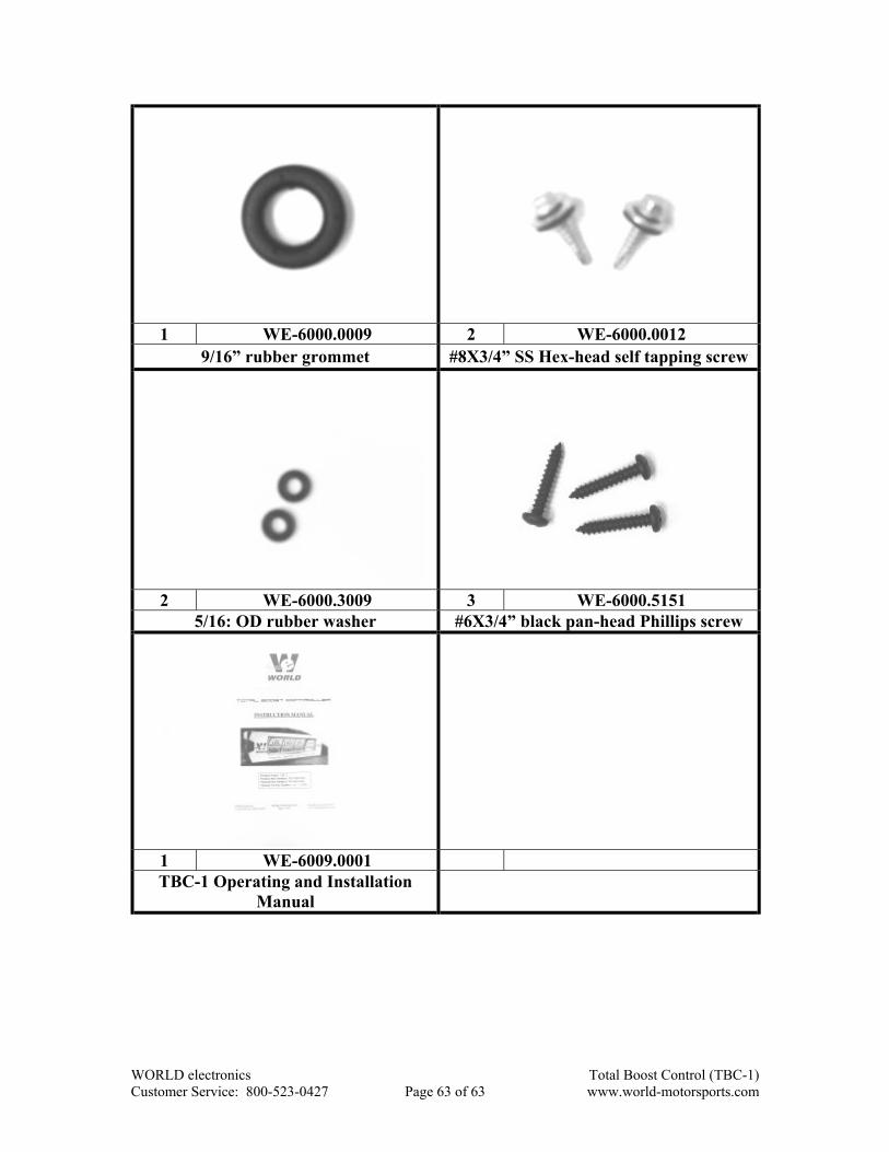
1 WE-6000.0009 2 WE-6000.0012
9/16” rubber grommet #8X3/4” SS Hex-head self tapping screw
2 WE-6000.3009 3 WE-6000.5151
5/16: OD rubber washer #6X3/4” black pan-head Phillips screw
1 WE-6009.0001 TBC-1 Operating and Installation
Manual
WORLD electronics Total Boost Control (TBC-1) Customer Service: 800-523-0427 Page 63 of 63 www.world-motorsports.com