gee336 electronic circuits ii lecture #1 shoubra/electrical... · amplifier feedback concepts ......
TRANSCRIPT
Lecture #1 Course Introduction and Amplifier Feedback Concepts Instructor: Dr. Ahmad El-Banna
Faculty of Engineering Department of Electronics and Communications
Su
mm
er
20
15
GEE336 Electronic Circuits II
© A
hmad
El-B
anna
Agenda
Course Objectives
Course Information
Lectures List
Amplifier Feedback Basics 2
Elec.
Cts I
I, Lec
#1 , S
umm
er 2
015
© A
hmad
El-B
anna
Course Objectives
• By the end of this course, students should be able to:
• Analyze a Feed-Back Amplifier
• Design a Function Generator
• Design Active Filters
• Design ADC and DAC
• Design a Regulated Power Supply
• Implement Simple Projects Using Op-Amps, IC555 , …etc
3
Elec.
Cts I
I, Lec
#1 , S
umm
er 2
015
© A
hmad
El-B
anna
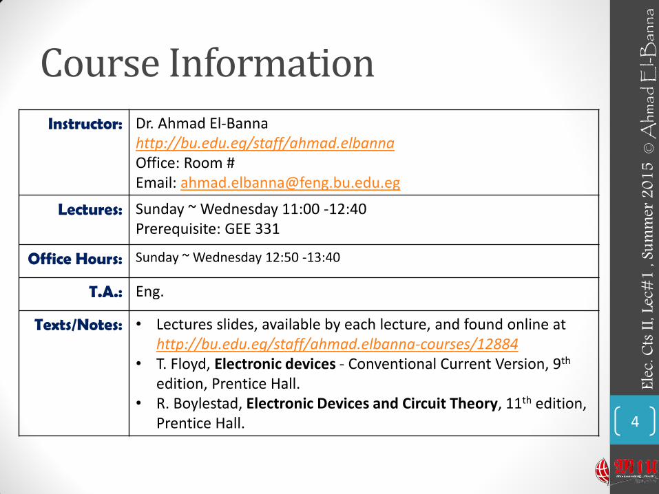
Course Information Instructor: Dr. Ahmad El-Banna
http://bu.edu.eg/staff/ahmad.elbanna Office: Room # Email: [email protected]
Lectures: Sunday ~ Wednesday 11:00 -12:40 Prerequisite: GEE 331
Office Hours: Sunday ~ Wednesday 12:50 -13:40
T.A.: Eng.
Texts/Notes: • Lectures slides, available by each lecture, and found online at http://bu.edu.eg/staff/ahmad.elbanna-courses/12884
• T. Floyd, Electronic devices - Conventional Current Version, 9th edition, Prentice Hall.
• R. Boylestad, Electronic Devices and Circuit Theory, 11th edition, Prentice Hall. 4
Elec.
Cts I
I, Lec
#1 , S
umm
er 2
015
© A
hmad
El-B
anna
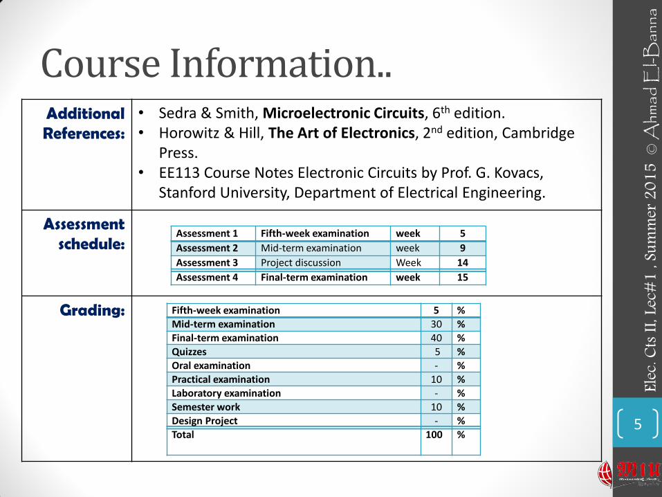
Course Information.. Additional References:
• Sedra & Smith, Microelectronic Circuits, 6th edition. • Horowitz & Hill, The Art of Electronics, 2nd edition, Cambridge
Press. • EE113 Course Notes Electronic Circuits by Prof. G. Kovacs,
Stanford University, Department of Electrical Engineering.
Assessment schedule:
Grading:
5
Fifth-week examination 5 %
Mid-term examination 30 %
Final-term examination 40 %
Quizzes 5 %
Oral examination - %
Practical examination 10 %
Laboratory examination - %
Semester work 10 %
Design Project - %
Total 100 %
Assessment 1 Fifth-week examination week 5
Assessment 2 Mid-term examination week 9
Assessment 3 Project discussion Week 14
Assessment 4 Final-term examination week 15
Elec.
Cts I
I, Lec
#1 , S
umm
er 2
015
© A
hmad
El-B
anna
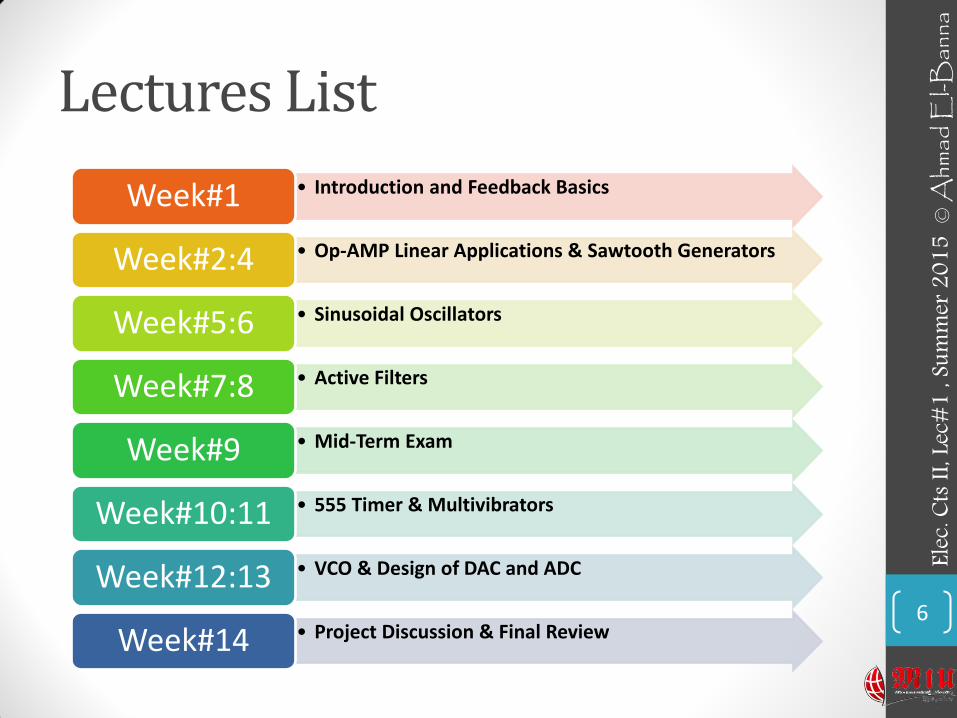
Lectures List
6
• Introduction and Feedback Basics Week#1
• Op-AMP Linear Applications & Sawtooth Generators Week#2:4
• Sinusoidal Oscillators Week#5:6
• Active Filters Week#7:8
• Mid-Term Exam Week#9
• 555 Timer & Multivibrators Week#10:11
• VCO & Design of DAC and ADC Week#12:13
• Project Discussion & Final Review Week#14
Elec.
Cts I
I, Lec
#1 , S
umm
er 2
015
© A
hmad
El-B
anna
FEEDBACK BASICS 7
Elec.
Cts I
I, Lec
#1 , S
umm
er 2
015
© A
hmad
El-B
anna
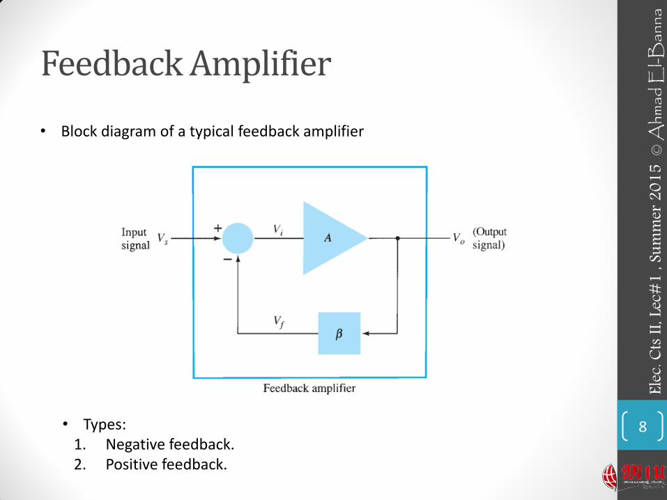
Feedback Amplifier
8
• Block diagram of a typical feedback amplifier
Elec.
Cts I
I, Lec
#1 , S
umm
er 2
015
© A
hmad
El-B
anna
• Types: 1. Negative feedback. 2. Positive feedback.

Feedback Amplifier
• Depending on the relative polarity of the signal being fed back into a circuit, one may have negative or positive feedback.
• Positive feedback drives a circuit into oscillation as in various types of oscillator circuits.
• Negative feedback results in decreased voltage gain, for which a number of circuit features are improved.
• Some improvements of negative feedback are : 1. Higher input impedance. 2. Better stabilized voltage gain. 3. Improved frequency response. 4. Lower output impedance. 5. Reduced noise. 6. More linear operation.
9
Elec.
Cts I
I, Lec
#1 , S
umm
er 2
015
© A
hmad
El-B
anna

FEEDBACK CONNECTION TYPES
10
Elec.
Cts I
I, Lec
#1 , S
umm
er 2
015
© A
hmad
El-B
anna
1. Voltage-series feedback 2. Voltage-shunt feedback
FEEDBACK CONNECTION TYPES..
11
Elec.
Cts I
I, Lec
#1 , S
umm
er 2
015
© A
hmad
El-B
anna
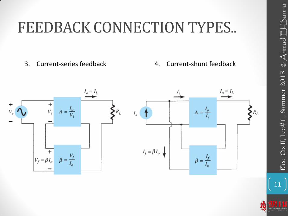
3. Current-series feedback 4. Current-shunt feedback

FEEDBACK CONNECTION TYPES…
• Series feedback connections tend to increase the input resistance, whereas shunt feed-back connections tend to decrease the input resistance.
• Voltage feedback tends to decrease the output impedance, whereas current feedback tends to increase the output impedance.
• We will apply it on Op-Amp circuits.
12
Elec.
Cts I
I, Lec
#1 , S
umm
er 2
015
© A
hmad
El-B
anna

INTRO. TO OP-AMP 13
Elec.
Cts I
I, Lec
#1 , S
umm
er 2
015
© A
hmad
El-B
anna
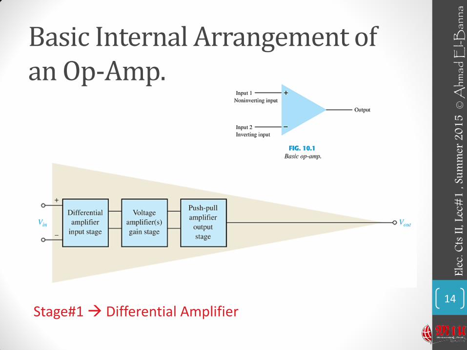
Basic Internal Arrangement of an Op-Amp.
14 Stage#1 Differential Amplifier
Elec.
Cts I
I, Lec
#1 , S
umm
er 2
015
© A
hmad
El-B
anna

Single-Ended Input & Double-Ended (Differential) Input
15
Elec.
Cts I
I, Lec
#1 , S
umm
er 2
015
© A
hmad
El-B
anna
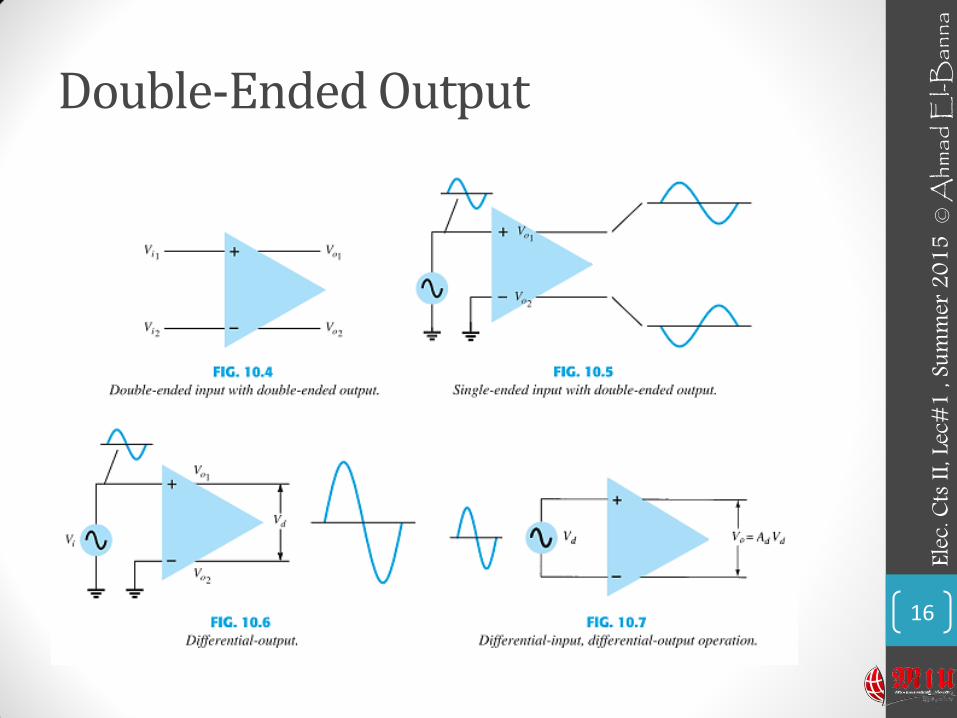
Double-Ended Output
16
Elec.
Cts I
I, Lec
#1 , S
umm
er 2
015
© A
hmad
El-B
anna

Common Mode Operation
17
• Common-Mode Rejection
• Ideally, the two inputs are equally amplified, and since they result in opposite-polarity signals at the output, these signals cancel, resulting in 0-V output.
• Practically, a small output signal will result.
• Noise (any unwanted input signal) is generally common to both inputs, the differential connection tends to provide attenuation of this unwanted input while providing an amplified output of the difference signal applied to the inputs.
• This operating feature is referred to as common-mode rejection .
Elec.
Cts I
I, Lec
#1 , S
umm
er 2
015
© A
hmad
El-B
anna
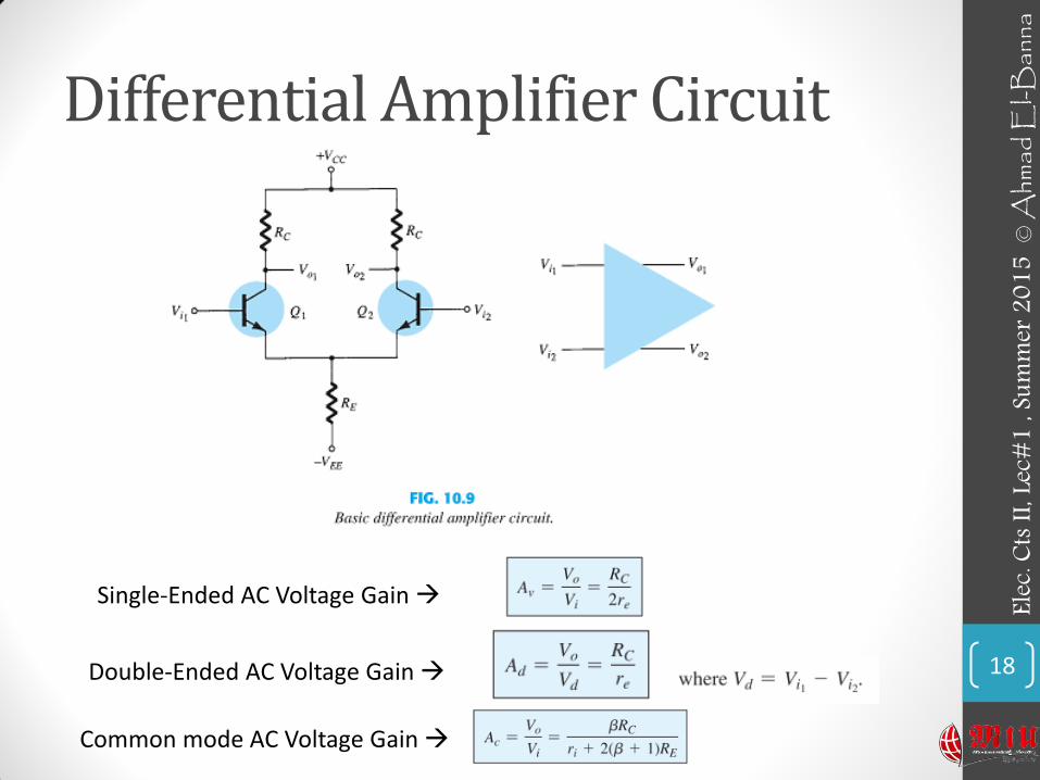
Differential Amplifier Circuit
18
Elec.
Cts I
I, Lec
#1 , S
umm
er 2
015
© A
hmad
El-B
anna
Single-Ended AC Voltage Gain
Double-Ended AC Voltage Gain
Common mode AC Voltage Gain
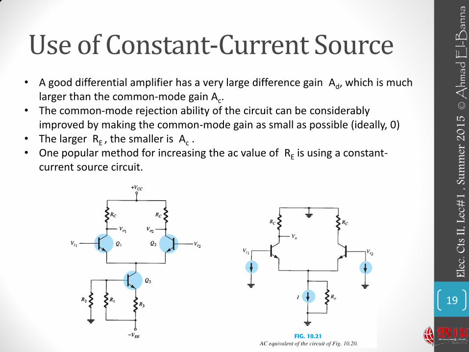
Use of Constant-Current Source
19
• A good differential amplifier has a very large difference gain Ad, which is much larger than the common-mode gain Ac.
• The common-mode rejection ability of the circuit can be considerably improved by making the common-mode gain as small as possible (ideally, 0)
• The larger RE , the smaller is Ac . • One popular method for increasing the ac value of RE is using a constant-
current source circuit.
Elec.
Cts I
I, Lec
#1 , S
umm
er 2
015
© A
hmad
El-B
anna
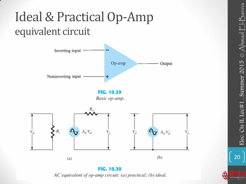
Ideal & Practical Op-Amp equivalent circuit
20
Elec.
Cts I
I, Lec
#1 , S
umm
er 2
015
© A
hmad
El-B
anna
• For more details, refer to:
• Chapter 10,14, R. Boylestad, Electronic Devices and Circuit Theory, 11th edition, Prentice Hall.
• The lecture is available online at:
• http://bu.edu.eg/staff/ahmad.elbanna-courses/12884
• For inquires, send to:
21
Elec.
Cts I
I, Lec
#1 , S
umm
er 2
015
© A
hmad
El-B
anna