ge gas slide-in ranges pgs908 pgs968 · pdf file31-9156 ge gas slide-in ranges pgs908 pgs968...
TRANSCRIPT
GE AppliancesGeneral Electric CompanyLouisville, Kentucky 40225
31-9156
GE Gas Slide-In Ranges
PGS908PGS968PGS975
Technical Service GuideDecember 2007
GE Consumer & Industrial
– 2 –
IMPORTANT SAFETY NOTICEThe information in this service guide is intended for use by individuals possessing adequate backgrounds of electrical, electronic, and mechanical experience. Any attempt to repair a major appliance may result in personal injury and property damage. The manufacturer or seller cannot be responsible for the interpretation of this information, nor can it assume any liability in connection with its use.
WARNING
If the information in this manual is not followed exactly, fi re or explosion may result causing property damage, personal injury or death. If you smell gas:
– Do not try to light any appliance.
– Do not touch any electrical switch; do not use any phone in the building.
– Immediately call the gas supplier from a neighbor’s phone. Follow the gas supplier’s instructions.
– If you cannot reach the gas supplier, call the fi re department.
WARNING
To avoid personal injury, disconnect power before servicing this product. If electrical power is required for diagnosis or test purposes, disconnect the power immediately after performing the necessary checks.
RECONNECT ALL GROUNDING DEVICES
If grounding wires, screws, straps, clips, nuts, or washers used to complete a path to ground are removed for service, they must be returned to their original position and properly fastened.
GE Consumer & IndustrialTechnical Service Guide
Copyright © 2007All rights reserved. This service guide may not be reproduced in whole or in part in any form without written permission from the General Electric Company.
– 3 –
Table of Contents
(Continued next page)
Bake and Broil Burner Flame Adjustments .........................................................................................................42
Bake Burner and Glo-bar Igniter ..............................................................................................................................41
Broil Burner and Glo-bar Igniter ...............................................................................................................................40
Burner Box Removal ........................................................................................................................................................60
Burner Output Ratings ...................................................................................................................................................70
Burner Valves ......................................................................................................................................................................56
Component Locator Views ...........................................................................................................................................25
Control Features ................................................................................................................................................................ 9
Control Panel Assembly ................................................................................................................................................50
Convection Fan Assemblies ........................................................................................................................................44
Convection Fan Cover ...................................................................................................................................................45
Convection Fan Motor ...................................................................................................................................................45
Cooling Fans ......................................................................................................................................................................37
Diagnostics and Service Information .....................................................................................................................66
Door Lock Assembly .......................................................................................................................................................62
Door Switch ........................................................................................................................................................................38
Electronic Range Control (ERC) Pin Locator ..........................................................................................................51
ERC Failure Codes .............................................................................................................................................................72
Fan Cycle Information ....................................................................................................................................................44
Gas Shut-off Valve ............................................................................................................................................................33
Glow-bar Igniter ...............................................................................................................................................................39
Hinge Receiver ..................................................................................................................................................................38
Igniter Switch Assembly ................................................................................................................................................55
Installation ........................................................................................................................................................................... 7
Introduction ......................................................................................................................................................................... 5
Lockout Valve ....................................................................................................................................................................34
Low Flame Simmer Adjustment .................................................................................................................................53
L.P. Conversion Instructions ........................................................................................................................................67

– 4 –
Maintop Burner Alignment ...........................................................................................................................................52
Maintop Burner Assembly Removal ........................................................................................................................59
Maintop Removal ..............................................................................................................................................................58
Manifold ................................................................................................................................................................................58
Meat Probe Outlet ...........................................................................................................................................................46
Motorized Door Lock Circuit Information ..............................................................................................................63
Nomenclature .................................................................................................................................................................... 5
Oven Burner Ignition System ....................................................................................................................................39
Oven Components ..........................................................................................................................................................39
Oven Control Valve .........................................................................................................................................................47
Oven Door Assembly ......................................................................................................................................................30
Oven Door Removal .........................................................................................................................................................29
Oven Light Assemblies ...................................................................................................................................................49
Oven Light Bulbs ..............................................................................................................................................................33
Oven Temperature Sensor ..........................................................................................................................................47
Oven Vent ...........................................................................................................................................................................48
Range Components ........................................................................................................................................................29
Range Removal ..................................................................................................................................................................32
Range Top Components ...............................................................................................................................................52
Rear Cover Removal ........................................................................................................................................................34
Relay Contacts Operation Test and Control Voltage Check .........................................................................71
Schematics and Wiring Diagrams ............................................................................................................................73
Spark Module ......................................................................................................................................................................59
Storage Drawer Removal ..............................................................................................................................................32
Surface Burner Adjustments ......................................................................................................................................52
Surface Burner Igniters ..................................................................................................................................................54
Testing the Flame Stability ...........................................................................................................................................53
Thermal Switches ............................................................................................................................................................61
Touch Panel and ERC ....................................................................................................................................................50
Warranties ...........................................................................................................................................................................79
– 5 –
Introduction
Nomenclature
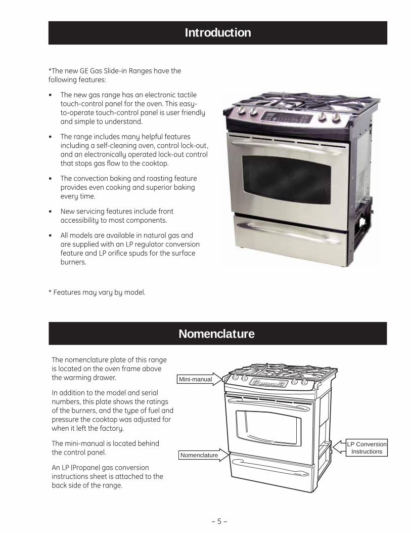
The nomenclature plate of this range is located on the oven frame above the warming drawer.
In addition to the model and serial numbers, this plate shows the ratings of the burners, and the type of fuel and pressure the cooktop was adjusted for when it left the factory.
The mini-manual is located behind the control panel.
An LP (Propane) gas conversion instructions sheet is attached to the back side of the range.
*The new GE Gas Slide-in Ranges have the following features:
The new gas range has an electronic tactile • touch-control panel for the oven. This easy-to-operate touch-control panel is user friendly and simple to understand.
The range includes many helpful features • including a self-cleaning oven, control lock-out, and an electronically operated lock-out control that stops gas fl ow to the cooktop.
The convection baking and roasting feature • provides even cooking and superior baking every time.
New servicing features include front • accessibility to most components.
All models are available in natural gas and • are supplied with an LP regulator conversion feature and LP orifi ce spuds for the surface burners.
* Features may vary by model.
Nomenclature
Mini-manual
LP Conversion Instructions
– 6 –
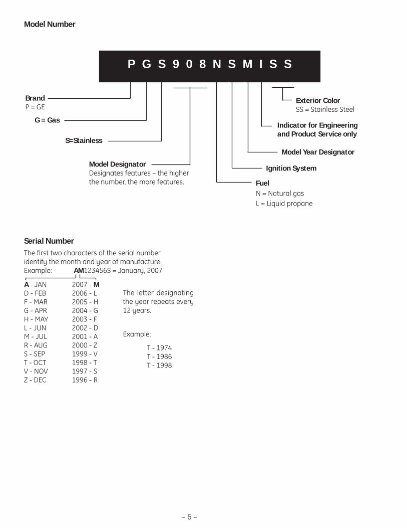
Model DesignatorDesignates features – the higher the number, the more features.
P G S 9 0 8 N S M I S S
BrandP = GE
G = Gas
Exterior Color SS = Stainless Steel
Model Year Designator
Indicator for Engineering and Product Service only
Model Number
Serial NumberThe fi rst two characters of the serial number identify the month and year of manufacture. Example: AM123456S = January, 2007
A - JAN 2007 - M D - FEB 2006 - LF - MAR 2005 - HG - APR 2004 - GH - MAY 2003 - FL - JUN 2002 - DM - JUL 2001 - AR - AUG 2000 - ZS - SEP 1999 - VT - OCT 1998 - TV - NOV 1997 - SZ - DEC 1996 - R
S=Stainless
FuelN = Natural gasL = Liquid propane
Ignition System
The letter des ig nat ing the year re peats every 12 years.
Example:
T - 1974 T - 1986 T - 1998
– 7 –
Installation
(Continued next page)
Installation information is for reference only. See the Installation Instructions shipped with the product for complete details and before attempting to install the range.
Power Supply
This appliance features pilotless electronic ignition for energy savings and reliability. It must be supplied with 120V 60 Hertz, properly grounded dedicated circuit protected by a 15-amp or 20-amp circuit breaker or time delay fuse as noted on the rating plate.
Wiring must conform to the National Electrical Codes.
Grounding Specifi cations
Ground Path Resistance 0.10Ω Max.
Insulation Resistance 250KΩ Min.
Gas Supply
This range is designed to operate at a pressure of 5 inches of water column on natural gas or, if designed for LP gas (propane or butane), 10 inches of water column.
Make sure you are supplying this range with the type of gas for which it is designed.
This range is convertible for use on natural or propane gas. If you are installing this range for use with LP gas, conversion must be made by a qualifi ed LP installer before attempting to operate the range on that gas.
For proper operation, the pressure of natural gas supplied to the regulator must be between 5 inches and 13 inches of water column. For LP gas, the pressure supplied must be between 10 inches and 13 inches of water column.
When checking for proper operation of the regulator, the inlet pressure must be at least 1-inch greater than the operating (manifold) pressure as given above.
The pressure regulator located at the inlet of the range manifold must remain in the supply line regardless of whether natural or LP gas is being used.
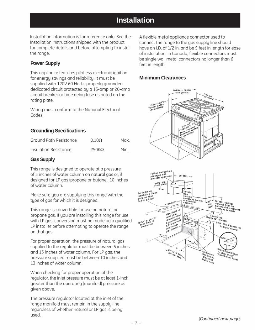
Minimum Clearances
A fl exible metal appliance connector used to connect the range to the gas supply line should have an I.D. of 1/2 in. and be 5 feet in length for ease of installation. In Canada, fl exible connectors must be single wall metal connectors no longer than 6 feet in length.
12″
23-3/16″
7″
AcceptableGas Line &ElectricalOutlet Area
30″ Min.
30″ Min. from cookingsurface to bottomof overhead cabinets
Shave Raised Edge To Clear 31-1/8″ Wide Control Panel
9-1/2″ Min.
From Walls
13″ Max.
depth
For Optimum
Installation These
Surfaces Must
Be Flat & Level
Follow instructions
packaged with
alternate appliance
Countertop Depth 25″ (typical)35-3/4″ to 36-1/2″
from floor to
countertop
18″ Min. vertical distance from the bottom of the adjacentoverhead cabinets
1-1/4″ Min. Counter top to top of drawer
Drawer
cord, plug,
receptacle box
3.5″ to prevent
interference & gas hookup Max. depth of
with drawer
9/16″
29-15/16"Min.30-1/16" Max.
29-15/16″ Min.30-1/16″ Max.
3″
15″

– 8 –
Gas Supply Shutoff Valve
The cooktop itself is not equipped with a gas shut-off valve. If installed correctly, a shutoff valve will be in the main gas supply line “upstream” of the appliance pressure regulator.
WARNING: All ranges can tip causing injury. Install anti-tip device packed with range. The anti-tip device should be attached to the wall.
Anti-Tip Device
Note: Check for proper operation by carefully tipping the range forward.
Standard Installation
If the construction of your cabinet cannot provide a 1/4-in. fl at area at the back of the countertop opening, consider changing the countertop to accommodate this dimension.
Note: A 1-1/2 in. minimum clearance must be maintained between the rear edge of the cooktop and the rear wall above the cooktop.
1/4″ min.flat
9/16″min.flat
29-15/16″–30-1/16″smooth cut
23-3/16″typically
25″typically
Wall
Flat area
R
1/4″
9/16″min.flat
36″Front
Floor
Back
Pressureregulator
Gassupplyline
90° streetelbow
Shut-off valve Flexible gas line
7″ Max.
Rearleveling leg
Wall
FLOOR-CONCRETE
FLOOR-WOOD
Bracketside
Adjacentcabinet
Fig. 1
Top frontedge ofcountertop 25″
Wall plateScrewmust enterwood ormetal
Bracket
Fig. 2

– 9 –
Control Features
Throughout this manual, features and appearance may vary from your model.
How to Light a Gas Surface BurnerPush the control knob in and turn it to the LITE position.
You will hear a clicking noise—the soundof the electric spark igniting the burner.
After the flame lights, turn the knob toadjust the flame size. If the knob stays atLITE, it will continue to click.
When one burner is turned to LITE, all the burners spark. Do not attempt todisassemble or clean around any burnerwhile another burner is on. An electricshock may result, which could cause you to knock over hot cookware.
Push the control knob in and turn itto the LITE position.
Before Lighting a Gas Burner■ Make sure all grates on the range are in
place before using any burner.
■ If your range has the Range Lock-Outfeature, make sure it is disabled beforeattempting to light the surface burners.
After Lighting a Gas Burner■ Do not operate the burner for an
extended period of time withoutcookware on the grate. The finish on the grate may chip without cookware to absorb the heat.
■ Be sure the burners and grates are cool before you place your hand, a pot holder, cleaning cloths or other materials on them.
Sealed Gas BurnersYour gas range cooktop has four sealed gas burners. They offer convenience,cleanability and flexibility to be used in a wide range of cooking applications.
The smallest burner in the right rearposition is the simmer burner. This burnercan be turned to LO for a very low simmersetting. It provides precise cookingperformance for delicate foods such as sauces or foods that require low heat for a long cooking time.
The medium (left rear) and the large (left front) burners are the primaryburners for most cooking. These general-purpose burners can be turned from HI toLO to suit a wide range of cooking needs.
The extra large burner (right front) is the maximum output burner. Like theother three burners, it can be turned from HI to LO for a wide range of cookingapplications; however, this burner isdesigned to quickly bring large amounts of liquid to a boil. It has a special POWERBOIL™ setting designed to be used withcookware 10 inches or larger in diameter.
Medium Small
Large Extra Large
Extra-large burner only
– 10 –
Using the oven controls. (on some models)(Throughout this manual, features and appearance may vary from your model.)

– 11 –
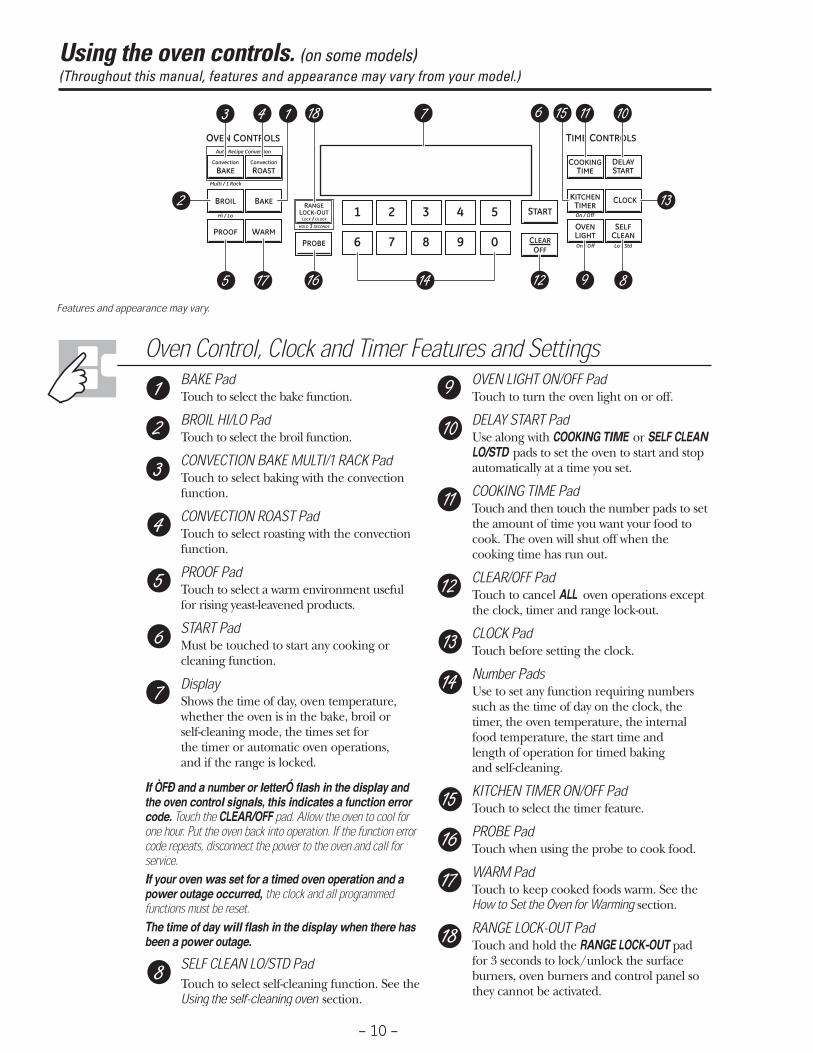
BAKE PadTouch to select the bake function.
BROIL HI/LO PadTouch to select the broil function.
OVEN LIGHT PadTouch to turn the oven light on or off.
SELF CLEAN LO/STD PadTouch to select self-cleaning function. See the Using the self-cleaning oven section.
START PadMust be touched to start any cooking orcleaning function.
Number PadsUse to set any function requiring numberssuch as the time of day on the clock, thetimer, the oven temperature, the internalfood temperature, the start time andlength of operation for timed baking and self-cleaning.
CONTROL LOCK-OUTThe control lock-out is 9 and 0. Touch andhold the 9 and 0 pads at the same time for 3 seconds.
CLEAR/OFF PadTouch to cancel ALL oven operations exceptthe clock, timer and control lock-out.
KITCHEN TIMER ON/OFF PadTouch to select the timer feature.
CLOCK PadTouch before setting the clock.
DELAY START PadUse along with COOKING TIME or SELF CLEANLO/STD pads to set the oven to start and stopautomatically at a time you set.
COOKING TIME PadTouch and then touch the number pads to setthe amount of time you want your food tocook. The oven will shut off when thecooking time has run out.
DisplayShows the time of day, oven temperature,whether the oven is in the bake, broil or self-cleaning mode and the times set for the timer or automatic oven operations.
If “F– and a number or letter” flash in the displayand the oven control signals, this indicates afunction error code. Touch the CLEAR/OFF pad.Allow the oven to cool for one hour. Put the oven backinto operation. If the function error code repeats,disconnect the power to the oven and call for service.
If your oven was set for a timed oven operationand a power outage occurred, the clock and allprogrammed functions must be reset. The time of day will flash in the display whenthere has been a power outage.
Oven Control, Clock and Timer Features and Settings
– 12 –
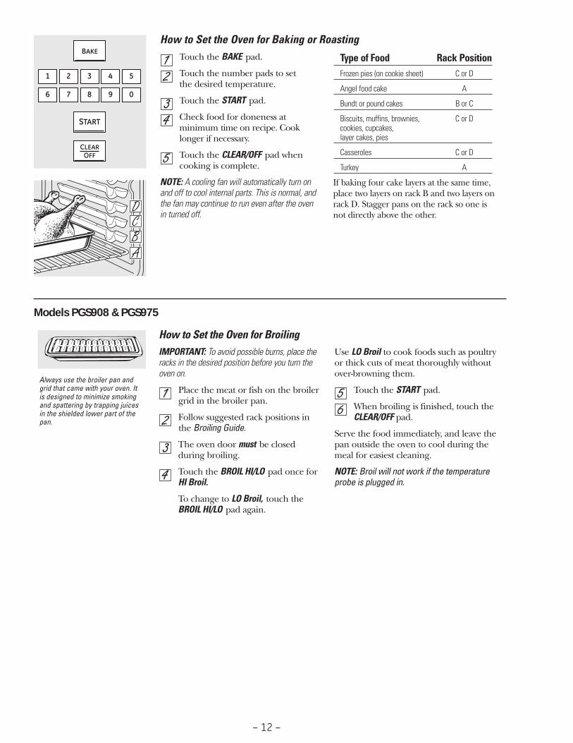
How to Set the Oven for Baking or RoastingTouch the BAKE pad.
Touch the number pads to set the desired temperature.
Touch the START pad.
Check food for doneness atminimum time on recipe. Cooklonger if necessary.
Touch the CLEAR/OFF pad whencooking is complete.
NOTE: A cooling fan will automatically turn onand off to cool internal parts. This is normal, andthe fan may continue to run even after the oven in turned off.
If baking four cake layers at the same time,place two layers on rack B and two layers onrack D. Stagger pans on the rack so one isnot directly above the other.
Type of Food Rack PositionFrozen pies (on cookie sheet) C or D
Angel food cake A
Bundt or pound cakes B or C
Biscuits, muffins, brownies, C or Dcookies, cupcakes, layer cakes, pies
Casseroles C or D
Turkey A
How to Set the Oven for BroilingIMPORTANT: To avoid possible burns, place theracks in the desired position before you turn theoven on.
Place the meat or fish on the broilergrid in the broiler pan.
Follow suggested rack positions inthe Broiling Guide.
The oven door must be closedduring broiling.
Touch the BROIL HI/LO pad once for HI Broil.
To change to LO Broil, touch theBROIL HI/LO pad again.
Use LO Broil to cook foods such as poultry or thick cuts of meat thoroughly withoutover-browning them.
Touch the START pad.
When broiling is finished, touch theCLEAR/OFF pad.
Serve the food immediately, and leave thepan outside the oven to cool during themeal for easiest cleaning.
NOTE: Broil will not work if the temperatureprobe is plugged in.
Always use the broiler pan andgrid that came with your oven. Itis designed to minimize smokingand spattering by trapping juicesin the shielded lower part of thepan.
Models PGS908 & PGS975

– 13 –
To Set the ClockThe clock must be set to the correct timeof day for the automatic oven timingfunctions to work properly. The time ofday cannot be changed during a timedbaking or self-cleaning cycle.
Touch the CLOCK pad.
Touch the number pads.
Touch the START pad.Make sure the clock is set to thecorrect time of day.
To Set the TimerTouch the KITCHEN TIMER ON/OFF pad.
Touch the number pads until theamount of time you want shows in the display. For example, to set 2 hours and 45 minutes, touch 2, 4and 5 in that order. If you make amistake touch the KITCHEN TIMERON/OFF pad and begin again.
Touch the START pad.
After touching the START pad, SET disappears;this tells you the time is counting down, althoughthe display does not change until one minute haspassed. Seconds will not be shown in the displayuntil the last minute is counting down.
When the timer reaches :00, thecontrol will beep 3 times followed by one beep every 6 seconds until the KITCHEN TIMER ON/OFF padis touched.
The 6-second tone can be canceled by followingthe steps in the Special features of your ovencontrol section under Tones at the End of a Timed Cycle.
The timer is a minute timer only. The timer does not control ovenoperations. The maximum setting onthe timer is 9 hours and 59 minutes.
To Reset the TimerIf the display is still showing the timeremaining, you may change it bytouching the KITCHEN TIMER ON/OFF pad,then touch the number pads until thetime you want appears in the display.
If the remaining time is not in the display(clock, delay start or cooking time are inthe display), recall the remaining time bytouching the KITCHEN TIMER ON/OFF padand then touching the number pads toenter the new time you want.
To Cancel the TimerTouch the KITCHEN TIMER ON/OFFpad twice.
Your control will allow you to lock out the surfaceburners, oven burners and control panel so theycannot be activated.
To lock/unlock the controls:
Turn all surface burners off.
Touch and hold the RANGELOCK-OUT pad for 3 seconds untilthe display shows LOC ON.
To unlock the control, touch andhold the RANGE LOCK-OUT pad for 3 seconds until the display shows LOC OFF.
When this feature is on and the touchpads are touched, the control will beepand the display will show LOC ON.
■ The control lock-out mode affects all controls.No controls will work when this feature isactivated.
■ The adjustment will be retained in memoryafter a power failure.
Range Lock-Out (on some models)
– 14 –
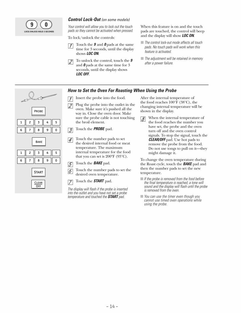
Your control will allow you to lock out the touchpads so they cannot be activated when pressed.
To lock/unlock the controls:
Touch the 9 and 0 pads at the sametime for 3 seconds, until the displayshows LOC ON.
To unlock the control, touch the 9and 0 pads at the same time for 3seconds, until the display shows LOC OFF.
When this feature is on and the touchpads are touched, the control will beepand the display will show LOC ON.
■ The control lock-out mode affects all touchpads. No touch pads will work when thisfeature is activated.
■ The adjustment will be retained in memoryafter a power failure.
Control Lock-Out (on some models)
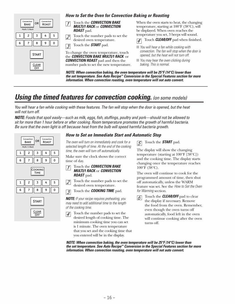
Insert the probe into the food.
Plug the probe into the outlet in theoven. Make sure it’s pushed all the way in. Close the oven door. Makesure the probe cable is not touchingthe broil element.
Touch the PROBE pad.
Touch the number pads to set the desired internal food or meattemperature. The maximuminternal temperature for the foodthat you can set is 200ºF (93°C).
Touch the BAKE pad.
Touch the number pads to set thedesired oven temperature.
Touch the START pad.
The display will flash if the probe is inserted into the outlet and you have not set a probetemperature and touched the START pad.
After the internal temperature of the food reaches 100°F (38°C), thechanging internal temperature will beshown in the display.
When the internal temperature ofthe food reaches the number youhave set, the probe and the oventurn off and the oven controlsignals. To stop the signal, touch theCLEAR/OFF pad. Use hot pads toremove the probe from the food. Do not use tongs to pull on it—theymight damage it.
To change the oven temperature duringthe Roast cycle, touch the BAKE pad andthen the number pads to set the newtemperature.
■ If the probe is removed from the food beforethe final temperature is reached, a tone willsound and the display will flash until the probeis removed from the oven.
■ You can use the timer even though youcannot use timed oven operations whileusing the probe. 19
How to Set the Oven For Roasting When Using the Probe

– 15 –
Using the timed baking and roasting features. (on some models)
NOTE: Foods that spoil easily—such as milk, eggs, fish, stuffings, poultry and pork—should not be allowed to sit formore than 1 hour before or after cooking. Room temperature promotes the growth of harmful bacteria. Be sure thatthe oven light is off because heat from the bulb will speed harmful bacteria growth.
How to Set an Immediate Start and Automatic StopThe oven will turn on immediately and cook for a selected length of time. At the end of thecooking time the oven will turn off automatically.
Touch the BAKE pad.
Using the number pads, enter thedesired temperature.
Touch the COOKING TIME pad.
NOTE: If your recipe requires preheating, youmay need to add additional time to the length ofthe cooking time.
Using the number pads, enter thedesired baking time. The oventemperature and the cooking timethat you entered will be displayed.
Touch the START pad.
The display will show the changingtemperature (starting at 100ºF [38ºC])and the cooking time. The display startschanging once the temperature reaches100ºF (38ºC).
The oven will continue to cook for theprogrammed amount of time, then shutoff automatically, unless the WARMfeature was set. See the How to Set the Ovenfor Warming section.
Touch the CLEAR/OFF pad to clearthe display.
How to Set a Delayed Start and Automatic StopYou can set the oven control to delay-start theoven, cook for a specific length of time and thenturn off automatically.
Make sure the clock shows the correcttime of day.
Touch the BAKE pad.
Using the number pads, enter thedesired temperature.
Touch the COOKING TIME pad.
NOTE: If your recipe requires preheating, youmay need to add additional time to the length ofthe cooking time.
Using the number pads, enter thedesired baking time.
Touch the DELAY START pad.
Using the number pads, enter thetime of day you want the oven toturn on and start cooking.
Touch the START pad.
NOTE: An attention tone will sound if you areusing timed baking and do not touch the STARTpad after entering the baking temperature.
If you would like to check the times youhave set, touch the DELAY START pad tocheck the start time you have set or touch the COOKING TIME pad to check thelength of cooking time you have set.
When the oven turns on at the time ofday you have set, the display will show thechanging temperature (starting at 100ºF[38ºC]) and the cooking itme. Thedisplay starts changing once thetemperature reaches 100ºF (38ºC).
The oven will continue to cook for theprogrammed amount of time, then shutoff automatically, unless the WARMfeature was set. See the How to Set the Ovenfor Warming section.
Touch the CLEAR/OFF pad to clearthe display.
– 16 –
Touch the CONVECTION BAKEMULTI/1 RACK or CONVECTIONROAST pad.Touch the number pads to set thedesired oven temperature.Touch the START pad.
To change the oven temperature, touchthe CONVECTION BAKE MULTI/1 RACK orCONVECTION ROAST pad and then thenumber pads to set the new temperature.
When the oven starts to heat, the changingtemperature, starting at 100°F (38°C), willbe displayed. When oven reaches thetemperature you set, 3 beeps will sound.
Touch CLEAR/OFF pad when finished.
■ You will hear a fan while cooking withconvection. The fan will stop when the door isopened, but the heat will not turn off.
■ You may hear the oven clicking during baking. This is normal.
How to Set the Oven for Convection Baking or Roasting
OR
NOTE: When convection baking, the oven temperature will be 25°F (14°C) lower than the set temperature. See Auto Recipe™ Conversion in the Special Features section for moreinformation. When convection roasting, oven temperature will not auto convert.
Using the timed features for convection cooking. (on some models)
You will hear a fan while cooking with these features. The fan will stop when the door is opened, but the heat will not turn off.NOTE: Foods that spoil easily—such as milk, eggs, fish, stuffings, poultry and pork—should not be allowed to sit for more than 1 hour before or after cooking. Room temperature promotes the growth of harmful bacteria. Be sure that the oven light is off because heat from the bulb will speed harmful bacteria growth.
How to Set an Immediate Start and Automatic StopThe oven will turn on immediately and cook for aselected length of time. At the end of the cookingtime, the oven will turn off automatically.Make sure the clock shows the correcttime of day.
Touch the CONVECTION BAKEMULTI/1 RACK or CONVECTIONROAST pad.Touch the number pads to set thedesired oven temperature.Touch the COOKING TIME pad.
NOTE: If your recipe requires preheating, youmay need to add additional time to the length of the cooking time.
Touch the number pads to set thedesired length of cooking time. Theminimum cooking time you can set is 1 minute. The oven temperaturethat you set and the cooking time thatyou entered will be in the display.
Touch the START pad.
The display will show the changingtemperature (starting at 100°F [38°C]) and the cooking time. The display startschanging once the temperature reaches100°F (38°C).The oven will continue to cook for theprogrammed amount of time, then shut off automatically, unless the WARMfeature was set. See the How to Set the Ovenfor Warming section.
Touch the CLEAR/OFF pad to clear the display if necessary. Remove the food from the oven. Remember,even though the oven turns offautomatically, food left in the oven will continue cooking after the oventurns off.
OR
NOTE: When convection baking, the oven temperature will be 25°F (14°C) lower than the set temperature. See Auto Recipe™ Conversion in the Special Features section for moreinformation. When convection roasting, oven temperature will not auto convert.

– 17 –
How to Set a Delayed Start and Automatic StopYou can set the oven control to delay-start theoven, cook for a specific length of time and thenturn off automatically.Make sure the clock shows the correcttime of day.
Touch the CONVECTION BAKEMULTI/1 RACK or CONVECTIONROAST pad.Touch the number pads to set thedesired oven temperature.Touch the COOKING TIME pad.
NOTE: If your recipe requires preheating, youmay need to add additional time to the length ofthe cooking time.
Touch the number pads to set thedesired cooking time.Touch the DELAY START pad.
Touch the number pads to set thetime of day you want the oven toturn on and start cooking.
If you would like to check the times you have set,touch the DELAY START pad to check the start timeyou have set, or touch the COOKING TIME pad tocheck the length of cooking time you have set.
Touch the START pad.
NOTE: An attention tone will sound if you are using timed baking or roasting and do not touch the START pad after entering the baking or roasting temperature.When the oven turns on at the time of day you have set, the display will show the changing temperature (starting at 100°F [38°C]) and thecooking time. The display starts changingonce the temperature reaches 100°F(38°C).The oven will continue to cook for theprogrammed amount of time, then shut off automatically, unless the WARMfeature was set. See the How to Set the Ovenfor Warming section.
Touch the CLEAR/OFF pad to clear the display if necessary. Remove the food from the oven. Remember,even though the oven shuts offautomatically, food left in the oven will continue cooking after the oventurns off.
OR
NOTE: When convection baking, the oven temperature will be 25°F (14°C) lower than the set temperature. See Auto Recipe™ Conversion in the Special Features section for moreinformation. When convection roasting, oven temperature will not auto convert.
Using the convection oven. (on some models)
How to Set the Oven for Convection Roasting when Using the ProbeThe display will flash PROBE and theoven control will signal if the probe isinserted into the outlet, and you have notset a probe temperature and pressed theSTART pad.
Place the oven rack in the positionthat centers the food between thetop and bottom of the oven. Insertthe probe into the meat.Plug the probe into the outlet in theoven. Make sure it is pushed all theway in. Close the oven door.Touch the CONVECTION ROAST pad.
Touch the number pads to set thedesired oven temperature.Touch the PROBE pad.
Touch the number pads to set thedesired internal meat temperature.Touch the START pad.
When the oven starts to heat, the wordLO will be in the display.After the internal temperature of the meatreaches 100°F (38°C), the changing internaltemperature will be shown in the display.
When the internal temperature ofthe meat reaches the number youhave set, the probe and the oventurn off and the oven controlsignals. To stop the signal, touch theCLEAR/OFF pad. Use hot pads toremove the probe from the food.Do not use tongs to pull on it—theymight damage it.
CAUTION: To prevent possible burns,do not unplug the probe from the oven outlet untilthe oven has cooled. Do not store the probe in the oven.
NOTE:
■ If the probe is removed from the food beforethe final temperature is reached, a tone willsound and the display will flash until the probeis removed from the oven.
■ You will hear a fan while cooking with thisfeature. The fan will stop when the door isopened, but the heat will not turn off.
■ You can use the kitchen timer even though youcannot use timed oven operations.
For best results when roasting largeturkeys and roasts, we recommendusing the probe included in theconvection oven.
Convection Roasting GuideTo change the oven temperature during the Convection Roast cycle, touch the CONVECTION ROAST pad and then touch the number pads to set the new desired temperature.
– 18 –
The proofing feature maintains a warm environment useful for rising yeast-leavened products.
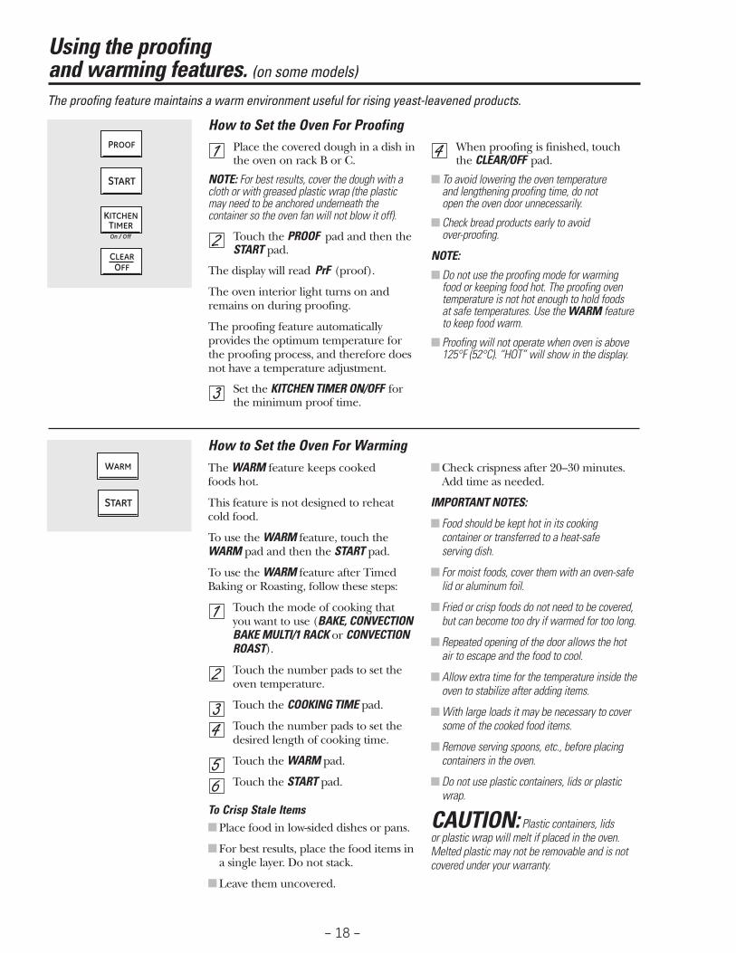
How to Set the Oven For ProofingPlace the covered dough in a dish inthe oven on rack B or C.
NOTE: For best results, cover the dough with acloth or with greased plastic wrap (the plasticmay need to be anchored underneath thecontainer so the oven fan will not blow it off).
Touch the PROOF pad and then the START pad.
The display will read PrF (proof).
The oven interior light turns on andremains on during proofing.
The proofing feature automaticallyprovides the optimum temperature forthe proofing process, and therefore doesnot have a temperature adjustment.
Set the KITCHEN TIMER ON/OFF forthe minimum proof time.
When proofing is finished, touch the CLEAR/OFF pad.
■ To avoid lowering the oven temperature and lengthening proofing time, do not open the oven door unnecessarily.
■ Check bread products early to avoid over-proofing.
NOTE:
■ Do not use the proofing mode for warming food or keeping food hot. The proofing oventemperature is not hot enough to hold foods at safe temperatures. Use the WARM featureto keep food warm.
■ Proofing will not operate when oven is above125°F (52°C). “HOT” will show in the display.
How to Set the Oven For WarmingThe WARM feature keeps cooked foods hot.
This feature is not designed to reheatcold food.
To use the WARM feature, touch theWARM pad and then the START pad.
To use the WARM feature after TimedBaking or Roasting, follow these steps:
Touch the mode of cooking that you want to use (BAKE, CONVECTIONBAKE MULTI/1 RACK or CONVECTIONROAST).
Touch the number pads to set theoven temperature.
Touch the COOKING TIME pad.
Touch the number pads to set thedesired length of cooking time.
Touch the WARM pad.
Touch the START pad.
To Crisp Stale Items■ Place food in low-sided dishes or pans.
■ For best results, place the food items ina single layer. Do not stack.
■ Leave them uncovered.
■ Check crispness after 20–30 minutes. Add time as needed.
IMPORTANT NOTES:
■ Food should be kept hot in its cookingcontainer or transferred to a heat-safe serving dish.
■ For moist foods, cover them with an oven-safelid or aluminum foil.
■ Fried or crisp foods do not need to be covered,but can become too dry if warmed for too long.
■ Repeated opening of the door allows the hotair to escape and the food to cool.
■ Allow extra time for the temperature inside theoven to stabilize after adding items.
■ With large loads it may be necessary to coversome of the cooked food items.
■ Remove serving spoons, etc., before placingcontainers in the oven.
■ Do not use plastic containers, lids or plasticwrap.
CAUTION: Plastic containers, lids or plastic wrap will melt if placed in the oven.Melted plastic may not be removable and is notcovered under your warranty.
25
Using the proofing ge.com (U.S.)and warming features. (on some models) www.GEAppliances.ca (Canada)

– 19 –
Adjust the oven thermostat—Do it yourself!You may find that your new oven cooks differently than the one it replaced. Use your new oven for a few weeks tobecome more familiar with it. If you still think your new oven is too hot or too cold, you can adjust the thermostatyourself.
Do not use thermometers, such as those found in grocery stores, to check the temperature setting of your oven.These thermometers may vary 20–40 degrees F (11–22 degrees C).
NOTE: This adjustment will only affect baking, convection baking (on some models) and convection roasting (on some models) temperatures; it will not affect broiling or self-cleaning temperatures. The adjustment will beretained in memory after a power failure.
To Adjust the ThermostatTouch the BROIL HI/LO and BAKEpads at the same time for 3 secondsuntil the display shows SF.
Touch the BAKE pad. A two-digitnumber shows in the display.
Touch BAKE again to alternatebetween increasing and decreasingthe oven temperature.
The oven temperature can beadjusted up to (+) 35ºF (19°C)hotter or (-) 35ºF (19°C) cooler.Touch the number pads the sameway you read them. For example, tochange the oven temperature 15ºF(8°C), touch 1 and 5.
When you have made theadjustment, touch the START pad togo back to the time of day display.Use your oven as you wouldnormally.
+
How to Set the Oven for CleaningTurn all of the surface burners off.
Touch the SELF CLEAN LO/STD padonce for a 4-hour (3-hour on somemodels) clean time or twice for a 3-hour (4-hour on some models)clean time.A 3-hour self-clean time isrecommended for use whencleaning small, contained spills. Aself-clean time of 4 hours or longeris recommended for a dirtier oven.If a time other than 4 hours or 3 hours is needed, use the numberpads and enter the desired cleantime.
You can change the clean time to anytime between 3 hours (21⁄2 hours on somemodels) and 5 hours, depending on howdirty your oven is.
Touch the START pad.
The door locks automatically. The displaywill show the clean time remaining. It willnot be possible to open the oven door until the temperature drops below the lock temperature and the LOCKED lightgoes off.
When the LOCKED light goes off, you willbe able to open the door.
On models with Range Lock-Out,touch and hold the RANGE LOCK-OUT pad for 3 seconds to turn it off.
■ The word LOCKED will flash and theoven control will signal if you set theclean cycle and forget to close the oven door.
■ To stop a clean cycle, touch theCLEAR/OFF pad. When the LOCKED lightgoes off indicating the oven has cooledbelow the locking temperature, youwill be able to open the door.
Using the self-cleaning oven.
– 20 –
The oven door must be closed and all controls must be set correctly for the cycle to work properly.
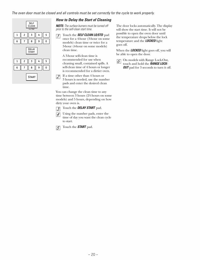
How to Delay the Start of CleaningNOTE: The surface burners must be turned offprior to the self-clean start time.
Touch the SELF CLEAN LO/STD padonce for a 4-hour (3-hour on somemodels) clean time or twice for a 3-hour (4-hour on some models)clean time.
A 3-hour self-clean time isrecommended for use whencleaning small, contained spills. Aself-clean time of 4 hours or longeris recommended for a dirtier oven.If a time other than 4 hours or 3 hours is needed, use the numberpads and enter the desired cleantime.
You can change the clean time to anytime between 3 hours (21⁄2 hours on somemodels) and 5 hours, depending on howdirty your oven is.
Touch the DELAY START pad.
Using the number pads, enter thetime of day you want the clean cycleto start.
Touch the START pad.
The door locks automatically. The displaywill show the start time. It will not bepossible to open the oven door until the temperature drops below the locktemperature and the LOCKED light goes off.
When the LOCKED light goes off, you willbe able to open the door.
On models with Range Lock-Out,touch and hold the RANGE LOCK-OUT pad for 3 seconds to turn it off.

– 21 –
Your new touch pad control has additional features that you may choose to use. The following are the features and how you may activate them.
The special feature modes can only be activated while the display is showing the time of day. They remain in the control’s memory until the steps are repeated.
When the display shows your choice, touch the START pad. The special features will remain in memory after a power failure, except for the Sabbath feature, which will have to be reset.
12-Hour ShutdownWith this feature, should you forget and leave theoven on, the control will automatically turn off theoven after 12 hours during baking functions orafter 3 hours during a broil function.
If you wish to turn OFF this feature, followthe steps below.
Touch the BROIL HI/LO and BAKEpads at the same time for 3 secondsuntil the display shows SF.
Touch the DELAY START pad untilno shdn (no shut-off) appears in thedisplay.
Touch the START pad to activate theno shut-off and leave the control set in this special features mode.
+
Fahrenheit or Celsius Temperature SelectionYour oven control is set to use the Fahrenheittemperature selections, but you may change thisto use the Celsius selections.
Touch the BROIL HI/LO and BAKEpads at the same time for 3 secondsuntil the display shows SF.
Touch the COOKING TIME and BROILHI/LO pads at the same time. Thedisplay will show F (Fahrenheit).
Touch the COOKING TIME and BROILHI/LO pads again at the same time.The display will show C (Celsius).
Touch the START pad.
+
+
Tones at the End of a Timed CycleAt the end of a timed cycle, 3 short beeps willsound followed by one beep every 6 seconds until the CLEAR/OFF pad is touched. Thiscontinual 6-second beep may be canceled.
To cancel the 6-second beep:
Touch the BROIL HI/LO and BAKEpads at the same time for 3 secondsuntil the display shows SF.
Touch the KITCHEN TIMER ON/OFFpad. The display shows CON BEEP(continuous beep). Touch theKITCHEN TIMER ON/OFF pad again. The display shows BEEP.(This cancels the one beep every 6 seconds.)
Touch the START pad.
+
ge.com (U.S.) Special features of your oven control. www.GEAppliances.ca (Canada)

– 22 –
12-Hour, 24-Hour or Clock BlackoutYour control is set to use a 12-hour clock.
If you would prefer to have a 24-hourmilitary time clock or black out the clockdisplay, follow the steps below.
Touch the BROIL HI/LO and BAKEpads at the same time for 3 secondsuntil the display shows SF.
Touch the CLOCK pad once. Thedisplay will show 12 hr. If this is the choice you want, touch the START pad.
Touch the CLOCK pad again to change to the 24 hour military time clock. Thedisplay will show 24 hr. If this is the choiceyou want, touch the START pad.
Touch the CLOCK pad again to black outthe clock display. The display will showOFF. If this is the choice you want, touchthe START pad.
NOTE: If the clock is in the black-out mode, youwill not be able to use the Delay Start function.
+
Tone VolumeThis feature allows you to adjust the tonevolumes to a more acceptable volume. There arethree possible volume levels.
Touch the BROIL HI/LO and BAKEpads at the same time for 3 seconds,until the display shows SF.
Touch the OVEN LIGHT ON/OFF pad.The display will show 2 BEEP. This isthe high volume level.
Touch the OVEN LIGHT ON/OFF padagain. The display will show 3 BEEP.This is the loudest volume level.
Touch the OVEN LIGHT ON/OFF padagain. The display will show 1 BEEP.This is the quietest volume level.
For each time the level is changed, a tone will sound to provide anindication of the volume level.
Choose the desired sound level (1 BEEP, 2 BEEP, 3 BEEP).
Touch the START pad to activate thelevel shown.
+
Cook and Hold (on some models)Your control has a cook and hold feature thatkeeps cooked foods warm for up to 3 hours afterTimed Baking or Roasting is finished.
NOTE: This feature can only be programmed towork with Timed Baking or Roasting. (See theUsing the timed baking or roasting featuressection.) After Timed Baking or Roasting hasautomatically stopped, the programmed cook and hold will automatically start.
To activate this feature for use afterTimed Baking or Roasting, follow thesteps below.
Touch the BROIL HI/LO and BAKEpads at the same time for 3 secondsuntil the display shows SF.
Touch the COOKING TIME pad. The display will show Hld OFF.
Touch the COOKING TIME pad again to activate the feature. The displaywill show Hld ON.
Touch the START pad to activate the cook and hold feature and leave the control set in this specialfeatures mode.
NOTE: The control will beep every 6 seconds if the Cook and Hold feature is set to remind youthat food is in the oven. Touch the CLEAR/OFFpad and remove food when desired. Thisreminder will not work if the tones at the end of a timed cycle were cancelled. See the Tones at the End of a Timed Cycle in this Special Features section.

– 23 –
Using Auto Recipe™ Conversion (on some models)
When using convection bake, the Auto Recipe™
Conversion feature will automatically convertentered regular baking temperatures toconvection baking temperatures.
The display will show the actual converted(reduced) temperature. For example, if you enter aregular recipe temperature of 350°F (177°C) andtouch the START pad, the display will showCON and the converted temperature of 325°F(163°C).
NOTE: This feature only converts cookingtemperatures, not cooking times. Whenconvection roasting, the oven temperature will not auto convert.
To turn off this feature:
Touch the BROIL HI/LO and BAKEpads at the same time for 3 secondsuntil the display shows SF.
Touch the CONVECTION BAKEMULTI/1 RACK pad. The display will show CON ON. Touch theCONVECTION BAKE MULTI/1 RACKpad again. The display will showCON OFF.
Touch the START pad.
To turn on this feature, repeat steps 1–3above but touch the START pad whenCON ON is in the display.
+
– 24 –
+
32
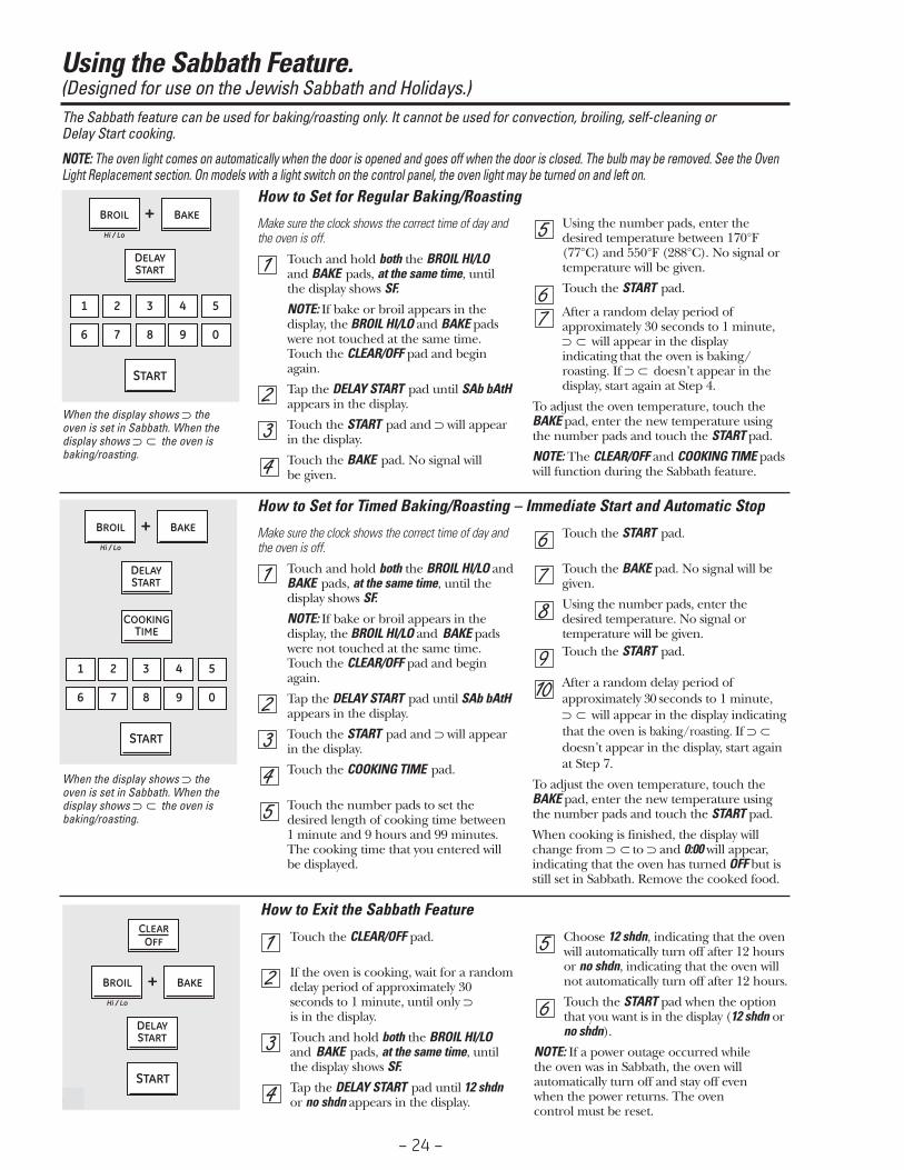
Using the Sabbath Feature.(Designed for use on the Jewish Sabbath and Holidays.)The Sabbath feature can be used for baking/roasting only. It cannot be used for convection, broiling, self-cleaning or Delay Start cooking.
NOTE: The oven light comes on automatically when the door is opened and goes off when the door is closed. The bulb may be removed. See the OvenLight Replacement section. On models with a light switch on the control panel, the oven light may be turned on and left on.
How to Set for Regular Baking/Roasting
Make sure the clock shows the correct time of day andthe oven is off.
Touch and hold both the BROIL HI/LO and BAKE pads, at the same time, untilthe display shows SF.
NOTE: If bake or broil appears in thedisplay, the BROIL HI/LO and BAKE padswere not touched at the same time.Touch the CLEAR/OFF pad and beginagain.
Tap the DELAY START pad until SAb bAtHappears in the display.
Touch the START pad and ⊃ will appearin the display.
Touch the BAKE pad. No signal will be given.
Using the number pads, enter thedesired temperature between 170°F(77°C) and 550°F (288°C). No signal ortemperature will be given.
Touch the START pad.
After a random delay period ofapproximately 30 seconds to 1 minute,⊃ will appear in the displayindicating that the oven is baking/roasting. If ⊃ doesn’t appear in thedisplay, start again at Step 4.
To adjust the oven temperature, touch theBAKE pad, enter the new temperature usingthe number pads and touch the START pad.
NOTE: The CLEAR/OFF and COOKING TIME padswill function during the Sabbath feature.
⊃
⊃
+
How to Set for Timed Baking/Roasting – Immediate Start and Automatic Stop
Make sure the clock shows the correct time of day andthe oven is off.
Touch and hold both the BROIL HI/LO andBAKE pads, at the same time, until thedisplay shows SF.
NOTE: If bake or broil appears in thedisplay, the BROIL HI/LO and BAKE padswere not touched at the same time.Touch the CLEAR/OFF pad and beginagain.
Tap the DELAY START pad until SAb bAtHappears in the display.
Touch the START pad and ⊃ will appearin the display.
Touch the COOKING TIME pad.
Touch the number pads to set thedesired length of cooking time between 1 minute and 9 hours and 99 minutes.The cooking time that you entered will be displayed.
Touch the START pad.
Touch the BAKE pad. No signal will begiven.
Using the number pads, enter thedesired temperature. No signal ortemperature will be given. Touch the START pad.
After a random delay period ofapproximately 30 seconds to 1 minute,⊃ will appear in the display indicatingthat the oven is baking/roasting. If ⊃doesn’t appear in the display, start againat Step 7.
To adjust the oven temperature, touch theBAKE pad, enter the new temperature usingthe number pads and touch the START pad.
When cooking is finished, the display willchange from ⊃ to ⊃ and 0:00 will appear,indicating that the oven has turned OFF but isstill set in Sabbath. Remove the cooked food.
⊃
⊃⊃
+
How to Exit the Sabbath Feature
Touch the CLEAR/OFF pad.
If the oven is cooking, wait for a randomdelay period of approximately 30seconds to 1 minute, until only ⊃ is in the display.
Touch and hold both the BROIL HI/LOand BAKE pads, at the same time, untilthe display shows SF.
Tap the DELAY START pad until 12 shdnor no shdn appears in the display.
Choose 12 shdn, indicating that the ovenwill automatically turn off after 12 hoursor no shdn, indicating that the oven willnot automatically turn off after 12 hours.
Touch the START pad when the optionthat you want is in the display (12 shdn orno shdn).
NOTE: If a power outage occurred while the oven was in Sabbath, the oven willautomatically turn off and stay off even when the power returns. The oven control must be reset.
When the display shows ⊃ theoven is set in Sabbath. When thedisplay shows ⊃ the oven isbaking/roasting.
⊃
When the display shows ⊃ theoven is set in Sabbath. When thedisplay shows ⊃ the oven isbaking/roasting.
⊃

– 25 –
Component Locator Views
(Continued next page)
Front View (PGS975 Shown)
Storage Drawer Compartment
(Shown with Storage Drawer Removed)
Convection Fan
Control Panel Assembly
Broil Burner
Storage Drawer
Broil Burner Igniter
Oven Gas Shut-Off
Oven Temperature Sensor
Bake Burner Under Bottom Pan
LP Gas Conversion Kit
Meat Probe Outlet
Regulator
Halogen Lamp (1 of 2)

– 26 –(Continued next page)
Burner Assembly (PGS975 Shown)
Burner Cap
Oven Vent
Maintop Burner Assembly
(PGS975 Shown with Grates Removed)
Igniter (Electrode)
Burner Orifi ce
Burner Orifi ce
Burner Base
Burner Head Assembly
T-20 Torx Screws
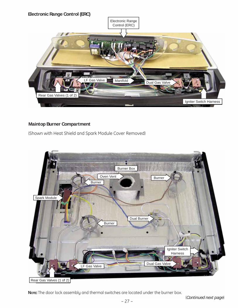
– 27 –
Maintop Burner Compartment
(Shown with Heat Shield and Spark Module Cover Removed)
Electronic Range Control (ERC)
BurnerBurner
Burner
Oven Vent
Rear Gas Valves (1 of 2)
(Continued next page)
Manifold
Igniter Switch Harness
Rear Gas Valves (1 of 2)
Burner Box
NOTE: The door lock assembly and thermal switches are located under the burner box.
Dual Gas Valve
Dual Burner
Igniter Switch Harness
LF Gas Valve
Dual Gas ValveLF Gas Valve
Electronic Range Control (ERC)
Spark Module
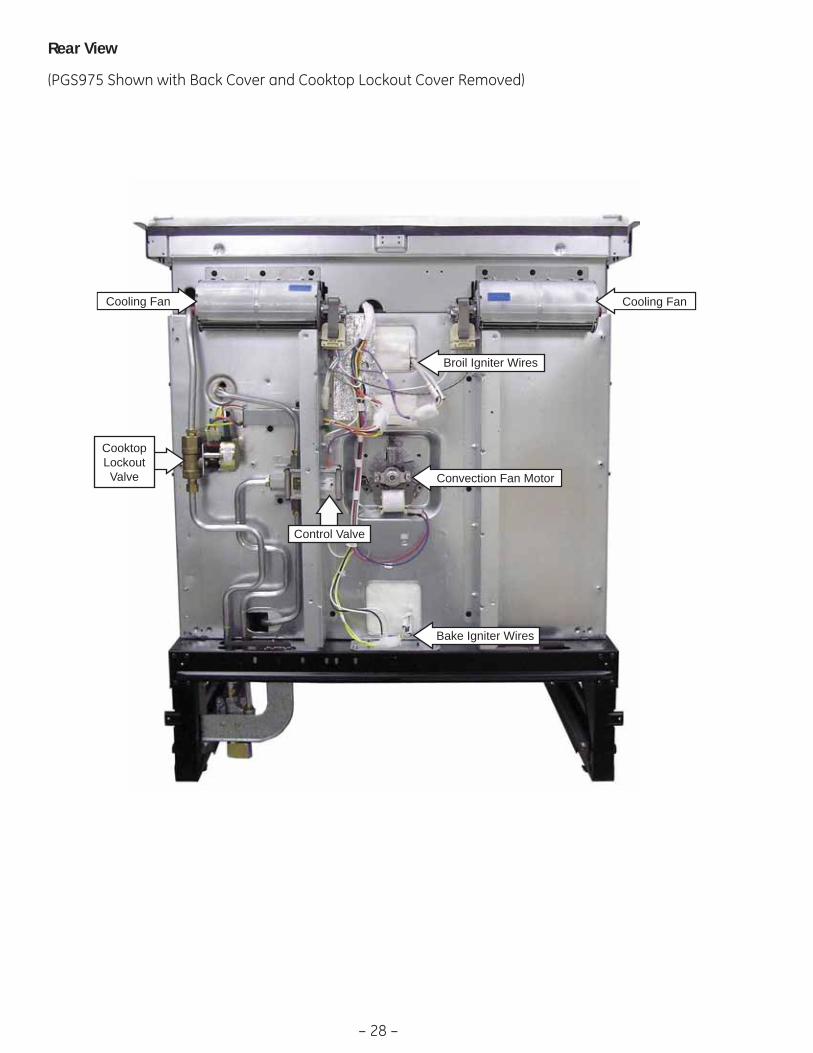
– 28 –
Rear View
(PGS975 Shown with Back Cover and Cooktop Lockout Cover Removed)
Convection Fan Motor
Broil Igniter Wires
Bake Igniter Wires
Cooling Fan Cooling Fan
Control Valve
Cooktop Lockout Valve
– 29 –
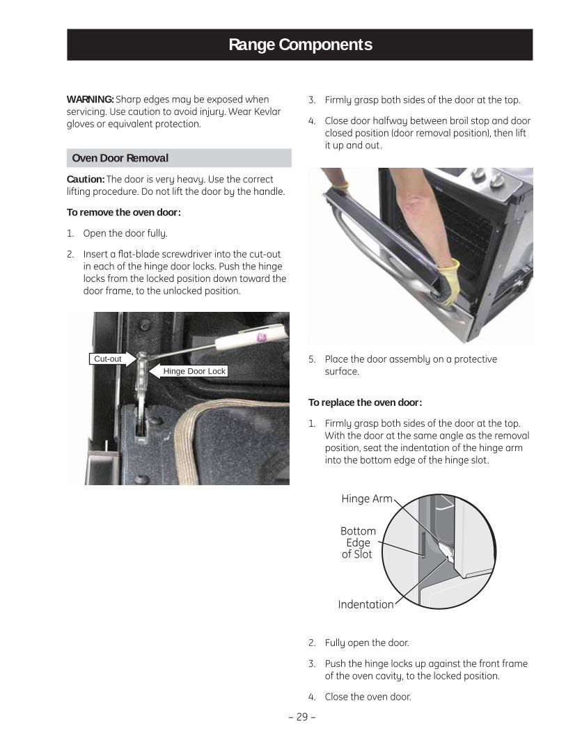
Range Components
WARNING: Sharp edges may be exposed when servicing. Use caution to avoid injury. Wear Kevlar gloves or equivalent protection.
Oven Door Removal
Caution: The door is very heavy. Use the correct lifting procedure. Do not lift the door by the handle.
To remove the oven door:
Open the door fully.1.
Insert a fl at-blade screwdriver into the cut-out 2. in each of the hinge door locks. Push the hinge locks from the locked position down toward the door frame, to the unlocked position.
Hinge Door LockCut-out
Firmly grasp both sides of the door at the top.3.
Close door halfway between broil stop and door 4. closed position (door removal position), then lift it up and out.
To replace the oven door:
Firmly grasp both sides of the door at the top. 1. With the door at the same angle as the removal position, seat the indentation of the hinge arm into the bottom edge of the hinge slot.
Fully open the door.2.
Push the hinge locks up against the front frame 3. of the oven cavity, to the locked position.
Close the oven door.4.
Place the door assembly on a protective 5. surface.

– 30 –
Oven Door Assembly
The oven door can be separated into 2 assemblies. The outer assembly consists of the outer panel, reinforcement plate, and a replaceable door handle. The inner assembly is made up of the inner panel, inner glass assembly, retainers, heat barrier, door gasket, and replaceable door hinge assemblies.
To remove the outer door assembly:
Remove the door. (See 1. Oven Door Removal.)
Place the door assembly, gasket side up, on a 2. protective surface.
Remove the four T-15 Torx screws from the 3. bottom of the outer door assembly.
Remove the four T-15 Torx screws (2 on each 4. side) from the outer door assembly.
Note: The inner door assembly is heavier than the outer door assembly.
Separate the inner door assembly from the 5. outer door assembly.
Remove the four ¼-in. hex-head screws that 6. hold the door handle and the reinforcement plate to the outer door assembly.
To replace the inner door assembly:
Remove the outer door assembly. (See 1. To remove the outer door assembly.)
Remove the four T-20 Torx screws (2 on each 2. side) that attach each door hinge to the inner door. Carefully turn the door over and remove both door hinges.
Remove the four ¼-in. hex-head screws that 3. attach the glass and side brackets (glass closest to the outer door glass) to the inner door.
(Continued next page)
– 31 –
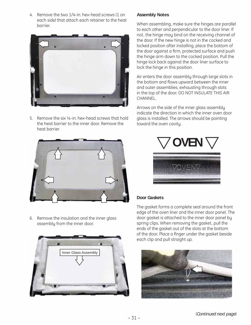
Remove the six ¼-in. hex-head screws that hold 5. the heat barrier to the inner door. Remove the heat barrier.
Remove the two 1/4-in. hex-head screws (1 on 4. each side) that attach each retainer to the heat barrier.
Remove the insulation and the inner glass 6. assembly from the inner door.
Inner Glass Assembly
Assembly Notes
When assembling, make sure the hinges are parallel to each other and perpendicular to the door liner. If not, the hinge may bind on the receiving channel of the door. If the new hinge is not in the cocked and locked position after installing, place the bottom of the door against a fi rm, protected surface and push the hinge arm down to the cocked position. Pull the hinge lock back against the door liner surface to lock the hinge in this position.
Air enters the door assembly through large slots in the bottom and fl ows upward between the inner and outer assemblies, exhausting through slots in the top of the door. DO NOT INSULATE THIS AIR CHANNEL.
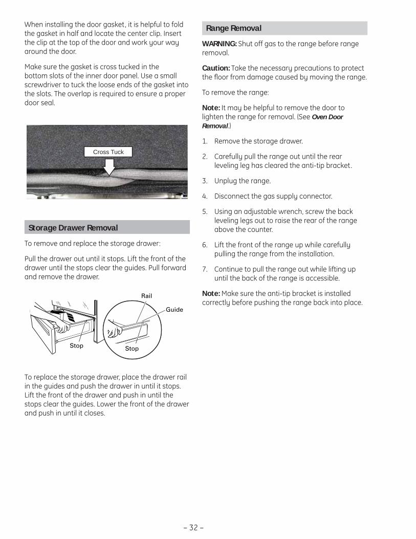
Arrows on the side of the inner glass assembly indicate the direction in which the inner oven door glass is installed. The arrows should be pointing toward the oven cavity.
OVEN
Door Gaskets
The gasket forms a complete seal around the front edge of the oven liner and the inner door panel. The door gasket is attached to the inner door panel by spring clips. When removing the gasket, pull the ends of the gasket out of the slots at the bottom of the door. Place a fi nger under the gasket beside each clip and pull straight up.
(Continued next page)
– 32 –
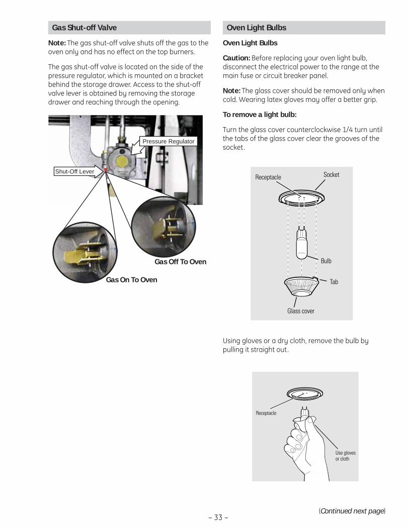
When installing the door gasket, it is helpful to fold the gasket in half and locate the center clip. Insert the clip at the top of the door and work your way around the door.
Make sure the gasket is cross tucked in the bottom slots of the inner door panel. Use a small screwdriver to tuck the loose ends of the gasket into the slots. The overlap is required to ensure a proper door seal.
Cross Tuck
Storage Drawer Removal
To remove and replace the storage drawer:
Pull the drawer out until it stops. Lift the front of the drawer until the stops clear the guides. Pull forward and remove the drawer.
To replace the storage drawer, place the drawer rail in the guides and push the drawer in until it stops. Lift the front of the drawer and push in until the stops clear the guides. Lower the front of the drawer and push in until it closes.
Rail
Guide
StopStop
Range Removal
WARNING: Shut off gas to the range before range removal.
Caution: Take the necessary precautions to protect the fl oor from damage caused by moving the range.
To remove the range:
Note: It may be helpful to remove the door to lighten the range for removal. (See Oven Door Removal.)
Remove the storage drawer.1.
Carefully pull the range out until the rear 2. leveling leg has cleared the anti-tip bracket.
Unplug the range.3.
Disconnect the gas supply connector.4.
Using an adjustable wrench, screw the back 5. leveling legs out to raise the rear of the range above the counter.
Lift the front of the range up while carefully 6. pulling the range from the installation.
Continue to pull the range out while lifting up 7. until the back of the range is accessible.
Note: Make sure the anti-tip bracket is installed correctly before pushing the range back into place.
– 33 –
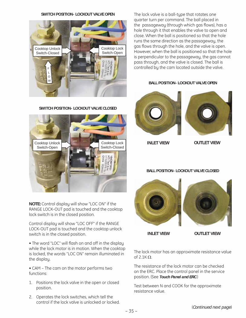
Shut-Off Lever
Pressure Regulator
Gas On To Oven
Gas Off To Oven
Oven Light Bulbs
Oven Light Bulbs
Caution: Before replacing your oven light bulb, disconnect the electrical power to the range at the main fuse or circuit breaker panel.
Note: The glass cover should be removed only when cold. Wearing latex gloves may offer a better grip.
To remove a light bulb:
Turn the glass cover counterclockwise 1/4 turn until the tabs of the glass cover clear the grooves of the socket.
Bulb
Socket
Tab
Glass cover
Receptacle
Using gloves or a dry cloth, remove the bulb by pulling it straight out.
Use glovesor cloth
Receptacle
(Continued next page)
Gas Shut-off Valve
Note: The gas shut-off valve shuts off the gas to the oven only and has no effect on the top burners.
The gas shut-off valve is located on the side of the pressure regulator, which is mounted on a bracket behind the storage drawer. Access to the shut-off valve lever is obtained by removing the storage drawer and reaching through the opening.

– 34 –
To replace a light bulb, use a new 130-volt halogen bulb, not to exceed 50 watts.
Note:
Higher wattage bulbs will damage your oven.•
Using gloves or a dry cloth, remove the bulb • from its packaging. Do not touch the bulb with bare fi ngers. Oil from bare fi ngers may cause hot spots on the glass surface and lead to premature failure of the bulb. If you do touch the glass, clean it with alcohol prior to installation.
Push the bulb straight into the receptacle all the 1. way.
Place the tabs of the glass cover into the 2. grooves of the socket. Turn the glass cover clockwise 1/4 turn.
Note: For improved lighting inside the oven, clean the glass cover frequently using a wet cloth. This should be done when the oven is completely cool.
Reconnect electrical power to the oven.3.
Lockout Valve
The range lockout feature (on some models), will allow the user to lock out the surface burners, oven burners, and control panel so they cannot be activated. (See Control Features.) The purpose of the lockout valve is to shut-off the gas supply to the surface burners when this feature is selected.
Note: The cooktop is locked out when the oven is in self-clean mode. (See Control Features.)
The lockout valve assembly consists of a valve lock motor, cam and switch assembly, lock valve, and mounting plate.
The lock motor is energized when the control is set for RANGE LOCK-OUT. The control RY4 relay will close and complete the circuit that supplies the voltage to the valve lock motor.
(Continued next page)
COOKTOP LOCK
COOKTOPUNLOCK
CN6
COOKTOPLOCK
COOKTOPUNLOCK
CN6
SWITCH CIRCUIT- LOCKOUT VALVE CLOSED
SWITCH CIRCUIT- LOCKOUT VALVE OPEN
Note: When the door is either being locked or unlocked, both lock switches will be in the open position.
Rear Cover Removal
To access the rear cover it is necessary to remove the range from its installation. (See Range Removal.) The cover is attached to the range with six 1/4-in. hex-head screws located along the outer edge and six 1/4-in. hex-head screws located on the back.
– 35 –
NOTE: Control display will show "LOC ON" if the RANGE LOCK-OUT pad is touched and the cooktop lock switch is in the closed position.
Control display will show "LOC OFF" if the RANGE LOCK-OUT pad is touched and the cooktop unlock switch is in the closed position.
• The word "LOC" will fl ash on and off in the display while the lock motor is in motion. When the cooktop is locked, the words “LOC ON” remain illuminated in the display.
• CAM – The cam on the motor performs two functions:
Positions the lock valve in the open or closed 1. position.
Operates the lock switches, which tell the 2. control if the lock valve is unlocked or locked.
The lock valve is a ball-type that rotates one quarter turn per command. The ball placed in the passageway (through which gas fl ows), has a hole through it that enables the valve to open and close. When the ball is positioned so that the hole runs the same direction as the passageway, the gas fl ows through the hole, and the valve is open. However, when the ball is positioned so that the hole is perpendicular to the passageway, the gas cannot pass through, and the valve is closed. The ball is controlled by the cam located outside the valve.
SWITCH POSITION- LOCKOUT VALVE OPEN
SWITCH POSITION- LOCKOUT VALVE CLOSED
BALL POSITION- LOCKOUT VALVE OPEN
INLET VIEW OUTLET VIEW
INLET VIEW OUTLET VIEW
BALL POSITION- LOCKOUT VALVE CLOSED
Cooktop Unlock Switch-Closed
Cooktop Unlock Switch-Open
Cooktop Lock Switch-Open
Cooktop Lock Switch-Closed
(Continued next page)
FLOW
The lock motor has an approximate resistance value of 2.1K Ω.
The resistance of the lock motor can be checked on the ERC. Place the control panel in the service position. (See Touch Panel and ERC.)
Test between N and COOK for the approximate resistance value.

– 36 –
Carefully remove the tubes from the valve. 7.
Remove the 1/4-in. hex-head screw that 8. attaches the valve to the range.
Note: When installing the lockout valve, be sure that the cutout in the bottom of the valve is engaged behind the tab on the back of the range.
Tab
Cutout
Disconnect the wires from the lockout valve.5.
Using an 11/16-in. wrench, disconnect the inlet 6. and outlet tube hex-head nuts from the valve.
Cover
Disconnect Wires
Lockout Valve
To remove the lockout valve:
Remove the oven door. (See 1. Oven Door Removal.)
Remove the range from the installation. (See 2. Range Removal.)
Remove the rear cover. (See 3. Rear Cover Removal.)
Remove the two 1/4-in. hex-head screws and 4. the lockout valve cover.

– 37 –
Cooling Fans
The PGS908 and PGS975 use 2 cooling fans for cooling the oven components. The PGS968 uses a single fan. The cooling fans are located on the rear of the range. Air is pulled in by the fan blades and circulated in the component compartment located under the burner box. The air is exhausted through louvers below the control panel and out the slots above the door.
Cooling Timing Parameters PGS908
The cooling fans will not turn on immediately when a cooking function is set. THEY WILL TURN ON AFTER 12 MINUTES. The cooling fan comes on when the oven is on. If the temperature is over 300°F (149°C) and the oven is turned off, the fans will remain on until the temperature drops below 300°F (149°C).
Cooling Timing Parameters PGS968
The cooling fan comes on when the oven is on. If the temperature is set over 300°F (149°C) and the oven is turned off, the fan will remain on until the temperature drops below 300°F (149°C) or 85 minutes has elapsed.
Cooling Timing Parameters PGS975
The cooling fans will not turn on immediately when a cooking function is set. THEY WILL TURN ON AFTER 12 MINUTES. If the temperature is set over 300°F (149°C) and the oven is turned off, the fans will remain on until the temperature drops below 300°F (149°C) or 85 minutes has elapsed.
The resistance of the cooling fan(s) can be checked on the ERC. Place the control panel in the service position. (See Touch Panel and ERC.)
PGS908 - To check both fans, test between N and J4 pin 1.
PGS968 and PGS975 - To check the fan(s), test between N and LIGHT FOD.
Each cooling fan has an approximate resistance value of 24 Ω.
PGS908 and PGS975 - The approximate parallel resistance value of the 2 fans is 13.4 Ω. A value of approximately 24 Ω indicates an open fan motor or wiring.
PGS968 - The approximate resistance value of the
Remove the four 1/4-in. hex-head screws and 6. the bracket attached to the cooling fan.
Disconnect Wires
Bracket
To remove the cooling fan(s):
Remove the oven door. (See 1. Oven Door Removal.)
Remove the range from the installation. (See 2. Range Removal.)
Remove the rear cover. (See 3. Rear Cover Removal.)
Disconnect wires to the cooling fan.4.
Remove the three 1/4-in. hex-head screws and 5. the cooling fan.
– 38 –
Hinge Receiver
The oven door hinge receiver is attached to the frame with two T-15 Torx screws. To replace it requires removing the range from the installation. (See Range Removal.)
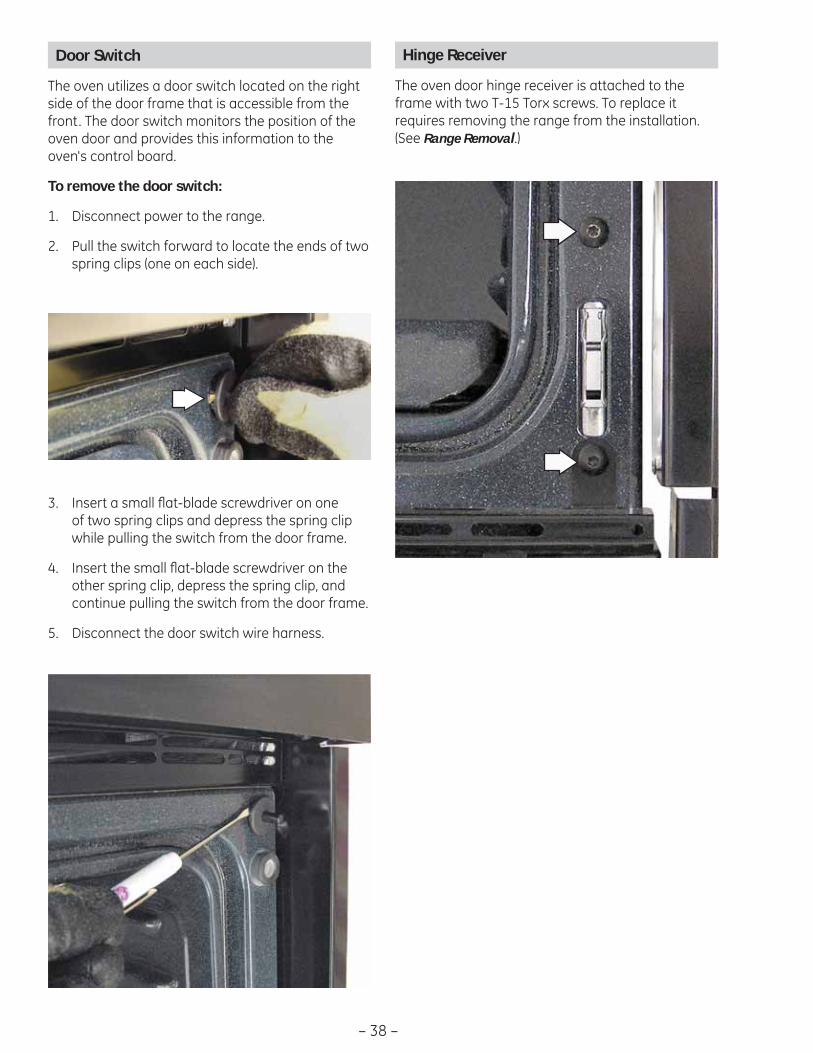
Door Switch
The oven utilizes a door switch located on the right side of the door frame that is accessible from the front. The door switch monitors the position of the oven door and provides this information to the oven's control board.
To remove the door switch:
Disconnect power to the range.1.
Pull the switch forward to locate the ends of two 2. spring clips (one on each side).
Insert a small fl at-blade screwdriver on one 3. of two spring clips and depress the spring clip while pulling the switch from the door frame.
Insert the small fl at-blade screwdriver on the 4. other spring clip, depress the spring clip, and continue pulling the switch from the door frame.
Disconnect the door switch wire harness.5.

– 39 –
Oven Components
Oven Burner Ignition System
The oven bake and broil burners are ignited by a glow-bar ignition system. The igniter is a Norton style rectangular glow-bar. The bake and broil ignition circuits consist of the electronic control, an igniter, and an oven safety valve. The three components are wired in series for each cooking function.
The most important points to know about the ignition system are:
• THE IGNITER RESISTANCE DECREASES AS THE IGNITER SURFACE TEMPERATURE INCREASES.
• THE SAFETY VALVE OPERATES BY CURRENT, NOT VOLTAGE.
From a cold start, the igniter needs 30 to 60 seconds, with a minimum of 116 volts applied, to reduce its electrical resistance enough to provide a minimum of 2.9 amps of current fl ow in the series circuit. This is the required current fl ow needed for the safety valve to open and supply gas to the burner.
The glow-bar should provide a steady current fl ow of 3.3 to 3.6 amps (3.03 / 3.3 VAC) in the circuit. At that point, the igniter temperature is 1800°F to 2500°F (982°C to 1371°C). The igniter will remain energized at all times during burner operation. If the igniter glows red but does not draw at least 2.9 amps, the fault is usually with the igniter, not the valve.
Always check the gas shut-off valve on the pressure regulator for a Not On condition.
Note: If igniter glows, but ignition does not occur, be sure the gas shut-off valve on the pressure regulator is in the open position.
Slow ignition can be caused by one or more of the following conditions:
Blockage of primary air intake: Hole beneath 1. the bake orifi ce hood must be open and free of insulation.
Blockage of secondary air intake holes: 2. Examine oven burner box (galvanized box surrounding oven burner) and inspect the single row of secondary holes beneath the bake burner for signs of blockage. Also, be sure items in the storage drawer so not push against the ceiling of the drawer area. If pushed hard enough, the ceiling will fl ex upward, closing off the secondary air holes.
Improper alignment of orifi ce hood and burner: 3. Orifi ce must be pointing straight into burner venturi.
Improper air/gas adjustment.4.
Blockage of burner crossover slots: Crossover 5. slots must be open and free of burrs.
Improper installation: Failure to seal all openings 6. in the wall behind and fl oor below the range may permit substantial drafts, which can affect ignition.
The gas control valve should draw 7. approximately 3.3 to 3.6 amps when operating. Check by measuring the amperage in L1 to the oven control. This can be done by removing the control panel glass and clock/insert assembly.
Glow-bar Igniter
WARNING: This range uses rectangular Norton glow-bar igniters. They are NOT INTERCHANGEABLE with cylindrical Carborundum glow-bar igniters. The two types of glow-bar igniters operate at different amperage and use different gas valves.
Check the glow-bar circuit with a clamp-on ammeter. If igniter glows red but circuit does not draw at least 2.9 amps, the fault is likely with the igniter, not the valve.

– 40 –
Broil Burner and Glo-bar Igniter
The broil burner glow-bar igniter has an approximate resistance value of 175 Ω at room temperature.
The resistance of the broil burner glow-bar igniter can be checked on the ERC. Place the control panel in the service position. (See Touch Panel and ERC.)
PGS908 - Test between the BR and N.
PGS968 and PGS975 - Test between the violet wire on relay RY11 and N.
An open measurement indicates an open igniter, broil circuit in the control valve, or open wiring.
To remove the broil burner and glo-bar igniter:
Remove the oven door. (See 1. Oven Door Removal.)
Remove the two 1/4-in. hex-head screws that 2. hold the shield to the bottom of the broil burner.
Remove the two 1/4-in. hex-head screws that 3. attach the glo-bar igniter to the side of the broil burner.
Gently pull the igniter wiring and harness 4. through the oven wall, and disconnect the harness.
Note: Ensure displaced insulation around the wiring entry hole is returned to it's original position.
Remove the 1/4-in. hex-head screw that holds 5. the burner in place and remove the burner.
Note: When installing the broil burner, be sure the orifi ce hood is inserted into the burner inlet opening.
– 41 –
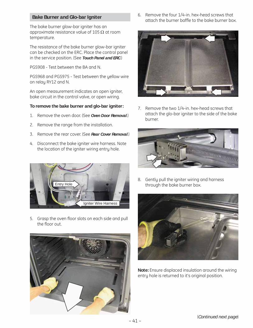
Bake Burner and Glo-bar Igniter
The bake burner glow-bar igniter has an approximate resistance value of 105 Ω at room temperature.
The resistance of the bake burner glow-bar igniter can be checked on the ERC. Place the control panel in the service position. (See Touch Panel and ERC.)
PGS908 - Test between the BA and N.
PGS968 and PGS975 - Test between the yellow wire on relay RY12 and N.
An open measurement indicates an open igniter, bake circuit in the control valve, or open wiring.
To remove the bake burner and glo-bar igniter:
Remove the oven door. (See 1. Oven Door Removal.)
Remove the range from the installation.2.
Remove the rear cover. (See 3. Rear Cover Removal.)
Disconnect the bake igniter wire harness. Note 4. the location of the igniter wiring entry hole.
Grasp the oven fl oor slots on each side and pull 5. the fl oor out.
Remove the two 1/4-in. hex-head screws that 7. attach the glo-bar igniter to the side of the bake burner.
Remove the four 1/4-in. hex-head screws that 6. attach the burner baffl e to the bake burner box.
Gently pull the igniter wiring and harness 8. through the bake burner box.
Note: Ensure displaced insulation around the wiring entry hole is returned to it's original position.
Igniter Wire Harness
Entry Hole
(Continued next page)
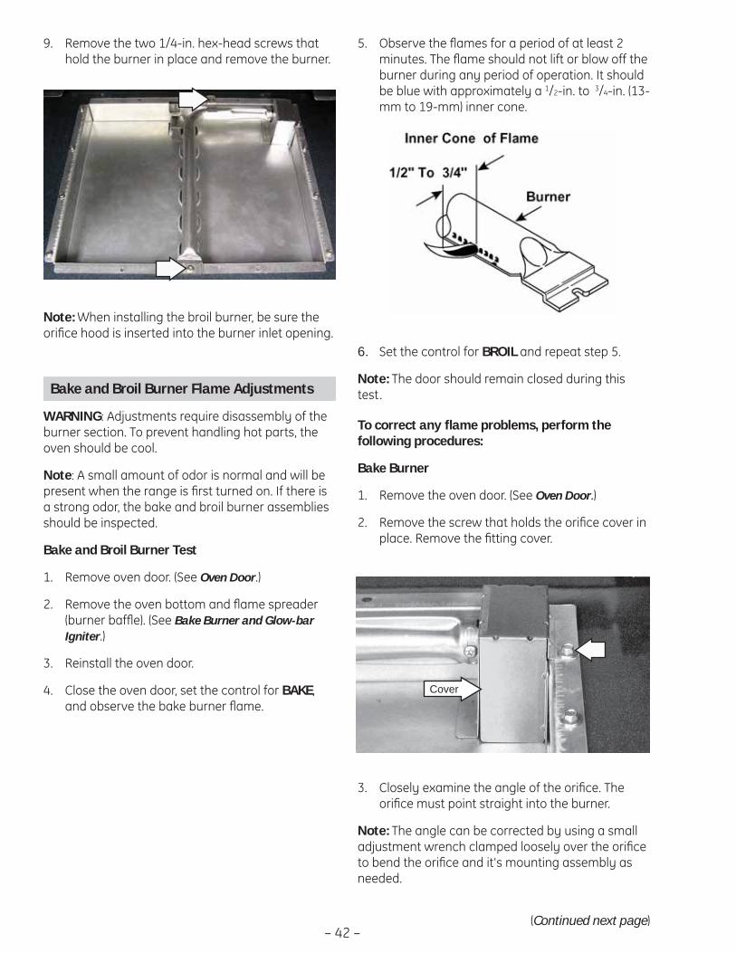
– 42 –
Remove the two 1/4-in. hex-head screws that 9. hold the burner in place and remove the burner.
Note: When installing the broil burner, be sure the orifi ce hood is inserted into the burner inlet opening.
Bake and Broil Burner Flame Adjustments
WARNING: Adjustments require disassembly of the burner section. To prevent handling hot parts, the oven should be cool.
Note: A small amount of odor is normal and will be present when the range is fi rst turned on. If there is a strong odor, the bake and broil burner assemblies should be inspected.
Bake and Broil Burner Test
Remove oven door. (See 1. Oven Door.)
Remove the oven bottom and fl ame spreader 2. (burner baffl e). (See Bake Burner and Glow-bar Igniter.)
Reinstall the oven door. 3.
Close the oven door, set the control for 4. BAKE, and observe the bake burner fl ame.
6. Set the control for BROIL and repeat step 5.
Note: The door should remain closed during this test.
(Continued next page)
To correct any fl ame problems, perform the following procedures:
Bake Burner
Remove the oven door. (See 1. Oven Door.)
Remove the screw that holds the orifi ce cover in 2. place. Remove the fi tting cover.
Cover
Observe the fl ames for a period of at least 2 5. minutes. The fl ame should not lift or blow off the burner during any period of operation. It should be blue with approximately a 1/2-in. to 3/4-in. (13-mm to 19-mm) inner cone.
Closely examine the angle of the orifi ce. The 3. orifi ce must point straight into the burner.
Note: The angle can be corrected by using a small adjustment wrench clamped loosely over the orifi ce to bend the orifi ce and it's mounting assembly as needed.

– 43 –
Inspect the primary air opening. The opening 4. must be clear and free of insulation all the way down to the metal shield below (0.314-in. [8.0 mm] opening).
Use a screwdriver to loosen the air shutter 5. screw.
6. Using a drill bit as a gauge, adjust the air shutter to 11/32 in. (8.7 mm).
a. If the fl ames were yellow during the test, open the air shutter an additional 1/32 in. (0.79 mm.)
b. If the fl ames blow away or fl uttered from the burner during the test, close the air shutter an additional 1/32 in. (0.79 mm).
11/32
3. Closely examine the angle of the orifi ce. The hood must point straight into the burner.
Note: The angle can be corrected by using a small adjustment wrench clamped loosely over the orifi ce to bend the orifi ce and its mounting assembly as needed.
4. Inspect the primary air opening. The opening must be clear all the way down to the metal shield below the 0.314 in. (8.0 mm) opening.
5. Use a screwdriver to loosen the air shutter screw.
Retighten the air shutter screw and replace the 7. orifi ce fi tting cover.
Note: The cover must be as airtight as possible. Bend the cover to close off gaps between the sides and the top of the cover.
8. Install and close the oven door. Before installing the baffl e and bottom pan, set the control for BAKE and observe the bake burner fl ame for any fl ame problems.
Note: Examine the burner baffl e for signs of warp-age. If warped, baffl e will have to be replaced.
9. Install the burner baffl e and bottom pan. With the customer present, test oven from a cold start to be sure any odor problems have been corrected.
Broil Burner
The broil burner is accessible and located in the top center of the oven.
1. Remove the oven door. (See Oven Door.)
2. Remove the broil burner. (See Broil Burner and Glow-bar Igniter.)
Adjust the air shutter to 6. 11/32 in. (8.7 mm).
a. If the fl ames were yellow during the test, open the air shutter an additional 1/32 in. (0.79 mm).
b. If the fl ames blow away or fl uttered from the burner during the test, close the air shutter an additional 1/32 in. (0.79 mm).
11/32
Retighten the air shutter screw.7.
8. Install the oven door. Set the control for Broil and observe the broil burner fl ame for any fl ame problems.
9. With the customer present, test the oven from a cold start to be sure any odor problems have been corrected.
LP and Natural Gas Information
LP Gas Installations: If fl ames lift off the burner and appear unstable, reduce the air shutter openings an additional 1/32 in. (0.79 mm), cool the oven, and perform the Bake and Broil Burner Test. If fl ames are too large but appear stable, check to be sure the oven was properly converted.
Natural Gas Installations: If fl ames are too large but appear stable, tighten the orifi ce hood to reduce the gas fl ow to the burner.
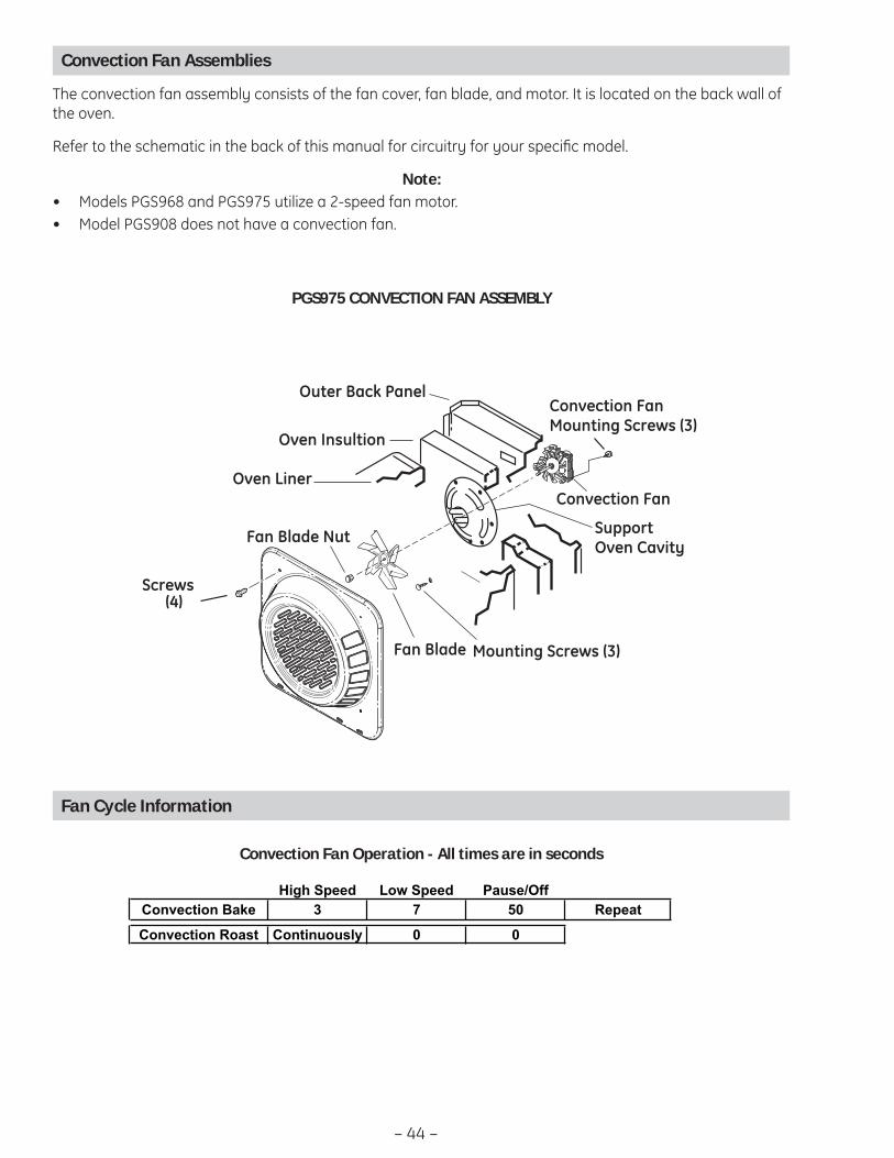
– 44 –
Convection Fan Assemblies
The convection fan assembly consists of the fan cover, fan blade, and motor. It is located on the back wall of the oven.
Refer to the schematic in the back of this manual for circuitry for your specifi c model.
Note: Models PGS968 and PGS975 utilize a 2-speed fan motor.• Model PGS908 does not have a convection fan.•
Fan Blade
Oven Liner
Oven Insultion
Outer Back Panel
Convection Fan
Screws(4)
Support Oven Cavity
Mounting Screws (3)
Convection Fan Mounting Screws (3)
Fan Blade Nut
PGS975 CONVECTION FAN ASSEMBLY
Fan Cycle Information
Fan will only start to operate 10 seconds after the burners turn off.
The fan will only run in one direction with the following parameters:
High Speed Low Speed Pause/Off
Convection Bake 3 7 50 Repeat
Convection Roast Continuously 0 0
Convection Fan Operation - All times are in seconds
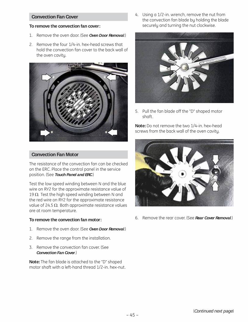
– 45 –
Pull the fan blade off the "D" shaped motor 5. shaft.
Note: Do not remove the two 1/4-in. hex-head screws from the back wall of the oven cavity.
Convection Fan Cover
To remove the convection fan cover:
Remove the oven door. (See 1. Oven Door Removal.)
Remove the four 1/4-in. hex-head screws that 2. hold the convection fan cover to the back wall of the oven cavity.
Using a 1/2-in. wrench, remove the nut from 4. the convection fan blade by holding the blade securely and turning the nut clockwise.
(Continued next page)
Convection Fan Motor
The resistance of the convection fan can be checked on the ERC. Place the control panel in the service position. (See Touch Panel and ERC.)
Test the low speed winding between N and the blue wire on RY2 for the approximate resistance value of 19 Ω. Test the high speed winding between N and the red wire on RY2 for the approximate resistance value of 24.5 Ω. Both approximate resistance values are at room temperature.
To remove the convection fan motor:
Remove the oven door. (See 1. Oven Door Removal.)
Remove the range from the installation.2.
Remove the convection fan cover. (See 3. Convection Fan Cover.)
Note: The fan blade is attached to the "D" shaped motor shaft with a left-hand thread 1/2-in. hex-nut.
Remove the rear cover. (See 6. Rear Cover Removal.)
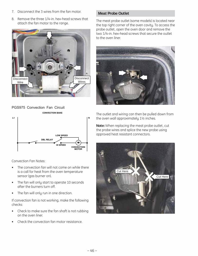
– 46 –
7. Disconnect the 3 wires from the fan motor.
Remove the three 1/4-in. hex-head screws that 8. attach the fan motor to the range.
Disconnect Wires
Disconnect Wire
PGS975 Convection Fan Circuit
L1 N
CONVECTION BAKE
DBL RELAY
LOW SPEED
HI SPEEDM
CONVECTIONMOTOR
The outlet and wiring can then be pulled down from the oven wall approximately 1½ inches.
Note: When replacing the meat probe outlet, cut the probe wires and splice the new probe using approved heat resistant connectors.
Meat Probe Outlet
The meat probe outlet (some models) is located near the top right corner of the oven cavity. To access the probe outlet, open the oven door and remove the two 1/4-in. hex-head screws that secure the outlet to the oven liner.
Convection Fan Notes:
The convection fan will not come on while there • is a call for heat from the oven temperature sensor (gas burner on).
The fan will only start to operate 10 seconds • after the burners turn off.
The fan will only run in one direction.•
If convection fan is not working, make the following checks:
Check to make sure the fan shaft is not rubbing • on the oven liner.
Check the convection fan motor resistance. •
Cut Here
Cut Here
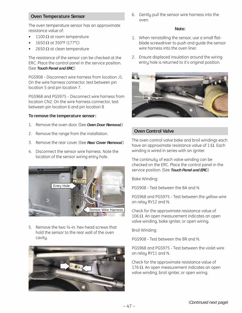
– 47 –
Remove the two ¼-in. hex-head screws that 5. hold the sensor to the rear wall of the oven cavity.
Oven Temperature Sensor
The oven temperature sensor has an approximate resistance value of:
1100 • Ω at room temperature1650 • Ω at 350°F (177°C)2650 • Ω at clean temperature
The resistance of the sensor can be checked at the ERC. Place the control panel in the service position. (See Touch Panel and ERC.)
PGS908 - Disconnect wire harness from location J1. On the wire harness connector, test between pin location 5 and pin location 7.
PGS968 and PGS975 - Disconnect wire harness from location CN2. On the wire harness connector, test between pin location 6 and pin location 8
To remove the temperature sensor:
Remove the oven door. (See 1. Oven Door Removal.)
Remove the range from the installation.2.
Remove the rear cover. (See 3. Rear Cover Removal.)
Disconnect the sensor wire harness. Note the 4. location of the sensor wiring entry hole.
Entry Hole
Sensor Wire Harness
(Continued next page)
Gently pull the sensor wire harness into the 6. oven.
Note:
When reinstalling the sensor, use a small fl at-1. blade screwdriver to push and guide the sensor wire harness into the oven liner.
Ensure displaced insulation around the wiring 2. entry hole is returned to it's original position.
Oven Control Valve
The oven control valve bake and broil windings each have an approximate resistance value of 1 Ω. Each winding is wired in series with an igniter.
The continuity of each valve winding can be checked on the ERC. Place the control panel in the service position. (See Touch Panel and ERC.)
Bake Winding:
PGS908 - Test between the BA and N.
PGS968 and PGS975 - Test between the yellow wire on relay RY12 and N.
Check for the approximate resistance value of 106 Ω. An open measurement indicates an open valve winding, bake igniter, or open wiring.
Broil Winding:
PGS908 - Test between the BR and N.
PGS968 and PGS975 - Test between the violet wire on relay RY11 and N.
Check for the approximate resistance value of 176 Ω. An open measurement indicates an open valve winding, broil igniter, or open wiring.
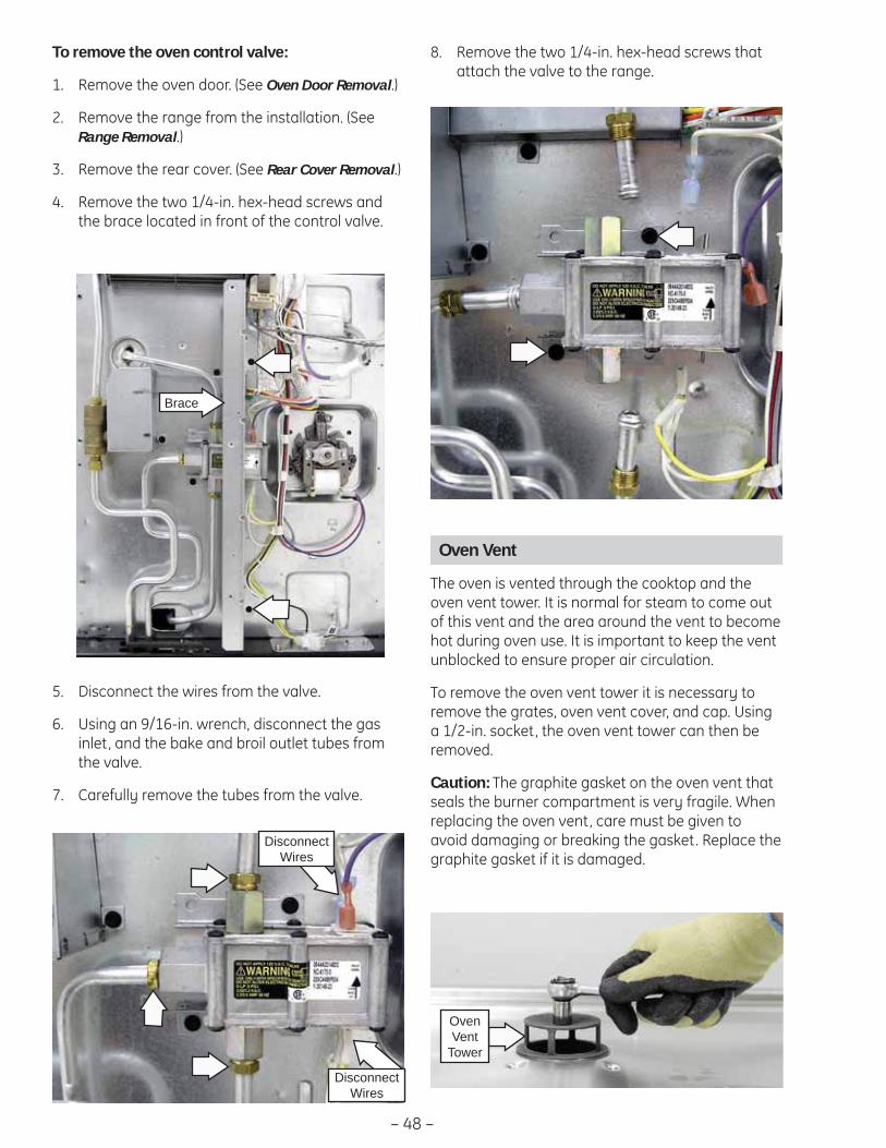
– 48 –
Disconnect the wires from the valve.5.
Using an 9/16-in. wrench, disconnect the gas 6. inlet, and the bake and broil outlet tubes from the valve.
Carefully remove the tubes from the valve. 7.
Disconnect Wires
Disconnect Wires
Remove the two 1/4-in. hex-head screws that 8. attach the valve to the range.
Oven Vent
The oven is vented through the cooktop and the oven vent tower. It is normal for steam to come out of this vent and the area around the vent to become hot during oven use. It is important to keep the vent unblocked to ensure proper air circulation.
To remove the oven vent tower it is necessary to remove the grates, oven vent cover, and cap. Using a 1/2-in. socket, the oven vent tower can then be removed.
Caution: The graphite gasket on the oven vent that seals the burner compartment is very fragile. When replacing the oven vent, care must be given to avoid damaging or breaking the gasket. Replace the graphite gasket if it is damaged.
Oven Vent
Tower
Brace
To remove the oven control valve:
Remove the oven door. (See 1. Oven Door Removal.)
Remove the range from the installation. (See 2. Range Removal.)
Remove the rear cover. (See 3. Rear Cover Removal.)
Remove the two 1/4-in. hex-head screws and 4. the brace located in front of the control valve.

– 49 –
Oven Light Assemblies
The model PGS908 oven is equipped with one halogen light assembly. Two light assemblies are installed on model PGS968 and PGS975. Each light assembly is located on the ceiling of the oven liner. The oven door switch monitors the position of the oven door and provides this information to the control board. The control board operates the light relay located on the control board. The lights come on when the OVEN LIGHT selection on the glass touch panel is activated, the door is opened, or when the oven is in a cooking cycle. The oven lights do not come on during self-cleaning or if the Sabbath Feature is set.
Each light assembly consists of a removable light cover, a light lens with halogen bulb and socket, and wire harness.
Each oven light bulb has an approximate resistance value of 26.8 Ω.
The resistance of the light bulb circuit can be checked on the ERC. Place the control panel in the service position. (See Touch Panel and ERC.)
Model PGS908: Open the door and test between L1 and N for the approximate resistance of 26.8 Ω.
Model PGS968 and PGS975: To check both bulbs, test between OVLT and the non-ribbed (line) side of the power cord for the approximate parallel resistance value of 13.6 Ω. A value of approximately 26.8 Ω indicates an open bulb or wiring.
The light assembly and wiring can then be pulled away from the oven liner approximately 2½ inches.
When replacing the light assembly, cut the wires and splice the new light assembly using approved heat resistant connectors.
To access each oven light assembly, open the oven door and remove the two 1/4-in. hex-head screws that attach the light assembly to the oven liner.

– 50 –
Control Panel Assembly
3. Carefully lift the glass touch panel and disconnect the ribbon connector.
4. Remove the eight 1/4-in. hex-head screws then lift the metal insert panel from the control panel frame.
Touch Panel and ERC
The glass touch panel and ERC are separate components but must be tested together.
TOUCH PANEL TEST
Press each pad on the touch panel followed by the start pad. If the touch panel is functioning properly, the following should occur:
BAKE, BROIL, CONVECTION BAKE (convection • models), CONVECTION ROAST (convection models), CLEAN, TIMER, CLOCK, STOP TIME, COOK TIME, PROOF, PROBE and RANGE LOCKOUT Modes – Audible tone plus display showing mode of operation selected.
CLEAR/OFF – Audible tone and display shows • time of day.
PROBE – Audible tone and response if meat • probe is plugged in.
Numerical Pads – Audible tone. Can only be • used after another function has been selected.
To remove the touch panel and ERC:
Disconnect power. 1.
Caution: In the following step, to prevent marring the fasteners or damaging the glass touch panel, if using a wrench or pliers, place a towel or cloth over each fastener.
Remove the knobs. Unscrew and remove the 4 2. hexagonal control panel fasteners.
WARNING: Components are electrically HOT on control when voltage is connected to range.
The control panel assembly consists of a glass touch panel (keypanel) and an ERC (Electronic Range Control) that is attached to a metal insert panel.
To replace the ERC it is necessary to disconnect the ribbon connector, and mark and disconnect the remaining wiring from the ERC. The ERC is attached to the metal insert panel with four 1/4-in. hex-head screws.
5. Position a protective surface over the top of the range and place the ERC in the service position.
6. Remove the 2 connectors from the ERC and disconnect the 12-pin wire harness.
Service Position
Fastener (1 of 4)
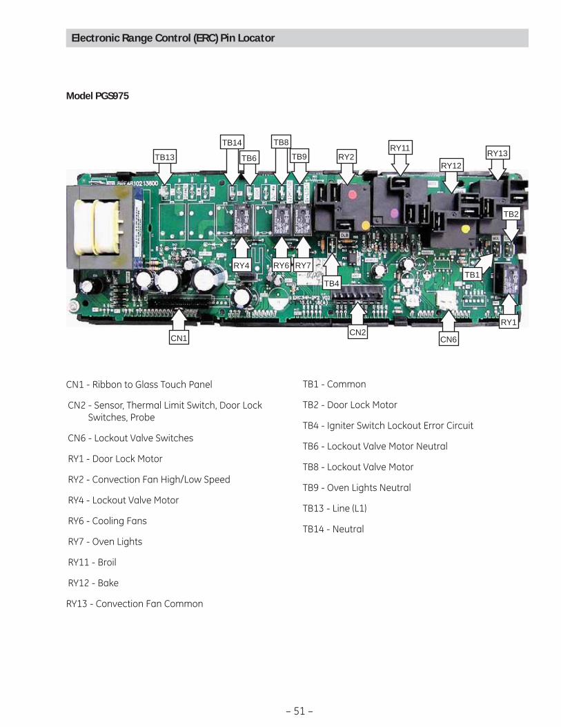
– 51 –
Electronic Range Control (ERC) Pin Locator
Model PGS975
CN2
RY2 RY13RY12
RY11
CN6CN1
TB13 TB6 TB9
TB14 TB8
TB4
TB2
TB1RY4 RY6 RY7
RY1
CN1 - Ribbon to Glass Touch Panel
CN2 - Sensor, Thermal Limit Switch, Door Lock Switches, Probe
CN6 - Lockout Valve Switches
RY1 - Door Lock Motor
RY2 - Convection Fan High/Low Speed
RY4 - Lockout Valve Motor
RY6 - Cooling Fans
RY7 - Oven Lights
RY11 - Broil
RY12 - Bake
RY13 - Convection Fan Common
TB1 - Common
TB2 - Door Lock Motor
TB4 - Igniter Switch Lockout Error Circuit
TB6 - Lockout Valve Motor Neutral
TB8 - Lockout Valve Motor
TB9 - Oven Lights Neutral
TB13 - Line (L1)
TB14 - Neutral
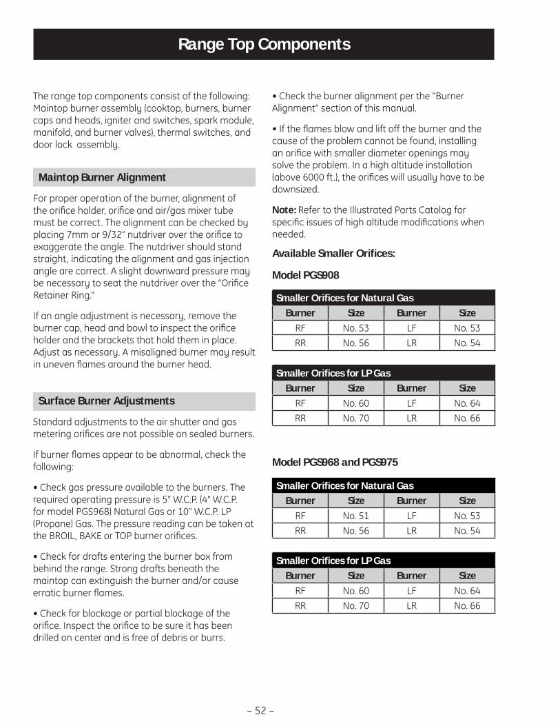
– 52 –
Range Top Components
The range top components consist of the following: Maintop burner assembly (cooktop, burners, burner caps and heads, igniter and switches, spark module, manifold, and burner valves), thermal switches, and door lock assembly.
Maintop Burner Alignment
For proper operation of the burner, alignment of the orifi ce holder, orifi ce and air/gas mixer tube must be correct. The alignment can be checked by placing 7mm or 9/32” nutdriver over the orifi ce to exaggerate the angle. The nutdriver should stand straight, indicating the alignment and gas injection angle are correct. A slight downward pressure may be necessary to seat the nutdriver over the “Orifi ce Retainer Ring.”
If an angle adjustment is necessary, remove the burner cap, head and bowl to inspect the orifi ce holder and the brackets that hold them in place. Adjust as necessary. A misaligned burner may result in uneven fl ames around the burner head.
Surface Burner Adjustments
Standard adjustments to the air shutter and gas metering orifi ces are not possible on sealed burners.
If burner fl ames appear to be abnormal, check the following:
• Check gas pressure available to the burners. The required operating pressure is 5” W.C.P. (4" W.C.P. for model PGS968) Natural Gas or 10” W.C.P. LP (Propane) Gas. The pressure reading can be taken at the BROIL, BAKE or TOP burner orifi ces.
• Check for drafts entering the burner box from behind the range. Strong drafts beneath the maintop can extinguish the burner and/or cause erratic burner fl ames.
• Check for blockage or partial blockage of the orifi ce. Inspect the orifi ce to be sure it has been drilled on center and is free of debris or burrs.
• Check the burner alignment per the “Burner Alignment” section of this manual.
• If the fl ames blow and lift off the burner and the cause of the problem cannot be found, installing an orifi ce with smaller diameter openings may solve the problem. In a high altitude installation (above 6000 ft.), the orifi ces will usually have to be downsized.
Note: Refer to the Illustrated Parts Catolog for specifi c issues of high altitude modifi cations when needed.
Smaller Orifi ces for Natural Gas Burner Size Burner Size
RF No. 51 LF No. 53RR No. 56 LR No. 54
Available Smaller Orifi ces:
Model PGS908
Smaller Orifi ces for LP GasBurner Size Burner Size
RF No. 60 LF No. 64RR No. 70 LR No. 66
Smaller Orifi ces for Natural Gas Burner Size Burner Size
RF No. 53 LF No. 53RR No. 56 LR No. 54
Model PGS968 and PGS975
Smaller Orifi ces for LP GasBurner Size Burner Size
RF No. 60 LF No. 64RR No. 70 LR No. 66
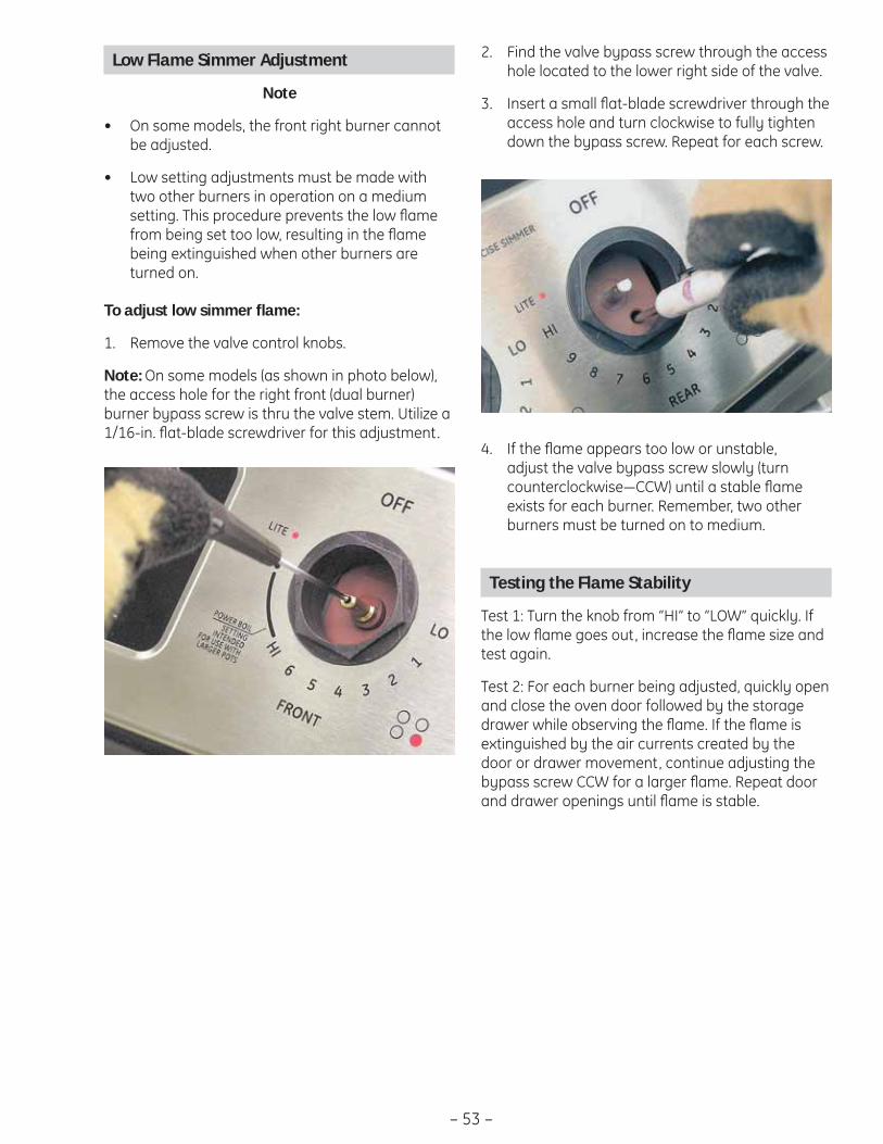
– 53 –
Low Flame Simmer Adjustment
Note
On some models, the front right burner cannot • be adjusted.
Low setting adjustments must be made with • two other burners in operation on a medium setting. This procedure prevents the low fl ame from being set too low, resulting in the fl ame being extinguished when other burners are turned on.
To adjust low simmer fl ame:
Remove the valve control knobs.1.
Note: On some models (as shown in photo below), the access hole for the right front (dual burner) burner bypass screw is thru the valve stem. Utilize a 1/16-in. fl at-blade screwdriver for this adjustment.
Find the valve bypass screw through the access 2. hole located to the lower right side of the valve.
Insert a small fl at-blade screwdriver through the 3. access hole and turn clockwise to fully tighten down the bypass screw. Repeat for each screw.
If the fl ame appears too low or unstable, 4. adjust the valve bypass screw slowly (turn counterclockwise―CCW) until a stable fl ame exists for each burner. Remember, two other burners must be turned on to medium.
Testing the Flame Stability
Test 1: Turn the knob from “HI” to “LOW” quickly. If the low fl ame goes out, increase the fl ame size and test again.
Test 2: For each burner being adjusted, quickly open and close the oven door followed by the storage drawer while observing the fl ame. If the fl ame is extinguished by the air currents created by the door or drawer movement, continue adjusting the bypass screw CCW for a larger fl ame. Repeat door and drawer openings until fl ame is stable.
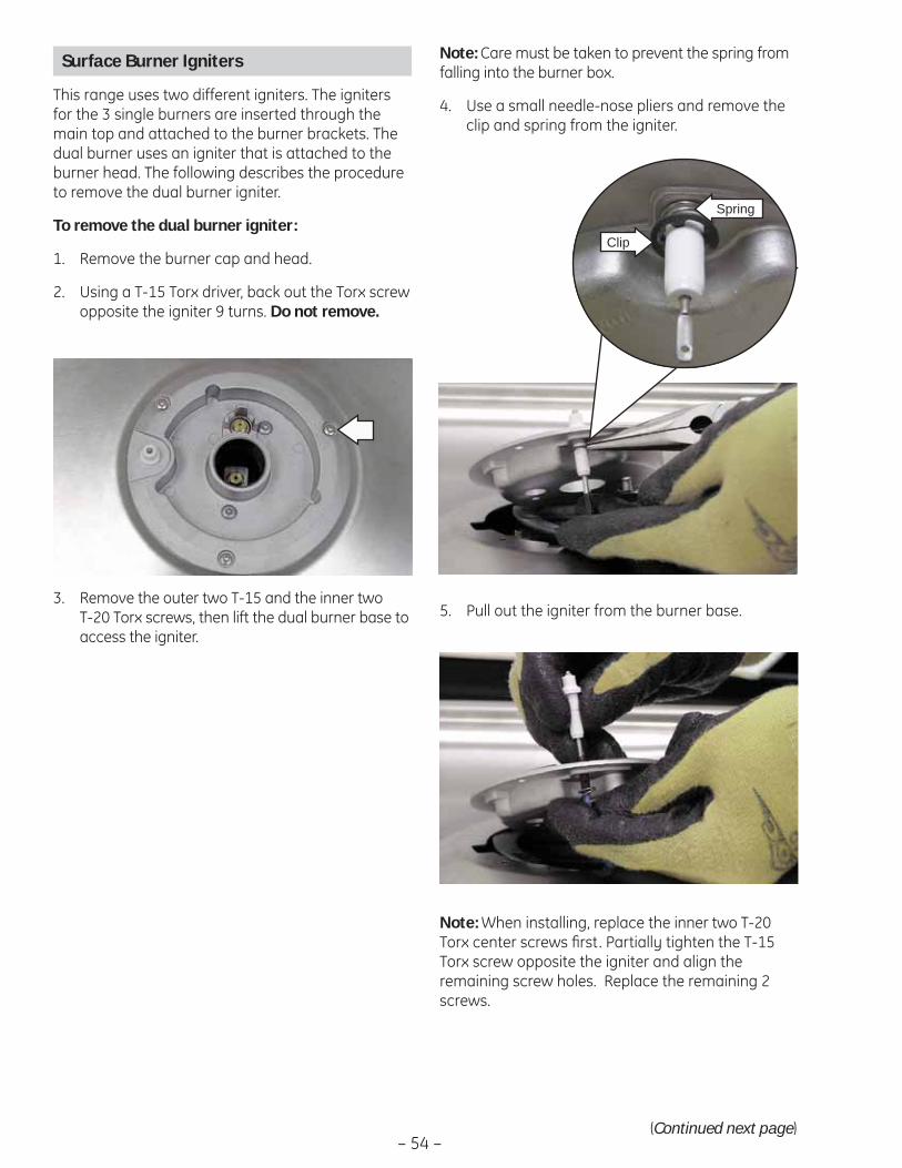
– 54 –
Note: Care must be taken to prevent the spring from falling into the burner box.
Use a small needle-nose pliers and remove the 4. clip and spring from the igniter.
Clip
Spring
Pull out the igniter from the burner base.5.
Note: When installing, replace the inner two T-20 Torx center screws fi rst. Partially tighten the T-15 Torx screw opposite the igniter and align the remaining screw holes. Replace the remaining 2 screws.
Surface Burner Igniters
This range uses two different igniters. The igniters for the 3 single burners are inserted through the main top and attached to the burner brackets. The dual burner uses an igniter that is attached to the burner head. The following describes the procedure to remove the dual burner igniter.
To remove the dual burner igniter:
Remove the burner cap and head.1.
Using a T-15 Torx driver, back out the Torx screw 2. opposite the igniter 9 turns. Do not remove.
Remove the outer two T-15 and the inner two 3. T-20 Torx screws, then lift the dual burner base to access the igniter.
(Continued next page)
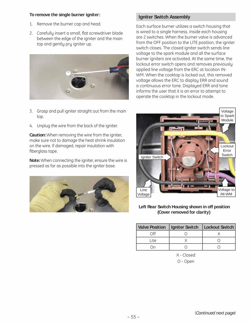
– 55 –
To remove the single burner igniter:
Remove the burner cap and head.1.
Carefully insert a small, fl at screwdriver blade 2. between the edge of the igniter and the main top and gently pry igniter up.
Grasp and pull igniter straight out from the main 3. top.
Unplug the wire from the back of the igniter.4.
Caution: When removing the wire from the igniter, make sure not to damage the heat shrink insulation on the wire. If damaged, repair insulation with fi berglass tape.
Note: When connecting the igniter, ensure the wire is pressed as far as possible into the igniter base.
Igniter Switch Assembly
Each surface burner utilizes a switch housing that is wired to a single harness. Inside each housing are 2 switches. When the burner valve is advanced from the OFF position to the LITE position, the igniter switch closes. The closed igniter switch sends line voltage to the spark module and all the surface burner igniters are activated. At the same time, the lockout error switch opens and removes previously applied line voltage from the ERC at location IN-WM. When the cooktop is locked out, this removed voltage allows the ERC to display ERR and sound a continuous error tone. Displayed ERR and tone informs the user that it is an error to attempt to operate the cooktop in the lockout mode.
Left Rear Switch Housing shown in off position (Cover removed for clarity)
Igniter Switch
Lockout Error
Switch
Voltage to Spark Module
Voltage to IM-WM
Line Voltage
Valve Position Igniter Switch Lockout SwitchOff O XLite X OOn O O
X - ClosedO - Open
(Continued next page)

– 56 –(Continued next page)
Burner Valves
Note: The following describes the procedure to remove a single burner valve. The procedure to remove the dual burner valve is similar.
To remove the single burner valve:
Remove the control panel. (See 1. Touch Panel and ERC.)
Open the oven door.2.
Remove the fi ve3. 1/4-in. hex-head screws holding the control panel frame to the maintop baffl e then remove the control panel frame.
Lift each igniter switch from the burner valve 4. stem and remove the igniter switch assembly.
Note: The bottom of each switch is molded to conform to the top of the valve for a locked-in fi t . For proper igniter operation, each switch must be locked in to the top of the valve. When installing the igniter switch assembly, align each switch to the valve stem and body then push the switch down fi rmly.
Harness
The switch housings and harness are replaced as one assembly.
To remove the igniter switch assembly:
Remove the control panel. (See 1. Touch Panel and ERC.)
Remove the 2 plastic wire ties that hold the 2. switch harness to the manifold.
Disconnect the igniter switch harness.3.
Igniter Switch Assembly Test
To test the igniter switch assembly, place the control panel in the service position. (See Touch Panel and ERC.)
Disconnect the igniter switch assembly harness. On the switch harness connector check for continuity.
Valve Position Wire Color ContinuityOff Purple to Black 0 ΩLite Purple to Black OpenOn Purple to Black OpenOff Black to Yellow OpenLite Black to Yellow 0 ΩOn Black to Yellow Open
Lift the igniter switch from the burner valve 4. stem. (See Igniter Switch Assembly.)
Remove the 9/16-in. nut and separate the 5. burner tube from the burner valve.
Remove the two 1/4-in. hex-head screws, 6. ground wire, and bracket that hold the burner valve to the manifold.
Ground Wire
Bracket
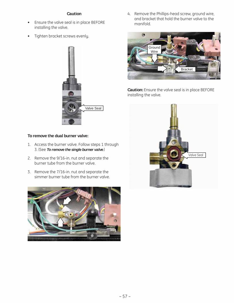
– 57 –
Caution
Ensure the valve seal is in place BEFORE • installing the valve.
Tighten bracket screws evenly.•
Valve Seal
To remove the dual burner valve:
Access the burner valve. Follow steps 1 through 1. 3. (See To remove the single burner valve.)
Remove the 9/16-in. nut and separate the 2. burner tube from the burner valve.
Remove the 7/16-in. nut and separate the 3. simmer burner tube from the burner valve.
Caution: Ensure the valve seal is in place BEFORE installing the valve.
Remove the Phillips-head screw, ground wire, 4. and bracket that hold the burner valve to the manifold.
Valve Seal
Ground Wire
Bracket
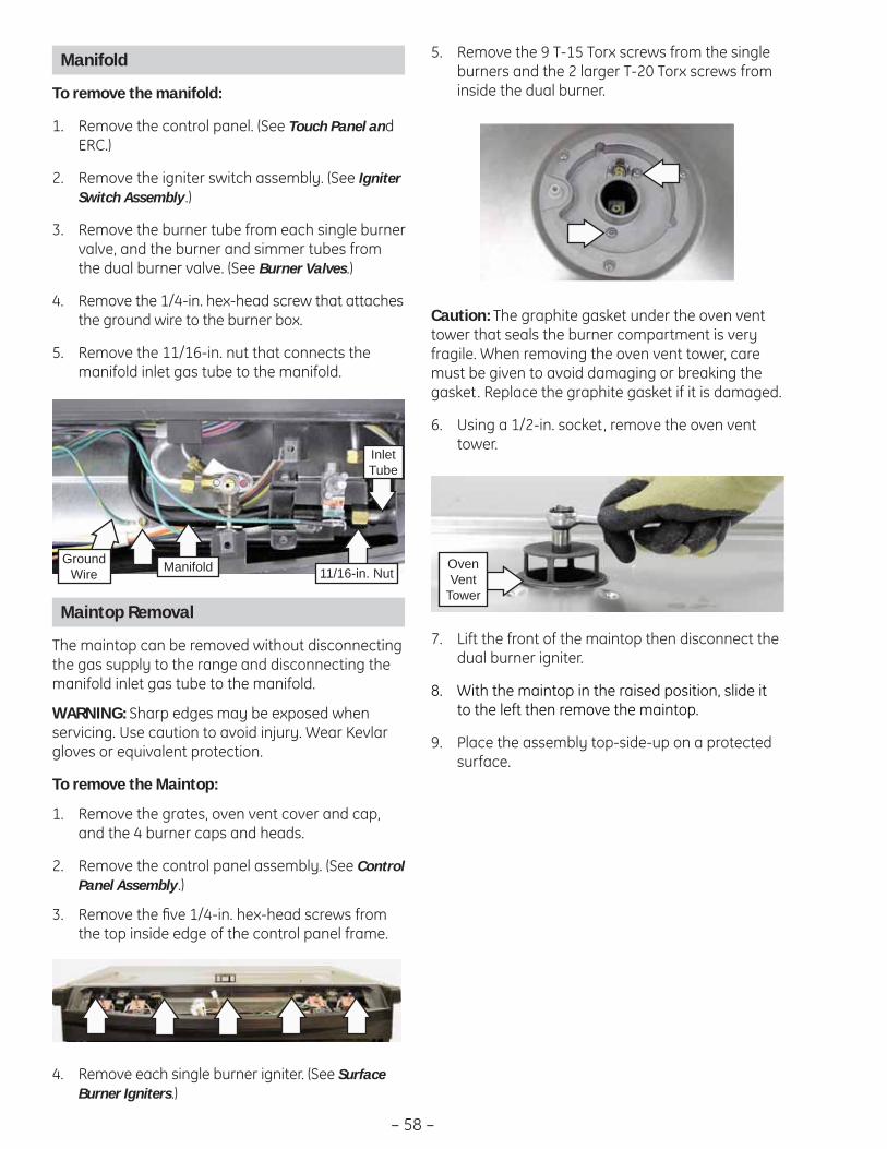
– 58 –
Maintop Removal
The maintop can be removed without disconnecting the gas supply to the range and disconnecting the manifold inlet gas tube to the manifold.
WARNING: Sharp edges may be exposed when servicing. Use caution to avoid injury. Wear Kevlar gloves or equivalent protection.
To remove the Maintop:
Remove the grates, oven vent cover and cap, 1. and the 4 burner caps and heads.
Remove the control panel assembly. (See 2. Control Panel Assembly.)
Remove the fi ve 1/4-in. hex-head screws from 3. the top inside edge of the control panel frame.
Remove each single burner igniter. (See 4. Surface Burner Igniters.)
Manifold
To remove the manifold:
Remove the control panel. (See 1. Touch Panel and ERC.)
Remove the igniter switch assembly. (See 2. Igniter Switch Assembly.)
Remove the burner tube from each single burner 3. valve, and the burner and simmer tubes from the dual burner valve. (See Burner Valves.)
Remove the 1/4-in. hex-head screw that attaches 4. the ground wire to the burner box.
Remove the 11/16-in. nut that connects the 5. manifold inlet gas tube to the manifold.
ManifoldGround Wire 11/16-in. Nut
Inlet Tube
Caution: The graphite gasket under the oven vent tower that seals the burner compartment is very fragile. When removing the oven vent tower, care must be given to avoid damaging or breaking the gasket. Replace the graphite gasket if it is damaged.
Using a 1/2-in. socket, remove the oven vent 6. tower.
Remove the 9 T-15 Torx screws from the single 5. burners and the 2 larger T-20 Torx screws from inside the dual burner.
Oven Vent
Tower
Lift the front of the maintop then disconnect the 7. dual burner igniter.
With the maintop in the raised position, slide it 8. to the left then remove the maintop.
Place the assembly top-side-up on a protected 9. surface.

– 59 –
Remove the fi ve 1/4-in. hex-head screws holding 5. the control panel frame to the maintop baffl e, then remove the control panel frame.
Maintop Burner Assembly Removal
The maintop, burners, igniters, igniter switch as-sembly, and manifold and valves, can be removed as an assembly. Removing the assembly will require disconnecting the manifold inlet gas tube from the manifold.
WARNING
Disconnect electrical power to the range • and turn OFF gas at the main valve before performing any removal procedures.
Sharp edges may be exposed when servicing. • Use caution to avoid injury. Wear Kevlar gloves or equivalent protection.
To remove the Maintop Burner Assembly:
Remove the grates, oven vent cover and cap, 1. and the 4 burner caps and heads.
Remove the oven vent tower. (See 2. Maintop Re-moval.)
Remove the control panel assembly. (See 3. Control Panel Assembly.)
Remove the fi ve 1/4-in. hex-head screws from 4. the top inside edge of the control panel frame.
(Continued next page)
Remove the 1/4-in. hex-head screw that 6. attaches the ground wire to the burner box and disconnect the igniter wire harness.
Remove the 11/16-in. nut that connects the 7. manifold inlet gas tube to the manifold.
Harness
11/16-in. nut
Raise the front of the maintop burner assembly, 8. slide it to the left. Disconnect the spark module wire harness. (See Component Locator Views.)
Remove the assembly and place it top-side-9. down on a protected surface.
Spark Module
The spark module receives line voltage when a surface burner knob is placed in the LITE position. The line voltage input to the spark module can be checked on the ERC.
To test for line voltage to the spark module:
Place the control panel in the service position. 1. (See Touch Panel and ERC.)
Carefully reinstall the glass touch panel and 2. connect the ribbon connector.
Connect power to the range. 3.
Lock out the surface burners (See4. Control Features.) or turn off the gas supply.
With a burner knob turned to the LITE position, 5. test for line voltage (120 Volts) from the yellow wire at the switch harness to N (neutral) on the ERC.
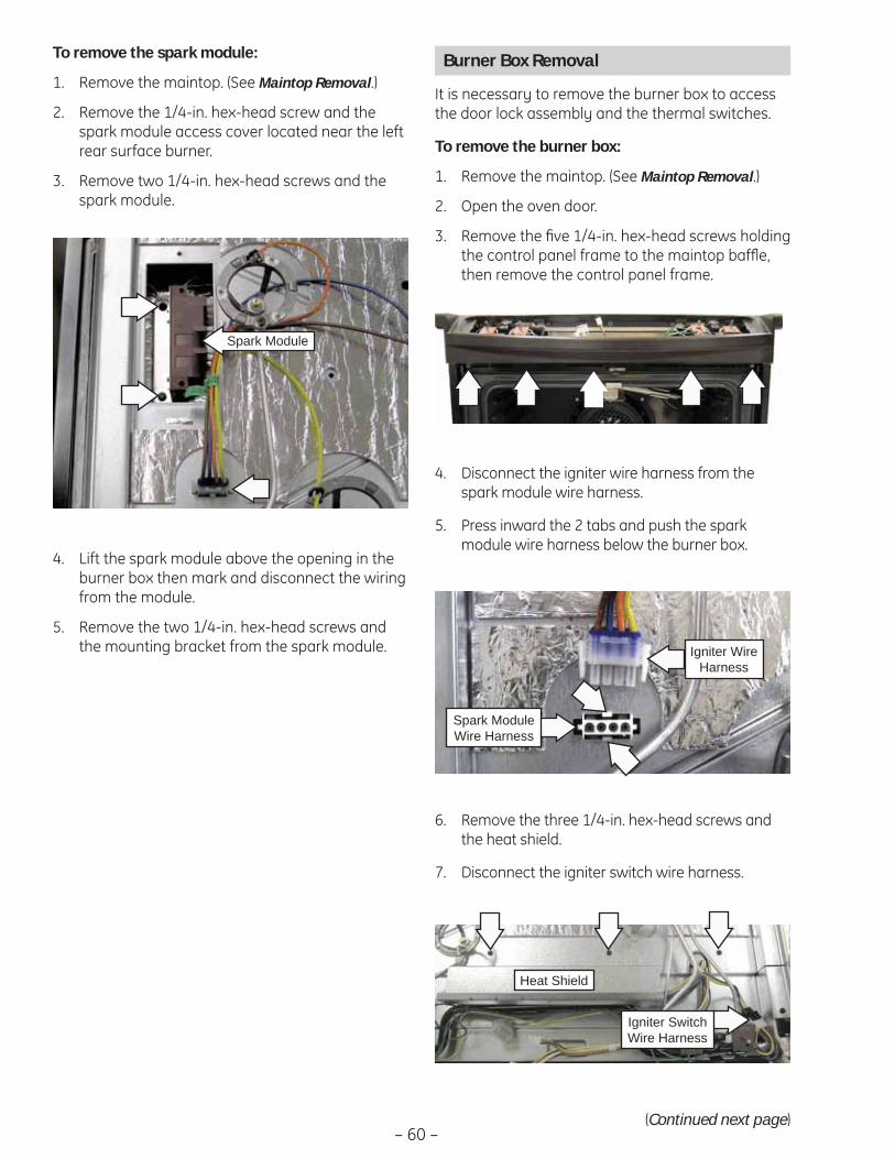
– 60 –
Lift the spark module above the opening in the 4. burner box then mark and disconnect the wiring from the module.
Remove the two 1/4-in. hex-head screws and 5. the mounting bracket from the spark module.
To remove the spark module:
Remove the maintop. (See 1. Maintop Removal.)
Remove the 1/4-in. hex-head screw and the 2. spark module access cover located near the left rear surface burner.
Remove two 1/4-in. hex-head screws and the 3. spark module.
Spark Module
Burner Box Removal
It is necessary to remove the burner box to access the door lock assembly and the thermal switches.
To remove the burner box:
Remove the maintop. (See 1. Maintop Removal.)
Open the oven door.2.
Remove the fi ve 1/4-in. hex-head screws holding 3. the control panel frame to the maintop baffl e, then remove the control panel frame.
Disconnect the igniter wire harness from the 4. spark module wire harness.
Press inward the 2 tabs and push the spark 5. module wire harness below the burner box.
Remove the three 1/4-in. hex-head screws and 6. the heat shield.
Disconnect the igniter switch wire harness.7.
Spark Module Wire Harness
Igniter Wire Harness
Heat Shield
Igniter Switch Wire Harness
(Continued next page)
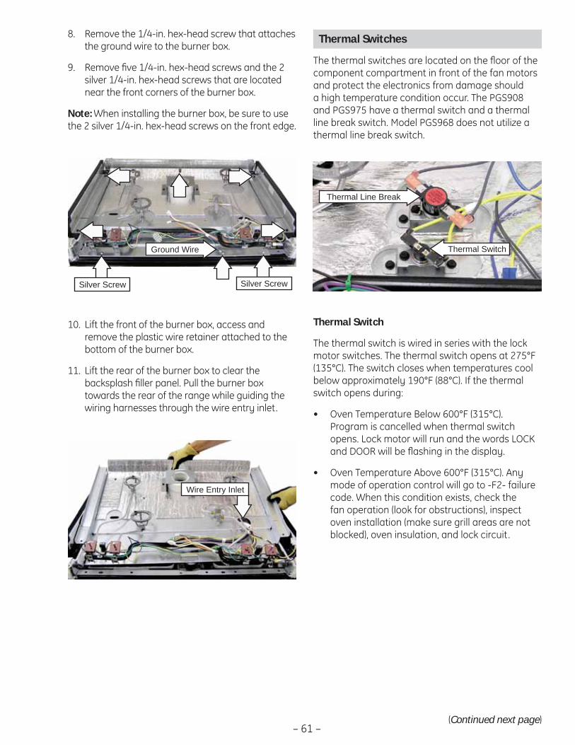
– 61 –(Continued next page)
Remove the 1/4-in. hex-head screw that attaches 8. the ground wire to the burner box.
Remove fi ve 1/4-in. hex-head screws and the 2 9. silver 1/4-in. hex-head screws that are located near the front corners of the burner box.
Note: When installing the burner box, be sure to use the 2 silver 1/4-in. hex-head screws on the front edge.
Lift the front of the burner box, access and 10. remove the plastic wire retainer attached to the bottom of the burner box.
Lift the rear of the burner box to clear the 11. backsplash fi ller panel. Pull the burner box towards the rear of the range while guiding the wiring harnesses through the wire entry inlet.
Silver Screw Silver Screw
Ground Wire
Wire Entry Inlet
Thermal Switches
The thermal switches are located on the fl oor of the component compartment in front of the fan motors and protect the electronics from damage should a high temperature condition occur. The PGS908 and PGS975 have a thermal switch and a thermal line break switch. Model PGS968 does not utilize a thermal line break switch.
Thermal Line Break
Thermal Switch
The thermal switch is wired in series with the lock motor switches. The thermal switch opens at 275°F (135°C). The switch closes when temperatures cool below approximately 190°F (88°C). If the thermal switch opens during:
Oven Temperature Below 600°F (315°C). • Program is cancelled when thermal switch opens. Lock motor will run and the words LOCK and DOOR will be fl ashing in the display.
Oven Temperature Above 600°F (315°C). Any • mode of operation control will go to -F2- failure code. When this condition exists, check the fan operation (look for obstructions), inspect oven installation (make sure grill areas are not blocked), oven insulation, and lock circuit.
Thermal Switch

– 62 –
The thermal switch has a resistance value of 0 Ω below approximately 190°F (88°C).
The resistance of the thermal switch can be checked on the ERC. Place the control panel in the service position. (See Touch Panel and ERC.)
PGS908-Test at location J1J1 pin 3 to pin 2 (door locked) or pin 3 to pin 1 (door unlocked), for 0 Ω.
PGS968 and PGS975-Test at location CN2 pin 5 to pin 4 (door locked) or pin 5 to pin 3 (door unlocked), for 0 Ω.
Thermal Line Break Switch
The thermal line break switch disconnects power to all range components when an over-temperature condition exists in the burner box. The thermal line break switch will open at 250°F and is not resetable. Determine the cause of the over-temperature condition before replacing the open thermal line break switch.
The thermal line break switch has a resistance value of 0 Ω below approximately 250°F (121°C).
The resistance of the thermal line break switch can be checked on the ERC. Place the control panel in the service position. (See Touch Panel and ERC.)
PGS908 - Test at location L1 to the non-ribbed (line) side of the power cord for 0 Ω.
PGS975 - Test at location COM to the non-ribbed (line) side of the power cord for 0 Ω.
To remove the thermal switches:
Remove the maintop burner assembly (see 1. Maintop Burner Assembly).
Note the placement of the wiring to the thermal 2. switch that is being removed. Disconnect the wiring.
Remove the 2 hex-head screws that hold the 3. thermal switch in place.
Remove the thermal switch. 4.
Door Lock Assembly
The door lock assembly consists of a lock motor cam and switch assembly, lock hook, and mounting plate.
The lock motor is energized when the control is set for CLEAN and CLEAN TIME is selected. The K4 relay contacts will close and complete the circuit that supplies the voltage to the lock motor.
543
6
8
DOOR UNLATCHED INPUT PINDOOR LATCHED INPUT PIN
SENSOR AND LOCKSWITCH CONNECTORS
UNLOCK SW. #2UNLOCK SW. #2
LOCKSW. #1
LOCK SW. CIRCUITUNLOCKED
DOOR LATCH OUTPUT PIN 5, -25V DC
543
6
8
DOOR LATCH OUTPUT PIN 5, -25V DC
DOOR UNLATCHED INPUT PINDOOR LATCHED INPUT PIN
SENSOR AND LOCKSWITCH CONNECTORS
UNLOCK SW. #2
LOCKSW. #1
LOCK SW. CIRCUITLOCKED
THERMAL SWITCH
THERMAL SWITCH
PGS968 and PGS975
PGS908
3
2
1
5
7
DOOR LATCH OUTPUT PIN 5, -25VDCAT ALL TIMES MEASURED TO GROUND
DOOR UNLATCHED INPUT PIN
DOOR LATCHED INPUT PIN
SENSOR AND LOCKSWITCH CONNECTORS
UNLOCK SW. #2
LOCKSW. #1
LOCK SW. CIRCUIT
LOCKED
3
2
1
5
7
DOOR LATCH OUTPUT PIN 5, -25VDCAT ALL TIMES MEASURED TO GROUND
DOOR UNLATCHED INPUT PIN
DOOR LATCHED INPUT PIN
SENSOR AND LOCKSWITCH CONNECTORS
UNLOCK SW. #2
LOCKSW. #1
LOCK SW. CIRCUIT
UNLOCKED
THERMAL SWITCH
THERMAL SWITCH
(Continued next page)
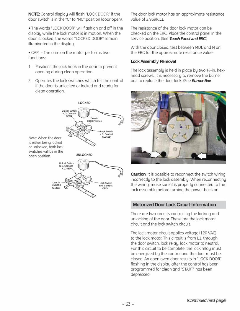
– 63 –
NOTE: Control display will fl ash “LOCK DOOR” if the door switch is in the “C” to “NC” position (door open).
• The words “LOCK DOOR” will fl ash on and off in the display while the lock motor is in motion. When the door is locked, the words “LOCKED DOOR” remain illuminated in the display.
• CAM – The cam on the motor performs two functions:
Positions the lock hook in the door to prevent 1. opening during clean operation.
Operates the lock switches which tell the control 2. if the door is unlocked or locked and ready for clean operation.
HTIHTI Tech & Ind
HTSYG048B002FL45
-0001Date:Made in China
Lock SwitchN.O. Contact
CLOSED
Cam inLOCK Position
LOCKED
Unlock SwitchN.O. Contact
OPEN
HTIHTI Tech & Ind
HTSYG048B002FL45
-0001Date:Made in China
Lock SwitchN.O. Contact
OPEN
Unlock SwitchN.O. Contact
CLOSED
Cam inUNLOCK Position
UNLOCKED
Note: When the door is either being locked or unlocked, both lock switches will be in the open position.
Caution: It is possible to reconnect the switch wiring incorrectly to the lock assembly. When reconnecting the wiring, make sure it is properly connected to the lock assembly before turning the power back on.
Motorized Door Lock Circuit Information
There are two circuits controlling the locking and unlocking of the door. These are the lock motor circuit and the lock switch circuit.
The lock motor circuit applies voltage (120 VAC) to the lock motor. This circuit is from L1, through the door switch, lock relay, lock motor to neutral. For this circuit to be complete, the lock relay must be energized by the control and the door must be closed. An open oven door results in “LOCK DOOR” fl ashing in the display after the control has been programmed for clean and “START” has been depressed.
The door lock motor has an approximate resistance value of 2.969K Ω.
The resistance of the door lock motor can be checked on the ERC. Place the control panel in the service position. (See Touch Panel and ERC.)
With the door closed, test between MDL and N on the ERC for the approximate resistance value.
Lock Assembly Removal
The lock assembly is held in place by two ¼-in. hex-head screws. It is necessary to remove the burner box to replace the door lock. (See Burner Box.)
(Continued next page)
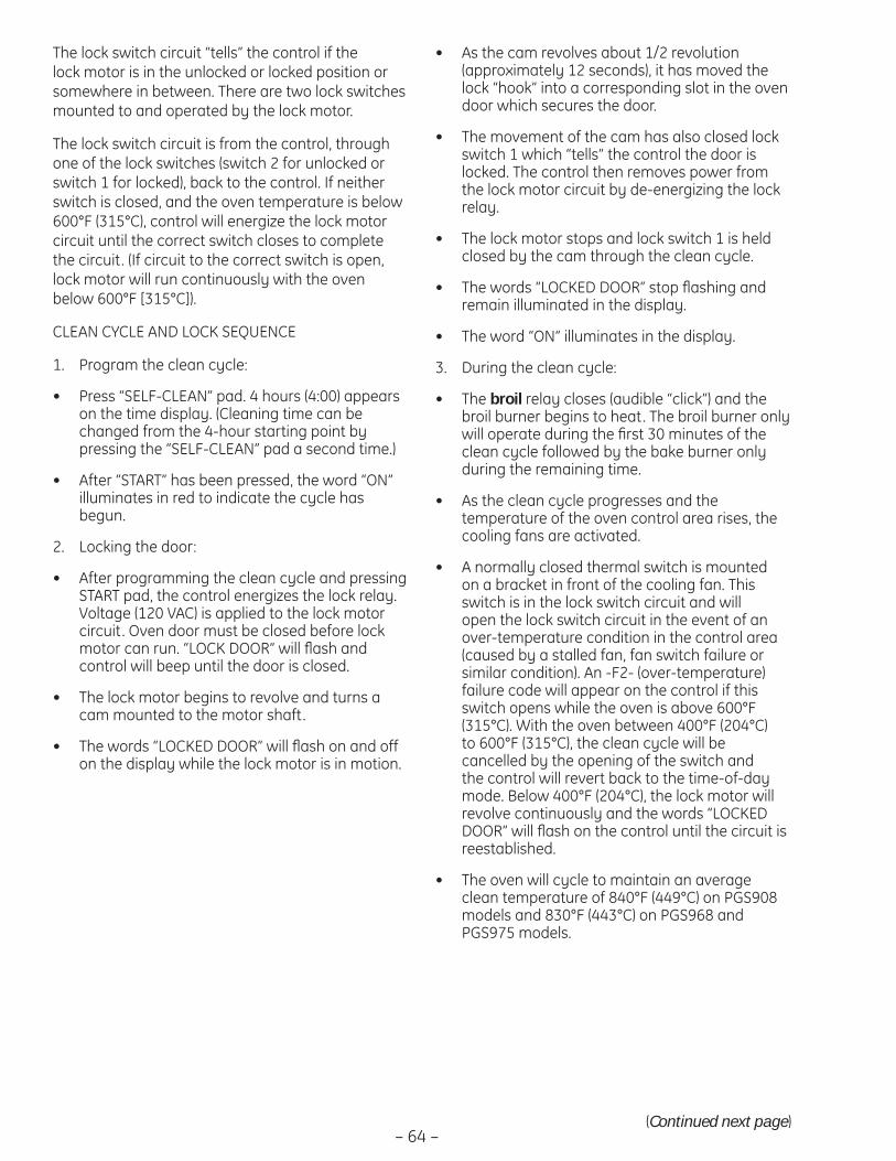
– 64 –(Continued next page)
The lock switch circuit “tells” the control if the lock motor is in the unlocked or locked position or somewhere in between. There are two lock switches mounted to and operated by the lock motor.
The lock switch circuit is from the control, through one of the lock switches (switch 2 for unlocked or switch 1 for locked), back to the control. If neither switch is closed, and the oven temperature is below 600°F (315°C), control will energize the lock motor circuit until the correct switch closes to complete the circuit. (If circuit to the correct switch is open, lock motor will run continuously with the oven below 600°F [315°C]).
CLEAN CYCLE AND LOCK SEQUENCE
Program the clean cycle:1.
Press “SELF-CLEAN” pad. 4 hours (4:00) appears • on the time display. (Cleaning time can be changed from the 4-hour starting point by pressing the “SELF-CLEAN” pad a second time.)
After “START” has been pressed, the word “ON” • illuminates in red to indicate the cycle has begun.
Locking the door:2.
After programming the clean cycle and pressing • START pad, the control energizes the lock relay. Voltage (120 VAC) is applied to the lock motor circuit. Oven door must be closed before lock motor can run. “LOCK DOOR” will fl ash and control will beep until the door is closed.
The lock motor begins to revolve and turns a • cam mounted to the motor shaft.
The words “LOCKED DOOR” will fl ash on and off • on the display while the lock motor is in motion.
As the cam revolves about 1/2 revolution • (approximately 12 seconds), it has moved the lock “hook” into a corresponding slot in the oven door which secures the door.
The movement of the cam has also closed lock • switch 1 which “tells” the control the door is locked. The control then removes power from the lock motor circuit by de-energizing the lock relay.
The lock motor stops and lock switch 1 is held • closed by the cam through the clean cycle.
The words “LOCKED DOOR” stop fl ashing and • remain illuminated in the display.
The word “ON” illuminates in the display.•
During the clean cycle:3.
The • broil relay closes (audible “click”) and the broil burner begins to heat. The broil burner only will operate during the fi rst 30 minutes of the clean cycle followed by the bake burner only during the remaining time.
As the clean cycle progresses and the • temperature of the oven control area rises, the cooling fans are activated.
A normally closed thermal switch is mounted • on a bracket in front of the cooling fan. This switch is in the lock switch circuit and will open the lock switch circuit in the event of an over-temperature condition in the control area (caused by a stalled fan, fan switch failure or similar condition). An -F2- (over-temperature) failure code will appear on the control if this switch opens while the oven is above 600°F (315°C). With the oven between 400°F (204°C) to 600°F (315°C), the clean cycle will be cancelled by the opening of the switch and the control will revert back to the time-of-day mode. Below 400°F (204°C), the lock motor will revolve continuously and the words “LOCKED DOOR” will fl ash on the control until the circuit is reestablished.
The oven will cycle to maintain an average • clean temperature of 840°F (449°C) on PGS908 models and 830°F (443°C) on PGS968 and PGS975 models.
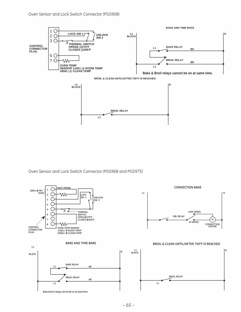
– 65 –
Oven Sensor and Lock Switch Connector (PGS908)
Oven Sensor and Lock Switch Connector (PGS968 and PGS975)
L1
BLACKN
L1
BAKE AND TIME BAKE
BAKE RELAY
BROIL RELAY
L1
BR
BK
L1BLACK
N
BROIL & CLEAN UNTIL/AFTER 750°F IS REACHED
BROIL RELAY
L1
Bake & Broil relays cannot be on at same time.
L1 N
CONVECTION BAKE
DBL RELAY
LOW SPEED
HI SPEEDM
CONVECTIONMOTOR
1
2
3
4
5
6
7
8OVEN TEMP SENSOR1100Ω @ ROOM TEMP2650Ω
@ CLEAN TEMP
UNLOCKSW. 2
LOCKSW. 1
MEAT PROBE 50KΩ @ RM
CONTROLCONNECTORPLUG
THERMALSWITCHOPEN @275°FCLOSES @205°F
TEMP
L1BLACK
N
L1
BAKE AND TIME BAKE
BAKE RELAY
BROIL RELAY
L1
BR
BK
L1BLACK
N
BROIL & CLEAN UNTIL/AFTER 750° F IS REACHED
BROIL RELAY
L1
Bake & Broil relays cannot be on at same time.
123
57
OVEN TEMPSENSOR 1100Ω @ ROOM TEMP2650Ω @ CLEAN TEMP
UNLOCKSW 2
LOCK SW 1
CONTROLCONNECTORPLUG
THERMAL SWITCHOPENS @275°FCLOSES @205°F

– 66 –
Diagnostics and Service Information
Problem Possible Causes What to Do
Burner fl ames are very large, yellow, or yel-low-tipped
Incorrect gas being used.
The combustion quality of burner fl ames needs to be determined visually.
• Check for correct gas supply.
• Use the illustrations below to determine if the burner fl ames are normal. If the burner fl ames look like A, check for dirty burners and orifi ces. Clean or replace. Normal burner fl ames should look like B or C, depending on the type of gas you use. With LP gas, some yellow tipping on outer cones is normal.
Regulator malfunction. • Check output gas supply.
Burners do not light Plug on cooktop is not completely inserted in the electrical outlet.
• Make sure electrical plug is plugged into a live, properly grounded outlet.
Gas supply is not connect-ed or turned ON.
• See the Installation Instructions that came with the cooktop.
A fuse may be blown or a circuit breaker tripped.
• Replace the fuse or reset the circuit breaker.
Burner parts not replaced correctly.
• Make sure pins in the burner head are properly located in the burner base holes.
Holes or slits in burners clogged.
• Clean or replace as necessary. Make sure all components are dry before reassembly.
Liquid in burner base due to spillage.
• Remove burner ring to check. Clean and dry thor-oughly before reassembly.
Orifi ces plugged or dirty. • Clean or replace as necessary.
Igniter switch defective. • Replace igniter switches.
Igniter wire defective. • Connect igniter wire.
Spark module defective. • Replace spark module.
Burner control knob will not turn
Knob is in the OFF position. • The knob must be pushed in before it can be turned; it can only be turned in a counterclock-wise direction.
Ticking sound of spark igniter persists after burner lights
Improper fl ame sensing. • Check for wrong igniter wiring.• Replace the igniter.
Ticking sound persists after burner is turned OFF
Be sure the knob is in the OFF position.
• Remove knob and check the bottom of knob for buildup of soil. If ticking persists, replace igniter switches.
A–Yellow fl ames: Call for service
B–Yellow tips on outer cones: Normal for LP gas
C–Soft blue fl ames: Normal for natural gas
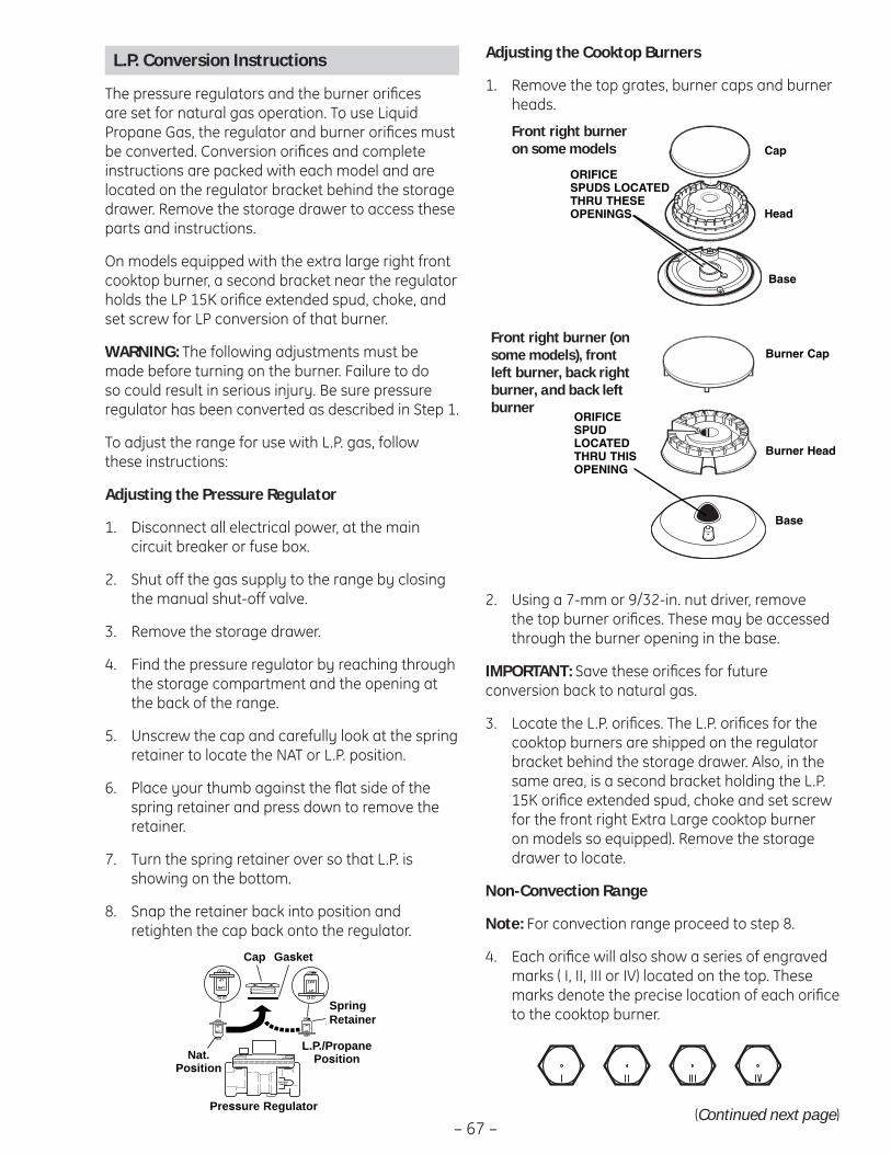
– 67 –
L.P. Conversion Instructions
The pressure regulators and the burner orifi ces are set for natural gas operation. To use Liquid Propane Gas, the regulator and burner orifi ces must be converted. Conversion orifi ces and complete instructions are packed with each model and are located on the regulator bracket behind the storage drawer. Remove the storage drawer to access these parts and instructions.
On models equipped with the extra large right front cooktop burner, a second bracket near the regulator holds the LP 15K orifi ce extended spud, choke, and set screw for LP conversion of that burner.
WARNING: The following adjustments must be made before turning on the burner. Failure to do so could result in serious injury. Be sure pressure regulator has been converted as described in Step 1.
To adjust the range for use with L.P. gas, follow these instructions:
Adjusting the Pressure Regulator
Disconnect all electrical power, at the main 1. circuit breaker or fuse box.
Shut off the gas supply to the range by closing 2. the manual shut-off valve.
Remove the storage drawer.3.
Find the pressure regulator by reaching through 4. the storage compartment and the opening at the back of the range.
Unscrew the cap and carefully look at the spring 5. retainer to locate the NAT or L.P. position.
Place your thumb against the fl at side of the 6. spring retainer and press down to remove the retainer.
Turn the spring retainer over so that L.P. is 7. showing on the bottom.
Snap the retainer back into position and 8. retighten the cap back onto the regulator.
NAT.SITION
L.P./PROPANEPOSITION
CAP
SPRINRETAIN
DOWNFOR OFF
NAT
LP
LP
NAT
GASKET
PRESSURE REGULATOR
LP
NAT
NAT
LP
Cap Gasket
SpringRetainer
L.P./PropanePosition
Pressure Regulator
Nat.Position
Adjusting the Cooktop Burners
Remove the top grates, burner caps and burner 1. heads.
Using a 7-mm or 9/32-in. nut driver, remove 2. the top burner orifi ces. These may be accessed through the burner opening in the base.
IMPORTANT: Save these orifi ces for future conversion back to natural gas.
Locate the L.P. orifi ces. The L.P. orifi ces for the 3. cooktop burners are shipped on the regulator bracket behind the storage drawer. Also, in the same area, is a second bracket holding the L.P. 15K orifi ce extended spud, choke and set screw for the front right Extra Large cooktop burner on models so equipped). Remove the storage drawer to locate.
Non-Convection Range
Note: For convection range proceed to step 8.
Each orifi ce will also show a series of engraved 4. marks ( I, II, III or IV) located on the top. These marks denote the precise location of each orifi ce to the cooktop burner.
Cap
Head
Base
ORIFICESPUDS LOCATEDTHRU THESEOPENINGS
Base
ORIFICESPUDLOCATEDTHRU THISOPENING
Burner Cap
Burner Head
Front right burner on some models
Front right burner (on some models), front left burner, back right burner, and back left burner
(Continued next page)

– 68 –(Continued next page)
Install the L.P. orifi ces in their precise locations. 5. Install the extended spud on the 15K Extra Large front right burner (on models so equipped).
Note: To prevent leakage, make sure the orifi ce spuds are securely screwed into the gas supply tubes.
For the Extra Large burner (right front), the choke 6. and set screw will be needed. Insert the choke into the burner head; then insert the set screw into the burner head and tighten securely. Make sure the screw head is against the shoulder (within the choke notch) so it does not have any rotational movement.
Install the old orifi ce spuds into the metal 7. bracket and replace both metal brackets back on the range for possible future conversion.
Note: In the future, to convert back to natural gas, remove the entire L.P. extended orifi ce spud.
II
III
I
IVFront of Range
Note: On15K ExtraLarge frontright burner,use theExtendedSpud.
ExtendedSpud for
front rightExtraLargeburner
Burner Cap
Burner Head
Base
Set Screw
Choke
ORIFICE SPUDLOCATEDTHRU THISOPENING Extended Spud
Convection Range
Each orifi ce will also show a series of engraved 8. marks (I, II, III) or a number (108) located on the top. These marks and numbers denote the precise location of each orifi ce to the cooktop burner.
Install the L.P. orifi ces in their precise locations.9.
Note: On models with dual burner orifi ces, the simmer orifi ce is not changed for L.P. conversion.
IMPORTANT: Return the natural orifi ces to the bracket and reattach the bracket and these instructions to the range using the screw previously removed.
108
II
III
I
108Front of Range
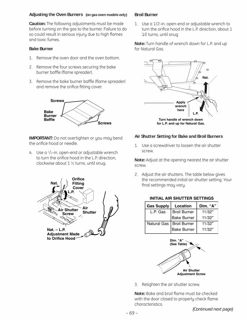
– 69 –
IMPORTANT: Do not overtighten or you may bend the orifi ce hood or needle.
Use a 4. 1/2-in. open-end or adjustable wrench to turn the orifi ce hood in the L.P. direction, clockwise about 1 1⁄2 turns, until snug.
Screws
BakeBurnerBaffle
Screws
Air ShutterScrew
Orifice FittingCover
Air Shutter
NAT. - LP. ADJUSTMENT
L.P.
NAT.
AirShutter
Nat.
Air ShutterScrew
L.P.
OrificeFittingCover
Nat. – L.P.Adjustment Madeto Orifice Hood
Adjusting the Oven Burners (on gas oven models only)
Caution: The following adjustments must be made before turning on the gas to the burner. Failure to do so could result in serious injury due to high fl ames and toxic fumes.
Bake Burner
Remove the oven door and the oven bottom.1.
Remove the four screws securing the bake 2. burner baffl e (fl ame spreader).
Remove the bake burner baffl e (fl ame spreader) 3. and remove the orifi ce fi tting cover.
(Continued next page)
Broil Burner
Use a 1/2-in. open-end or adjustable wrench to 1. turn the orifi ce hood in the L.P. direction, about 1 1⁄2 turns, until snug
Note: Turn handle of wrench down for L.P. and up for Natural Gas.
Air Shutter Setting for Bake and Broil Burners
Use a screwdriver to loosen the air shutter 1. screw.
Note: Adjust at the opening nearest the air shutter screw.
Adjust the air shutters. The table below gives 2. the recommended initial air shutter setting. Your fi nal settings may vary.
Nat.
Applywrench
hereL.P.
Turn handle of wrench down for L.P. and up for Natural Gas.
INITIAL AIR SHUTTER SETTINGS
Gas Supply Location Dim. “A”L.P. Gas Broil Burner 11/32″
Bake Burner 11/32″Natural Gas Broil Burner 11/32″
Bake Burner 11/32″
Air Shutter Adjustment Scre
Air Shutter Adjustment Screw
Dim. “A” (See Table)
Retighten the air shutter screw.3.
Note: Bake and broil fl ame must be checked with the door closed to properly check fl ame characteristics.
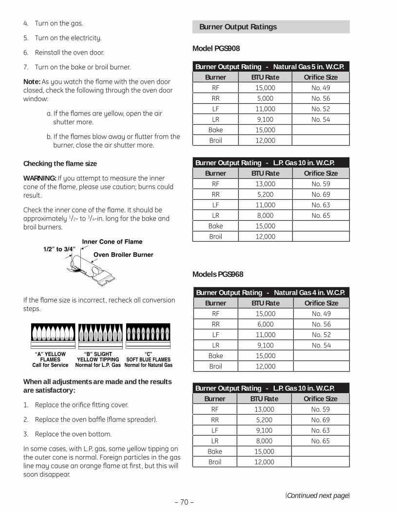
– 70 –
Checking the fl ame size
WARNING: If you attempt to measure the inner cone of the fl ame, please use caution; burns could result.
Check the inner cone of the fl ame. It should be approximately 1/2- to 3/4-in. long for the bake and broil burners.
If the fl ame size is incorrect, recheck all conversion steps.
When all adjustments are made and the results are satisfactory:
Replace the orifi ce fi tting cover.1.
Replace the oven baffl e (fl ame spreader).2.
Replace the oven bottom.3.
In some cases, with L.P. gas, some yellow tipping on the outer cone is normal. Foreign particles in the gas line may cause an orange fl ame at fi rst, but this will soon disappear.
Turn on the gas. 4.
Turn on the electricity.5.
Reinstall the oven door. 6.
Turn on the bake or broil burner. 7.
Note: As you watch the fl ame with the oven door closed, check the following through the oven door window:
a. If the fl ames are yellow, open the air shutter more.
b. If the fl ames blow away or fl utter from the burner, close the air shutter more.
1/2" TO 3/4"
DE LLAMA
QUEMADOR PARAHORNEAR/ASAR
1/2″ to 3/4″Inner Cone of Flame
Oven Broiler Burner
“A” YELLOWFLAMES
Call for Service
“B” SLIGHT YELLOW TIPPING
Normal for L.P. Gas
“C”SOFT BLUE FLAMES
Normal for Natural Gas
Burner Output Ratings
(Continued next page)
Model PGS908
Burner Output Rating - Natural Gas 5 in. W.C.P.Burner BTU Rate Orifi ce Size
RF 15,000 No. 49RR 5,000 No. 56LF 11,000 No. 52LR 9,100 No. 54
Bake 15,000Broil 12,000
Burner Output Rating - L.P. Gas 10 in. W.C.P.Burner BTU Rate Orifi ce Size
RF 13,000 No. 59RR 5,200 No. 69LF 11,000 No. 63LR 8,000 No. 65
Bake 15,000Broil 12,000
Models PGS968
Burner Output Rating - Natural Gas 4 in. W.C.P.Burner BTU Rate Orifi ce Size
RF 15,000 No. 49RR 6,000 No. 56LF 11,000 No. 52LR 9,100 No. 54
Bake 15,000Broil 12,000
Burner Output Rating - L.P. Gas 10 in. W.C.P.Burner BTU Rate Orifi ce Size
RF 13,000 No. 59RR 5,200 No. 69LF 9,100 No. 63LR 8,000 No. 65
Bake 15,000Broil 12,000
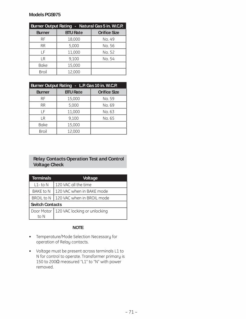
– 71 –
Models PGS975
Burner Output Rating - Natural Gas 5 in. W.C.P.Burner BTU Rate Orifi ce Size
RF 18,000 No. 49RR 5,000 No. 56LF 11,000 No. 52LR 9,100 No. 54
Bake 15,000Broil 12,000
Burner Output Rating - L.P. Gas 10 in. W.C.P.Burner BTU Rate Orifi ce Size
RF 15,000 No. 59RR 5,000 No. 69LF 11,000 No. 63LR 9,100 No. 65
Bake 15,000Broil 12,000
Relay Contacts Operation Test and Control Voltage Check
Terminals VoltageL1- to N 120 VAC all the time
BAKE to N 120 VAC when in BAKE modeBROIL to N 120 VAC when in BROIL modeSwitch ContactsDoor Motor
to N120 VAC locking or unlocking
NOTE
Temperature/Mode Selection Necessary for • operation of Relay contacts.
Voltage must be present across terminals L1 to • N for control to operate. Transformer primary is 150 to 200Ω measured “L1” to “N” with power removed.

– 72 –
Failure Code Meaning Correction-F0- Shorted OFF key
(Membrane) or GT ErrorPerform glass touch board key panel test. Determine if problem is with key panel or control by disconnecting ribbon cable and measuring fl at cable pins 13 to 14. Should be open. Should be 100-150 Ω while pressing OFF key.
-F2- Over temperatureInside oven cavity as measured by sensor over 600°F (315°C) unlatched or 915°F (491°C) latched.
Welded relay contacts• Cooling fan stalled or blocked• Airfl ow to rear of unit• High resistance in oven sensor leads/connectors (especially at • sensor rear)
-F3- Open oven sensor (under 950 Ω)
Disconnect power. Disconnect sensor harness from control. • Measure sensor resistance (white leads) to be -1080 Ω at room temperature with 2 Ω per degree change.Look for damaged harness terminals if not a bad sensor.•
-F4- Shorted oven sensor (over 2900 Ω)
Disconnect power. Disconnect sensor harness from control. • Measure sensor resistance (white leads) to be -1080 Ω at room temperature with 2 Ω per degree change.Separate sensor from harness to determine fault.•
-F7- Shorted matrix to START key
Determine if problem is with key panel or control by disconnecting ribbon cable and measuring fl at cable using pinout chart. Allow up to 1000 Ω when pressing key.
-F8- EEPROM data shift failure If repeated, replace control-F9- Cooling fan stalls while
above 650°F (343°C); open thermal switch in yellow or blue leads
Cooling fan or airfl ow to control area.
-FF- Loss of latch motor safety circuit
Replace control.
ERC Failure Codes
The ERC (electronic range control) has error (F) codes that can be utilized by the service technician in order to quickly identify failed or improper operation of certain oven components. The oven may stop operating but not give an F code on the display immediately. A fault must exist continuously for 5 minutes before an F code is recorded (F2, F8 are sooner). F codes are stored in nonvolatile EEPROM memory until the same fault occurs twice consecutively.
F codes can be recalled by pressing together TIMER, CLOCK, MIN DOWN or 9. While F codes are displayed, pressing MIN UP or 8 and HR DOWN or 6 together will clear them. To exit failure code mode, press upper oven START pad.
Note: If an "FO" failure code is displayed and the buttons do not work, disconnect power to the range. Wait 5 seconds then reconnect power to the range. Press the “Bake” and “Broil” keys simultaneously until “SF” appears in the display. (You are now in the Special Features function.) Press the “9” and “0” keys simultaneously for 5 seconds. Wait until time of day is displayed. Press “1” and “5” keys simultaneously. The display will: go blank, briefl y display all LED segments, briefl y display “Loc rEF”, display all segments for 30 seconds, and then display “LOC REF”. Then press “6” and “8” keys simultaneously and the control will display time of day. Verify control operation by pushing several keys at random to ensure they all work.
When fi rst plugged in, if all display segments illuminate for approximately 7 seconds, then Loc rEF appears in the display, and none of the pads work, proceed to step #5 then #6.
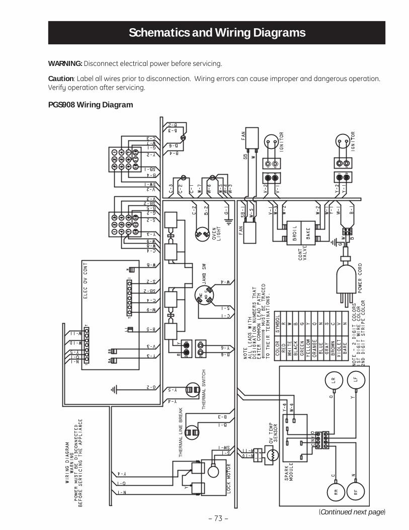
– 73 –
WARNING: Disconnect electrical power before servicing.
Caution: Label all wires prior to disconnection. Wiring errors can cause improper and dangerous operation. Verify operation after servicing.
Schematics and Wiring Diagrams
(Continued next page)
THERMAL
SWITCH
THERMAL
LINE B
REAK
PGS908 Wiring Diagram

– 74 –(Continued next page)
PGS908 Schematic

– 75 –(Continued next page)
NOTE
:RY
refe
renc
es o
n co
ntro
l may
be
diffe
rent
than
sho
wn.
THERMAL
SWITCH
LTHERMAL
SWITCH
PGS968 Wiring Diagram
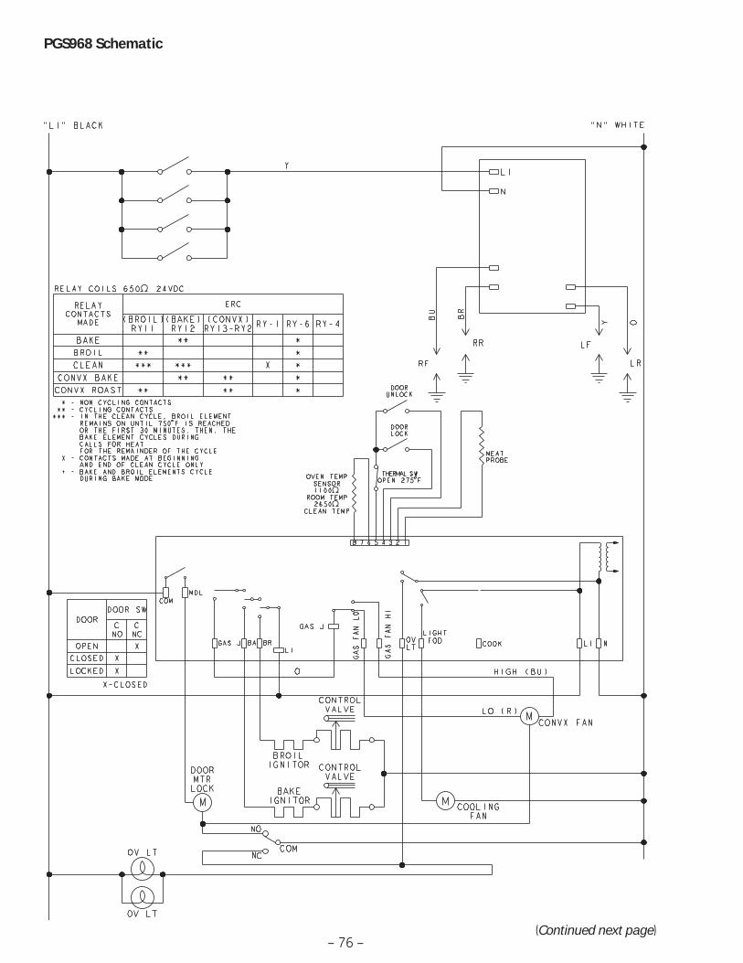
– 76 –(Continued next page)
PGS968 Schematic

– 77 –
THERMAL
SWITCH
THERMAL
LINE B
REAK
PGS975 Wiring Diagram
(Continued next page)

– 78 –
PGS975 Schematic
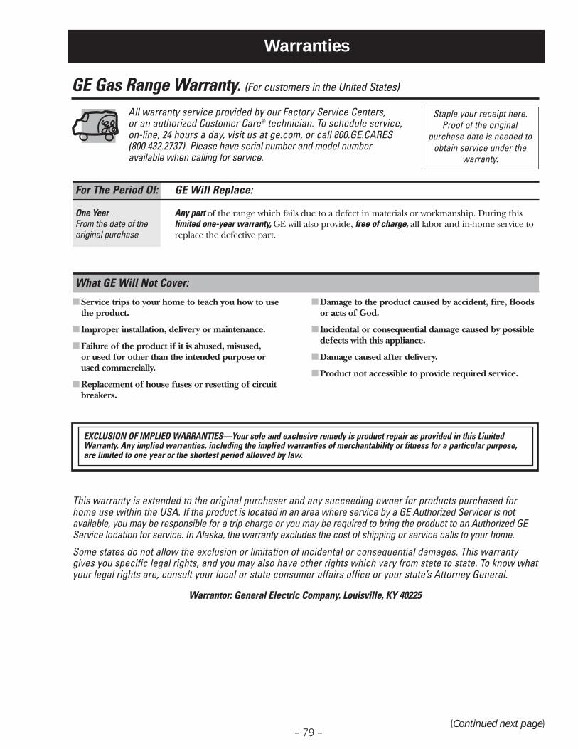
– 79 –
Warranties
■ Service trips to your home to teach you how to use the product.
■ Improper installation, delivery or maintenance.
■ Failure of the product if it is abused, misused, or used for other than the intended purpose or used commercially.
■ Replacement of house fuses or resetting of circuitbreakers.
■ Damage to the product caused by accident, fire, floods or acts of God.
■ Incidental or consequential damage caused by possibledefects with this appliance.
■ Damage caused after delivery.
■ Product not accessible to provide required service.
What GE Will Not Cover:
This warranty is extended to the original purchaser and any succeeding owner for products purchased forhome use within the USA. If the product is located in an area where service by a GE Authorized Servicer is notavailable, you may be responsible for a trip charge or you may be required to bring the product to an Authorized GEService location for service. In Alaska, the warranty excludes the cost of shipping or service calls to your home.
Some states do not allow the exclusion or limitation of incidental or consequential damages. This warrantygives you specific legal rights, and you may also have other rights which vary from state to state. To know whatyour legal rights are, consult your local or state consumer affairs office or your state’s Attorney General.
Warrantor: General Electric Company. Louisville, KY 40225
For The Period Of: GE Will Replace:
One Year Any part of the range which fails due to a defect in materials or workmanship. During thisFrom the date of the limited one-year warranty, GE will also provide, free of charge, all labor and in-home service tooriginal purchase replace the defective part.
GE Gas Range Warranty. (For customers in the United States)
All warranty service provided by our Factory Service Centers, or an authorized Customer Care® technician. To schedule service,on-line, 24 hours a day, visit us at ge.com, or call 800.GE.CARES(800.432.2737). Please have serial number and model number available when calling for service.
Staple your receipt here. Proof of the original
purchase date is needed toobtain service under the
warranty.
EXCLUSION OF IMPLIED WARRANTIES—Your sole and exclusive remedy is product repair as provided in this LimitedWarranty. Any implied warranties, including the implied warranties of merchantability or fitness for a particular purpose,are limited to one year or the shortest period allowed by law.
(Continued next page)
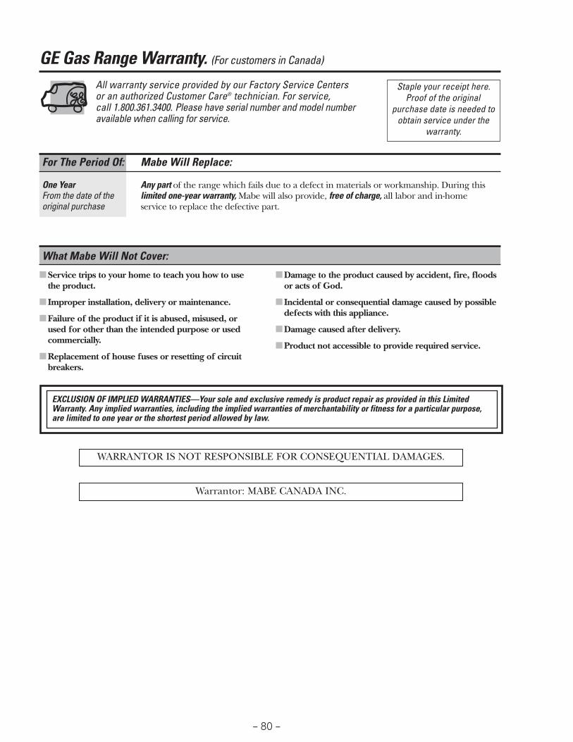
– 80 –
All warranty service provided by our Factory Service Centers or an authorized Customer Care® technician. For service, call 1.800.361.3400. Please have serial number and model number available when calling for service.
■ Service trips to your home to teach you how to use the product.
■ Improper installation, delivery or maintenance.
■ Failure of the product if it is abused, misused, or used for other than the intended purpose or usedcommercially.
■ Replacement of house fuses or resetting of circuitbreakers.
■ Damage to the product caused by accident, fire, floods or acts of God.
■ Incidental or consequential damage caused by possibledefects with this appliance.
■ Damage caused after delivery.
■ Product not accessible to provide required service.
What Mabe Will Not Cover:
For The Period Of: Mabe Will Replace:
One Year Any part of the range which fails due to a defect in materials or workmanship. During thisFrom the date of the limited one-year warranty, Mabe will also provide, free of charge, all labor and in-home original purchase service to replace the defective part.
WARRANTOR IS NOT RESPONSIBLE FOR CONSEQUENTIAL DAMAGES.
Warrantor: MABE CANADA INC.
GE Gas Range Warranty. (For customers in Canada)
Staple your receipt here. Proof of the original
purchase date is needed toobtain service under the
warranty.
EXCLUSION OF IMPLIED WARRANTIES—Your sole and exclusive remedy is product repair as provided in this LimitedWarranty. Any implied warranties, including the implied warranties of merchantability or fitness for a particular purpose,are limited to one year or the shortest period allowed by law.