gdl reference guide - graphisoft.com · introduction gdl reference guide iii introduction this...
TRANSCRIPT
GDL Reference Guide
GRAPHISOFT®
Visit the GRAPHISOFT website at http://www.graphisoft.com for local distributor and product availability information.GDL Reference GuideCopyright© 2012 by GRAPHISOFT, all rights reserved. Reproduction, paraphrasing or translation without express prior written permissionis strictly prohibited.TrademarksArchiCAD® is a registered trademark and PlotMaker, Virtual Building and GDL are trademarks of GRAPHISOFT. All other trademarks arethe property of their respective holders.
Introduction
GDL Reference Guide iii
IntroductionThis manual is a complete reference to the GRAPHISOFT's proprietary scripting language, GDL (Geometric Description Language). The manual is recommendedfor those users who wish to expand on the possibilities presented by the construction tools and object libraries in GRAPHISOFT software. It gives a detailed descriptionof GDL, including syntax definitions, commands, variables, etc.
GDL Reference Guide
GDL Reference Guide iv
Table of ContentsGeneral Overview . . . . . . . . . . . . . . . . . . . . . . . . . . . . . . . . . . . . . . . . . . . . . . . . . . . . . . . . . . . . . . . . . . . . . . . . . . . . . . . . . . . . . . . . . . . . . . . . . . . . . . . . . . . . . . . . . . . . . . . . . . . . . . . . . . . . . . . . . . . . . . . . . . . . . . . . . . . 1
Starting Out . . . . . . . . . . . . . . . . . . . . . . . . . . . . . . . . . . . . . . . . . . . . . . . . . . . . . . . . . . . . . . . . . . . . . . . . . . . . . . . . . . . . . . . . . . . . . . . . . . . . . . . . . . . . . . . . . . . . . . . . . . . . . . . . . . . . . . . . . . . . . . . . . . . . . . . . . . 1Scripting . . . . . . . . . . . . . . . . . . . . . . . . . . . . . . . . . . . . . . . . . . . . . . . . . . . . . . . . . . . . . . . . . . . . . . . . . . . . . . . . . . . . . . . . . . . . . . . . . . . . . . . . . . . . . . . . . . . . . . . . . . . . . . . . . . . . . . . . . . . . . . . . . . . . . . . . . . . . . . . 13D Generation . . . . . . . . . . . . . . . . . . . . . . . . . . . . . . . . . . . . . . . . . . . . . . . . . . . . . . . . . . . . . . . . . . . . . . . . . . . . . . . . . . . . . . . . . . . . . . . . . . . . . . . . . . . . . . . . . . . . . . . . . . . . . . . . . . . . . . . . . . . . . . . . . . . . . . . 7
GDL Syntax . . . . . . . . . . . . . . . . . . . . . . . . . . . . . . . . . . . . . . . . . . . . . . . . . . . . . . . . . . . . . . . . . . . . . . . . . . . . . . . . . . . . . . . . . . . . . . . . . . . . . . . . . . . . . . . . . . . . . . . . . . . . . . . . . . . . . . . . . . . . . . . . . . . . . . . . . . . . . . . . 10Rules of GDL Syntax . . . . . . . . . . . . . . . . . . . . . . . . . . . . . . . . . . . . . . . . . . . . . . . . . . . . . . . . . . . . . . . . . . . . . . . . . . . . . . . . . . . . . . . . . . . . . . . . . . . . . . . . . . . . . . . . . . . . . . . . . . . . . . . . . . . . . . . . . . . . 10Statements . . . . . . . . . . . . . . . . . . . . . . . . . . . . . . . . . . . . . . . . . . . . . . . . . . . . . . . . . . . . . . . . . . . . . . . . . . . . . . . . . . . . . . . . . . . . . . . . . . . . . . . . . . . . . . . . . . . . . . . . . . . . . . . . . . . . . . . . . . . . . . . . . . . . . . . . . . . 10Line . . . . . . . . . . . . . . . . . . . . . . . . . . . . . . . . . . . . . . . . . . . . . . . . . . . . . . . . . . . . . . . . . . . . . . . . . . . . . . . . . . . . . . . . . . . . . . . . . . . . . . . . . . . . . . . . . . . . . . . . . . . . . . . . . . . . . . . . . . . . . . . . . . . . . . . . . . . . . . . . . . . 10Label . . . . . . . . . . . . . . . . . . . . . . . . . . . . . . . . . . . . . . . . . . . . . . . . . . . . . . . . . . . . . . . . . . . . . . . . . . . . . . . . . . . . . . . . . . . . . . . . . . . . . . . . . . . . . . . . . . . . . . . . . . . . . . . . . . . . . . . . . . . . . . . . . . . . . . . . . . . . . . . . . . 10Characters . . . . . . . . . . . . . . . . . . . . . . . . . . . . . . . . . . . . . . . . . . . . . . . . . . . . . . . . . . . . . . . . . . . . . . . . . . . . . . . . . . . . . . . . . . . . . . . . . . . . . . . . . . . . . . . . . . . . . . . . . . . . . . . . . . . . . . . . . . . . . . . . . . . . . . . . . . . 10Strings . . . . . . . . . . . . . . . . . . . . . . . . . . . . . . . . . . . . . . . . . . . . . . . . . . . . . . . . . . . . . . . . . . . . . . . . . . . . . . . . . . . . . . . . . . . . . . . . . . . . . . . . . . . . . . . . . . . . . . . . . . . . . . . . . . . . . . . . . . . . . . . . . . . . . . . . . . . . . . . . 11Identifiers . . . . . . . . . . . . . . . . . . . . . . . . . . . . . . . . . . . . . . . . . . . . . . . . . . . . . . . . . . . . . . . . . . . . . . . . . . . . . . . . . . . . . . . . . . . . . . . . . . . . . . . . . . . . . . . . . . . . . . . . . . . . . . . . . . . . . . . . . . . . . . . . . . . . . . . . . . . . 11Variables . . . . . . . . . . . . . . . . . . . . . . . . . . . . . . . . . . . . . . . . . . . . . . . . . . . . . . . . . . . . . . . . . . . . . . . . . . . . . . . . . . . . . . . . . . . . . . . . . . . . . . . . . . . . . . . . . . . . . . . . . . . . . . . . . . . . . . . . . . . . . . . . . . . . . . . . . . . . . 11Parameters . . . . . . . . . . . . . . . . . . . . . . . . . . . . . . . . . . . . . . . . . . . . . . . . . . . . . . . . . . . . . . . . . . . . . . . . . . . . . . . . . . . . . . . . . . . . . . . . . . . . . . . . . . . . . . . . . . . . . . . . . . . . . . . . . . . . . . . . . . . . . . . . . . . . . . . . . . . 12Simple Types . . . . . . . . . . . . . . . . . . . . . . . . . . . . . . . . . . . . . . . . . . . . . . . . . . . . . . . . . . . . . . . . . . . . . . . . . . . . . . . . . . . . . . . . . . . . . . . . . . . . . . . . . . . . . . . . . . . . . . . . . . . . . . . . . . . . . . . . . . . . . . . . . . . . . . . . 12Derived Types . . . . . . . . . . . . . . . . . . . . . . . . . . . . . . . . . . . . . . . . . . . . . . . . . . . . . . . . . . . . . . . . . . . . . . . . . . . . . . . . . . . . . . . . . . . . . . . . . . . . . . . . . . . . . . . . . . . . . . . . . . . . . . . . . . . . . . . . . . . . . . . . . . . . . . 12Conventions used in this book . . . . . . . . . . . . . . . . . . . . . . . . . . . . . . . . . . . . . . . . . . . . . . . . . . . . . . . . . . . . . . . . . . . . . . . . . . . . . . . . . . . . . . . . . . . . . . . . . . . . . . . . . . . . . . . . . . . . . . . . . . . . . . . . 13
Coordinate Transformations . . . . . . . . . . . . . . . . . . . . . . . . . . . . . . . . . . . . . . . . . . . . . . . . . . . . . . . . . . . . . . . . . . . . . . . . . . . . . . . . . . . . . . . . . . . . . . . . . . . . . . . . . . . . . . . . . . . . . . . . . . . . . . . . . . . . . . . . . . . . 142D Transformations . . . . . . . . . . . . . . . . . . . . . . . . . . . . . . . . . . . . . . . . . . . . . . . . . . . . . . . . . . . . . . . . . . . . . . . . . . . . . . . . . . . . . . . . . . . . . . . . . . . . . . . . . . . . . . . . . . . . . . . . . . . . . . . . . . . . . . . . . . . . . . 14
ADD2 . . . . . . . . . . . . . . . . . . . . . . . . . . . . . . . . . . . . . . . . . . . . . . . . . . . . . . . . . . . . . . . . . . . . . . . . . . . . . . . . . . . . . . . . . . . . . . . . . . . . . . . . . . . . . . . . . . . . . . . . . . . . . . . . . . . . . . . . . . . . . . . . . . . . . . . . 14MUL2 . . . . . . . . . . . . . . . . . . . . . . . . . . . . . . . . . . . . . . . . . . . . . . . . . . . . . . . . . . . . . . . . . . . . . . . . . . . . . . . . . . . . . . . . . . . . . . . . . . . . . . . . . . . . . . . . . . . . . . . . . . . . . . . . . . . . . . . . . . . . . . . . . . . . . . . . . 14ROT2 . . . . . . . . . . . . . . . . . . . . . . . . . . . . . . . . . . . . . . . . . . . . . . . . . . . . . . . . . . . . . . . . . . . . . . . . . . . . . . . . . . . . . . . . . . . . . . . . . . . . . . . . . . . . . . . . . . . . . . . . . . . . . . . . . . . . . . . . . . . . . . . . . . . . . . . . . 15
3D Transformations . . . . . . . . . . . . . . . . . . . . . . . . . . . . . . . . . . . . . . . . . . . . . . . . . . . . . . . . . . . . . . . . . . . . . . . . . . . . . . . . . . . . . . . . . . . . . . . . . . . . . . . . . . . . . . . . . . . . . . . . . . . . . . . . . . . . . . . . . . . . . . 15ADDX .. . . . . . . . . . . . . . . . . . . . . . . . . . . . . . . . . . . . . . . . . . . . . . . . . . . . . . . . . . . . . . . . . . . . . . . . . . . . . . . . . . . . . . . . . . . . . . . . . . . . . . . . . . . . . . . . . . . . . . . . . . . . . . . . . . . . . . . . . . . . . . . . . . . . . . 15ADDY .. . . . . . . . . . . . . . . . . . . . . . . . . . . . . . . . . . . . . . . . . . . . . . . . . . . . . . . . . . . . . . . . . . . . . . . . . . . . . . . . . . . . . . . . . . . . . . . . . . . . . . . . . . . . . . . . . . . . . . . . . . . . . . . . . . . . . . . . . . . . . . . . . . . . . . . 15ADDZ .. . . . . . . . . . . . . . . . . . . . . . . . . . . . . . . . . . . . . . . . . . . . . . . . . . . . . . . . . . . . . . . . . . . . . . . . . . . . . . . . . . . . . . . . . . . . . . . . . . . . . . . . . . . . . . . . . . . . . . . . . . . . . . . . . . . . . . . . . . . . . . . . . . . . . . . 15ADD .. . . . . . . . . . . . . . . . . . . . . . . . . . . . . . . . . . . . . . . . . . . . . . . . . . . . . . . . . . . . . . . . . . . . . . . . . . . . . . . . . . . . . . . . . . . . . . . . . . . . . . . . . . . . . . . . . . . . . . . . . . . . . . . . . . . . . . . . . . . . . . . . . . . . . . . . . 15MULX .. . . . . . . . . . . . . . . . . . . . . . . . . . . . . . . . . . . . . . . . . . . . . . . . . . . . . . . . . . . . . . . . . . . . . . . . . . . . . . . . . . . . . . . . . . . . . . . . . . . . . . . . . . . . . . . . . . . . . . . . . . . . . . . . . . . . . . . . . . . . . . . . . . . . . . . 16MULY .. . . . . . . . . . . . . . . . . . . . . . . . . . . . . . . . . . . . . . . . . . . . . . . . . . . . . . . . . . . . . . . . . . . . . . . . . . . . . . . . . . . . . . . . . . . . . . . . . . . . . . . . . . . . . . . . . . . . . . . . . . . . . . . . . . . . . . . . . . . . . . . . . . . . . . . 16MULZ .. . . . . . . . . . . . . . . . . . . . . . . . . . . . . . . . . . . . . . . . . . . . . . . . . . . . . . . . . . . . . . . . . . . . . . . . . . . . . . . . . . . . . . . . . . . . . . . . . . . . . . . . . . . . . . . . . . . . . . . . . . . . . . . . . . . . . . . . . . . . . . . . . . . . . . . 16
GDL Reference Guide
GDL Reference Guide v
MUL . . . . . . . . . . . . . . . . . . . . . . . . . . . . . . . . . . . . . . . . . . . . . . . . . . . . . . . . . . . . . . . . . . . . . . . . . . . . . . . . . . . . . . . . . . . . . . . . . . . . . . . . . . . . . . . . . . . . . . . . . . . . . . . . . . . . . . . . . . . . . . . . . . . . . . . . . . 16ROTX .. . . . . . . . . . . . . . . . . . . . . . . . . . . . . . . . . . . . . . . . . . . . . . . . . . . . . . . . . . . . . . . . . . . . . . . . . . . . . . . . . . . . . . . . . . . . . . . . . . . . . . . . . . . . . . . . . . . . . . . . . . . . . . . . . . . . . . . . . . . . . . . . . . . . . . . 16ROTY .. . . . . . . . . . . . . . . . . . . . . . . . . . . . . . . . . . . . . . . . . . . . . . . . . . . . . . . . . . . . . . . . . . . . . . . . . . . . . . . . . . . . . . . . . . . . . . . . . . . . . . . . . . . . . . . . . . . . . . . . . . . . . . . . . . . . . . . . . . . . . . . . . . . . . . . 16ROTZ .. . . . . . . . . . . . . . . . . . . . . . . . . . . . . . . . . . . . . . . . . . . . . . . . . . . . . . . . . . . . . . . . . . . . . . . . . . . . . . . . . . . . . . . . . . . . . . . . . . . . . . . . . . . . . . . . . . . . . . . . . . . . . . . . . . . . . . . . . . . . . . . . . . . . . . . 17ROT .. . . . . . . . . . . . . . . . . . . . . . . . . . . . . . . . . . . . . . . . . . . . . . . . . . . . . . . . . . . . . . . . . . . . . . . . . . . . . . . . . . . . . . . . . . . . . . . . . . . . . . . . . . . . . . . . . . . . . . . . . . . . . . . . . . . . . . . . . . . . . . . . . . . . . . . . . 17XFORM .. . . . . . . . . . . . . . . . . . . . . . . . . . . . . . . . . . . . . . . . . . . . . . . . . . . . . . . . . . . . . . . . . . . . . . . . . . . . . . . . . . . . . . . . . . . . . . . . . . . . . . . . . . . . . . . . . . . . . . . . . . . . . . . . . . . . . . . . . . . . . . . . . . . . 17
Managing the Transformation Stack . . . . . . . . . . . . . . . . . . . . . . . . . . . . . . . . . . . . . . . . . . . . . . . . . . . . . . . . . . . . . . . . . . . . . . . . . . . . . . . . . . . . . . . . . . . . . . . . . . . . . . . . . . . . . . . . . . . . . . . . . . 18DEL . . . . . . . . . . . . . . . . . . . . . . . . . . . . . . . . . . . . . . . . . . . . . . . . . . . . . . . . . . . . . . . . . . . . . . . . . . . . . . . . . . . . . . . . . . . . . . . . . . . . . . . . . . . . . . . . . . . . . . . . . . . . . . . . . . . . . . . . . . . . . . . . . . . . . . . . . . 18DEL TOP . . . . . . . . . . . . . . . . . . . . . . . . . . . . . . . . . . . . . . . . . . . . . . . . . . . . . . . . . . . . . . . . . . . . . . . . . . . . . . . . . . . . . . . . . . . . . . . . . . . . . . . . . . . . . . . . . . . . . . . . . . . . . . . . . . . . . . . . . . . . . . . . . . . 18NTR . . . . . . . . . . . . . . . . . . . . . . . . . . . . . . . . . . . . . . . . . . . . . . . . . . . . . . . . . . . . . . . . . . . . . . . . . . . . . . . . . . . . . . . . . . . . . . . . . . . . . . . . . . . . . . . . . . . . . . . . . . . . . . . . . . . . . . . . . . . . . . . . . . . . . . . . . . 18
3D Shapes . . . . . . . . . . . . . . . . . . . . . . . . . . . . . . . . . . . . . . . . . . . . . . . . . . . . . . . . . . . . . . . . . . . . . . . . . . . . . . . . . . . . . . . . . . . . . . . . . . . . . . . . . . . . . . . . . . . . . . . . . . . . . . . . . . . . . . . . . . . . . . . . . . . . . . . . . . . . . . . . . . . 20Basic Shapes . . . . . . . . . . . . . . . . . . . . . . . . . . . . . . . . . . . . . . . . . . . . . . . . . . . . . . . . . . . . . . . . . . . . . . . . . . . . . . . . . . . . . . . . . . . . . . . . . . . . . . . . . . . . . . . . . . . . . . . . . . . . . . . . . . . . . . . . . . . . . . . . . . . . . . . . 20
BLOCK .. . . . . . . . . . . . . . . . . . . . . . . . . . . . . . . . . . . . . . . . . . . . . . . . . . . . . . . . . . . . . . . . . . . . . . . . . . . . . . . . . . . . . . . . . . . . . . . . . . . . . . . . . . . . . . . . . . . . . . . . . . . . . . . . . . . . . . . . . . . . . . . . . . . . . 20BRICK .. . . . . . . . . . . . . . . . . . . . . . . . . . . . . . . . . . . . . . . . . . . . . . . . . . . . . . . . . . . . . . . . . . . . . . . . . . . . . . . . . . . . . . . . . . . . . . . . . . . . . . . . . . . . . . . . . . . . . . . . . . . . . . . . . . . . . . . . . . . . . . . . . . . . . . 20CYLIND .. . . . . . . . . . . . . . . . . . . . . . . . . . . . . . . . . . . . . . . . . . . . . . . . . . . . . . . . . . . . . . . . . . . . . . . . . . . . . . . . . . . . . . . . . . . . . . . . . . . . . . . . . . . . . . . . . . . . . . . . . . . . . . . . . . . . . . . . . . . . . . . . . . . . 21SPHERE .. . . . . . . . . . . . . . . . . . . . . . . . . . . . . . . . . . . . . . . . . . . . . . . . . . . . . . . . . . . . . . . . . . . . . . . . . . . . . . . . . . . . . . . . . . . . . . . . . . . . . . . . . . . . . . . . . . . . . . . . . . . . . . . . . . . . . . . . . . . . . . . . . . . . 21ELLIPS . . . . . . . . . . . . . . . . . . . . . . . . . . . . . . . . . . . . . . . . . . . . . . . . . . . . . . . . . . . . . . . . . . . . . . . . . . . . . . . . . . . . . . . . . . . . . . . . . . . . . . . . . . . . . . . . . . . . . . . . . . . . . . . . . . . . . . . . . . . . . . . . . . . . . . 22CONE .. . . . . . . . . . . . . . . . . . . . . . . . . . . . . . . . . . . . . . . . . . . . . . . . . . . . . . . . . . . . . . . . . . . . . . . . . . . . . . . . . . . . . . . . . . . . . . . . . . . . . . . . . . . . . . . . . . . . . . . . . . . . . . . . . . . . . . . . . . . . . . . . . . . . . . . 23PRISM .. . . . . . . . . . . . . . . . . . . . . . . . . . . . . . . . . . . . . . . . . . . . . . . . . . . . . . . . . . . . . . . . . . . . . . . . . . . . . . . . . . . . . . . . . . . . . . . . . . . . . . . . . . . . . . . . . . . . . . . . . . . . . . . . . . . . . . . . . . . . . . . . . . . . . . . 23PRISM_ . . . . . . . . . . . . . . . . . . . . . . . . . . . . . . . . . . . . . . . . . . . . . . . . . . . . . . . . . . . . . . . . . . . . . . . . . . . . . . . . . . . . . . . . . . . . . . . . . . . . . . . . . . . . . . . . . . . . . . . . . . . . . . . . . . . . . . . . . . . . . . . . . . . . . . 24CPRISM_ . . . . . . . . . . . . . . . . . . . . . . . . . . . . . . . . . . . . . . . . . . . . . . . . . . . . . . . . . . . . . . . . . . . . . . . . . . . . . . . . . . . . . . . . . . . . . . . . . . . . . . . . . . . . . . . . . . . . . . . . . . . . . . . . . . . . . . . . . . . . . . . . . . . . 27CPRISM_{2} . . . . . . . . . . . . . . . . . . . . . . . . . . . . . . . . . . . . . . . . . . . . . . . . . . . . . . . . . . . . . . . . . . . . . . . . . . . . . . . . . . . . . . . . . . . . . . . . . . . . . . . . . . . . . . . . . . . . . . . . . . . . . . . . . . . . . . . . . . . . . . . 28BPRISM_ . . . . . . . . . . . . . . . . . . . . . . . . . . . . . . . . . . . . . . . . . . . . . . . . . . . . . . . . . . . . . . . . . . . . . . . . . . . . . . . . . . . . . . . . . . . . . . . . . . . . . . . . . . . . . . . . . . . . . . . . . . . . . . . . . . . . . . . . . . . . . . . . . . . . 29FPRISM_ . . . . . . . . . . . . . . . . . . . . . . . . . . . . . . . . . . . . . . . . . . . . . . . . . . . . . . . . . . . . . . . . . . . . . . . . . . . . . . . . . . . . . . . . . . . . . . . . . . . . . . . . . . . . . . . . . . . . . . . . . . . . . . . . . . . . . . . . . . . . . . . . . . . . 30HPRISM_ . . . . . . . . . . . . . . . . . . . . . . . . . . . . . . . . . . . . . . . . . . . . . . . . . . . . . . . . . . . . . . . . . . . . . . . . . . . . . . . . . . . . . . . . . . . . . . . . . . . . . . . . . . . . . . . . . . . . . . . . . . . . . . . . . . . . . . . . . . . . . . . . . . . 32SPRISM_ . . . . . . . . . . . . . . . . . . . . . . . . . . . . . . . . . . . . . . . . . . . . . . . . . . . . . . . . . . . . . . . . . . . . . . . . . . . . . . . . . . . . . . . . . . . . . . . . . . . . . . . . . . . . . . . . . . . . . . . . . . . . . . . . . . . . . . . . . . . . . . . . . . . . 33SPRISM_{2} . . . . . . . . . . . . . . . . . . . . . . . . . . . . . . . . . . . . . . . . . . . . . . . . . . . . . . . . . . . . . . . . . . . . . . . . . . . . . . . . . . . . . . . . . . . . . . . . . . . . . . . . . . . . . . . . . . . . . . . . . . . . . . . . . . . . . . . . . . . . . . . . 34SLAB . . . . . . . . . . . . . . . . . . . . . . . . . . . . . . . . . . . . . . . . . . . . . . . . . . . . . . . . . . . . . . . . . . . . . . . . . . . . . . . . . . . . . . . . . . . . . . . . . . . . . . . . . . . . . . . . . . . . . . . . . . . . . . . . . . . . . . . . . . . . . . . . . . . . . . . . . 35SLAB_ . . . . . . . . . . . . . . . . . . . . . . . . . . . . . . . . . . . . . . . . . . . . . . . . . . . . . . . . . . . . . . . . . . . . . . . . . . . . . . . . . . . . . . . . . . . . . . . . . . . . . . . . . . . . . . . . . . . . . . . . . . . . . . . . . . . . . . . . . . . . . . . . . . . . . . . . 36CSLAB_ . . . . . . . . . . . . . . . . . . . . . . . . . . . . . . . . . . . . . . . . . . . . . . . . . . . . . . . . . . . . . . . . . . . . . . . . . . . . . . . . . . . . . . . . . . . . . . . . . . . . . . . . . . . . . . . . . . . . . . . . . . . . . . . . . . . . . . . . . . . . . . . . . . . . . . 36CWALL_ . . . . . . . . . . . . . . . . . . . . . . . . . . . . . . . . . . . . . . . . . . . . . . . . . . . . . . . . . . . . . . . . . . . . . . . . . . . . . . . . . . . . . . . . . . . . . . . . . . . . . . . . . . . . . . . . . . . . . . . . . . . . . . . . . . . . . . . . . . . . . . . . . . . . . 37BWALL_ . . . . . . . . . . . . . . . . . . . . . . . . . . . . . . . . . . . . . . . . . . . . . . . . . . . . . . . . . . . . . . . . . . . . . . . . . . . . . . . . . . . . . . . . . . . . . . . . . . . . . . . . . . . . . . . . . . . . . . . . . . . . . . . . . . . . . . . . . . . . . . . . . . . . . 40XWALL_ . . . . . . . . . . . . . . . . . . . . . . . . . . . . . . . . . . . . . . . . . . . . . . . . . . . . . . . . . . . . . . . . . . . . . . . . . . . . . . . . . . . . . . . . . . . . . . . . . . . . . . . . . . . . . . . . . . . . . . . . . . . . . . . . . . . . . . . . . . . . . . . . . . . . 42
GDL Reference Guide
GDL Reference Guide vi
XWALL_{2} . . . . . . . . . . . . . . . . . . . . . . . . . . . . . . . . . . . . . . . . . . . . . . . . . . . . . . . . . . . . . . . . . . . . . . . . . . . . . . . . . . . . . . . . . . . . . . . . . . . . . . . . . . . . . . . . . . . . . . . . . . . . . . . . . . . . . . . . . . . . . . . . 45BEAM .. . . . . . . . . . . . . . . . . . . . . . . . . . . . . . . . . . . . . . . . . . . . . . . . . . . . . . . . . . . . . . . . . . . . . . . . . . . . . . . . . . . . . . . . . . . . . . . . . . . . . . . . . . . . . . . . . . . . . . . . . . . . . . . . . . . . . . . . . . . . . . . . . . . . . . . 48CROOF_ . . . . . . . . . . . . . . . . . . . . . . . . . . . . . . . . . . . . . . . . . . . . . . . . . . . . . . . . . . . . . . . . . . . . . . . . . . . . . . . . . . . . . . . . . . . . . . . . . . . . . . . . . . . . . . . . . . . . . . . . . . . . . . . . . . . . . . . . . . . . . . . . . . . . 48CROOF_{2} . . . . . . . . . . . . . . . . . . . . . . . . . . . . . . . . . . . . . . . . . . . . . . . . . . . . . . . . . . . . . . . . . . . . . . . . . . . . . . . . . . . . . . . . . . . . . . . . . . . . . . . . . . . . . . . . . . . . . . . . . . . . . . . . . . . . . . . . . . . . . . . 51MESH .. . . . . . . . . . . . . . . . . . . . . . . . . . . . . . . . . . . . . . . . . . . . . . . . . . . . . . . . . . . . . . . . . . . . . . . . . . . . . . . . . . . . . . . . . . . . . . . . . . . . . . . . . . . . . . . . . . . . . . . . . . . . . . . . . . . . . . . . . . . . . . . . . . . . . . . 52ARMC .. . . . . . . . . . . . . . . . . . . . . . . . . . . . . . . . . . . . . . . . . . . . . . . . . . . . . . . . . . . . . . . . . . . . . . . . . . . . . . . . . . . . . . . . . . . . . . . . . . . . . . . . . . . . . . . . . . . . . . . . . . . . . . . . . . . . . . . . . . . . . . . . . . . . . . . 54ARME .. . . . . . . . . . . . . . . . . . . . . . . . . . . . . . . . . . . . . . . . . . . . . . . . . . . . . . . . . . . . . . . . . . . . . . . . . . . . . . . . . . . . . . . . . . . . . . . . . . . . . . . . . . . . . . . . . . . . . . . . . . . . . . . . . . . . . . . . . . . . . . . . . . . . . . . 55ELBOW .. . . . . . . . . . . . . . . . . . . . . . . . . . . . . . . . . . . . . . . . . . . . . . . . . . . . . . . . . . . . . . . . . . . . . . . . . . . . . . . . . . . . . . . . . . . . . . . . . . . . . . . . . . . . . . . . . . . . . . . . . . . . . . . . . . . . . . . . . . . . . . . . . . . . . 55
Planar Shapes in 3D . . . . . . . . . . . . . . . . . . . . . . . . . . . . . . . . . . . . . . . . . . . . . . . . . . . . . . . . . . . . . . . . . . . . . . . . . . . . . . . . . . . . . . . . . . . . . . . . . . . . . . . . . . . . . . . . . . . . . . . . . . . . . . . . . . . . . . . . . . . . . . 56HOTSPOT .. . . . . . . . . . . . . . . . . . . . . . . . . . . . . . . . . . . . . . . . . . . . . . . . . . . . . . . . . . . . . . . . . . . . . . . . . . . . . . . . . . . . . . . . . . . . . . . . . . . . . . . . . . . . . . . . . . . . . . . . . . . . . . . . . . . . . . . . . . . . . . . . . 57HOTLINE .. . . . . . . . . . . . . . . . . . . . . . . . . . . . . . . . . . . . . . . . . . . . . . . . . . . . . . . . . . . . . . . . . . . . . . . . . . . . . . . . . . . . . . . . . . . . . . . . . . . . . . . . . . . . . . . . . . . . . . . . . . . . . . . . . . . . . . . . . . . . . . . . . 57HOTARC .. . . . . . . . . . . . . . . . . . . . . . . . . . . . . . . . . . . . . . . . . . . . . . . . . . . . . . . . . . . . . . . . . . . . . . . . . . . . . . . . . . . . . . . . . . . . . . . . . . . . . . . . . . . . . . . . . . . . . . . . . . . . . . . . . . . . . . . . . . . . . . . . . . . 57LIN_ . . . . . . . . . . . . . . . . . . . . . . . . . . . . . . . . . . . . . . . . . . . . . . . . . . . . . . . . . . . . . . . . . . . . . . . . . . . . . . . . . . . . . . . . . . . . . . . . . . . . . . . . . . . . . . . . . . . . . . . . . . . . . . . . . . . . . . . . . . . . . . . . . . . . . . . . . . 57RECT . . . . . . . . . . . . . . . . . . . . . . . . . . . . . . . . . . . . . . . . . . . . . . . . . . . . . . . . . . . . . . . . . . . . . . . . . . . . . . . . . . . . . . . . . . . . . . . . . . . . . . . . . . . . . . . . . . . . . . . . . . . . . . . . . . . . . . . . . . . . . . . . . . . . . . . . . 57POLY .. . . . . . . . . . . . . . . . . . . . . . . . . . . . . . . . . . . . . . . . . . . . . . . . . . . . . . . . . . . . . . . . . . . . . . . . . . . . . . . . . . . . . . . . . . . . . . . . . . . . . . . . . . . . . . . . . . . . . . . . . . . . . . . . . . . . . . . . . . . . . . . . . . . . . . . . 58POLY_ . . . . . . . . . . . . . . . . . . . . . . . . . . . . . . . . . . . . . . . . . . . . . . . . . . . . . . . . . . . . . . . . . . . . . . . . . . . . . . . . . . . . . . . . . . . . . . . . . . . . . . . . . . . . . . . . . . . . . . . . . . . . . . . . . . . . . . . . . . . . . . . . . . . . . . . 58PLANE .. . . . . . . . . . . . . . . . . . . . . . . . . . . . . . . . . . . . . . . . . . . . . . . . . . . . . . . . . . . . . . . . . . . . . . . . . . . . . . . . . . . . . . . . . . . . . . . . . . . . . . . . . . . . . . . . . . . . . . . . . . . . . . . . . . . . . . . . . . . . . . . . . . . . . 59PLANE_ . . . . . . . . . . . . . . . . . . . . . . . . . . . . . . . . . . . . . . . . . . . . . . . . . . . . . . . . . . . . . . . . . . . . . . . . . . . . . . . . . . . . . . . . . . . . . . . . . . . . . . . . . . . . . . . . . . . . . . . . . . . . . . . . . . . . . . . . . . . . . . . . . . . . . 59CIRCLE . . . . . . . . . . . . . . . . . . . . . . . . . . . . . . . . . . . . . . . . . . . . . . . . . . . . . . . . . . . . . . . . . . . . . . . . . . . . . . . . . . . . . . . . . . . . . . . . . . . . . . . . . . . . . . . . . . . . . . . . . . . . . . . . . . . . . . . . . . . . . . . . . . . . . . 59ARC . . . . . . . . . . . . . . . . . . . . . . . . . . . . . . . . . . . . . . . . . . . . . . . . . . . . . . . . . . . . . . . . . . . . . . . . . . . . . . . . . . . . . . . . . . . . . . . . . . . . . . . . . . . . . . . . . . . . . . . . . . . . . . . . . . . . . . . . . . . . . . . . . . . . . . . . . . . 60
Shapes Generated from Polylines . . . . . . . . . . . . . . . . . . . . . . . . . . . . . . . . . . . . . . . . . . . . . . . . . . . . . . . . . . . . . . . . . . . . . . . . . . . . . . . . . . . . . . . . . . . . . . . . . . . . . . . . . . . . . . . . . . . . . . . . . . . . . 60EXTRUDE .. . . . . . . . . . . . . . . . . . . . . . . . . . . . . . . . . . . . . . . . . . . . . . . . . . . . . . . . . . . . . . . . . . . . . . . . . . . . . . . . . . . . . . . . . . . . . . . . . . . . . . . . . . . . . . . . . . . . . . . . . . . . . . . . . . . . . . . . . . . . . . . . 62PYRAMID .. . . . . . . . . . . . . . . . . . . . . . . . . . . . . . . . . . . . . . . . . . . . . . . . . . . . . . . . . . . . . . . . . . . . . . . . . . . . . . . . . . . . . . . . . . . . . . . . . . . . . . . . . . . . . . . . . . . . . . . . . . . . . . . . . . . . . . . . . . . . . . . . . 65REVOLVE .. . . . . . . . . . . . . . . . . . . . . . . . . . . . . . . . . . . . . . . . . . . . . . . . . . . . . . . . . . . . . . . . . . . . . . . . . . . . . . . . . . . . . . . . . . . . . . . . . . . . . . . . . . . . . . . . . . . . . . . . . . . . . . . . . . . . . . . . . . . . . . . . . 67REVOLVE{2} . . . . . . . . . . . . . . . . . . . . . . . . . . . . . . . . . . . . . . . . . . . . . . . . . . . . . . . . . . . . . . . . . . . . . . . . . . . . . . . . . . . . . . . . . . . . . . . . . . . . . . . . . . . . . . . . . . . . . . . . . . . . . . . . . . . . . . . . . . . . . 69RULED .. . . . . . . . . . . . . . . . . . . . . . . . . . . . . . . . . . . . . . . . . . . . . . . . . . . . . . . . . . . . . . . . . . . . . . . . . . . . . . . . . . . . . . . . . . . . . . . . . . . . . . . . . . . . . . . . . . . . . . . . . . . . . . . . . . . . . . . . . . . . . . . . . . . . . 73RULED{2} . . . . . . . . . . . . . . . . . . . . . . . . . . . . . . . . . . . . . . . . . . . . . . . . . . . . . . . . . . . . . . . . . . . . . . . . . . . . . . . . . . . . . . . . . . . . . . . . . . . . . . . . . . . . . . . . . . . . . . . . . . . . . . . . . . . . . . . . . . . . . . . . . 74SWEEP . . . . . . . . . . . . . . . . . . . . . . . . . . . . . . . . . . . . . . . . . . . . . . . . . . . . . . . . . . . . . . . . . . . . . . . . . . . . . . . . . . . . . . . . . . . . . . . . . . . . . . . . . . . . . . . . . . . . . . . . . . . . . . . . . . . . . . . . . . . . . . . . . . . . . . 77TUBE .. . . . . . . . . . . . . . . . . . . . . . . . . . . . . . . . . . . . . . . . . . . . . . . . . . . . . . . . . . . . . . . . . . . . . . . . . . . . . . . . . . . . . . . . . . . . . . . . . . . . . . . . . . . . . . . . . . . . . . . . . . . . . . . . . . . . . . . . . . . . . . . . . . . . . . . 79TUBEA .. . . . . . . . . . . . . . . . . . . . . . . . . . . . . . . . . . . . . . . . . . . . . . . . . . . . . . . . . . . . . . . . . . . . . . . . . . . . . . . . . . . . . . . . . . . . . . . . . . . . . . . . . . . . . . . . . . . . . . . . . . . . . . . . . . . . . . . . . . . . . . . . . . . . . 84COONS . . . . . . . . . . . . . . . . . . . . . . . . . . . . . . . . . . . . . . . . . . . . . . . . . . . . . . . . . . . . . . . . . . . . . . . . . . . . . . . . . . . . . . . . . . . . . . . . . . . . . . . . . . . . . . . . . . . . . . . . . . . . . . . . . . . . . . . . . . . . . . . . . . . . . . 86MASS . . . . . . . . . . . . . . . . . . . . . . . . . . . . . . . . . . . . . . . . . . . . . . . . . . . . . . . . . . . . . . . . . . . . . . . . . . . . . . . . . . . . . . . . . . . . . . . . . . . . . . . . . . . . . . . . . . . . . . . . . . . . . . . . . . . . . . . . . . . . . . . . . . . . . . . . . 90POLYROOF .. . . . . . . . . . . . . . . . . . . . . . . . . . . . . . . . . . . . . . . . . . . . . . . . . . . . . . . . . . . . . . . . . . . . . . . . . . . . . . . . . . . . . . . . . . . . . . . . . . . . . . . . . . . . . . . . . . . . . . . . . . . . . . . . . . . . . . . . . . . . . . . 93
GDL Reference Guide
GDL Reference Guide vii
EXTRUDEDSHELL . . . . . . . . . . . . . . . . . . . . . . . . . . . . . . . . . . . . . . . . . . . . . . . . . . . . . . . . . . . . . . . . . . . . . . . . . . . . . . . . . . . . . . . . . . . . . . . . . . . . . . . . . . . . . . . . . . . . . . . . . . . . . . . . . . . . . 97REVOLVEDSHELL . . . . . . . . . . . . . . . . . . . . . . . . . . . . . . . . . . . . . . . . . . . . . . . . . . . . . . . . . . . . . . . . . . . . . . . . . . . . . . . . . . . . . . . . . . . . . . . . . . . . . . . . . . . . . . . . . . . . . . . . . . . . . . . . . . . . . 99REVOLVEDSHELLANGULAR .. . . . . . . . . . . . . . . . . . . . . . . . . . . . . . . . . . . . . . . . . . . . . . . . . . . . . . . . . . . . . . . . . . . . . . . . . . . . . . . . . . . . . . . . . . . . . . . . . . . . . . . . . . . . . . . . . . . 101RULEDSHELL . . . . . . . . . . . . . . . . . . . . . . . . . . . . . . . . . . . . . . . . . . . . . . . . . . . . . . . . . . . . . . . . . . . . . . . . . . . . . . . . . . . . . . . . . . . . . . . . . . . . . . . . . . . . . . . . . . . . . . . . . . . . . . . . . . . . . . . . . . 102
Elements for Visualization . . . . . . . . . . . . . . . . . . . . . . . . . . . . . . . . . . . . . . . . . . . . . . . . . . . . . . . . . . . . . . . . . . . . . . . . . . . . . . . . . . . . . . . . . . . . . . . . . . . . . . . . . . . . . . . . . . . . . . . . . . . . . . . . . . . . . 104LIGHT .. . . . . . . . . . . . . . . . . . . . . . . . . . . . . . . . . . . . . . . . . . . . . . . . . . . . . . . . . . . . . . . . . . . . . . . . . . . . . . . . . . . . . . . . . . . . . . . . . . . . . . . . . . . . . . . . . . . . . . . . . . . . . . . . . . . . . . . . . . . . . . . . . . . . 104PICTURE .. . . . . . . . . . . . . . . . . . . . . . . . . . . . . . . . . . . . . . . . . . . . . . . . . . . . . . . . . . . . . . . . . . . . . . . . . . . . . . . . . . . . . . . . . . . . . . . . . . . . . . . . . . . . . . . . . . . . . . . . . . . . . . . . . . . . . . . . . . . . . . . . . 108
3D Text Elements . . . . . . . . . . . . . . . . . . . . . . . . . . . . . . . . . . . . . . . . . . . . . . . . . . . . . . . . . . . . . . . . . . . . . . . . . . . . . . . . . . . . . . . . . . . . . . . . . . . . . . . . . . . . . . . . . . . . . . . . . . . . . . . . . . . . . . . . . . . . . . . 110TEXT .. . . . . . . . . . . . . . . . . . . . . . . . . . . . . . . . . . . . . . . . . . . . . . . . . . . . . . . . . . . . . . . . . . . . . . . . . . . . . . . . . . . . . . . . . . . . . . . . . . . . . . . . . . . . . . . . . . . . . . . . . . . . . . . . . . . . . . . . . . . . . . . . . . . . . . 110RICHTEXT .. . . . . . . . . . . . . . . . . . . . . . . . . . . . . . . . . . . . . . . . . . . . . . . . . . . . . . . . . . . . . . . . . . . . . . . . . . . . . . . . . . . . . . . . . . . . . . . . . . . . . . . . . . . . . . . . . . . . . . . . . . . . . . . . . . . . . . . . . . . . . . 111
Primitive Elements . . . . . . . . . . . . . . . . . . . . . . . . . . . . . . . . . . . . . . . . . . . . . . . . . . . . . . . . . . . . . . . . . . . . . . . . . . . . . . . . . . . . . . . . . . . . . . . . . . . . . . . . . . . . . . . . . . . . . . . . . . . . . . . . . . . . . . . . . . . . . . . 111VERT . . . . . . . . . . . . . . . . . . . . . . . . . . . . . . . . . . . . . . . . . . . . . . . . . . . . . . . . . . . . . . . . . . . . . . . . . . . . . . . . . . . . . . . . . . . . . . . . . . . . . . . . . . . . . . . . . . . . . . . . . . . . . . . . . . . . . . . . . . . . . . . . . . . . . . . 112TEVE .. . . . . . . . . . . . . . . . . . . . . . . . . . . . . . . . . . . . . . . . . . . . . . . . . . . . . . . . . . . . . . . . . . . . . . . . . . . . . . . . . . . . . . . . . . . . . . . . . . . . . . . . . . . . . . . . . . . . . . . . . . . . . . . . . . . . . . . . . . . . . . . . . . . . . . 112VECT . . . . . . . . . . . . . . . . . . . . . . . . . . . . . . . . . . . . . . . . . . . . . . . . . . . . . . . . . . . . . . . . . . . . . . . . . . . . . . . . . . . . . . . . . . . . . . . . . . . . . . . . . . . . . . . . . . . . . . . . . . . . . . . . . . . . . . . . . . . . . . . . . . . . . . . 112EDGE .. . . . . . . . . . . . . . . . . . . . . . . . . . . . . . . . . . . . . . . . . . . . . . . . . . . . . . . . . . . . . . . . . . . . . . . . . . . . . . . . . . . . . . . . . . . . . . . . . . . . . . . . . . . . . . . . . . . . . . . . . . . . . . . . . . . . . . . . . . . . . . . . . . . . . 113PGON .. . . . . . . . . . . . . . . . . . . . . . . . . . . . . . . . . . . . . . . . . . . . . . . . . . . . . . . . . . . . . . . . . . . . . . . . . . . . . . . . . . . . . . . . . . . . . . . . . . . . . . . . . . . . . . . . . . . . . . . . . . . . . . . . . . . . . . . . . . . . . . . . . . . . . 113PGON{2} . . . . . . . . . . . . . . . . . . . . . . . . . . . . . . . . . . . . . . . . . . . . . . . . . . . . . . . . . . . . . . . . . . . . . . . . . . . . . . . . . . . . . . . . . . . . . . . . . . . . . . . . . . . . . . . . . . . . . . . . . . . . . . . . . . . . . . . . . . . . . . . . . 114PIPG .. . . . . . . . . . . . . . . . . . . . . . . . . . . . . . . . . . . . . . . . . . . . . . . . . . . . . . . . . . . . . . . . . . . . . . . . . . . . . . . . . . . . . . . . . . . . . . . . . . . . . . . . . . . . . . . . . . . . . . . . . . . . . . . . . . . . . . . . . . . . . . . . . . . . . . . 114COOR .. . . . . . . . . . . . . . . . . . . . . . . . . . . . . . . . . . . . . . . . . . . . . . . . . . . . . . . . . . . . . . . . . . . . . . . . . . . . . . . . . . . . . . . . . . . . . . . . . . . . . . . . . . . . . . . . . . . . . . . . . . . . . . . . . . . . . . . . . . . . . . . . . . . . . 114BODY .. . . . . . . . . . . . . . . . . . . . . . . . . . . . . . . . . . . . . . . . . . . . . . . . . . . . . . . . . . . . . . . . . . . . . . . . . . . . . . . . . . . . . . . . . . . . . . . . . . . . . . . . . . . . . . . . . . . . . . . . . . . . . . . . . . . . . . . . . . . . . . . . . . . . . 116BASE . . . . . . . . . . . . . . . . . . . . . . . . . . . . . . . . . . . . . . . . . . . . . . . . . . . . . . . . . . . . . . . . . . . . . . . . . . . . . . . . . . . . . . . . . . . . . . . . . . . . . . . . . . . . . . . . . . . . . . . . . . . . . . . . . . . . . . . . . . . . . . . . . . . . . . . . 119
Cutting in 3D . . . . . . . . . . . . . . . . . . . . . . . . . . . . . . . . . . . . . . . . . . . . . . . . . . . . . . . . . . . . . . . . . . . . . . . . . . . . . . . . . . . . . . . . . . . . . . . . . . . . . . . . . . . . . . . . . . . . . . . . . . . . . . . . . . . . . . . . . . . . . . . . . . . . . 120CUTPLANE .. . . . . . . . . . . . . . . . . . . . . . . . . . . . . . . . . . . . . . . . . . . . . . . . . . . . . . . . . . . . . . . . . . . . . . . . . . . . . . . . . . . . . . . . . . . . . . . . . . . . . . . . . . . . . . . . . . . . . . . . . . . . . . . . . . . . . . . . . . . . . 120CUTPLANE{2} . . . . . . . . . . . . . . . . . . . . . . . . . . . . . . . . . . . . . . . . . . . . . . . . . . . . . . . . . . . . . . . . . . . . . . . . . . . . . . . . . . . . . . . . . . . . . . . . . . . . . . . . . . . . . . . . . . . . . . . . . . . . . . . . . . . . . . . . . 120CUTPLANE{3} . . . . . . . . . . . . . . . . . . . . . . . . . . . . . . . . . . . . . . . . . . . . . . . . . . . . . . . . . . . . . . . . . . . . . . . . . . . . . . . . . . . . . . . . . . . . . . . . . . . . . . . . . . . . . . . . . . . . . . . . . . . . . . . . . . . . . . . . . 120CUTPOLY .. . . . . . . . . . . . . . . . . . . . . . . . . . . . . . . . . . . . . . . . . . . . . . . . . . . . . . . . . . . . . . . . . . . . . . . . . . . . . . . . . . . . . . . . . . . . . . . . . . . . . . . . . . . . . . . . . . . . . . . . . . . . . . . . . . . . . . . . . . . . . . . . 123CUTPOLYA .. . . . . . . . . . . . . . . . . . . . . . . . . . . . . . . . . . . . . . . . . . . . . . . . . . . . . . . . . . . . . . . . . . . . . . . . . . . . . . . . . . . . . . . . . . . . . . . . . . . . . . . . . . . . . . . . . . . . . . . . . . . . . . . . . . . . . . . . . . . . . . 126CUTSHAPE .. . . . . . . . . . . . . . . . . . . . . . . . . . . . . . . . . . . . . . . . . . . . . . . . . . . . . . . . . . . . . . . . . . . . . . . . . . . . . . . . . . . . . . . . . . . . . . . . . . . . . . . . . . . . . . . . . . . . . . . . . . . . . . . . . . . . . . . . . . . . . . 129CUTFORM .. . . . . . . . . . . . . . . . . . . . . . . . . . . . . . . . . . . . . . . . . . . . . . . . . . . . . . . . . . . . . . . . . . . . . . . . . . . . . . . . . . . . . . . . . . . . . . . . . . . . . . . . . . . . . . . . . . . . . . . . . . . . . . . . . . . . . . . . . . . . . . . 129
Solid Geometry Commands . . . . . . . . . . . . . . . . . . . . . . . . . . . . . . . . . . . . . . . . . . . . . . . . . . . . . . . . . . . . . . . . . . . . . . . . . . . . . . . . . . . . . . . . . . . . . . . . . . . . . . . . . . . . . . . . . . . . . . . . . . . . . . . . . . . 131GROUP - ENDGROUP .. . . . . . . . . . . . . . . . . . . . . . . . . . . . . . . . . . . . . . . . . . . . . . . . . . . . . . . . . . . . . . . . . . . . . . . . . . . . . . . . . . . . . . . . . . . . . . . . . . . . . . . . . . . . . . . . . . . . . . . . . . . . . 135ADDGROUP .. . . . . . . . . . . . . . . . . . . . . . . . . . . . . . . . . . . . . . . . . . . . . . . . . . . . . . . . . . . . . . . . . . . . . . . . . . . . . . . . . . . . . . . . . . . . . . . . . . . . . . . . . . . . . . . . . . . . . . . . . . . . . . . . . . . . . . . . . . . . 135SUBGROUP .. . . . . . . . . . . . . . . . . . . . . . . . . . . . . . . . . . . . . . . . . . . . . . . . . . . . . . . . . . . . . . . . . . . . . . . . . . . . . . . . . . . . . . . . . . . . . . . . . . . . . . . . . . . . . . . . . . . . . . . . . . . . . . . . . . . . . . . . . . . . . 136
GDL Reference Guide
GDL Reference Guide viii
ISECTGROUP .. . . . . . . . . . . . . . . . . . . . . . . . . . . . . . . . . . . . . . . . . . . . . . . . . . . . . . . . . . . . . . . . . . . . . . . . . . . . . . . . . . . . . . . . . . . . . . . . . . . . . . . . . . . . . . . . . . . . . . . . . . . . . . . . . . . . . . . . . . 136ISECTLINES . . . . . . . . . . . . . . . . . . . . . . . . . . . . . . . . . . . . . . . . . . . . . . . . . . . . . . . . . . . . . . . . . . . . . . . . . . . . . . . . . . . . . . . . . . . . . . . . . . . . . . . . . . . . . . . . . . . . . . . . . . . . . . . . . . . . . . . . . . . . . 136PLACEGROUP .. . . . . . . . . . . . . . . . . . . . . . . . . . . . . . . . . . . . . . . . . . . . . . . . . . . . . . . . . . . . . . . . . . . . . . . . . . . . . . . . . . . . . . . . . . . . . . . . . . . . . . . . . . . . . . . . . . . . . . . . . . . . . . . . . . . . . . . . . 136KILLGROUP .. . . . . . . . . . . . . . . . . . . . . . . . . . . . . . . . . . . . . . . . . . . . . . . . . . . . . . . . . . . . . . . . . . . . . . . . . . . . . . . . . . . . . . . . . . . . . . . . . . . . . . . . . . . . . . . . . . . . . . . . . . . . . . . . . . . . . . . . . . . . 136SWEEPGROUP .. . . . . . . . . . . . . . . . . . . . . . . . . . . . . . . . . . . . . . . . . . . . . . . . . . . . . . . . . . . . . . . . . . . . . . . . . . . . . . . . . . . . . . . . . . . . . . . . . . . . . . . . . . . . . . . . . . . . . . . . . . . . . . . . . . . . . . . . 137CREATEGROUPWITHMATERIAL . . . . . . . . . . . . . . . . . . . . . . . . . . . . . . . . . . . . . . . . . . . . . . . . . . . . . . . . . . . . . . . . . . . . . . . . . . . . . . . . . . . . . . . . . . . . . . . . . . . . . . . . . . . . . . 138
Binary 3D . . . . . . . . . . . . . . . . . . . . . . . . . . . . . . . . . . . . . . . . . . . . . . . . . . . . . . . . . . . . . . . . . . . . . . . . . . . . . . . . . . . . . . . . . . . . . . . . . . . . . . . . . . . . . . . . . . . . . . . . . . . . . . . . . . . . . . . . . . . . . . . . . . . . . . . . . . 139BINARY .. . . . . . . . . . . . . . . . . . . . . . . . . . . . . . . . . . . . . . . . . . . . . . . . . . . . . . . . . . . . . . . . . . . . . . . . . . . . . . . . . . . . . . . . . . . . . . . . . . . . . . . . . . . . . . . . . . . . . . . . . . . . . . . . . . . . . . . . . . . . . . . . . . 139
2D Shapes . . . . . . . . . . . . . . . . . . . . . . . . . . . . . . . . . . . . . . . . . . . . . . . . . . . . . . . . . . . . . . . . . . . . . . . . . . . . . . . . . . . . . . . . . . . . . . . . . . . . . . . . . . . . . . . . . . . . . . . . . . . . . . . . . . . . . . . . . . . . . . . . . . . . . . . . . . . . . . . . . 140Drawing Elements . . . . . . . . . . . . . . . . . . . . . . . . . . . . . . . . . . . . . . . . . . . . . . . . . . . . . . . . . . . . . . . . . . . . . . . . . . . . . . . . . . . . . . . . . . . . . . . . . . . . . . . . . . . . . . . . . . . . . . . . . . . . . . . . . . . . . . . . . . . . . . . 140
HOTSPOT2 . . . . . . . . . . . . . . . . . . . . . . . . . . . . . . . . . . . . . . . . . . . . . . . . . . . . . . . . . . . . . . . . . . . . . . . . . . . . . . . . . . . . . . . . . . . . . . . . . . . . . . . . . . . . . . . . . . . . . . . . . . . . . . . . . . . . . . . . . . . . . . . 140HOTLINE2 . . . . . . . . . . . . . . . . . . . . . . . . . . . . . . . . . . . . . . . . . . . . . . . . . . . . . . . . . . . . . . . . . . . . . . . . . . . . . . . . . . . . . . . . . . . . . . . . . . . . . . . . . . . . . . . . . . . . . . . . . . . . . . . . . . . . . . . . . . . . . . . 140HOTARC2 . . . . . . . . . . . . . . . . . . . . . . . . . . . . . . . . . . . . . . . . . . . . . . . . . . . . . . . . . . . . . . . . . . . . . . . . . . . . . . . . . . . . . . . . . . . . . . . . . . . . . . . . . . . . . . . . . . . . . . . . . . . . . . . . . . . . . . . . . . . . . . . . 140LINE2 . . . . . . . . . . . . . . . . . . . . . . . . . . . . . . . . . . . . . . . . . . . . . . . . . . . . . . . . . . . . . . . . . . . . . . . . . . . . . . . . . . . . . . . . . . . . . . . . . . . . . . . . . . . . . . . . . . . . . . . . . . . . . . . . . . . . . . . . . . . . . . . . . . . . . . 141RECT2 . . . . . . . . . . . . . . . . . . . . . . . . . . . . . . . . . . . . . . . . . . . . . . . . . . . . . . . . . . . . . . . . . . . . . . . . . . . . . . . . . . . . . . . . . . . . . . . . . . . . . . . . . . . . . . . . . . . . . . . . . . . . . . . . . . . . . . . . . . . . . . . . . . . . . . 141POLY2 . . . . . . . . . . . . . . . . . . . . . . . . . . . . . . . . . . . . . . . . . . . . . . . . . . . . . . . . . . . . . . . . . . . . . . . . . . . . . . . . . . . . . . . . . . . . . . . . . . . . . . . . . . . . . . . . . . . . . . . . . . . . . . . . . . . . . . . . . . . . . . . . . . . . . . 141POLY2_ . . . . . . . . . . . . . . . . . . . . . . . . . . . . . . . . . . . . . . . . . . . . . . . . . . . . . . . . . . . . . . . . . . . . . . . . . . . . . . . . . . . . . . . . . . . . . . . . . . . . . . . . . . . . . . . . . . . . . . . . . . . . . . . . . . . . . . . . . . . . . . . . . . . . 142POLY2_A . . . . . . . . . . . . . . . . . . . . . . . . . . . . . . . . . . . . . . . . . . . . . . . . . . . . . . . . . . . . . . . . . . . . . . . . . . . . . . . . . . . . . . . . . . . . . . . . . . . . . . . . . . . . . . . . . . . . . . . . . . . . . . . . . . . . . . . . . . . . . . . . . . 143POLY2_B . . . . . . . . . . . . . . . . . . . . . . . . . . . . . . . . . . . . . . . . . . . . . . . . . . . . . . . . . . . . . . . . . . . . . . . . . . . . . . . . . . . . . . . . . . . . . . . . . . . . . . . . . . . . . . . . . . . . . . . . . . . . . . . . . . . . . . . . . . . . . . . . . . 143POLY2_B{2} . . . . . . . . . . . . . . . . . . . . . . . . . . . . . . . . . . . . . . . . . . . . . . . . . . . . . . . . . . . . . . . . . . . . . . . . . . . . . . . . . . . . . . . . . . . . . . . . . . . . . . . . . . . . . . . . . . . . . . . . . . . . . . . . . . . . . . . . . . . . . 144POLY2_B{3} . . . . . . . . . . . . . . . . . . . . . . . . . . . . . . . . . . . . . . . . . . . . . . . . . . . . . . . . . . . . . . . . . . . . . . . . . . . . . . . . . . . . . . . . . . . . . . . . . . . . . . . . . . . . . . . . . . . . . . . . . . . . . . . . . . . . . . . . . . . . . 144POLY2_B{4} . . . . . . . . . . . . . . . . . . . . . . . . . . . . . . . . . . . . . . . . . . . . . . . . . . . . . . . . . . . . . . . . . . . . . . . . . . . . . . . . . . . . . . . . . . . . . . . . . . . . . . . . . . . . . . . . . . . . . . . . . . . . . . . . . . . . . . . . . . . . . 145POLY2_B{5} . . . . . . . . . . . . . . . . . . . . . . . . . . . . . . . . . . . . . . . . . . . . . . . . . . . . . . . . . . . . . . . . . . . . . . . . . . . . . . . . . . . . . . . . . . . . . . . . . . . . . . . . . . . . . . . . . . . . . . . . . . . . . . . . . . . . . . . . . . . . . 145ARC2 . . . . . . . . . . . . . . . . . . . . . . . . . . . . . . . . . . . . . . . . . . . . . . . . . . . . . . . . . . . . . . . . . . . . . . . . . . . . . . . . . . . . . . . . . . . . . . . . . . . . . . . . . . . . . . . . . . . . . . . . . . . . . . . . . . . . . . . . . . . . . . . . . . . . . . . . 146CIRCLE2 . . . . . . . . . . . . . . . . . . . . . . . . . . . . . . . . . . . . . . . . . . . . . . . . . . . . . . . . . . . . . . . . . . . . . . . . . . . . . . . . . . . . . . . . . . . . . . . . . . . . . . . . . . . . . . . . . . . . . . . . . . . . . . . . . . . . . . . . . . . . . . . . . . 146SPLINE2 . . . . . . . . . . . . . . . . . . . . . . . . . . . . . . . . . . . . . . . . . . . . . . . . . . . . . . . . . . . . . . . . . . . . . . . . . . . . . . . . . . . . . . . . . . . . . . . . . . . . . . . . . . . . . . . . . . . . . . . . . . . . . . . . . . . . . . . . . . . . . . . . . . . 147SPLINE2A . . . . . . . . . . . . . . . . . . . . . . . . . . . . . . . . . . . . . . . . . . . . . . . . . . . . . . . . . . . . . . . . . . . . . . . . . . . . . . . . . . . . . . . . . . . . . . . . . . . . . . . . . . . . . . . . . . . . . . . . . . . . . . . . . . . . . . . . . . . . . . . . 149PICTURE2 . . . . . . . . . . . . . . . . . . . . . . . . . . . . . . . . . . . . . . . . . . . . . . . . . . . . . . . . . . . . . . . . . . . . . . . . . . . . . . . . . . . . . . . . . . . . . . . . . . . . . . . . . . . . . . . . . . . . . . . . . . . . . . . . . . . . . . . . . . . . . . . . 150PICTURE2{2} . . . . . . . . . . . . . . . . . . . . . . . . . . . . . . . . . . . . . . . . . . . . . . . . . . . . . . . . . . . . . . . . . . . . . . . . . . . . . . . . . . . . . . . . . . . . . . . . . . . . . . . . . . . . . . . . . . . . . . . . . . . . . . . . . . . . . . . . . . . 150
Text Element . . . . . . . . . . . . . . . . . . . . . . . . . . . . . . . . . . . . . . . . . . . . . . . . . . . . . . . . . . . . . . . . . . . . . . . . . . . . . . . . . . . . . . . . . . . . . . . . . . . . . . . . . . . . . . . . . . . . . . . . . . . . . . . . . . . . . . . . . . . . . . . . . . . . . . 150TEXT2 . . . . . . . . . . . . . . . . . . . . . . . . . . . . . . . . . . . . . . . . . . . . . . . . . . . . . . . . . . . . . . . . . . . . . . . . . . . . . . . . . . . . . . . . . . . . . . . . . . . . . . . . . . . . . . . . . . . . . . . . . . . . . . . . . . . . . . . . . . . . . . . . . . . . . 150RICHTEXT2 . . . . . . . . . . . . . . . . . . . . . . . . . . . . . . . . . . . . . . . . . . . . . . . . . . . . . . . . . . . . . . . . . . . . . . . . . . . . . . . . . . . . . . . . . . . . . . . . . . . . . . . . . . . . . . . . . . . . . . . . . . . . . . . . . . . . . . . . . . . . . 151
Binary 2D . . . . . . . . . . . . . . . . . . . . . . . . . . . . . . . . . . . . . . . . . . . . . . . . . . . . . . . . . . . . . . . . . . . . . . . . . . . . . . . . . . . . . . . . . . . . . . . . . . . . . . . . . . . . . . . . . . . . . . . . . . . . . . . . . . . . . . . . . . . . . . . . . . . . . . . . . . 151
GDL Reference Guide
GDL Reference Guide ix
FRAGMENT2 . . . . . . . . . . . . . . . . . . . . . . . . . . . . . . . . . . . . . . . . . . . . . . . . . . . . . . . . . . . . . . . . . . . . . . . . . . . . . . . . . . . . . . . . . . . . . . . . . . . . . . . . . . . . . . . . . . . . . . . . . . . . . . . . . . . . . . . . . . . . 1513D Projections in 2D . . . . . . . . . . . . . . . . . . . . . . . . . . . . . . . . . . . . . . . . . . . . . . . . . . . . . . . . . . . . . . . . . . . . . . . . . . . . . . . . . . . . . . . . . . . . . . . . . . . . . . . . . . . . . . . . . . . . . . . . . . . . . . . . . . . . . . . . . . . 151
PROJECT2 . . . . . . . . . . . . . . . . . . . . . . . . . . . . . . . . . . . . . . . . . . . . . . . . . . . . . . . . . . . . . . . . . . . . . . . . . . . . . . . . . . . . . . . . . . . . . . . . . . . . . . . . . . . . . . . . . . . . . . . . . . . . . . . . . . . . . . . . . . . . . . . . 151PROJECT2{2} . . . . . . . . . . . . . . . . . . . . . . . . . . . . . . . . . . . . . . . . . . . . . . . . . . . . . . . . . . . . . . . . . . . . . . . . . . . . . . . . . . . . . . . . . . . . . . . . . . . . . . . . . . . . . . . . . . . . . . . . . . . . . . . . . . . . . . . . . . . 152PROJECT2{3} . . . . . . . . . . . . . . . . . . . . . . . . . . . . . . . . . . . . . . . . . . . . . . . . . . . . . . . . . . . . . . . . . . . . . . . . . . . . . . . . . . . . . . . . . . . . . . . . . . . . . . . . . . . . . . . . . . . . . . . . . . . . . . . . . . . . . . . . . . . 154
Drawings in the List . . . . . . . . . . . . . . . . . . . . . . . . . . . . . . . . . . . . . . . . . . . . . . . . . . . . . . . . . . . . . . . . . . . . . . . . . . . . . . . . . . . . . . . . . . . . . . . . . . . . . . . . . . . . . . . . . . . . . . . . . . . . . . . . . . . . . . . . . . . . 155DRAWING2 . . . . . . . . . . . . . . . . . . . . . . . . . . . . . . . . . . . . . . . . . . . . . . . . . . . . . . . . . . . . . . . . . . . . . . . . . . . . . . . . . . . . . . . . . . . . . . . . . . . . . . . . . . . . . . . . . . . . . . . . . . . . . . . . . . . . . . . . . . . . . . 155DRAWING3 . . . . . . . . . . . . . . . . . . . . . . . . . . . . . . . . . . . . . . . . . . . . . . . . . . . . . . . . . . . . . . . . . . . . . . . . . . . . . . . . . . . . . . . . . . . . . . . . . . . . . . . . . . . . . . . . . . . . . . . . . . . . . . . . . . . . . . . . . . . . . . 155DRAWING3{2} . . . . . . . . . . . . . . . . . . . . . . . . . . . . . . . . . . . . . . . . . . . . . . . . . . . . . . . . . . . . . . . . . . . . . . . . . . . . . . . . . . . . . . . . . . . . . . . . . . . . . . . . . . . . . . . . . . . . . . . . . . . . . . . . . . . . . . . . . 155DRAWING3{3} . . . . . . . . . . . . . . . . . . . . . . . . . . . . . . . . . . . . . . . . . . . . . . . . . . . . . . . . . . . . . . . . . . . . . . . . . . . . . . . . . . . . . . . . . . . . . . . . . . . . . . . . . . . . . . . . . . . . . . . . . . . . . . . . . . . . . . . . . 155
Graphical Editing Using Hotspots . . . . . . . . . . . . . . . . . . . . . . . . . . . . . . . . . . . . . . . . . . . . . . . . . . . . . . . . . . . . . . . . . . . . . . . . . . . . . . . . . . . . . . . . . . . . . . . . . . . . . . . . . . . . . . . . . . . . . . . . . . . . . . . . . . 157Status Codes . . . . . . . . . . . . . . . . . . . . . . . . . . . . . . . . . . . . . . . . . . . . . . . . . . . . . . . . . . . . . . . . . . . . . . . . . . . . . . . . . . . . . . . . . . . . . . . . . . . . . . . . . . . . . . . . . . . . . . . . . . . . . . . . . . . . . . . . . . . . . . . . . . . . . . . . . . . . . . . 164
Status Code Syntax . . . . . . . . . . . . . . . . . . . . . . . . . . . . . . . . . . . . . . . . . . . . . . . . . . . . . . . . . . . . . . . . . . . . . . . . . . . . . . . . . . . . . . . . . . . . . . . . . . . . . . . . . . . . . . . . . . . . . . . . . . . . . . . . . . . . . . . . . . . . . . 164Additional Status Codes . . . . . . . . . . . . . . . . . . . . . . . . . . . . . . . . . . . . . . . . . . . . . . . . . . . . . . . . . . . . . . . . . . . . . . . . . . . . . . . . . . . . . . . . . . . . . . . . . . . . . . . . . . . . . . . . . . . . . . . . . . . . . . . . . . . . . . . . 165
Previous part of the polyline: current position and tangent is defined . . . . . . . . . . . . . . . . . . . . . . . . . . . . . . . . . . . . . . . . . . . . . . . . . . . . . . . . . . . . . . . . . . . . . 166Segment by absolute endpoint . . . . . . . . . . . . . . . . . . . . . . . . . . . . . . . . . . . . . . . . . . . . . . . . . . . . . . . . . . . . . . . . . . . . . . . . . . . . . . . . . . . . . . . . . . . . . . . . . . . . . . . . . . . . . . . . . . . . . . . . 166Segment by relative endpoint . . . . . . . . . . . . . . . . . . . . . . . . . . . . . . . . . . . . . . . . . . . . . . . . . . . . . . . . . . . . . . . . . . . . . . . . . . . . . . . . . . . . . . . . . . . . . . . . . . . . . . . . . . . . . . . . . . . . . . . . . 166Segment by length and direction . . . . . . . . . . . . . . . . . . . . . . . . . . . . . . . . . . . . . . . . . . . . . . . . . . . . . . . . . . . . . . . . . . . . . . . . . . . . . . . . . . . . . . . . . . . . . . . . . . . . . . . . . . . . . . . . . . . . . 167Tangential segment by length . . . . . . . . . . . . . . . . . . . . . . . . . . . . . . . . . . . . . . . . . . . . . . . . . . . . . . . . . . . . . . . . . . . . . . . . . . . . . . . . . . . . . . . . . . . . . . . . . . . . . . . . . . . . . . . . . . . . . . . . . 167Set start point . . . . . . . . . . . . . . . . . . . . . . . . . . . . . . . . . . . . . . . . . . . . . . . . . . . . . . . . . . . . . . . . . . . . . . . . . . . . . . . . . . . . . . . . . . . . . . . . . . . . . . . . . . . . . . . . . . . . . . . . . . . . . . . . . . . . . . . . . . . . . 168Close polyline . . . . . . . . . . . . . . . . . . . . . . . . . . . . . . . . . . . . . . . . . . . . . . . . . . . . . . . . . . . . . . . . . . . . . . . . . . . . . . . . . . . . . . . . . . . . . . . . . . . . . . . . . . . . . . . . . . . . . . . . . . . . . . . . . . . . . . . . . . . . . 168Set tangent . . . . . . . . . . . . . . . . . . . . . . . . . . . . . . . . . . . . . . . . . . . . . . . . . . . . . . . . . . . . . . . . . . . . . . . . . . . . . . . . . . . . . . . . . . . . . . . . . . . . . . . . . . . . . . . . . . . . . . . . . . . . . . . . . . . . . . . . . . . . . . . . . 168Set centerpoint . . . . . . . . . . . . . . . . . . . . . . . . . . . . . . . . . . . . . . . . . . . . . . . . . . . . . . . . . . . . . . . . . . . . . . . . . . . . . . . . . . . . . . . . . . . . . . . . . . . . . . . . . . . . . . . . . . . . . . . . . . . . . . . . . . . . . . . . . . . . 169Tangential arc to endpoint . . . . . . . . . . . . . . . . . . . . . . . . . . . . . . . . . . . . . . . . . . . . . . . . . . . . . . . . . . . . . . . . . . . . . . . . . . . . . . . . . . . . . . . . . . . . . . . . . . . . . . . . . . . . . . . . . . . . . . . . . . . . . 169Tangential arc by radius and angle . . . . . . . . . . . . . . . . . . . . . . . . . . . . . . . . . . . . . . . . . . . . . . . . . . . . . . . . . . . . . . . . . . . . . . . . . . . . . . . . . . . . . . . . . . . . . . . . . . . . . . . . . . . . . . . . . . 170Arc using centerpoint and point on the final radius . . . . . . . . . . . . . . . . . . . . . . . . . . . . . . . . . . . . . . . . . . . . . . . . . . . . . . . . . . . . . . . . . . . . . . . . . . . . . . . . . . . . . . . . . . . . 170Arc using centerpoint and angle . . . . . . . . . . . . . . . . . . . . . . . . . . . . . . . . . . . . . . . . . . . . . . . . . . . . . . . . . . . . . . . . . . . . . . . . . . . . . . . . . . . . . . . . . . . . . . . . . . . . . . . . . . . . . . . . . . . . . 171Full circle using centerpoint and radius . . . . . . . . . . . . . . . . . . . . . . . . . . . . . . . . . . . . . . . . . . . . . . . . . . . . . . . . . . . . . . . . . . . . . . . . . . . . . . . . . . . . . . . . . . . . . . . . . . . . . . . . . . . . 171
Attributes . . . . . . . . . . . . . . . . . . . . . . . . . . . . . . . . . . . . . . . . . . . . . . . . . . . . . . . . . . . . . . . . . . . . . . . . . . . . . . . . . . . . . . . . . . . . . . . . . . . . . . . . . . . . . . . . . . . . . . . . . . . . . . . . . . . . . . . . . . . . . . . . . . . . . . . . . . . . . . . . . . . 177Directives . . . . . . . . . . . . . . . . . . . . . . . . . . . . . . . . . . . . . . . . . . . . . . . . . . . . . . . . . . . . . . . . . . . . . . . . . . . . . . . . . . . . . . . . . . . . . . . . . . . . . . . . . . . . . . . . . . . . . . . . . . . . . . . . . . . . . . . . . . . . . . . . . . . . . . . . . . . 177
Directives for 3D and 2D Scripts . . . . . . . . . . . . . . . . . . . . . . . . . . . . . . . . . . . . . . . . . . . . . . . . . . . . . . . . . . . . . . . . . . . . . . . . . . . . . . . . . . . . . . . . . . . . . . . . . . . . . . . . . . . . . . . . . . . 177LET . . . . . . . . . . . . . . . . . . . . . . . . . . . . . . . . . . . . . . . . . . . . . . . . . . . . . . . . . . . . . . . . . . . . . . . . . . . . . . . . . . . . . . . . . . . . . . . . . . . . . . . . . . . . . . . . . . . . . . . . . . . . . . . . . . . . . . . . . . . . . . . . . 177RADIUS . . . . . . . . . . . . . . . . . . . . . . . . . . . . . . . . . . . . . . . . . . . . . . . . . . . . . . . . . . . . . . . . . . . . . . . . . . . . . . . . . . . . . . . . . . . . . . . . . . . . . . . . . . . . . . . . . . . . . . . . . . . . . . . . . . . . . . . . . . . . 177
GDL Reference Guide
GDL Reference Guide x
RESOL . . . . . . . . . . . . . . . . . . . . . . . . . . . . . . . . . . . . . . . . . . . . . . . . . . . . . . . . . . . . . . . . . . . . . . . . . . . . . . . . . . . . . . . . . . . . . . . . . . . . . . . . . . . . . . . . . . . . . . . . . . . . . . . . . . . . . . . . . . . . . 178TOLER .. . . . . . . . . . . . . . . . . . . . . . . . . . . . . . . . . . . . . . . . . . . . . . . . . . . . . . . . . . . . . . . . . . . . . . . . . . . . . . . . . . . . . . . . . . . . . . . . . . . . . . . . . . . . . . . . . . . . . . . . . . . . . . . . . . . . . . . . . . . . 179PEN .. . . . . . . . . . . . . . . . . . . . . . . . . . . . . . . . . . . . . . . . . . . . . . . . . . . . . . . . . . . . . . . . . . . . . . . . . . . . . . . . . . . . . . . . . . . . . . . . . . . . . . . . . . . . . . . . . . . . . . . . . . . . . . . . . . . . . . . . . . . . . . . . 180LINE_PROPERTY .. . . . . . . . . . . . . . . . . . . . . . . . . . . . . . . . . . . . . . . . . . . . . . . . . . . . . . . . . . . . . . . . . . . . . . . . . . . . . . . . . . . . . . . . . . . . . . . . . . . . . . . . . . . . . . . . . . . . . . . . . . . . 181[SET] STYLE . . . . . . . . . . . . . . . . . . . . . . . . . . . . . . . . . . . . . . . . . . . . . . . . . . . . . . . . . . . . . . . . . . . . . . . . . . . . . . . . . . . . . . . . . . . . . . . . . . . . . . . . . . . . . . . . . . . . . . . . . . . . . . . . . . . . . 181
Directives Used in 3D Scripts Only . . . . . . . . . . . . . . . . . . . . . . . . . . . . . . . . . . . . . . . . . . . . . . . . . . . . . . . . . . . . . . . . . . . . . . . . . . . . . . . . . . . . . . . . . . . . . . . . . . . . . . . . . . . . . . . . . 181MODEL .. . . . . . . . . . . . . . . . . . . . . . . . . . . . . . . . . . . . . . . . . . . . . . . . . . . . . . . . . . . . . . . . . . . . . . . . . . . . . . . . . . . . . . . . . . . . . . . . . . . . . . . . . . . . . . . . . . . . . . . . . . . . . . . . . . . . . . . . . . . 181[SET] MATERIAL . . . . . . . . . . . . . . . . . . . . . . . . . . . . . . . . . . . . . . . . . . . . . . . . . . . . . . . . . . . . . . . . . . . . . . . . . . . . . . . . . . . . . . . . . . . . . . . . . . . . . . . . . . . . . . . . . . . . . . . . . . . . . . 182SECT_FILL . . . . . . . . . . . . . . . . . . . . . . . . . . . . . . . . . . . . . . . . . . . . . . . . . . . . . . . . . . . . . . . . . . . . . . . . . . . . . . . . . . . . . . . . . . . . . . . . . . . . . . . . . . . . . . . . . . . . . . . . . . . . . . . . . . . . . . . 183SECT_ATTRS . . . . . . . . . . . . . . . . . . . . . . . . . . . . . . . . . . . . . . . . . . . . . . . . . . . . . . . . . . . . . . . . . . . . . . . . . . . . . . . . . . . . . . . . . . . . . . . . . . . . . . . . . . . . . . . . . . . . . . . . . . . . . . . . . . . . 183SHADOW .. . . . . . . . . . . . . . . . . . . . . . . . . . . . . . . . . . . . . . . . . . . . . . . . . . . . . . . . . . . . . . . . . . . . . . . . . . . . . . . . . . . . . . . . . . . . . . . . . . . . . . . . . . . . . . . . . . . . . . . . . . . . . . . . . . . . . . . . 183
Directives Used in 2D Scripts Only . . . . . . . . . . . . . . . . . . . . . . . . . . . . . . . . . . . . . . . . . . . . . . . . . . . . . . . . . . . . . . . . . . . . . . . . . . . . . . . . . . . . . . . . . . . . . . . . . . . . . . . . . . . . . . . . . 184DRAWINDEX .. . . . . . . . . . . . . . . . . . . . . . . . . . . . . . . . . . . . . . . . . . . . . . . . . . . . . . . . . . . . . . . . . . . . . . . . . . . . . . . . . . . . . . . . . . . . . . . . . . . . . . . . . . . . . . . . . . . . . . . . . . . . . . . . . . 184[SET] FILL . . . . . . . . . . . . . . . . . . . . . . . . . . . . . . . . . . . . . . . . . . . . . . . . . . . . . . . . . . . . . . . . . . . . . . . . . . . . . . . . . . . . . . . . . . . . . . . . . . . . . . . . . . . . . . . . . . . . . . . . . . . . . . . . . . . . . . . . 184[SET] LINE_TYPE . . . . . . . . . . . . . . . . . . . . . . . . . . . . . . . . . . . . . . . . . . . . . . . . . . . . . . . . . . . . . . . . . . . . . . . . . . . . . . . . . . . . . . . . . . . . . . . . . . . . . . . . . . . . . . . . . . . . . . . . . . . . . 185
Inline Attribute Definition . . . . . . . . . . . . . . . . . . . . . . . . . . . . . . . . . . . . . . . . . . . . . . . . . . . . . . . . . . . . . . . . . . . . . . . . . . . . . . . . . . . . . . . . . . . . . . . . . . . . . . . . . . . . . . . . . . . . . . . . . . . . . . . . . . . . . 185Materials . . . . . . . . . . . . . . . . . . . . . . . . . . . . . . . . . . . . . . . . . . . . . . . . . . . . . . . . . . . . . . . . . . . . . . . . . . . . . . . . . . . . . . . . . . . . . . . . . . . . . . . . . . . . . . . . . . . . . . . . . . . . . . . . . . . . . . . . . . . . . . . . . . . . 186
DEFINE MATERIAL . . . . . . . . . . . . . . . . . . . . . . . . . . . . . . . . . . . . . . . . . . . . . . . . . . . . . . . . . . . . . . . . . . . . . . . . . . . . . . . . . . . . . . . . . . . . . . . . . . . . . . . . . . . . . . . . . . . . . . . . . 186DEFINE MATERIAL BASED_ON .. . . . . . . . . . . . . . . . . . . . . . . . . . . . . . . . . . . . . . . . . . . . . . . . . . . . . . . . . . . . . . . . . . . . . . . . . . . . . . . . . . . . . . . . . . . . . . . . . . . . . . 188DEFINE TEXTURE .. . . . . . . . . . . . . . . . . . . . . . . . . . . . . . . . . . . . . . . . . . . . . . . . . . . . . . . . . . . . . . . . . . . . . . . . . . . . . . . . . . . . . . . . . . . . . . . . . . . . . . . . . . . . . . . . . . . . . . . . . . 189
Fills . . . . . . . . . . . . . . . . . . . . . . . . . . . . . . . . . . . . . . . . . . . . . . . . . . . . . . . . . . . . . . . . . . . . . . . . . . . . . . . . . . . . . . . . . . . . . . . . . . . . . . . . . . . . . . . . . . . . . . . . . . . . . . . . . . . . . . . . . . . . . . . . . . . . . . . . . . 191DEFINE FILL . . . . . . . . . . . . . . . . . . . . . . . . . . . . . . . . . . . . . . . . . . . . . . . . . . . . . . . . . . . . . . . . . . . . . . . . . . . . . . . . . . . . . . . . . . . . . . . . . . . . . . . . . . . . . . . . . . . . . . . . . . . . . . . . . . . 191DEFINE FILLA . . . . . . . . . . . . . . . . . . . . . . . . . . . . . . . . . . . . . . . . . . . . . . . . . . . . . . . . . . . . . . . . . . . . . . . . . . . . . . . . . . . . . . . . . . . . . . . . . . . . . . . . . . . . . . . . . . . . . . . . . . . . . . . . . 195DEFINE SYMBOL_FILL . . . . . . . . . . . . . . . . . . . . . . . . . . . . . . . . . . . . . . . . . . . . . . . . . . . . . . . . . . . . . . . . . . . . . . . . . . . . . . . . . . . . . . . . . . . . . . . . . . . . . . . . . . . . . . . . . . . . 197DEFINE SOLID_FILL . . . . . . . . . . . . . . . . . . . . . . . . . . . . . . . . . . . . . . . . . . . . . . . . . . . . . . . . . . . . . . . . . . . . . . . . . . . . . . . . . . . . . . . . . . . . . . . . . . . . . . . . . . . . . . . . . . . . . . . 198DEFINE EMPTY_FILL . . . . . . . . . . . . . . . . . . . . . . . . . . . . . . . . . . . . . . . . . . . . . . . . . . . . . . . . . . . . . . . . . . . . . . . . . . . . . . . . . . . . . . . . . . . . . . . . . . . . . . . . . . . . . . . . . . . . . . 199DEFINE LINEAR_GRADIENT_FILL . . . . . . . . . . . . . . . . . . . . . . . . . . . . . . . . . . . . . . . . . . . . . . . . . . . . . . . . . . . . . . . . . . . . . . . . . . . . . . . . . . . . . . . . . . . . . . . . . . 199DEFINE RADIAL_GRADIENT_FILL . . . . . . . . . . . . . . . . . . . . . . . . . . . . . . . . . . . . . . . . . . . . . . . . . . . . . . . . . . . . . . . . . . . . . . . . . . . . . . . . . . . . . . . . . . . . . . . . . . 199DEFINE TRANSLUCENT_FILL . . . . . . . . . . . . . . . . . . . . . . . . . . . . . . . . . . . . . . . . . . . . . . . . . . . . . . . . . . . . . . . . . . . . . . . . . . . . . . . . . . . . . . . . . . . . . . . . . . . . . . . . . . 199DEFINE IMAGE_FILL . . . . . . . . . . . . . . . . . . . . . . . . . . . . . . . . . . . . . . . . . . . . . . . . . . . . . . . . . . . . . . . . . . . . . . . . . . . . . . . . . . . . . . . . . . . . . . . . . . . . . . . . . . . . . . . . . . . . . . 199
Line Types . . . . . . . . . . . . . . . . . . . . . . . . . . . . . . . . . . . . . . . . . . . . . . . . . . . . . . . . . . . . . . . . . . . . . . . . . . . . . . . . . . . . . . . . . . . . . . . . . . . . . . . . . . . . . . . . . . . . . . . . . . . . . . . . . . . . . . . . . . . . . . . . . 200DEFINE LINE_TYPE . . . . . . . . . . . . . . . . . . . . . . . . . . . . . . . . . . . . . . . . . . . . . . . . . . . . . . . . . . . . . . . . . . . . . . . . . . . . . . . . . . . . . . . . . . . . . . . . . . . . . . . . . . . . . . . . . . . . . . . . 200DEFINE SYMBOL_LINE .. . . . . . . . . . . . . . . . . . . . . . . . . . . . . . . . . . . . . . . . . . . . . . . . . . . . . . . . . . . . . . . . . . . . . . . . . . . . . . . . . . . . . . . . . . . . . . . . . . . . . . . . . . . . . . . . . . 200
GDL Reference Guide
GDL Reference Guide xi
Text Styles and Text Blocks . . . . . . . . . . . . . . . . . . . . . . . . . . . . . . . . . . . . . . . . . . . . . . . . . . . . . . . . . . . . . . . . . . . . . . . . . . . . . . . . . . . . . . . . . . . . . . . . . . . . . . . . . . . . . . . . . . . . . . . . . . . 201DEFINE STYLE . . . . . . . . . . . . . . . . . . . . . . . . . . . . . . . . . . . . . . . . . . . . . . . . . . . . . . . . . . . . . . . . . . . . . . . . . . . . . . . . . . . . . . . . . . . . . . . . . . . . . . . . . . . . . . . . . . . . . . . . . . . . . . . . 201DEFINE STYLE{2} . . . . . . . . . . . . . . . . . . . . . . . . . . . . . . . . . . . . . . . . . . . . . . . . . . . . . . . . . . . . . . . . . . . . . . . . . . . . . . . . . . . . . . . . . . . . . . . . . . . . . . . . . . . . . . . . . . . . . . . . . . . 202PARAGRAPH .. . . . . . . . . . . . . . . . . . . . . . . . . . . . . . . . . . . . . . . . . . . . . . . . . . . . . . . . . . . . . . . . . . . . . . . . . . . . . . . . . . . . . . . . . . . . . . . . . . . . . . . . . . . . . . . . . . . . . . . . . . . . . . . . . . . 203TEXTBLOCK .. . . . . . . . . . . . . . . . . . . . . . . . . . . . . . . . . . . . . . . . . . . . . . . . . . . . . . . . . . . . . . . . . . . . . . . . . . . . . . . . . . . . . . . . . . . . . . . . . . . . . . . . . . . . . . . . . . . . . . . . . . . . . . . . . . . 204TEXTBLOCK_ . . . . . . . . . . . . . . . . . . . . . . . . . . . . . . . . . . . . . . . . . . . . . . . . . . . . . . . . . . . . . . . . . . . . . . . . . . . . . . . . . . . . . . . . . . . . . . . . . . . . . . . . . . . . . . . . . . . . . . . . . . . . . . . . . . 205
Additional Data . . . . . . . . . . . . . . . . . . . . . . . . . . . . . . . . . . . . . . . . . . . . . . . . . . . . . . . . . . . . . . . . . . . . . . . . . . . . . . . . . . . . . . . . . . . . . . . . . . . . . . . . . . . . . . . . . . . . . . . . . . . . . . . . . . . . . . . . . . . 205External file dependence . . . . . . . . . . . . . . . . . . . . . . . . . . . . . . . . . . . . . . . . . . . . . . . . . . . . . . . . . . . . . . . . . . . . . . . . . . . . . . . . . . . . . . . . . . . . . . . . . . . . . . . . . . . . . . . . . . . . . . . . . . . . . . . . . . . . . . . 206
FILE_DEPENDENCE .. . . . . . . . . . . . . . . . . . . . . . . . . . . . . . . . . . . . . . . . . . . . . . . . . . . . . . . . . . . . . . . . . . . . . . . . . . . . . . . . . . . . . . . . . . . . . . . . . . . . . . . . . . . . . . . . . . . . . . . . . . . . . . . 206Non-Geometric Scripts . . . . . . . . . . . . . . . . . . . . . . . . . . . . . . . . . . . . . . . . . . . . . . . . . . . . . . . . . . . . . . . . . . . . . . . . . . . . . . . . . . . . . . . . . . . . . . . . . . . . . . . . . . . . . . . . . . . . . . . . . . . . . . . . . . . . . . . . . . . . . . . . . 207
The Properties Script . . . . . . . . . . . . . . . . . . . . . . . . . . . . . . . . . . . . . . . . . . . . . . . . . . . . . . . . . . . . . . . . . . . . . . . . . . . . . . . . . . . . . . . . . . . . . . . . . . . . . . . . . . . . . . . . . . . . . . . . . . . . . . . . . . . . . . . . . . . 207DATABASE_SET . . . . . . . . . . . . . . . . . . . . . . . . . . . . . . . . . . . . . . . . . . . . . . . . . . . . . . . . . . . . . . . . . . . . . . . . . . . . . . . . . . . . . . . . . . . . . . . . . . . . . . . . . . . . . . . . . . . . . . . . . . . . . . . . . . . . . . . 207DESCRIPTOR .. . . . . . . . . . . . . . . . . . . . . . . . . . . . . . . . . . . . . . . . . . . . . . . . . . . . . . . . . . . . . . . . . . . . . . . . . . . . . . . . . . . . . . . . . . . . . . . . . . . . . . . . . . . . . . . . . . . . . . . . . . . . . . . . . . . . . . . . . . 208REF DESCRIPTOR .. . . . . . . . . . . . . . . . . . . . . . . . . . . . . . . . . . . . . . . . . . . . . . . . . . . . . . . . . . . . . . . . . . . . . . . . . . . . . . . . . . . . . . . . . . . . . . . . . . . . . . . . . . . . . . . . . . . . . . . . . . . . . . . . . . . 208COMPONENT .. . . . . . . . . . . . . . . . . . . . . . . . . . . . . . . . . . . . . . . . . . . . . . . . . . . . . . . . . . . . . . . . . . . . . . . . . . . . . . . . . . . . . . . . . . . . . . . . . . . . . . . . . . . . . . . . . . . . . . . . . . . . . . . . . . . . . . . . . 208REF COMPONENT .. . . . . . . . . . . . . . . . . . . . . . . . . . . . . . . . . . . . . . . . . . . . . . . . . . . . . . . . . . . . . . . . . . . . . . . . . . . . . . . . . . . . . . . . . . . . . . . . . . . . . . . . . . . . . . . . . . . . . . . . . . . . . . . . . . 209BINARYPROP .. . . . . . . . . . . . . . . . . . . . . . . . . . . . . . . . . . . . . . . . . . . . . . . . . . . . . . . . . . . . . . . . . . . . . . . . . . . . . . . . . . . . . . . . . . . . . . . . . . . . . . . . . . . . . . . . . . . . . . . . . . . . . . . . . . . . . . . . . . 209SURFACE3D .. . . . . . . . . . . . . . . . . . . . . . . . . . . . . . . . . . . . . . . . . . . . . . . . . . . . . . . . . . . . . . . . . . . . . . . . . . . . . . . . . . . . . . . . . . . . . . . . . . . . . . . . . . . . . . . . . . . . . . . . . . . . . . . . . . . . . . . . . . . . 209VOLUME3D .. . . . . . . . . . . . . . . . . . . . . . . . . . . . . . . . . . . . . . . . . . . . . . . . . . . . . . . . . . . . . . . . . . . . . . . . . . . . . . . . . . . . . . . . . . . . . . . . . . . . . . . . . . . . . . . . . . . . . . . . . . . . . . . . . . . . . . . . . . . . 209POSITION .. . . . . . . . . . . . . . . . . . . . . . . . . . . . . . . . . . . . . . . . . . . . . . . . . . . . . . . . . . . . . . . . . . . . . . . . . . . . . . . . . . . . . . . . . . . . . . . . . . . . . . . . . . . . . . . . . . . . . . . . . . . . . . . . . . . . . . . . . . . . . . . 209DRAWING .. . . . . . . . . . . . . . . . . . . . . . . . . . . . . . . . . . . . . . . . . . . . . . . . . . . . . . . . . . . . . . . . . . . . . . . . . . . . . . . . . . . . . . . . . . . . . . . . . . . . . . . . . . . . . . . . . . . . . . . . . . . . . . . . . . . . . . . . . . . . . . . 210
The Parameter Script . . . . . . . . . . . . . . . . . . . . . . . . . . . . . . . . . . . . . . . . . . . . . . . . . . . . . . . . . . . . . . . . . . . . . . . . . . . . . . . . . . . . . . . . . . . . . . . . . . . . . . . . . . . . . . . . . . . . . . . . . . . . . . . . . . . . . . . . . . . 211VALUES . . . . . . . . . . . . . . . . . . . . . . . . . . . . . . . . . . . . . . . . . . . . . . . . . . . . . . . . . . . . . . . . . . . . . . . . . . . . . . . . . . . . . . . . . . . . . . . . . . . . . . . . . . . . . . . . . . . . . . . . . . . . . . . . . . . . . . . . . . . . . . . . . . . 211PARAMETERS . . . . . . . . . . . . . . . . . . . . . . . . . . . . . . . . . . . . . . . . . . . . . . . . . . . . . . . . . . . . . . . . . . . . . . . . . . . . . . . . . . . . . . . . . . . . . . . . . . . . . . . . . . . . . . . . . . . . . . . . . . . . . . . . . . . . . . . . . . 212LOCK .. . . . . . . . . . . . . . . . . . . . . . . . . . . . . . . . . . . . . . . . . . . . . . . . . . . . . . . . . . . . . . . . . . . . . . . . . . . . . . . . . . . . . . . . . . . . . . . . . . . . . . . . . . . . . . . . . . . . . . . . . . . . . . . . . . . . . . . . . . . . . . . . . . . . . 212HIDEPARAMETER .. . . . . . . . . . . . . . . . . . . . . . . . . . . . . . . . . . . . . . . . . . . . . . . . . . . . . . . . . . . . . . . . . . . . . . . . . . . . . . . . . . . . . . . . . . . . . . . . . . . . . . . . . . . . . . . . . . . . . . . . . . . . . . . . . . . 213
The User Interface Script . . . . . . . . . . . . . . . . . . . . . . . . . . . . . . . . . . . . . . . . . . . . . . . . . . . . . . . . . . . . . . . . . . . . . . . . . . . . . . . . . . . . . . . . . . . . . . . . . . . . . . . . . . . . . . . . . . . . . . . . . . . . . . . . . . . . . . 213UI_DIALOG .. . . . . . . . . . . . . . . . . . . . . . . . . . . . . . . . . . . . . . . . . . . . . . . . . . . . . . . . . . . . . . . . . . . . . . . . . . . . . . . . . . . . . . . . . . . . . . . . . . . . . . . . . . . . . . . . . . . . . . . . . . . . . . . . . . . . . . . . . . . . 213UI_PAGE .. . . . . . . . . . . . . . . . . . . . . . . . . . . . . . . . . . . . . . . . . . . . . . . . . . . . . . . . . . . . . . . . . . . . . . . . . . . . . . . . . . . . . . . . . . . . . . . . . . . . . . . . . . . . . . . . . . . . . . . . . . . . . . . . . . . . . . . . . . . . . . . . . 213UI_CURRENT_PAGE .. . . . . . . . . . . . . . . . . . . . . . . . . . . . . . . . . . . . . . . . . . . . . . . . . . . . . . . . . . . . . . . . . . . . . . . . . . . . . . . . . . . . . . . . . . . . . . . . . . . . . . . . . . . . . . . . . . . . . . . . . . . . . . . . 214UI_BUTTON .. . . . . . . . . . . . . . . . . . . . . . . . . . . . . . . . . . . . . . . . . . . . . . . . . . . . . . . . . . . . . . . . . . . . . . . . . . . . . . . . . . . . . . . . . . . . . . . . . . . . . . . . . . . . . . . . . . . . . . . . . . . . . . . . . . . . . . . . . . . . 214UI_PICT_BUTTON .. . . . . . . . . . . . . . . . . . . . . . . . . . . . . . . . . . . . . . . . . . . . . . . . . . . . . . . . . . . . . . . . . . . . . . . . . . . . . . . . . . . . . . . . . . . . . . . . . . . . . . . . . . . . . . . . . . . . . . . . . . . . . . . . . . . 215UI_SEPARATOR .. . . . . . . . . . . . . . . . . . . . . . . . . . . . . . . . . . . . . . . . . . . . . . . . . . . . . . . . . . . . . . . . . . . . . . . . . . . . . . . . . . . . . . . . . . . . . . . . . . . . . . . . . . . . . . . . . . . . . . . . . . . . . . . . . . . . . . . 215
GDL Reference Guide
GDL Reference Guide xii
UI_GROUPBOX .. . . . . . . . . . . . . . . . . . . . . . . . . . . . . . . . . . . . . . . . . . . . . . . . . . . . . . . . . . . . . . . . . . . . . . . . . . . . . . . . . . . . . . . . . . . . . . . . . . . . . . . . . . . . . . . . . . . . . . . . . . . . . . . . . . . . . . . 215UI_PICT . . . . . . . . . . . . . . . . . . . . . . . . . . . . . . . . . . . . . . . . . . . . . . . . . . . . . . . . . . . . . . . . . . . . . . . . . . . . . . . . . . . . . . . . . . . . . . . . . . . . . . . . . . . . . . . . . . . . . . . . . . . . . . . . . . . . . . . . . . . . . . . . . . . 215UI_STYLE . . . . . . . . . . . . . . . . . . . . . . . . . . . . . . . . . . . . . . . . . . . . . . . . . . . . . . . . . . . . . . . . . . . . . . . . . . . . . . . . . . . . . . . . . . . . . . . . . . . . . . . . . . . . . . . . . . . . . . . . . . . . . . . . . . . . . . . . . . . . . . . . 216UI_OUTFIELD .. . . . . . . . . . . . . . . . . . . . . . . . . . . . . . . . . . . . . . . . . . . . . . . . . . . . . . . . . . . . . . . . . . . . . . . . . . . . . . . . . . . . . . . . . . . . . . . . . . . . . . . . . . . . . . . . . . . . . . . . . . . . . . . . . . . . . . . . . 216UI_INFIELD .. . . . . . . . . . . . . . . . . . . . . . . . . . . . . . . . . . . . . . . . . . . . . . . . . . . . . . . . . . . . . . . . . . . . . . . . . . . . . . . . . . . . . . . . . . . . . . . . . . . . . . . . . . . . . . . . . . . . . . . . . . . . . . . . . . . . . . . . . . . . 217UI_INFIELD{2} . . . . . . . . . . . . . . . . . . . . . . . . . . . . . . . . . . . . . . . . . . . . . . . . . . . . . . . . . . . . . . . . . . . . . . . . . . . . . . . . . . . . . . . . . . . . . . . . . . . . . . . . . . . . . . . . . . . . . . . . . . . . . . . . . . . . . . . . 217UI_INFIELD{3} . . . . . . . . . . . . . . . . . . . . . . . . . . . . . . . . . . . . . . . . . . . . . . . . . . . . . . . . . . . . . . . . . . . . . . . . . . . . . . . . . . . . . . . . . . . . . . . . . . . . . . . . . . . . . . . . . . . . . . . . . . . . . . . . . . . . . . . . 218UI_RADIOBUTTON .. . . . . . . . . . . . . . . . . . . . . . . . . . . . . . . . . . . . . . . . . . . . . . . . . . . . . . . . . . . . . . . . . . . . . . . . . . . . . . . . . . . . . . . . . . . . . . . . . . . . . . . . . . . . . . . . . . . . . . . . . . . . . . . . . 222UI_TOOLTIP . . . . . . . . . . . . . . . . . . . . . . . . . . . . . . . . . . . . . . . . . . . . . . . . . . . . . . . . . . . . . . . . . . . . . . . . . . . . . . . . . . . . . . . . . . . . . . . . . . . . . . . . . . . . . . . . . . . . . . . . . . . . . . . . . . . . . . . . . . . . 223
The Forward Migration Script . . . . . . . . . . . . . . . . . . . . . . . . . . . . . . . . . . . . . . . . . . . . . . . . . . . . . . . . . . . . . . . . . . . . . . . . . . . . . . . . . . . . . . . . . . . . . . . . . . . . . . . . . . . . . . . . . . . . . . . . . . . . . . . . 224SETMIGRATIONGUID .. . . . . . . . . . . . . . . . . . . . . . . . . . . . . . . . . . . . . . . . . . . . . . . . . . . . . . . . . . . . . . . . . . . . . . . . . . . . . . . . . . . . . . . . . . . . . . . . . . . . . . . . . . . . . . . . . . . . . . . . . . . . . 224DELETED_PAR_VALUE .. . . . . . . . . . . . . . . . . . . . . . . . . . . . . . . . . . . . . . . . . . . . . . . . . . . . . . . . . . . . . . . . . . . . . . . . . . . . . . . . . . . . . . . . . . . . . . . . . . . . . . . . . . . . . . . . . . . . . . . . . . . 224
The Backward Migration Script . . . . . . . . . . . . . . . . . . . . . . . . . . . . . . . . . . . . . . . . . . . . . . . . . . . . . . . . . . . . . . . . . . . . . . . . . . . . . . . . . . . . . . . . . . . . . . . . . . . . . . . . . . . . . . . . . . . . . . . . . . . . . . 224NEWPARAMETER .. . . . . . . . . . . . . . . . . . . . . . . . . . . . . . . . . . . . . . . . . . . . . . . . . . . . . . . . . . . . . . . . . . . . . . . . . . . . . . . . . . . . . . . . . . . . . . . . . . . . . . . . . . . . . . . . . . . . . . . . . . . . . . . . . . . 225
Expressions and Functions . . . . . . . . . . . . . . . . . . . . . . . . . . . . . . . . . . . . . . . . . . . . . . . . . . . . . . . . . . . . . . . . . . . . . . . . . . . . . . . . . . . . . . . . . . . . . . . . . . . . . . . . . . . . . . . . . . . . . . . . . . . . . . . . . . . . . . . . . . . . 227Expressions . . . . . . . . . . . . . . . . . . . . . . . . . . . . . . . . . . . . . . . . . . . . . . . . . . . . . . . . . . . . . . . . . . . . . . . . . . . . . . . . . . . . . . . . . . . . . . . . . . . . . . . . . . . . . . . . . . . . . . . . . . . . . . . . . . . . . . . . . . . . . . . . . . . . . . . . 227
DIM .. . . . . . . . . . . . . . . . . . . . . . . . . . . . . . . . . . . . . . . . . . . . . . . . . . . . . . . . . . . . . . . . . . . . . . . . . . . . . . . . . . . . . . . . . . . . . . . . . . . . . . . . . . . . . . . . . . . . . . . . . . . . . . . . . . . . . . . . . . . . . . . . . . . . . . . . 227VARDIM1 . . . . . . . . . . . . . . . . . . . . . . . . . . . . . . . . . . . . . . . . . . . . . . . . . . . . . . . . . . . . . . . . . . . . . . . . . . . . . . . . . . . . . . . . . . . . . . . . . . . . . . . . . . . . . . . . . . . . . . . . . . . . . . . . . . . . . . . . . . . . . . . . . 228VARDIM2 . . . . . . . . . . . . . . . . . . . . . . . . . . . . . . . . . . . . . . . . . . . . . . . . . . . . . . . . . . . . . . . . . . . . . . . . . . . . . . . . . . . . . . . . . . . . . . . . . . . . . . . . . . . . . . . . . . . . . . . . . . . . . . . . . . . . . . . . . . . . . . . . . 228
Operators . . . . . . . . . . . . . . . . . . . . . . . . . . . . . . . . . . . . . . . . . . . . . . . . . . . . . . . . . . . . . . . . . . . . . . . . . . . . . . . . . . . . . . . . . . . . . . . . . . . . . . . . . . . . . . . . . . . . . . . . . . . . . . . . . . . . . . . . . . . . . . . . . . . . . . . . . . 229Arithmetical Operators . . . . . . . . . . . . . . . . . . . . . . . . . . . . . . . . . . . . . . . . . . . . . . . . . . . . . . . . . . . . . . . . . . . . . . . . . . . . . . . . . . . . . . . . . . . . . . . . . . . . . . . . . . . . . . . . . . . . . . . . . . . . . . . . . 229Relational Operators . . . . . . . . . . . . . . . . . . . . . . . . . . . . . . . . . . . . . . . . . . . . . . . . . . . . . . . . . . . . . . . . . . . . . . . . . . . . . . . . . . . . . . . . . . . . . . . . . . . . . . . . . . . . . . . . . . . . . . . . . . . . . . . . . . . . 230Boolean Operators . . . . . . . . . . . . . . . . . . . . . . . . . . . . . . . . . . . . . . . . . . . . . . . . . . . . . . . . . . . . . . . . . . . . . . . . . . . . . . . . . . . . . . . . . . . . . . . . . . . . . . . . . . . . . . . . . . . . . . . . . . . . . . . . . . . . . . . 230
Functions . . . . . . . . . . . . . . . . . . . . . . . . . . . . . . . . . . . . . . . . . . . . . . . . . . . . . . . . . . . . . . . . . . . . . . . . . . . . . . . . . . . . . . . . . . . . . . . . . . . . . . . . . . . . . . . . . . . . . . . . . . . . . . . . . . . . . . . . . . . . . . . . . . . . . . . . . . . 231Arithmetical Functions . . . . . . . . . . . . . . . . . . . . . . . . . . . . . . . . . . . . . . . . . . . . . . . . . . . . . . . . . . . . . . . . . . . . . . . . . . . . . . . . . . . . . . . . . . . . . . . . . . . . . . . . . . . . . . . . . . . . . . . . . . . . . . . . . 231
ABS . . . . . . . . . . . . . . . . . . . . . . . . . . . . . . . . . . . . . . . . . . . . . . . . . . . . . . . . . . . . . . . . . . . . . . . . . . . . . . . . . . . . . . . . . . . . . . . . . . . . . . . . . . . . . . . . . . . . . . . . . . . . . . . . . . . . . . . . . . . . . . . . . . 231CEIL . . . . . . . . . . . . . . . . . . . . . . . . . . . . . . . . . . . . . . . . . . . . . . . . . . . . . . . . . . . . . . . . . . . . . . . . . . . . . . . . . . . . . . . . . . . . . . . . . . . . . . . . . . . . . . . . . . . . . . . . . . . . . . . . . . . . . . . . . . . . . . . . 231INT . . . . . . . . . . . . . . . . . . . . . . . . . . . . . . . . . . . . . . . . . . . . . . . . . . . . . . . . . . . . . . . . . . . . . . . . . . . . . . . . . . . . . . . . . . . . . . . . . . . . . . . . . . . . . . . . . . . . . . . . . . . . . . . . . . . . . . . . . . . . . . . . . . 231FRA . . . . . . . . . . . . . . . . . . . . . . . . . . . . . . . . . . . . . . . . . . . . . . . . . . . . . . . . . . . . . . . . . . . . . . . . . . . . . . . . . . . . . . . . . . . . . . . . . . . . . . . . . . . . . . . . . . . . . . . . . . . . . . . . . . . . . . . . . . . . . . . . . 231ROUND_INT . . . . . . . . . . . . . . . . . . . . . . . . . . . . . . . . . . . . . . . . . . . . . . . . . . . . . . . . . . . . . . . . . . . . . . . . . . . . . . . . . . . . . . . . . . . . . . . . . . . . . . . . . . . . . . . . . . . . . . . . . . . . . . . . . . . . 231SGN .. . . . . . . . . . . . . . . . . . . . . . . . . . . . . . . . . . . . . . . . . . . . . . . . . . . . . . . . . . . . . . . . . . . . . . . . . . . . . . . . . . . . . . . . . . . . . . . . . . . . . . . . . . . . . . . . . . . . . . . . . . . . . . . . . . . . . . . . . . . . . . . . 231SQR . . . . . . . . . . . . . . . . . . . . . . . . . . . . . . . . . . . . . . . . . . . . . . . . . . . . . . . . . . . . . . . . . . . . . . . . . . . . . . . . . . . . . . . . . . . . . . . . . . . . . . . . . . . . . . . . . . . . . . . . . . . . . . . . . . . . . . . . . . . . . . . . . 231
Circular Functions . . . . . . . . . . . . . . . . . . . . . . . . . . . . . . . . . . . . . . . . . . . . . . . . . . . . . . . . . . . . . . . . . . . . . . . . . . . . . . . . . . . . . . . . . . . . . . . . . . . . . . . . . . . . . . . . . . . . . . . . . . . . . . . . . . . . . . . 232
GDL Reference Guide
GDL Reference Guide xiii
ACS . . . . . . . . . . . . . . . . . . . . . . . . . . . . . . . . . . . . . . . . . . . . . . . . . . . . . . . . . . . . . . . . . . . . . . . . . . . . . . . . . . . . . . . . . . . . . . . . . . . . . . . . . . . . . . . . . . . . . . . . . . . . . . . . . . . . . . . . . . . . . . . . . . 232ASN .. . . . . . . . . . . . . . . . . . . . . . . . . . . . . . . . . . . . . . . . . . . . . . . . . . . . . . . . . . . . . . . . . . . . . . . . . . . . . . . . . . . . . . . . . . . . . . . . . . . . . . . . . . . . . . . . . . . . . . . . . . . . . . . . . . . . . . . . . . . . . . . . 232ATN .. . . . . . . . . . . . . . . . . . . . . . . . . . . . . . . . . . . . . . . . . . . . . . . . . . . . . . . . . . . . . . . . . . . . . . . . . . . . . . . . . . . . . . . . . . . . . . . . . . . . . . . . . . . . . . . . . . . . . . . . . . . . . . . . . . . . . . . . . . . . . . . . 232COS . . . . . . . . . . . . . . . . . . . . . . . . . . . . . . . . . . . . . . . . . . . . . . . . . . . . . . . . . . . . . . . . . . . . . . . . . . . . . . . . . . . . . . . . . . . . . . . . . . . . . . . . . . . . . . . . . . . . . . . . . . . . . . . . . . . . . . . . . . . . . . . . . 232SIN . . . . . . . . . . . . . . . . . . . . . . . . . . . . . . . . . . . . . . . . . . . . . . . . . . . . . . . . . . . . . . . . . . . . . . . . . . . . . . . . . . . . . . . . . . . . . . . . . . . . . . . . . . . . . . . . . . . . . . . . . . . . . . . . . . . . . . . . . . . . . . . . . . 232TAN .. . . . . . . . . . . . . . . . . . . . . . . . . . . . . . . . . . . . . . . . . . . . . . . . . . . . . . . . . . . . . . . . . . . . . . . . . . . . . . . . . . . . . . . . . . . . . . . . . . . . . . . . . . . . . . . . . . . . . . . . . . . . . . . . . . . . . . . . . . . . . . . . 232PI . . . . . . . . . . . . . . . . . . . . . . . . . . . . . . . . . . . . . . . . . . . . . . . . . . . . . . . . . . . . . . . . . . . . . . . . . . . . . . . . . . . . . . . . . . . . . . . . . . . . . . . . . . . . . . . . . . . . . . . . . . . . . . . . . . . . . . . . . . . . . . . . . . . . 232
Transcendental Functions . . . . . . . . . . . . . . . . . . . . . . . . . . . . . . . . . . . . . . . . . . . . . . . . . . . . . . . . . . . . . . . . . . . . . . . . . . . . . . . . . . . . . . . . . . . . . . . . . . . . . . . . . . . . . . . . . . . . . . . . . . . . . . 233EXP . . . . . . . . . . . . . . . . . . . . . . . . . . . . . . . . . . . . . . . . . . . . . . . . . . . . . . . . . . . . . . . . . . . . . . . . . . . . . . . . . . . . . . . . . . . . . . . . . . . . . . . . . . . . . . . . . . . . . . . . . . . . . . . . . . . . . . . . . . . . . . . . . 233LGT . . . . . . . . . . . . . . . . . . . . . . . . . . . . . . . . . . . . . . . . . . . . . . . . . . . . . . . . . . . . . . . . . . . . . . . . . . . . . . . . . . . . . . . . . . . . . . . . . . . . . . . . . . . . . . . . . . . . . . . . . . . . . . . . . . . . . . . . . . . . . . . . . 233LOG .. . . . . . . . . . . . . . . . . . . . . . . . . . . . . . . . . . . . . . . . . . . . . . . . . . . . . . . . . . . . . . . . . . . . . . . . . . . . . . . . . . . . . . . . . . . . . . . . . . . . . . . . . . . . . . . . . . . . . . . . . . . . . . . . . . . . . . . . . . . . . . . 233
Boolean Functions . . . . . . . . . . . . . . . . . . . . . . . . . . . . . . . . . . . . . . . . . . . . . . . . . . . . . . . . . . . . . . . . . . . . . . . . . . . . . . . . . . . . . . . . . . . . . . . . . . . . . . . . . . . . . . . . . . . . . . . . . . . . . . . . . . . . . . . 233NOT .. . . . . . . . . . . . . . . . . . . . . . . . . . . . . . . . . . . . . . . . . . . . . . . . . . . . . . . . . . . . . . . . . . . . . . . . . . . . . . . . . . . . . . . . . . . . . . . . . . . . . . . . . . . . . . . . . . . . . . . . . . . . . . . . . . . . . . . . . . . . . . . 233
Statistical Functions . . . . . . . . . . . . . . . . . . . . . . . . . . . . . . . . . . . . . . . . . . . . . . . . . . . . . . . . . . . . . . . . . . . . . . . . . . . . . . . . . . . . . . . . . . . . . . . . . . . . . . . . . . . . . . . . . . . . . . . . . . . . . . . . . . . . . 233MIN .. . . . . . . . . . . . . . . . . . . . . . . . . . . . . . . . . . . . . . . . . . . . . . . . . . . . . . . . . . . . . . . . . . . . . . . . . . . . . . . . . . . . . . . . . . . . . . . . . . . . . . . . . . . . . . . . . . . . . . . . . . . . . . . . . . . . . . . . . . . . . . . . 233MAX .. . . . . . . . . . . . . . . . . . . . . . . . . . . . . . . . . . . . . . . . . . . . . . . . . . . . . . . . . . . . . . . . . . . . . . . . . . . . . . . . . . . . . . . . . . . . . . . . . . . . . . . . . . . . . . . . . . . . . . . . . . . . . . . . . . . . . . . . . . . . . . . 233RND .. . . . . . . . . . . . . . . . . . . . . . . . . . . . . . . . . . . . . . . . . . . . . . . . . . . . . . . . . . . . . . . . . . . . . . . . . . . . . . . . . . . . . . . . . . . . . . . . . . . . . . . . . . . . . . . . . . . . . . . . . . . . . . . . . . . . . . . . . . . . . . . 233
Bit Functions . . . . . . . . . . . . . . . . . . . . . . . . . . . . . . . . . . . . . . . . . . . . . . . . . . . . . . . . . . . . . . . . . . . . . . . . . . . . . . . . . . . . . . . . . . . . . . . . . . . . . . . . . . . . . . . . . . . . . . . . . . . . . . . . . . . . . . . . . . . . . . 234BITTEST . . . . . . . . . . . . . . . . . . . . . . . . . . . . . . . . . . . . . . . . . . . . . . . . . . . . . . . . . . . . . . . . . . . . . . . . . . . . . . . . . . . . . . . . . . . . . . . . . . . . . . . . . . . . . . . . . . . . . . . . . . . . . . . . . . . . . . . . . . 234BITSET . . . . . . . . . . . . . . . . . . . . . . . . . . . . . . . . . . . . . . . . . . . . . . . . . . . . . . . . . . . . . . . . . . . . . . . . . . . . . . . . . . . . . . . . . . . . . . . . . . . . . . . . . . . . . . . . . . . . . . . . . . . . . . . . . . . . . . . . . . . . 234
Special Functions . . . . . . . . . . . . . . . . . . . . . . . . . . . . . . . . . . . . . . . . . . . . . . . . . . . . . . . . . . . . . . . . . . . . . . . . . . . . . . . . . . . . . . . . . . . . . . . . . . . . . . . . . . . . . . . . . . . . . . . . . . . . . . . . . . . . . . . . 234REQ .. . . . . . . . . . . . . . . . . . . . . . . . . . . . . . . . . . . . . . . . . . . . . . . . . . . . . . . . . . . . . . . . . . . . . . . . . . . . . . . . . . . . . . . . . . . . . . . . . . . . . . . . . . . . . . . . . . . . . . . . . . . . . . . . . . . . . . . . . . . . . . . . 234REQUEST . . . . . . . . . . . . . . . . . . . . . . . . . . . . . . . . . . . . . . . . . . . . . . . . . . . . . . . . . . . . . . . . . . . . . . . . . . . . . . . . . . . . . . . . . . . . . . . . . . . . . . . . . . . . . . . . . . . . . . . . . . . . . . . . . . . . . . . . . 235IND .. . . . . . . . . . . . . . . . . . . . . . . . . . . . . . . . . . . . . . . . . . . . . . . . . . . . . . . . . . . . . . . . . . . . . . . . . . . . . . . . . . . . . . . . . . . . . . . . . . . . . . . . . . . . . . . . . . . . . . . . . . . . . . . . . . . . . . . . . . . . . . . . 235APPLICATION_QUERY .. . . . . . . . . . . . . . . . . . . . . . . . . . . . . . . . . . . . . . . . . . . . . . . . . . . . . . . . . . . . . . . . . . . . . . . . . . . . . . . . . . . . . . . . . . . . . . . . . . . . . . . . . . . . . . . . . . . . 235LIBRARYGLOBAL . . . . . . . . . . . . . . . . . . . . . . . . . . . . . . . . . . . . . . . . . . . . . . . . . . . . . . . . . . . . . . . . . . . . . . . . . . . . . . . . . . . . . . . . . . . . . . . . . . . . . . . . . . . . . . . . . . . . . . . . . . . . . 235
String Functions . . . . . . . . . . . . . . . . . . . . . . . . . . . . . . . . . . . . . . . . . . . . . . . . . . . . . . . . . . . . . . . . . . . . . . . . . . . . . . . . . . . . . . . . . . . . . . . . . . . . . . . . . . . . . . . . . . . . . . . . . . . . . . . . . . . . . . . . . . 236STR . . . . . . . . . . . . . . . . . . . . . . . . . . . . . . . . . . . . . . . . . . . . . . . . . . . . . . . . . . . . . . . . . . . . . . . . . . . . . . . . . . . . . . . . . . . . . . . . . . . . . . . . . . . . . . . . . . . . . . . . . . . . . . . . . . . . . . . . . . . . . . . . . . 236STR{2} . . . . . . . . . . . . . . . . . . . . . . . . . . . . . . . . . . . . . . . . . . . . . . . . . . . . . . . . . . . . . . . . . . . . . . . . . . . . . . . . . . . . . . . . . . . . . . . . . . . . . . . . . . . . . . . . . . . . . . . . . . . . . . . . . . . . . . . . . . . . . 236SPLIT . . . . . . . . . . . . . . . . . . . . . . . . . . . . . . . . . . . . . . . . . . . . . . . . . . . . . . . . . . . . . . . . . . . . . . . . . . . . . . . . . . . . . . . . . . . . . . . . . . . . . . . . . . . . . . . . . . . . . . . . . . . . . . . . . . . . . . . . . . . . . . . 239STW .. . . . . . . . . . . . . . . . . . . . . . . . . . . . . . . . . . . . . . . . . . . . . . . . . . . . . . . . . . . . . . . . . . . . . . . . . . . . . . . . . . . . . . . . . . . . . . . . . . . . . . . . . . . . . . . . . . . . . . . . . . . . . . . . . . . . . . . . . . . . . . . . 240STRLEN .. . . . . . . . . . . . . . . . . . . . . . . . . . . . . . . . . . . . . . . . . . . . . . . . . . . . . . . . . . . . . . . . . . . . . . . . . . . . . . . . . . . . . . . . . . . . . . . . . . . . . . . . . . . . . . . . . . . . . . . . . . . . . . . . . . . . . . . . . . 240STRSTR . . . . . . . . . . . . . . . . . . . . . . . . . . . . . . . . . . . . . . . . . . . . . . . . . . . . . . . . . . . . . . . . . . . . . . . . . . . . . . . . . . . . . . . . . . . . . . . . . . . . . . . . . . . . . . . . . . . . . . . . . . . . . . . . . . . . . . . . . . . . 241
GDL Reference Guide
GDL Reference Guide xiv
STRSUB . . . . . . . . . . . . . . . . . . . . . . . . . . . . . . . . . . . . . . . . . . . . . . . . . . . . . . . . . . . . . . . . . . . . . . . . . . . . . . . . . . . . . . . . . . . . . . . . . . . . . . . . . . . . . . . . . . . . . . . . . . . . . . . . . . . . . . . . . . . . 241Control Statements . . . . . . . . . . . . . . . . . . . . . . . . . . . . . . . . . . . . . . . . . . . . . . . . . . . . . . . . . . . . . . . . . . . . . . . . . . . . . . . . . . . . . . . . . . . . . . . . . . . . . . . . . . . . . . . . . . . . . . . . . . . . . . . . . . . . . . . . . . . . . . . . . . . . . . 242
Flow Control Statements . . . . . . . . . . . . . . . . . . . . . . . . . . . . . . . . . . . . . . . . . . . . . . . . . . . . . . . . . . . . . . . . . . . . . . . . . . . . . . . . . . . . . . . . . . . . . . . . . . . . . . . . . . . . . . . . . . . . . . . . . . . . . . . . . . . . . . . 242FOR - TO - NEXT .. . . . . . . . . . . . . . . . . . . . . . . . . . . . . . . . . . . . . . . . . . . . . . . . . . . . . . . . . . . . . . . . . . . . . . . . . . . . . . . . . . . . . . . . . . . . . . . . . . . . . . . . . . . . . . . . . . . . . . . . . . . . . . . . . . . 242DO - WHILE . . . . . . . . . . . . . . . . . . . . . . . . . . . . . . . . . . . . . . . . . . . . . . . . . . . . . . . . . . . . . . . . . . . . . . . . . . . . . . . . . . . . . . . . . . . . . . . . . . . . . . . . . . . . . . . . . . . . . . . . . . . . . . . . . . . . . . . . . . . . 243WHILE - ENDWHILE . . . . . . . . . . . . . . . . . . . . . . . . . . . . . . . . . . . . . . . . . . . . . . . . . . . . . . . . . . . . . . . . . . . . . . . . . . . . . . . . . . . . . . . . . . . . . . . . . . . . . . . . . . . . . . . . . . . . . . . . . . . . . . . 243REPEAT - UNTIL . . . . . . . . . . . . . . . . . . . . . . . . . . . . . . . . . . . . . . . . . . . . . . . . . . . . . . . . . . . . . . . . . . . . . . . . . . . . . . . . . . . . . . . . . . . . . . . . . . . . . . . . . . . . . . . . . . . . . . . . . . . . . . . . . . . . . . 244IF - GOTO .. . . . . . . . . . . . . . . . . . . . . . . . . . . . . . . . . . . . . . . . . . . . . . . . . . . . . . . . . . . . . . . . . . . . . . . . . . . . . . . . . . . . . . . . . . . . . . . . . . . . . . . . . . . . . . . . . . . . . . . . . . . . . . . . . . . . . . . . . . . . . . 245IF - THEN - ELSE - ENDIF . . . . . . . . . . . . . . . . . . . . . . . . . . . . . . . . . . . . . . . . . . . . . . . . . . . . . . . . . . . . . . . . . . . . . . . . . . . . . . . . . . . . . . . . . . . . . . . . . . . . . . . . . . . . . . . . . . . . . . . 246GOTO .. . . . . . . . . . . . . . . . . . . . . . . . . . . . . . . . . . . . . . . . . . . . . . . . . . . . . . . . . . . . . . . . . . . . . . . . . . . . . . . . . . . . . . . . . . . . . . . . . . . . . . . . . . . . . . . . . . . . . . . . . . . . . . . . . . . . . . . . . . . . . . . . . . . . . 247GOSUB .. . . . . . . . . . . . . . . . . . . . . . . . . . . . . . . . . . . . . . . . . . . . . . . . . . . . . . . . . . . . . . . . . . . . . . . . . . . . . . . . . . . . . . . . . . . . . . . . . . . . . . . . . . . . . . . . . . . . . . . . . . . . . . . . . . . . . . . . . . . . . . . . . . . 247RETURN .. . . . . . . . . . . . . . . . . . . . . . . . . . . . . . . . . . . . . . . . . . . . . . . . . . . . . . . . . . . . . . . . . . . . . . . . . . . . . . . . . . . . . . . . . . . . . . . . . . . . . . . . . . . . . . . . . . . . . . . . . . . . . . . . . . . . . . . . . . . . . . . . . 247END / EXIT . . . . . . . . . . . . . . . . . . . . . . . . . . . . . . . . . . . . . . . . . . . . . . . . . . . . . . . . . . . . . . . . . . . . . . . . . . . . . . . . . . . . . . . . . . . . . . . . . . . . . . . . . . . . . . . . . . . . . . . . . . . . . . . . . . . . . . . . . . . . . 247BREAKPOINT .. . . . . . . . . . . . . . . . . . . . . . . . . . . . . . . . . . . . . . . . . . . . . . . . . . . . . . . . . . . . . . . . . . . . . . . . . . . . . . . . . . . . . . . . . . . . . . . . . . . . . . . . . . . . . . . . . . . . . . . . . . . . . . . . . . . . . . . . . 248
Parameter Buffer Manipulation . . . . . . . . . . . . . . . . . . . . . . . . . . . . . . . . . . . . . . . . . . . . . . . . . . . . . . . . . . . . . . . . . . . . . . . . . . . . . . . . . . . . . . . . . . . . . . . . . . . . . . . . . . . . . . . . . . . . . . . . . . . . . . . 248PUT . . . . . . . . . . . . . . . . . . . . . . . . . . . . . . . . . . . . . . . . . . . . . . . . . . . . . . . . . . . . . . . . . . . . . . . . . . . . . . . . . . . . . . . . . . . . . . . . . . . . . . . . . . . . . . . . . . . . . . . . . . . . . . . . . . . . . . . . . . . . . . . . . . . . . . . . . 249GET . . . . . . . . . . . . . . . . . . . . . . . . . . . . . . . . . . . . . . . . . . . . . . . . . . . . . . . . . . . . . . . . . . . . . . . . . . . . . . . . . . . . . . . . . . . . . . . . . . . . . . . . . . . . . . . . . . . . . . . . . . . . . . . . . . . . . . . . . . . . . . . . . . . . . . . . . 249USE . . . . . . . . . . . . . . . . . . . . . . . . . . . . . . . . . . . . . . . . . . . . . . . . . . . . . . . . . . . . . . . . . . . . . . . . . . . . . . . . . . . . . . . . . . . . . . . . . . . . . . . . . . . . . . . . . . . . . . . . . . . . . . . . . . . . . . . . . . . . . . . . . . . . . . . . . 249NSP . . . . . . . . . . . . . . . . . . . . . . . . . . . . . . . . . . . . . . . . . . . . . . . . . . . . . . . . . . . . . . . . . . . . . . . . . . . . . . . . . . . . . . . . . . . . . . . . . . . . . . . . . . . . . . . . . . . . . . . . . . . . . . . . . . . . . . . . . . . . . . . . . . . . . . . . . . 249
Macro Objects . . . . . . . . . . . . . . . . . . . . . . . . . . . . . . . . . . . . . . . . . . . . . . . . . . . . . . . . . . . . . . . . . . . . . . . . . . . . . . . . . . . . . . . . . . . . . . . . . . . . . . . . . . . . . . . . . . . . . . . . . . . . . . . . . . . . . . . . . . . . . . . . . . . . 252CALL . . . . . . . . . . . . . . . . . . . . . . . . . . . . . . . . . . . . . . . . . . . . . . . . . . . . . . . . . . . . . . . . . . . . . . . . . . . . . . . . . . . . . . . . . . . . . . . . . . . . . . . . . . . . . . . . . . . . . . . . . . . . . . . . . . . . . . . . . . . . . . . . . . . . . . . 252
Output in an Alert Box . . . . . . . . . . . . . . . . . . . . . . . . . . . . . . . . . . . . . . . . . . . . . . . . . . . . . . . . . . . . . . . . . . . . . . . . . . . . . . . . . . . . . . . . . . . . . . . . . . . . . . . . . . . . . . . . . . . . . . . . . . . . . . . . . . . . . . . . 254PRINT . . . . . . . . . . . . . . . . . . . . . . . . . . . . . . . . . . . . . . . . . . . . . . . . . . . . . . . . . . . . . . . . . . . . . . . . . . . . . . . . . . . . . . . . . . . . . . . . . . . . . . . . . . . . . . . . . . . . . . . . . . . . . . . . . . . . . . . . . . . . . . . . . . . . . . 254
File Operations . . . . . . . . . . . . . . . . . . . . . . . . . . . . . . . . . . . . . . . . . . . . . . . . . . . . . . . . . . . . . . . . . . . . . . . . . . . . . . . . . . . . . . . . . . . . . . . . . . . . . . . . . . . . . . . . . . . . . . . . . . . . . . . . . . . . . . . . . . . . . . . . . . . 254OPEN .. . . . . . . . . . . . . . . . . . . . . . . . . . . . . . . . . . . . . . . . . . . . . . . . . . . . . . . . . . . . . . . . . . . . . . . . . . . . . . . . . . . . . . . . . . . . . . . . . . . . . . . . . . . . . . . . . . . . . . . . . . . . . . . . . . . . . . . . . . . . . . . . . . . . . 254INPUT . . . . . . . . . . . . . . . . . . . . . . . . . . . . . . . . . . . . . . . . . . . . . . . . . . . . . . . . . . . . . . . . . . . . . . . . . . . . . . . . . . . . . . . . . . . . . . . . . . . . . . . . . . . . . . . . . . . . . . . . . . . . . . . . . . . . . . . . . . . . . . . . . . . . . . 255VARTYPE . . . . . . . . . . . . . . . . . . . . . . . . . . . . . . . . . . . . . . . . . . . . . . . . . . . . . . . . . . . . . . . . . . . . . . . . . . . . . . . . . . . . . . . . . . . . . . . . . . . . . . . . . . . . . . . . . . . . . . . . . . . . . . . . . . . . . . . . . . . . . . . . . 255OUTPUT .. . . . . . . . . . . . . . . . . . . . . . . . . . . . . . . . . . . . . . . . . . . . . . . . . . . . . . . . . . . . . . . . . . . . . . . . . . . . . . . . . . . . . . . . . . . . . . . . . . . . . . . . . . . . . . . . . . . . . . . . . . . . . . . . . . . . . . . . . . . . . . . . . 255CLOSE . . . . . . . . . . . . . . . . . . . . . . . . . . . . . . . . . . . . . . . . . . . . . . . . . . . . . . . . . . . . . . . . . . . . . . . . . . . . . . . . . . . . . . . . . . . . . . . . . . . . . . . . . . . . . . . . . . . . . . . . . . . . . . . . . . . . . . . . . . . . . . . . . . . . . 255
Using Deterministic Add-Ons . . . . . . . . . . . . . . . . . . . . . . . . . . . . . . . . . . . . . . . . . . . . . . . . . . . . . . . . . . . . . . . . . . . . . . . . . . . . . . . . . . . . . . . . . . . . . . . . . . . . . . . . . . . . . . . . . . . . . . . . . . . . . . . . 256INITADDONSCOPE .. . . . . . . . . . . . . . . . . . . . . . . . . . . . . . . . . . . . . . . . . . . . . . . . . . . . . . . . . . . . . . . . . . . . . . . . . . . . . . . . . . . . . . . . . . . . . . . . . . . . . . . . . . . . . . . . . . . . . . . . . . . . . . . . . 256PREPAREFUNCTION .. . . . . . . . . . . . . . . . . . . . . . . . . . . . . . . . . . . . . . . . . . . . . . . . . . . . . . . . . . . . . . . . . . . . . . . . . . . . . . . . . . . . . . . . . . . . . . . . . . . . . . . . . . . . . . . . . . . . . . . . . . . . . . . 256CALLFUNCTION .. . . . . . . . . . . . . . . . . . . . . . . . . . . . . . . . . . . . . . . . . . . . . . . . . . . . . . . . . . . . . . . . . . . . . . . . . . . . . . . . . . . . . . . . . . . . . . . . . . . . . . . . . . . . . . . . . . . . . . . . . . . . . . . . . . . . . 256
GDL Reference Guide
GDL Reference Guide xv
CLOSEADDONSCOPE .. . . . . . . . . . . . . . . . . . . . . . . . . . . . . . . . . . . . . . . . . . . . . . . . . . . . . . . . . . . . . . . . . . . . . . . . . . . . . . . . . . . . . . . . . . . . . . . . . . . . . . . . . . . . . . . . . . . . . . . . . . . . . 256Miscellaneous . . . . . . . . . . . . . . . . . . . . . . . . . . . . . . . . . . . . . . . . . . . . . . . . . . . . . . . . . . . . . . . . . . . . . . . . . . . . . . . . . . . . . . . . . . . . . . . . . . . . . . . . . . . . . . . . . . . . . . . . . . . . . . . . . . . . . . . . . . . . . . . . . . . . . . . . . . . . . . 258
Global Variables . . . . . . . . . . . . . . . . . . . . . . . . . . . . . . . . . . . . . . . . . . . . . . . . . . . . . . . . . . . . . . . . . . . . . . . . . . . . . . . . . . . . . . . . . . . . . . . . . . . . . . . . . . . . . . . . . . . . . . . . . . . . . . . . . . . . . . . . . . . . . . . . . . 258General environment information . . . . . . . . . . . . . . . . . . . . . . . . . . . . . . . . . . . . . . . . . . . . . . . . . . . . . . . . . . . . . . . . . . . . . . . . . . . . . . . . . . . . . . . . . . . . . . . . . . . . . . . . . . . . . . . . . . . 258Story information . . . . . . . . . . . . . . . . . . . . . . . . . . . . . . . . . . . . . . . . . . . . . . . . . . . . . . . . . . . . . . . . . . . . . . . . . . . . . . . . . . . . . . . . . . . . . . . . . . . . . . . . . . . . . . . . . . . . . . . . . . . . . . . . . . . . . . . . 259Fly-through information . . . . . . . . . . . . . . . . . . . . . . . . . . . . . . . . . . . . . . . . . . . . . . . . . . . . . . . . . . . . . . . . . . . . . . . . . . . . . . . . . . . . . . . . . . . . . . . . . . . . . . . . . . . . . . . . . . . . . . . . . . . . . . . 260General element parameters . . . . . . . . . . . . . . . . . . . . . . . . . . . . . . . . . . . . . . . . . . . . . . . . . . . . . . . . . . . . . . . . . . . . . . . . . . . . . . . . . . . . . . . . . . . . . . . . . . . . . . . . . . . . . . . . . . . . . . . . . . . 261Object, Lamp, Door, Window, Wall End, Skylight parameters . . . . . . . . . . . . . . . . . . . . . . . . . . . . . . . . . . . . . . . . . . . . . . . . . . . . . . . . . . . . . . . . . . . . . . . . . . . . . . . 261Object, Lamp, Door, Window, Wall End, Skylight, Curtain Wall Accessory parameters - available for listing and labelsonly . . . . . . . . . . . . . . . . . . . . . . . . . . . . . . . . . . . . . . . . . . . . . . . . . . . . . . . . . . . . . . . . . . . . . . . . . . . . . . . . . . . . . . . . . . . . . . . . . . . . . . . . . . . . . . . . . . . . . . . . . . . . . . . . . . . . . . . . . . . . . . . . . . . . . . . . . . 262Object, Lamp, Curtain Wall Accessory parameters - available for listing and labels only . . . . . . . . . . . . . . . . . . . . . . . . . . . . . . . . . . . . . . . . . . . . . . . 263Window, Door and Wall End parameters . . . . . . . . . . . . . . . . . . . . . . . . . . . . . . . . . . . . . . . . . . . . . . . . . . . . . . . . . . . . . . . . . . . . . . . . . . . . . . . . . . . . . . . . . . . . . . . . . . . . . . . . . . 263Window, Door parameters - available for listing and labels only . . . . . . . . . . . . . . . . . . . . . . . . . . . . . . . . . . . . . . . . . . . . . . . . . . . . . . . . . . . . . . . . . . . . . . . . . . . . . 264Lamp parameters - available for listing and labels only . . . . . . . . . . . . . . . . . . . . . . . . . . . . . . . . . . . . . . . . . . . . . . . . . . . . . . . . . . . . . . . . . . . . . . . . . . . . . . . . . . . . . . . . 265Label parameters . . . . . . . . . . . . . . . . . . . . . . . . . . . . . . . . . . . . . . . . . . . . . . . . . . . . . . . . . . . . . . . . . . . . . . . . . . . . . . . . . . . . . . . . . . . . . . . . . . . . . . . . . . . . . . . . . . . . . . . . . . . . . . . . . . . . . . . . . 265Wall parameters - available for Doors/Windows, listing and labels . . . . . . . . . . . . . . . . . . . . . . . . . . . . . . . . . . . . . . . . . . . . . . . . . . . . . . . . . . . . . . . . . . . . . . . . . . 266Wall parameters - available for listing and labels only . . . . . . . . . . . . . . . . . . . . . . . . . . . . . . . . . . . . . . . . . . . . . . . . . . . . . . . . . . . . . . . . . . . . . . . . . . . . . . . . . . . . . . . . . . 268Column parameters - available for listing and labels only . . . . . . . . . . . . . . . . . . . . . . . . . . . . . . . . . . . . . . . . . . . . . . . . . . . . . . . . . . . . . . . . . . . . . . . . . . . . . . . . . . . . . . 270Beam parameters - available for listing and labels only . . . . . . . . . . . . . . . . . . . . . . . . . . . . . . . . . . . . . . . . . . . . . . . . . . . . . . . . . . . . . . . . . . . . . . . . . . . . . . . . . . . . . . . . . 271Slab parameters - available for listing and labels only . . . . . . . . . . . . . . . . . . . . . . . . . . . . . . . . . . . . . . . . . . . . . . . . . . . . . . . . . . . . . . . . . . . . . . . . . . . . . . . . . . . . . . . . . . . 273Roof parameters - available for skylights, listing and labels . . . . . . . . . . . . . . . . . . . . . . . . . . . . . . . . . . . . . . . . . . . . . . . . . . . . . . . . . . . . . . . . . . . . . . . . . . . . . . . . . . . 275Roof parameters - available for listing and labels only . . . . . . . . . . . . . . . . . . . . . . . . . . . . . . . . . . . . . . . . . . . . . . . . . . . . . . . . . . . . . . . . . . . . . . . . . . . . . . . . . . . . . . . . . 276Fill parameters - available for listing and labels only . . . . . . . . . . . . . . . . . . . . . . . . . . . . . . . . . . . . . . . . . . . . . . . . . . . . . . . . . . . . . . . . . . . . . . . . . . . . . . . . . . . . . . . . . . . . 278Mesh parameters - available for listing and labels only . . . . . . . . . . . . . . . . . . . . . . . . . . . . . . . . . . . . . . . . . . . . . . . . . . . . . . . . . . . . . . . . . . . . . . . . . . . . . . . . . . . . . . . . . 278Curtain Wall parameters - available for listing and labels only . . . . . . . . . . . . . . . . . . . . . . . . . . . . . . . . . . . . . . . . . . . . . . . . . . . . . . . . . . . . . . . . . . . . . . . . . . . . . . . . 279Curtain Wall Frame parameters - available for listing and labels only . . . . . . . . . . . . . . . . . . . . . . . . . . . . . . . . . . . . . . . . . . . . . . . . . . . . . . . . . . . . . . . . . . . . . . . 280Curtain Wall Panel parameters - available for listing and labels only . . . . . . . . . . . . . . . . . . . . . . . . . . . . . . . . . . . . . . . . . . . . . . . . . . . . . . . . . . . . . . . . . . . . . . . . 281Curtain Wall Junction parameters - available for listing and labels only . . . . . . . . . . . . . . . . . . . . . . . . . . . . . . . . . . . . . . . . . . . . . . . . . . . . . . . . . . . . . . . . . . . . 282Curtain Wall Accessory parameters - available for listing and labels only . . . . . . . . . . . . . . . . . . . . . . . . . . . . . . . . . . . . . . . . . . . . . . . . . . . . . . . . . . . . . . . . . . 282Wall-Zone Border parameters . . . . . . . . . . . . . . . . . . . . . . . . . . . . . . . . . . . . . . . . . . . . . . . . . . . . . . . . . . . . . . . . . . . . . . . . . . . . . . . . . . . . . . . . . . . . . . . . . . . . . . . . . . . . . . . . . . . . . . . . 282Migration parameters - available for migration scripts only . . . . . . . . . . . . . . . . . . . . . . . . . . . . . . . . . . . . . . . . . . . . . . . . . . . . . . . . . . . . . . . . . . . . . . . . . . . . . . . . . . . 282Skylight parameters - available for listing and labels only . . . . . . . . . . . . . . . . . . . . . . . . . . . . . . . . . . . . . . . . . . . . . . . . . . . . . . . . . . . . . . . . . . . . . . . . . . . . . . . . . . . . . . 283Common Parameters for Shells and Roofs - available for listing and labels only . . . . . . . . . . . . . . . . . . . . . . . . . . . . . . . . . . . . . . . . . . . . . . . . . . . . . . . . . 283
GDL Reference Guide
GDL Reference Guide xvi
Parameters for Morphs - available for listing and labels only . . . . . . . . . . . . . . . . . . . . . . . . . . . . . . . . . . . . . . . . . . . . . . . . . . . . . . . . . . . . . . . . . . . . . . . . . . . . . . . . . 286Free users’ globals . . . . . . . . . . . . . . . . . . . . . . . . . . . . . . . . . . . . . . . . . . . . . . . . . . . . . . . . . . . . . . . . . . . . . . . . . . . . . . . . . . . . . . . . . . . . . . . . . . . . . . . . . . . . . . . . . . . . . . . . . . . . . . . . . . . . . . . 287Example usage of global variables . . . . . . . . . . . . . . . . . . . . . . . . . . . . . . . . . . . . . . . . . . . . . . . . . . . . . . . . . . . . . . . . . . . . . . . . . . . . . . . . . . . . . . . . . . . . . . . . . . . . . . . . . . . . . . . . . . . 289Old Global Variables . . . . . . . . . . . . . . . . . . . . . . . . . . . . . . . . . . . . . . . . . . . . . . . . . . . . . . . . . . . . . . . . . . . . . . . . . . . . . . . . . . . . . . . . . . . . . . . . . . . . . . . . . . . . . . . . . . . . . . . . . . . . . . . . . . . . 289
REQUEST Options . . . . . . . . . . . . . . . . . . . . . . . . . . . . . . . . . . . . . . . . . . . . . . . . . . . . . . . . . . . . . . . . . . . . . . . . . . . . . . . . . . . . . . . . . . . . . . . . . . . . . . . . . . . . . . . . . . . . . . . . . . . . . . . . . . . . . . . . . . . . . 291Doors and Windows . . . . . . . . . . . . . . . . . . . . . . . . . . . . . . . . . . . . . . . . . . . . . . . . . . . . . . . . . . . . . . . . . . . . . . . . . . . . . . . . . . . . . . . . . . . . . . . . . . . . . . . . . . . . . . . . . . . . . . . . . . . . . . . . . . . . . . . . . . . . 301
General Guidelines . . . . . . . . . . . . . . . . . . . . . . . . . . . . . . . . . . . . . . . . . . . . . . . . . . . . . . . . . . . . . . . . . . . . . . . . . . . . . . . . . . . . . . . . . . . . . . . . . . . . . . . . . . . . . . . . . . . . . . . . . . . . . . . . . . . . . . 302Creation of Door/Window Library Parts . . . . . . . . . . . . . . . . . . . . . . . . . . . . . . . . . . . . . . . . . . . . . . . . . . . . . . . . . . . . . . . . . . . . . . . . . . . . . . . . . . . . . . . . . . . . . . . . . . . . . . . . . . 302
Rectangular Doors/Windows in Straight Walls . . . . . . . . . . . . . . . . . . . . . . . . . . . . . . . . . . . . . . . . . . . . . . . . . . . . . . . . . . . . . . . . . . . . . . . . . . . . . . . . . . . . . . . . . . . 3033D Related Challenges . . . . . . . . . . . . . . . . . . . . . . . . . . . . . . . . . . . . . . . . . . . . . . . . . . . . . . . . . . . . . . . . . . . . . . . . . . . . . . . . . . . . . . . . . . . . . . . . . . . . . . . . . . . . . . . . . . . . . . . . . . 305
Non-Rectangular Doors/Windows in Straight Walls . . . . . . . . . . . . . . . . . . . . . . . . . . . . . . . . . . . . . . . . . . . . . . . . . . . . . . . . . . . . . . . . . . . . . . . . . . . . 305WALLHOLE .. . . . . . . . . . . . . . . . . . . . . . . . . . . . . . . . . . . . . . . . . . . . . . . . . . . . . . . . . . . . . . . . . . . . . . . . . . . . . . . . . . . . . . . . . . . . . . . . . . . . . . . . . . . . . . . . . . . . . 305WALLNICHE .. . . . . . . . . . . . . . . . . . . . . . . . . . . . . . . . . . . . . . . . . . . . . . . . . . . . . . . . . . . . . . . . . . . . . . . . . . . . . . . . . . . . . . . . . . . . . . . . . . . . . . . . . . . . . . . . . . . 308
Rectangular Doors/Windows in Curved Walls . . . . . . . . . . . . . . . . . . . . . . . . . . . . . . . . . . . . . . . . . . . . . . . . . . . . . . . . . . . . . . . . . . . . . . . . . . . . . . . . . . . 309Non-Rectangular Doors/Windows in Curved Walls . . . . . . . . . . . . . . . . . . . . . . . . . . . . . . . . . . . . . . . . . . . . . . . . . . . . . . . . . . . . . . . . . . . . . . . . . . . . 311
2D Related Challenges . . . . . . . . . . . . . . . . . . . . . . . . . . . . . . . . . . . . . . . . . . . . . . . . . . . . . . . . . . . . . . . . . . . . . . . . . . . . . . . . . . . . . . . . . . . . . . . . . . . . . . . . . . . . . . . . . . . . . . . . . . 314Cutting custom wall opening . . . . . . . . . . . . . . . . . . . . . . . . . . . . . . . . . . . . . . . . . . . . . . . . . . . . . . . . . . . . . . . . . . . . . . . . . . . . . . . . . . . . . . . . . . . . . . . . . . . . . . . . . . 314
WALLHOLE2 . . . . . . . . . . . . . . . . . . . . . . . . . . . . . . . . . . . . . . . . . . . . . . . . . . . . . . . . . . . . . . . . . . . . . . . . . . . . . . . . . . . . . . . . . . . . . . . . . . . . . . . . . . . . . . . . . . . . 314WALLHOLE2{2} . . . . . . . . . . . . . . . . . . . . . . . . . . . . . . . . . . . . . . . . . . . . . . . . . . . . . . . . . . . . . . . . . . . . . . . . . . . . . . . . . . . . . . . . . . . . . . . . . . . . . . . . . . . . . . . 315
Extending the wall polygon . . . . . . . . . . . . . . . . . . . . . . . . . . . . . . . . . . . . . . . . . . . . . . . . . . . . . . . . . . . . . . . . . . . . . . . . . . . . . . . . . . . . . . . . . . . . . . . . . . . . . . . . . . . 315WALLBLOCK2 . . . . . . . . . . . . . . . . . . . . . . . . . . . . . . . . . . . . . . . . . . . . . . . . . . . . . . . . . . . . . . . . . . . . . . . . . . . . . . . . . . . . . . . . . . . . . . . . . . . . . . . . . . . . . . . . . . 315WALLBLOCK2{2} . . . . . . . . . . . . . . . . . . . . . . . . . . . . . . . . . . . . . . . . . . . . . . . . . . . . . . . . . . . . . . . . . . . . . . . . . . . . . . . . . . . . . . . . . . . . . . . . . . . . . . . . . . . . . 316WALLLINE2 . . . . . . . . . . . . . . . . . . . . . . . . . . . . . . . . . . . . . . . . . . . . . . . . . . . . . . . . . . . . . . . . . . . . . . . . . . . . . . . . . . . . . . . . . . . . . . . . . . . . . . . . . . . . . . . . . . . . . 316WALLARC2 . . . . . . . . . . . . . . . . . . . . . . . . . . . . . . . . . . . . . . . . . . . . . . . . . . . . . . . . . . . . . . . . . . . . . . . . . . . . . . . . . . . . . . . . . . . . . . . . . . . . . . . . . . . . . . . . . . . . . . . 316
GDL Created from the Floor Plan . . . . . . . . . . . . . . . . . . . . . . . . . . . . . . . . . . . . . . . . . . . . . . . . . . . . . . . . . . . . . . . . . . . . . . . . . . . . . . . . . . . . . . . . . . . . . . . . . . . . . . . . . . . . . . . . . . . . . . . . . 316Keywords . . . . . . . . . . . . . . . . . . . . . . . . . . . . . . . . . . . . . . . . . . . . . . . . . . . . . . . . . . . . . . . . . . . . . . . . . . . . . . . . . . . . . . . . . . . . . . . . . . . . . . . . . . . . . . . . . . . . . . . . . . . . . . . . . . . . . . . . . . . . . . . . . . . . . . . . . . . 317
Common Keywords . . . . . . . . . . . . . . . . . . . . . . . . . . . . . . . . . . . . . . . . . . . . . . . . . . . . . . . . . . . . . . . . . . . . . . . . . . . . . . . . . . . . . . . . . . . . . . . . . . . . . . . . . . . . . . . . . . . . . . . . . . . . . . . . . . . . . 317Reserved Keywords . . . . . . . . . . . . . . . . . . . . . . . . . . . . . . . . . . . . . . . . . . . . . . . . . . . . . . . . . . . . . . . . . . . . . . . . . . . . . . . . . . . . . . . . . . . . . . . . . . . . . . . . . . . . . . . . . . . . . . . . . . . . . . . . . . . . . . 3193D Use Only . . . . . . . . . . . . . . . . . . . . . . . . . . . . . . . . . . . . . . . . . . . . . . . . . . . . . . . . . . . . . . . . . . . . . . . . . . . . . . . . . . . . . . . . . . . . . . . . . . . . . . . . . . . . . . . . . . . . . . . . . . . . . . . . . . . . . . . . . . . . . . 3202D Use Only . . . . . . . . . . . . . . . . . . . . . . . . . . . . . . . . . . . . . . . . . . . . . . . . . . . . . . . . . . . . . . . . . . . . . . . . . . . . . . . . . . . . . . . . . . . . . . . . . . . . . . . . . . . . . . . . . . . . . . . . . . . . . . . . . . . . . . . . . . . . . . 3242D and 3D Use . . . . . . . . . . . . . . . . . . . . . . . . . . . . . . . . . . . . . . . . . . . . . . . . . . . . . . . . . . . . . . . . . . . . . . . . . . . . . . . . . . . . . . . . . . . . . . . . . . . . . . . . . . . . . . . . . . . . . . . . . . . . . . . . . . . . . . . . . . 326Non-Geometric Scripts . . . . . . . . . . . . . . . . . . . . . . . . . . . . . . . . . . . . . . . . . . . . . . . . . . . . . . . . . . . . . . . . . . . . . . . . . . . . . . . . . . . . . . . . . . . . . . . . . . . . . . . . . . . . . . . . . . . . . . . . . . . . . . . . . 326
Properties Script . . . . . . . . . . . . . . . . . . . . . . . . . . . . . . . . . . . . . . . . . . . . . . . . . . . . . . . . . . . . . . . . . . . . . . . . . . . . . . . . . . . . . . . . . . . . . . . . . . . . . . . . . . . . . . . . . . . . . . . . . . . . . . . . . . 326
GDL Reference Guide
GDL Reference Guide xvii
Parameter Script . . . . . . . . . . . . . . . . . . . . . . . . . . . . . . . . . . . . . . . . . . . . . . . . . . . . . . . . . . . . . . . . . . . . . . . . . . . . . . . . . . . . . . . . . . . . . . . . . . . . . . . . . . . . . . . . . . . . . . . . . . . . . . . . . . 327Interface Script . . . . . . . . . . . . . . . . . . . . . . . . . . . . . . . . . . . . . . . . . . . . . . . . . . . . . . . . . . . . . . . . . . . . . . . . . . . . . . . . . . . . . . . . . . . . . . . . . . . . . . . . . . . . . . . . . . . . . . . . . . . . . . . . . . . 327Forward and Backward Migration Scripts . . . . . . . . . . . . . . . . . . . . . . . . . . . . . . . . . . . . . . . . . . . . . . . . . . . . . . . . . . . . . . . . . . . . . . . . . . . . . . . . . . . . . . . . . . . . . . . . . . 328
Parameter Naming Convention . . . . . . . . . . . . . . . . . . . . . . . . . . . . . . . . . . . . . . . . . . . . . . . . . . . . . . . . . . . . . . . . . . . . . . . . . . . . . . . . . . . . . . . . . . . . . . . . . . . . . . . . . . . . . . . . . . . . . . . . . . . . . . . 328GDL Data I/O Add-On . . . . . . . . . . . . . . . . . . . . . . . . . . . . . . . . . . . . . . . . . . . . . . . . . . . . . . . . . . . . . . . . . . . . . . . . . . . . . . . . . . . . . . . . . . . . . . . . . . . . . . . . . . . . . . . . . . . . . . . . . . . . . . . . . . . . . . 329
Description of Database . . . . . . . . . . . . . . . . . . . . . . . . . . . . . . . . . . . . . . . . . . . . . . . . . . . . . . . . . . . . . . . . . . . . . . . . . . . . . . . . . . . . . . . . . . . . . . . . . . . . . . . . . . . . . . . . . . . . . . . . . . . . . . . 329Opening a Database . . . . . . . . . . . . . . . . . . . . . . . . . . . . . . . . . . . . . . . . . . . . . . . . . . . . . . . . . . . . . . . . . . . . . . . . . . . . . . . . . . . . . . . . . . . . . . . . . . . . . . . . . . . . . . . . . . . . . . . . . . . . . . . . . . . . . 329Reading Values from Database . . . . . . . . . . . . . . . . . . . . . . . . . . . . . . . . . . . . . . . . . . . . . . . . . . . . . . . . . . . . . . . . . . . . . . . . . . . . . . . . . . . . . . . . . . . . . . . . . . . . . . . . . . . . . . . . . . . . . . . 330Writing Values into Database . . . . . . . . . . . . . . . . . . . . . . . . . . . . . . . . . . . . . . . . . . . . . . . . . . . . . . . . . . . . . . . . . . . . . . . . . . . . . . . . . . . . . . . . . . . . . . . . . . . . . . . . . . . . . . . . . . . . . . . . . 331Closing Database . . . . . . . . . . . . . . . . . . . . . . . . . . . . . . . . . . . . . . . . . . . . . . . . . . . . . . . . . . . . . . . . . . . . . . . . . . . . . . . . . . . . . . . . . . . . . . . . . . . . . . . . . . . . . . . . . . . . . . . . . . . . . . . . . . . . . . . . . 331
GDL Datetime Add-On . . . . . . . . . . . . . . . . . . . . . . . . . . . . . . . . . . . . . . . . . . . . . . . . . . . . . . . . . . . . . . . . . . . . . . . . . . . . . . . . . . . . . . . . . . . . . . . . . . . . . . . . . . . . . . . . . . . . . . . . . . . . . . . . . . . . . . . 332Opening Channel . . . . . . . . . . . . . . . . . . . . . . . . . . . . . . . . . . . . . . . . . . . . . . . . . . . . . . . . . . . . . . . . . . . . . . . . . . . . . . . . . . . . . . . . . . . . . . . . . . . . . . . . . . . . . . . . . . . . . . . . . . . . . . . . . . . . . . . . 332Reading Information . . . . . . . . . . . . . . . . . . . . . . . . . . . . . . . . . . . . . . . . . . . . . . . . . . . . . . . . . . . . . . . . . . . . . . . . . . . . . . . . . . . . . . . . . . . . . . . . . . . . . . . . . . . . . . . . . . . . . . . . . . . . . . . . . . . . 333Closing Channel . . . . . . . . . . . . . . . . . . . . . . . . . . . . . . . . . . . . . . . . . . . . . . . . . . . . . . . . . . . . . . . . . . . . . . . . . . . . . . . . . . . . . . . . . . . . . . . . . . . . . . . . . . . . . . . . . . . . . . . . . . . . . . . . . . . . . . . . . . 333
GDL File Manager I/O Add-On . . . . . . . . . . . . . . . . . . . . . . . . . . . . . . . . . . . . . . . . . . . . . . . . . . . . . . . . . . . . . . . . . . . . . . . . . . . . . . . . . . . . . . . . . . . . . . . . . . . . . . . . . . . . . . . . . . . . . . . . . . . . 334Specifying Folder . . . . . . . . . . . . . . . . . . . . . . . . . . . . . . . . . . . . . . . . . . . . . . . . . . . . . . . . . . . . . . . . . . . . . . . . . . . . . . . . . . . . . . . . . . . . . . . . . . . . . . . . . . . . . . . . . . . . . . . . . . . . . . . . . . . . . . . . . 334Getting File/Folder Name . . . . . . . . . . . . . . . . . . . . . . . . . . . . . . . . . . . . . . . . . . . . . . . . . . . . . . . . . . . . . . . . . . . . . . . . . . . . . . . . . . . . . . . . . . . . . . . . . . . . . . . . . . . . . . . . . . . . . . . . . . . . . 334Finishing Folder Scanning . . . . . . . . . . . . . . . . . . . . . . . . . . . . . . . . . . . . . . . . . . . . . . . . . . . . . . . . . . . . . . . . . . . . . . . . . . . . . . . . . . . . . . . . . . . . . . . . . . . . . . . . . . . . . . . . . . . . . . . . . . . . . 335
GDL Text I/O Add-On . . . . . . . . . . . . . . . . . . . . . . . . . . . . . . . . . . . . . . . . . . . . . . . . . . . . . . . . . . . . . . . . . . . . . . . . . . . . . . . . . . . . . . . . . . . . . . . . . . . . . . . . . . . . . . . . . . . . . . . . . . . . . . . . . . . . . . . 335Opening File . . . . . . . . . . . . . . . . . . . . . . . . . . . . . . . . . . . . . . . . . . . . . . . . . . . . . . . . . . . . . . . . . . . . . . . . . . . . . . . . . . . . . . . . . . . . . . . . . . . . . . . . . . . . . . . . . . . . . . . . . . . . . . . . . . . . . . . . . . . . . . 335Reading Values . . . . . . . . . . . . . . . . . . . . . . . . . . . . . . . . . . . . . . . . . . . . . . . . . . . . . . . . . . . . . . . . . . . . . . . . . . . . . . . . . . . . . . . . . . . . . . . . . . . . . . . . . . . . . . . . . . . . . . . . . . . . . . . . . . . . . . . . . . . . 336Writing Values . . . . . . . . . . . . . . . . . . . . . . . . . . . . . . . . . . . . . . . . . . . . . . . . . . . . . . . . . . . . . . . . . . . . . . . . . . . . . . . . . . . . . . . . . . . . . . . . . . . . . . . . . . . . . . . . . . . . . . . . . . . . . . . . . . . . . . . . . . . . 337Closing File . . . . . . . . . . . . . . . . . . . . . . . . . . . . . . . . . . . . . . . . . . . . . . . . . . . . . . . . . . . . . . . . . . . . . . . . . . . . . . . . . . . . . . . . . . . . . . . . . . . . . . . . . . . . . . . . . . . . . . . . . . . . . . . . . . . . . . . . . . . . . . . . 337
Property GDL Add-On . . . . . . . . . . . . . . . . . . . . . . . . . . . . . . . . . . . . . . . . . . . . . . . . . . . . . . . . . . . . . . . . . . . . . . . . . . . . . . . . . . . . . . . . . . . . . . . . . . . . . . . . . . . . . . . . . . . . . . . . . . . . . . . . . . . . . . . . 338Open property database . . . . . . . . . . . . . . . . . . . . . . . . . . . . . . . . . . . . . . . . . . . . . . . . . . . . . . . . . . . . . . . . . . . . . . . . . . . . . . . . . . . . . . . . . . . . . . . . . . . . . . . . . . . . . . . . . . . . . . . . . . . . . . . . 338Close property database . . . . . . . . . . . . . . . . . . . . . . . . . . . . . . . . . . . . . . . . . . . . . . . . . . . . . . . . . . . . . . . . . . . . . . . . . . . . . . . . . . . . . . . . . . . . . . . . . . . . . . . . . . . . . . . . . . . . . . . . . . . . . . . . 339Input to property database . . . . . . . . . . . . . . . . . . . . . . . . . . . . . . . . . . . . . . . . . . . . . . . . . . . . . . . . . . . . . . . . . . . . . . . . . . . . . . . . . . . . . . . . . . . . . . . . . . . . . . . . . . . . . . . . . . . . . . . . . . . . 339Output to property database . . . . . . . . . . . . . . . . . . . . . . . . . . . . . . . . . . . . . . . . . . . . . . . . . . . . . . . . . . . . . . . . . . . . . . . . . . . . . . . . . . . . . . . . . . . . . . . . . . . . . . . . . . . . . . . . . . . . . . . . . . 342
GDL XML Extension . . . . . . . . . . . . . . . . . . . . . . . . . . . . . . . . . . . . . . . . . . . . . . . . . . . . . . . . . . . . . . . . . . . . . . . . . . . . . . . . . . . . . . . . . . . . . . . . . . . . . . . . . . . . . . . . . . . . . . . . . . . . . . . . . . . . . . . . . . 342Opening an XML Document . . . . . . . . . . . . . . . . . . . . . . . . . . . . . . . . . . . . . . . . . . . . . . . . . . . . . . . . . . . . . . . . . . . . . . . . . . . . . . . . . . . . . . . . . . . . . . . . . . . . . . . . . . . . . . . . . . . . . . . . . 343Reading an XML Document . . . . . . . . . . . . . . . . . . . . . . . . . . . . . . . . . . . . . . . . . . . . . . . . . . . . . . . . . . . . . . . . . . . . . . . . . . . . . . . . . . . . . . . . . . . . . . . . . . . . . . . . . . . . . . . . . . . . . . . . . . 344Modifying an XML Document . . . . . . . . . . . . . . . . . . . . . . . . . . . . . . . . . . . . . . . . . . . . . . . . . . . . . . . . . . . . . . . . . . . . . . . . . . . . . . . . . . . . . . . . . . . . . . . . . . . . . . . . . . . . . . . . . . . . . . . 347
Polygon Operations Extension . . . . . . . . . . . . . . . . . . . . . . . . . . . . . . . . . . . . . . . . . . . . . . . . . . . . . . . . . . . . . . . . . . . . . . . . . . . . . . . . . . . . . . . . . . . . . . . . . . . . . . . . . . . . . . . . . . . . . . . . . . . . . . . 352
GDL Reference Guide
GDL Reference Guide xviii
Opening a channel . . . . . . . . . . . . . . . . . . . . . . . . . . . . . . . . . . . . . . . . . . . . . . . . . . . . . . . . . . . . . . . . . . . . . . . . . . . . . . . . . . . . . . . . . . . . . . . . . . . . . . . . . . . . . . . . . . . . . . . . . . . . . . . . . . . . . . . 352Polygon container management . . . . . . . . . . . . . . . . . . . . . . . . . . . . . . . . . . . . . . . . . . . . . . . . . . . . . . . . . . . . . . . . . . . . . . . . . . . . . . . . . . . . . . . . . . . . . . . . . . . . . . . . . . . . . . . . . . . . . . 353Polygon management . . . . . . . . . . . . . . . . . . . . . . . . . . . . . . . . . . . . . . . . . . . . . . . . . . . . . . . . . . . . . . . . . . . . . . . . . . . . . . . . . . . . . . . . . . . . . . . . . . . . . . . . . . . . . . . . . . . . . . . . . . . . . . . . . . . 353Polygon operation settings . . . . . . . . . . . . . . . . . . . . . . . . . . . . . . . . . . . . . . . . . . . . . . . . . . . . . . . . . . . . . . . . . . . . . . . . . . . . . . . . . . . . . . . . . . . . . . . . . . . . . . . . . . . . . . . . . . . . . . . . . . . . . 354Polygon operations . . . . . . . . . . . . . . . . . . . . . . . . . . . . . . . . . . . . . . . . . . . . . . . . . . . . . . . . . . . . . . . . . . . . . . . . . . . . . . . . . . . . . . . . . . . . . . . . . . . . . . . . . . . . . . . . . . . . . . . . . . . . . . . . . . . . . . 354Get resulting polygons . . . . . . . . . . . . . . . . . . . . . . . . . . . . . . . . . . . . . . . . . . . . . . . . . . . . . . . . . . . . . . . . . . . . . . . . . . . . . . . . . . . . . . . . . . . . . . . . . . . . . . . . . . . . . . . . . . . . . . . . . . . . . . . . . . 355Closing channel . . . . . . . . . . . . . . . . . . . . . . . . . . . . . . . . . . . . . . . . . . . . . . . . . . . . . . . . . . . . . . . . . . . . . . . . . . . . . . . . . . . . . . . . . . . . . . . . . . . . . . . . . . . . . . . . . . . . . . . . . . . . . . . . . . . . . . . . . . . 356
Index . . . . . . . . . . . . . . . . . . . . . . . . . . . . . . . . . . . . . . . . . . . . . . . . . . . . . . . . . . . . . . . . . . . . . . . . . . . . . . . . . . . . . . . . . . . . . . . . . . . . . . . . . . . . . . . . . . . . . . . . . . . . . . . . . . . . . . . . . . . . . . . . . . . . . . . . . . . . . . . . . . . . . . . . 357Syntax Listing of GDL Commands . . . . . . . . . . . . . . . . . . . . . . . . . . . . . . . . . . . . . . . . . . . . . . . . . . . . . . . . . . . . . . . . . . . . . . . . . . . . . . . . . . . . . . . . . . . . . . . . . . . . . . . . . . . . . . . . . . . . . . . . . 357
General Overview
GDL Reference Guide 1
GENERAL OVERVIEWGDL is a parametric programming language, similar to BASIC. It describes 3D solid objects like doors, windows, furniture, structuralelements, stairs, and the 2D symbols representing them on the floor plan. These objects are called library parts.
STARTING OUTThe needs of your design, your background in programming and your knowledge of descriptive geometry will all probably influence whereyou start in GDL.Do not start practicing GDL with complicated objectives in mind. Rather, try to learn GDL through experimenting step by step with all of itsfeatures to best utilize them to your advantage. Follow the expertise level recommendations below.If you are familiar with a programming language like BASIC, you can get acquainted with GDL by observing existing scripts. You can also learna lot by opening the library parts shipped with your software and taking a look at the 2D and 3D GDL scripts. Additionally, you can save floorplan elements in GDL format and see the resulting script.If you are not familiar with BASIC, but have played with construction blocks, you can still find your way in GDL through practice. We advisetrying the simplest commands right away and then checking their effect in the 3D window of the library part.Several books and materials have been published on GDL and object library development.• “Object Making with ArchiCAD” is the perfect guide for beginners.• “Creating GDL Objects” e-Guide gives a basic overview of the object creation methods.• David Nicholson Cole’s “GDL Cookbook” is the most popular course book for entry level and advanced GDL programmers for a long time.• A more recent learning material is “GDL Handbook” by Andrew Watson for novice and experienced users as well.• “GDL Technical Standards” contains GRAPHISOFT’s official standards for professional library developers; this document can be downloaded
free of charge from GRAPHISOFT’s website: http://www.graphisoft.com/support/developer/documentation/LibraryDevKit.
SCRIPTINGLibrary Part StructureEvery library part described with GDL has scripts, which are lists of the actual GDL commands that construct the 3D shape and the 2Dsymbol. Library parts also have a description for quantity calculations in ArchiCAD.Master script commands will be executed before each script.The 2D script contains parametric 2D drawing description. The binary 2D data of the library part (content of the 2D symbol window) canbe referenced using the FRAGMENT2 command. If the 2D script is empty, the binary 2D data will be used to display the library part onthe floor plan.
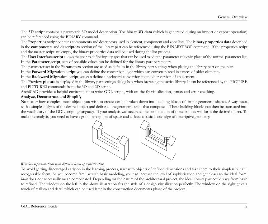
General Overview
GDL Reference Guide 2
The 3D script contains a parametric 3D model description. The binary 3D data (which is generated during an import or export operation)can be referenced using the BINARY command.The Properties script contains components and descriptors used in element, component and zone lists. The binary properties data describedin the components and descriptors section of the library part can be referenced using the BINARYPROP command. If the properties scriptand the master script are empty, the binary properties data will be used during the list process.The User Interface script allows the user to define input pages that can be used to edit the parameter values in place of the normal parameter list.In the Parameter script, sets of possible values can be defined for the library part parameters.The parameter set in the Parameters section are used as defaults in the library part settings when placing the library part on the plan.In the Forward Migration script you can define the conversion logic which can convert placed instances of older elements.In the Backward Migration script you can define a backward conversion to an older version of an element.The Preview picture is displayed in the library part settings dialog box when browsing the active library. It can be referenced by the PICTUREand PICTURE2 commands from the 3D and 2D script.ArchiCAD provides a helpful environment to write GDL scripts, with on-the-fly visualization, syntax and error checking.Analyze, Deconstruct and SimplifyNo matter how complex, most objects you wish to create can be broken down into building blocks of simple geometric shapes. Always startwith a simple analysis of the desired object and define all the geometric units that compose it. These building blocks can then be translated intothe vocabulary of the GDL scripting language. If your analysis was accurate, the combination of these entities will form the desired object. Tomake the analysis, you need to have a good perception of space and at least a basic knowledge of descriptive geometry.
Window representations with different levels of sophisticationTo avoid getting discouraged early on in the learning process, start with objects of defined dimensions and take them to their simplest but stillrecognizable form. As you become familiar with basic modeling, you can increase the level of sophistication and get closer to the ideal form.Ideal does not necessarily mean complicated. Depending on the nature of the architectural project, the ideal library part could vary from basicto refined. The window on the left in the above illustration fits the style of a design visualization perfectly. The window on the right gives atouch of realism and detail which can be used later in the construction documents phase of the project.
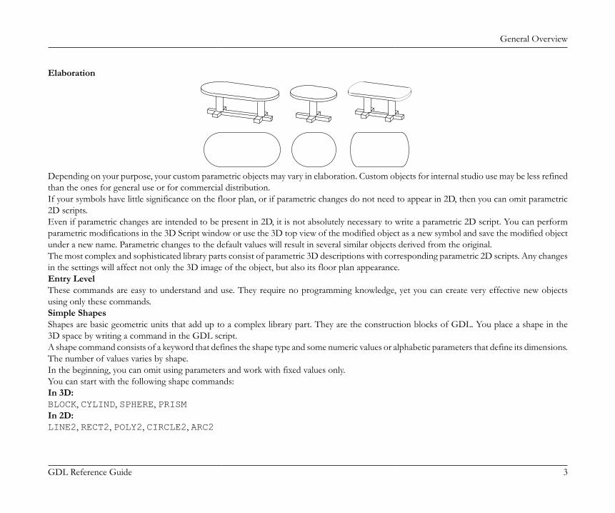
General Overview
GDL Reference Guide 3
Elaboration
Depending on your purpose, your custom parametric objects may vary in elaboration. Custom objects for internal studio use may be less refinedthan the ones for general use or for commercial distribution.If your symbols have little significance on the floor plan, or if parametric changes do not need to appear in 2D, then you can omit parametric2D scripts.Even if parametric changes are intended to be present in 2D, it is not absolutely necessary to write a parametric 2D script. You can performparametric modifications in the 3D Script window or use the 3D top view of the modified object as a new symbol and save the modified objectunder a new name. Parametric changes to the default values will result in several similar objects derived from the original.The most complex and sophisticated library parts consist of parametric 3D descriptions with corresponding parametric 2D scripts. Any changesin the settings will affect not only the 3D image of the object, but also its floor plan appearance.Entry LevelThese commands are easy to understand and use. They require no programming knowledge, yet you can create very effective new objectsusing only these commands.Simple ShapesShapes are basic geometric units that add up to a complex library part. They are the construction blocks of GDL. You place a shape in the3D space by writing a command in the GDL script.A shape command consists of a keyword that defines the shape type and some numeric values or alphabetic parameters that define its dimensions.The number of values varies by shape.In the beginning, you can omit using parameters and work with fixed values only.You can start with the following shape commands:In 3D:BLOCK, CYLIND, SPHERE, PRISMIn 2D:LINE2, RECT2, POLY2, CIRCLE2, ARC2
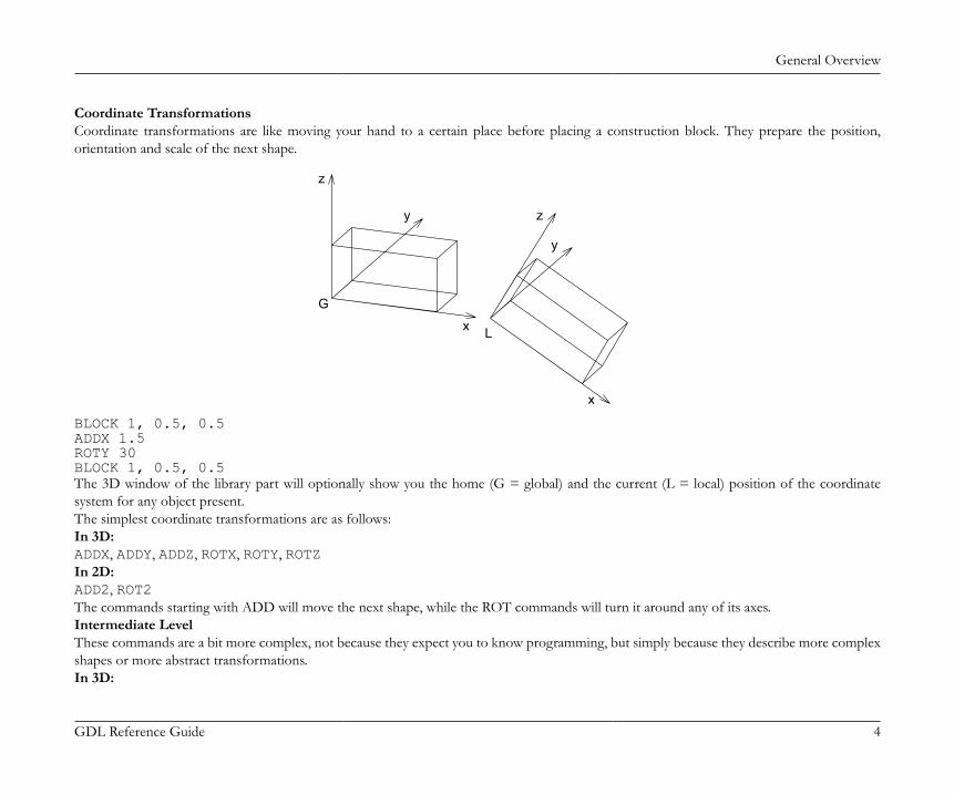
General Overview
GDL Reference Guide 4
Coordinate TransformationsCoordinate transformations are like moving your hand to a certain place before placing a construction block. They prepare the position,orientation and scale of the next shape.
L
G
x
y
z
x
y
z
BLOCK 1, 0.5, 0.5ADDX 1.5ROTY 30BLOCK 1, 0.5, 0.5The 3D window of the library part will optionally show you the home (G = global) and the current (L = local) position of the coordinatesystem for any object present.The simplest coordinate transformations are as follows:In 3D:ADDX, ADDY, ADDZ, ROTX, ROTY, ROTZIn 2D:ADD2, ROT2The commands starting with ADD will move the next shape, while the ROT commands will turn it around any of its axes.Intermediate LevelThese commands are a bit more complex, not because they expect you to know programming, but simply because they describe more complexshapes or more abstract transformations.In 3D:
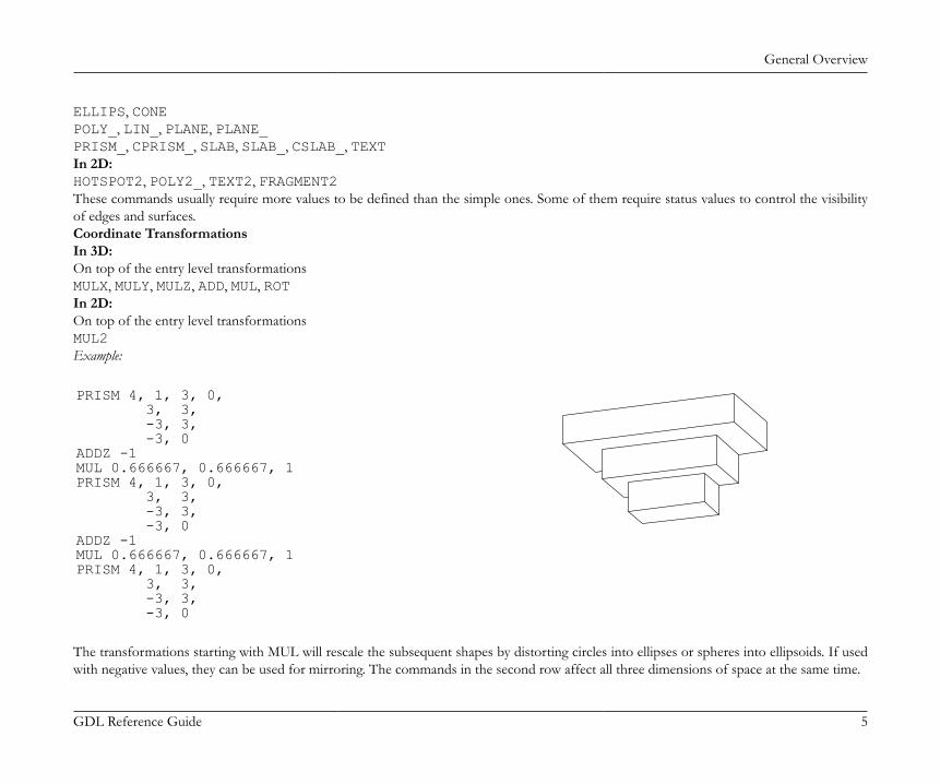
General Overview
GDL Reference Guide 5
ELLIPS, CONEPOLY_, LIN_, PLANE, PLANE_PRISM_, CPRISM_, SLAB, SLAB_, CSLAB_, TEXTIn 2D:HOTSPOT2, POLY2_, TEXT2, FRAGMENT2These commands usually require more values to be defined than the simple ones. Some of them require status values to control the visibilityof edges and surfaces.Coordinate TransformationsIn 3D:On top of the entry level transformationsMULX, MULY, MULZ, ADD, MUL, ROTIn 2D:On top of the entry level transformationsMUL2Example:
PRISM 4, 1, 3, 0, 3, 3, -3, 3, -3, 0ADDZ -1MUL 0.666667, 0.666667, 1PRISM 4, 1, 3, 0, 3, 3, -3, 3, -3, 0ADDZ -1MUL 0.666667, 0.666667, 1PRISM 4, 1, 3, 0, 3, 3, -3, 3, -3, 0
The transformations starting with MUL will rescale the subsequent shapes by distorting circles into ellipses or spheres into ellipsoids. If usedwith negative values, they can be used for mirroring. The commands in the second row affect all three dimensions of space at the same time.
General Overview
GDL Reference Guide 6
Advanced LevelThese commands add a new level of complexity either because of their geometric shape, or because they represent GDL as a programminglanguage.In 3D:
BPRISM_ BWALL_ CWALL_ XWALL_
CROOF_ FPRISM_ SPRISM_
EXTRUDE PYRAMID REVOLVE RULED
SWEEP TUBE TUBEA COONS
MESH MASS
LIGHT PICTURE
There are shape commands in this group which let you trace a spatial polygon with a base polygon to make smooth curved surfaces. Someshapes require material references in their parameter list.By using cutting planes, polygons and shapes, you can generate complex arbitrary shapes out of simple shapes. The corresponding commandsare CUTPLANE, CUTPOLY, CUTPOLYA, CUTSHAPE and CUTEND.In 2D:PICTURE2, POLY2_A, SPLINE2, SPLINE2AFlow Control and Conditional StatementsFOR - TO - NEXTDO - WHILE, WHILE - ENDWHILEREPEAT - UNTILIF - THEN - ELSE - ENDIFGOTO, GOSUBRETURN, END / EXITThese commands should be familiar to anyone who has ever programmed a computer, but they are basic enough that you can understandthem without prior programming experience.They let you make repetitive script parts to place several shapes with little scripting, or let you make decisions based on prior calculations.
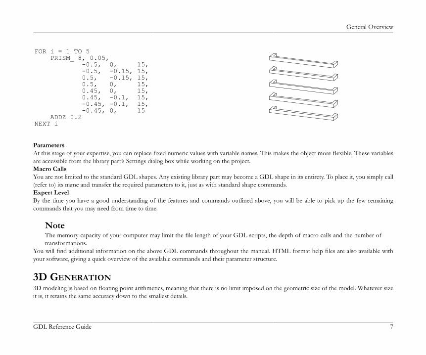
General Overview
GDL Reference Guide 7
FOR i = 1 TO 5 PRISM_ 8, 0.05, -0.5, 0, 15, -0.5, -0.15, 15, 0.5, -0.15, 15, 0.5, 0, 15, 0.45, 0, 15, 0.45, -0.1, 15, -0.45, -0.1, 15, -0.45, 0, 15 ADDZ 0.2NEXT i
ParametersAt this stage of your expertise, you can replace fixed numeric values with variable names. This makes the object more flexible. These variablesare accessible from the library part’s Settings dialog box while working on the project.Macro CallsYou are not limited to the standard GDL shapes. Any existing library part may become a GDL shape in its entirety. To place it, you simply call(refer to) its name and transfer the required parameters to it, just as with standard shape commands.Expert LevelBy the time you have a good understanding of the features and commands outlined above, you will be able to pick up the few remainingcommands that you may need from time to time.
NoteThe memory capacity of your computer may limit the file length of your GDL scripts, the depth of macro calls and the number oftransformations.
You will find additional information on the above GDL commands throughout the manual. HTML format help files are also available withyour software, giving a quick overview of the available commands and their parameter structure.
3D GENERATION3D modeling is based on floating point arithmetics, meaning that there is no limit imposed on the geometric size of the model. Whatever sizeit is, it retains the same accuracy down to the smallest details.
General Overview
GDL Reference Guide 8
The 3D model that you finally see on the screen is composed of geometric primitives. These primitives are stored in the memory of yourcomputer in binary format, and the 3D engine generates them according to the floor plan you created. The metamorphosis between thearchitectural floor plan elements and the binary 3D data is called 3D conversion.The primitives are the following:• all the vertices of your building components• all the edges linking the vertices• all the surface polygons within the edgesGroups of these primitives are kept together as bodies. The bodies make up the 3D model. All of the features of 3D visualization - smoothsurfaces, cast shadows, glossy or transparent materials - are based on this data structure.The 3D SpaceThe 3D model is created in three-dimensional space measured by the x, y and z axes of a master coordinate system whose origin is calledthe global origin.In Floor Plan view, you can see the global origin in the lower left corner of the worksheet if you open the program without reading a specificdocument. In addition, the global origin defines the zero level of all the stories referred to in a floor plan document.When you place an object into the design, the floor plan position will define its location along the x and y axes of this master coordinate system.The location along the z axis can be set in the Object Settings dialog box or directly adjusted when placed in 3D. This location will be the baseand the default position of the local coordinate system of the object. The shapes described in the script will be positioned with referenceto this local coordinate system.Coordinate TransformationsEvery GDL shape is linked to the current position of the local coordinate system. For example, blocks are linked to the origin. The length,width and height of the block are always measured in a positive direction along the three axes. Thus, the BLOCK command requires only threeparameters defining its dimensions along the axes.How can you generate a shifted and rotated block? With the parameter structure of the BLOCK there is no way to do this. It does not haveparameters for shift and rotation.The answer is to move the coordinate system to the correct position before issuing the BLOCK command. With the coordinate transformationcommands, you can pre-define its position and rotation around the axes. These transformations are not applied to the shapes already generatedand are only effective on subsequent shapes.The GDL InterpreterWhen a GDL script is executed, the GDL interpreter engine will detect the location, size, rotation angle, user defined parameters and themirrored state of the library part. It will then move the local coordinate system to the right position, ready to receive the GDL commandsfrom the script of the library parts. Every time a command for a basic shape is read by the interpreter, it will generate the geometric primitivesthat make up that particular shape.
General Overview
GDL Reference Guide 9
When the interpreter has finished, the complete binary 3D model will be stored in the memory, and you can perform 3D projections, fly-through renderings or sun studies on it.ArchiCAD contains a pre-compiler and an interpreter for GDL. Interpretation of a GDL script uses the pre-compiled code. This featureincreases speed of the analysis. If the GDL script is modified, a new code is generated.Data structures converted from other file formats (e.g., DXF, Zoom, Alias Wavefront) are stored in a binary 3D section of the library parts.This section is referenced by the BINARY command from the GDL script.The GDL Script AnalysisUsers have no control over the order in which library parts placed on the floor plan are analyzed. The order of GDL script analysis is basedon the internal data structure; moreover, Undo and Redo operations as well as modifications may influence that order. The only exceptions tothis rule are special GDL scripts of the active library, whose names begin with "MASTER_GDL" or "MASTEREND_GDL".Scripts whose name begins with "MASTER_GDL" are executed before a 3D conversion, before creating a Section/Elevation, before startinga list process and after loading the active library.Scripts whose name begins with "MASTEREND_GDL" are executed after a 3D conversion sequence, after creating a Section/Elevation, whenfinishing a list process and when the active library is to be changed (Load Libraries, Open a project, New project, Quit).These scripts are not executed when you edit library parts. If your library contains one or more such scripts they will all be executed in anorder that is not defined.MASTER_GDL and MASTEREND_GDL scripts can include attribute definitions, initializations of GDL user global variables, 3D commands(effective only in the 3D model), value list definitions (see the VALUES command) and GDL extension-specific commands. The attributesdefined in these scripts will be merged into the current attribute set (attributes with same names are not replaced, while attributes originatedfrom GDL and not edited in the program are always replaced).
GDL Syntax
GDL Reference Guide 10
GDL SYNTAXThis chapter presents the basic elements of GDL syntax, including statements, labels, identifiers, variables and parameters. Typographic rules are also explained in detail.
RULES OF GDL SYNTAXGDL is not case sensitive; uppercase and lowercase letters are not distinguished, except in strings placed between quotation marks. The logicalend of a GDL script is denoted by an END / EXIT statement or the physical end of the script.
STATEMENTSA GDL program consists of statements. A statement can start with a keyword (defining a GDL shape, coordinate transformations or programcontrol flow), with a macro name, or with a variable name followed by an '=' sign and an expression.
LINEThe statements are in lines separated by line-separators (end_of_line characters).A comma (,) in the last position indicates that the statement continues on the next line. A colon (:) is used for separating GDL statements ina line. After an exclamation mark (!) you can write any comment in the line. Blank lines can be inserted into a GDL script with no effect atall. Any number of spaces or tabs can be used between the operands and operators. The use of a space or tab is obligatory after statementkeywords and macro calls.
LABELAny line can start with a label which is used as a reference for a subsequent statement. A label is an integer number or a constant string betweenquotation marks, followed by a colon (:). A string label is case sensitive. Labels are checked for single occurrence. The execution of the programcan be continued from any label by using a GOTO or GOSUB statement.
CHARACTERSThe GDL text is composed of the lower and uppercase letters of the English alphabet, any number and the following characters:<space> _(underline) ~ ! : , ; . + - * / ^ = < > <= >= # ( ) [ ] { } \ @ & |(verticalbar) " ' ` ´ “ ” ’ ‘ <end_of_line>
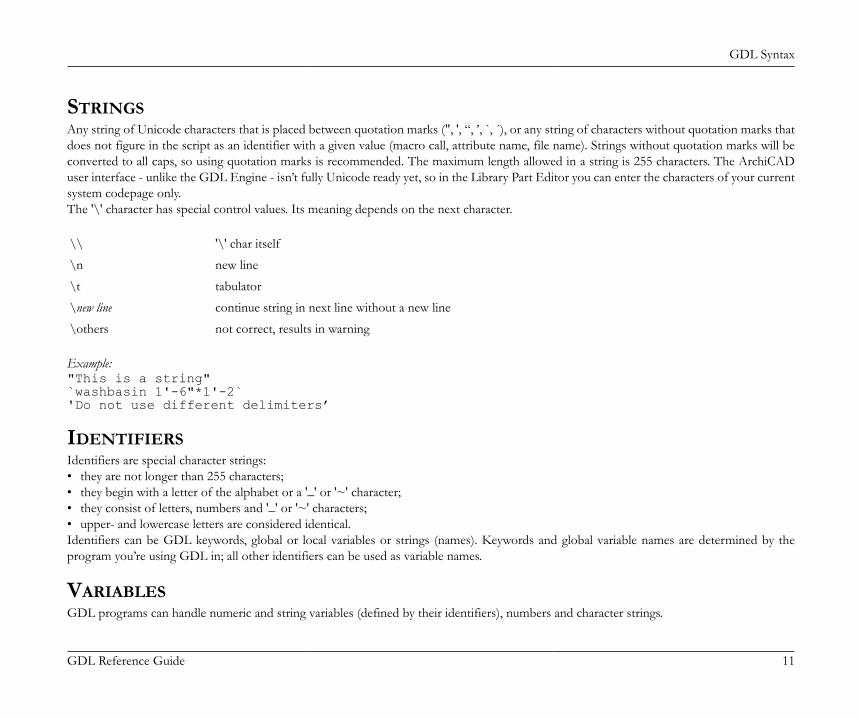
GDL Syntax
GDL Reference Guide 11
STRINGSAny string of Unicode characters that is placed between quotation marks (", ', “, ’, `, ´), or any string of characters without quotation marks thatdoes not figure in the script as an identifier with a given value (macro call, attribute name, file name). Strings without quotation marks will beconverted to all caps, so using quotation marks is recommended. The maximum length allowed in a string is 255 characters. The ArchiCADuser interface - unlike the GDL Engine - isn’t fully Unicode ready yet, so in the Library Part Editor you can enter the characters of your currentsystem codepage only.The '\' character has special control values. Its meaning depends on the next character.
\\ '\' char itself
\n new line
\t tabulator
\new line continue string in next line without a new line
\others not correct, results in warning
Example:"This is a string"`washbasin 1'-6"*1'-2`'Do not use different delimiters’
IDENTIFIERSIdentifiers are special character strings:• they are not longer than 255 characters;• they begin with a letter of the alphabet or a '_' or '~' character;• they consist of letters, numbers and '_' or '~' characters;• upper- and lowercase letters are considered identical.Identifiers can be GDL keywords, global or local variables or strings (names). Keywords and global variable names are determined by theprogram you’re using GDL in; all other identifiers can be used as variable names.
VARIABLESGDL programs can handle numeric and string variables (defined by their identifiers), numbers and character strings.
GDL Syntax
GDL Reference Guide 12
There are two sets of variables: local and global.All identifiers that are not keywords, global variables, attribute names, macro names or file names are considered local variables. If leftuninitialized (undefined), their value will be 0 (integer). Local variables are stacked with macro calls. When returning from a macro call, theinterpreter restores their values.Global variables have reserved names (for the list of global variables see the section called “Global Variables”). They are not stacked during macro calls,enabling the user to store special values of the modeling and to simulate return codes from macros. The user global variables can be set in anyscript but they will only be effective in subsequent scripts. If you want to make sure that the desired script is analyzed first, set these variablesin the MASTER_GDL library part. The other global variables can be used in your scripts to communicate with the program. By using the "="command, you can assign a numeric or string value to local and global variables.
PARAMETERSIdentifiers listed in a library part’s parameter list are called parameters. Parameter identifiers must not exceed 31 characters in length. And themaximum number of parameters must not exceed 1024. Within a script, the same rules apply to parameters as to local variables.Parameters of text-only GDL files are identified by letters A to Z.
SIMPLE TYPESVariables, parameters and expressions can be of two simple types: numeric or string.Numeric expressions are constant numbers, numeric variables or parameters, functions that return numeric values, and any combination of these inoperations. Numeric expressions can be integer or real. Integer expressions are integer constants, variables or parameters, functions that returninteger values, and any combination of these in operations which results in integers. Real expressions are real constants, variables or parameters,functions that return real values, and any combination of these (or integer expressions) in operations which results in reals. A numeric expressionbeing an integer or a real is determined during the compilation process and depends only on the constants, variables, parameters and theoperations used to combine them. Real and integer expressions can be used the same way at any place where a numeric expression is required,however, in cases where a combination of these may result in precision problems, a compiler warning appears (comparison of reals or reals andintegers using relational operators '=' or '<>', or boolean operators AND, OR, EXOR; IF or GOTO statements with real label expressions).String expressions are constant strings, string variables or parameters, functions that return strings, and any combination of these in operationswhich result in strings.
DERIVED TYPESVariables and parameters can also be arrays, and parameters can be value lists of a simple type.Arrays are one- or two-dimensional tables of numeric and/or string values, which can be accessed directly by indexes.
GDL Syntax
GDL Reference Guide 13
Value lists are sets of possible numeric or string values. They can be assigned to the parameters in the value list script of the library part or inthe MASTER_GDL script, and will appear in the parameter list as a pop-up menu.
CONVENTIONS USED IN THIS BOOK[aaa]Square brackets mean that the enclosed elements are optional (if they are bold, they must be entered as shown).{n}command version number...Previous element may be repeated|Exclusive or relation between parameters of a commandvariableAny GDL variable namepromptAny character string (must not contain quote character)bold_stringUPPERCASE_STRINGspecial charactersMust be entered as shownother_lowercase_string_in_parameter_listAny GDL expression
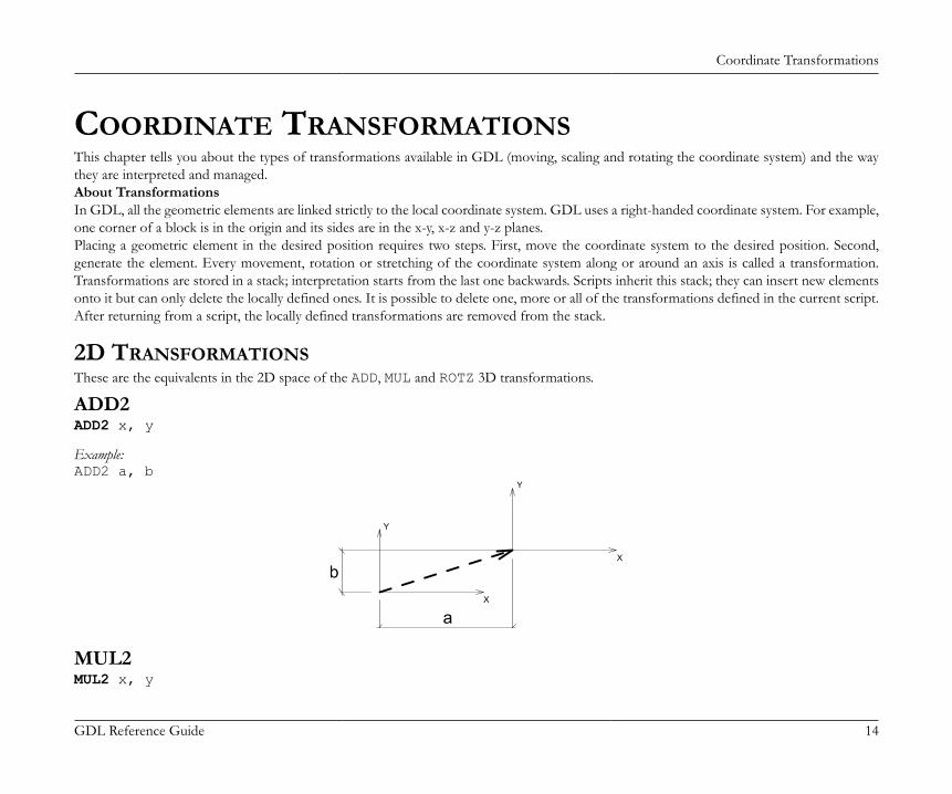
Coordinate Transformations
GDL Reference Guide 14
COORDINATE TRANSFORMATIONSThis chapter tells you about the types of transformations available in GDL (moving, scaling and rotating the coordinate system) and the waythey are interpreted and managed.About TransformationsIn GDL, all the geometric elements are linked strictly to the local coordinate system. GDL uses a right-handed coordinate system. For example,one corner of a block is in the origin and its sides are in the x-y, x-z and y-z planes.Placing a geometric element in the desired position requires two steps. First, move the coordinate system to the desired position. Second,generate the element. Every movement, rotation or stretching of the coordinate system along or around an axis is called a transformation.Transformations are stored in a stack; interpretation starts from the last one backwards. Scripts inherit this stack; they can insert new elementsonto it but can only delete the locally defined ones. It is possible to delete one, more or all of the transformations defined in the current script.After returning from a script, the locally defined transformations are removed from the stack.
2D TRANSFORMATIONSThese are the equivalents in the 2D space of the ADD, MUL and ROTZ 3D transformations.
ADD2ADD2 x, y
Example:ADD2 a, b
X
Y
X
Y
b
a
MUL2MUL2 x, y
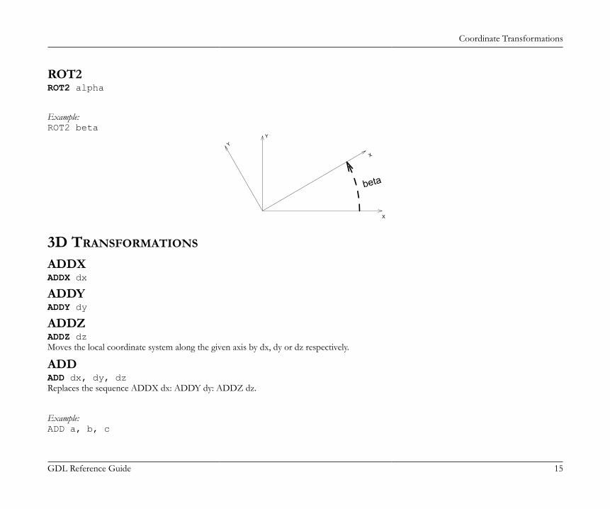
Coordinate Transformations
GDL Reference Guide 15
ROT2ROT2 alpha
Example:ROT2 beta
X
Y
X
Y
beta
3D TRANSFORMATIONS
ADDXADDX dx
ADDYADDY dy
ADDZADDZ dzMoves the local coordinate system along the given axis by dx, dy or dz respectively.
ADDADD dx, dy, dzReplaces the sequence ADDX dx: ADDY dy: ADDZ dz.
Example:ADD a, b, c
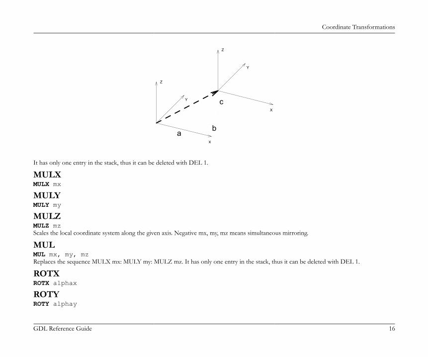
Coordinate Transformations
GDL Reference Guide 16
c
b
Z
a
Z
Y
Y
X
X
It has only one entry in the stack, thus it can be deleted with DEL 1.
MULXMULX mx
MULYMULY my
MULZMULZ mzScales the local coordinate system along the given axis. Negative mx, my, mz means simultaneous mirroring.
MULMUL mx, my, mzReplaces the sequence MULX mx: MULY my: MULZ mz. It has only one entry in the stack, thus it can be deleted with DEL 1.
ROTXROTX alphax
ROTYROTY alphay
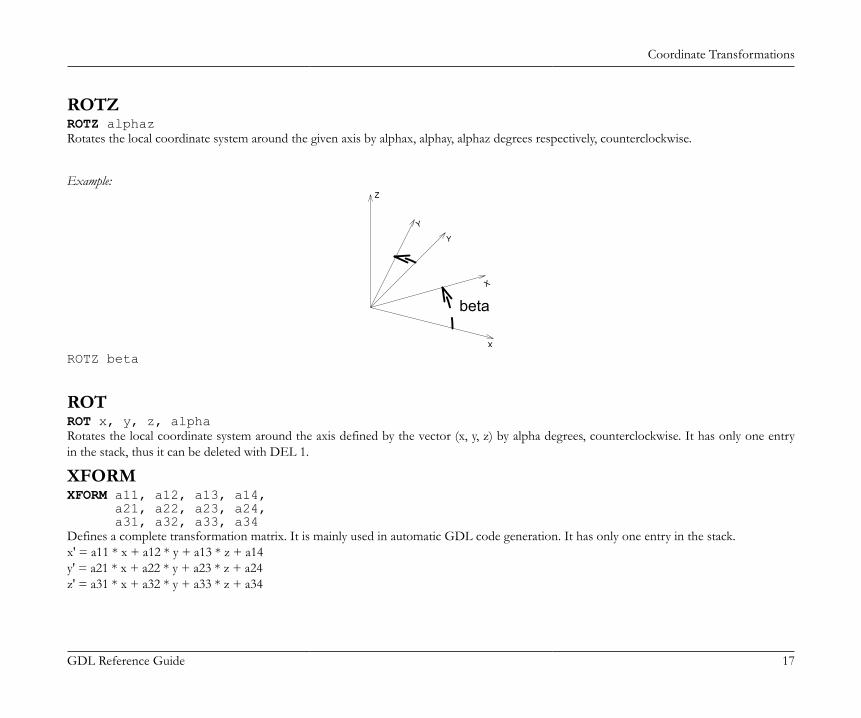
Coordinate Transformations
GDL Reference Guide 17
ROTZROTZ alphazRotates the local coordinate system around the given axis by alphax, alphay, alphaz degrees respectively, counterclockwise.
Example:
Y
X
X
Z
Y
beta
ROTZ beta
ROTROT x, y, z, alphaRotates the local coordinate system around the axis defined by the vector (x, y, z) by alpha degrees, counterclockwise. It has only one entryin the stack, thus it can be deleted with DEL 1.
XFORMXFORM a11, a12, a13, a14, a21, a22, a23, a24, a31, a32, a33, a34Defines a complete transformation matrix. It is mainly used in automatic GDL code generation. It has only one entry in the stack.x' = a11 * x + a12 * y + a13 * z + a14y' = a21 * x + a22 * y + a23 * z + a24z' = a31 * x + a32 * y + a33 * z + a34
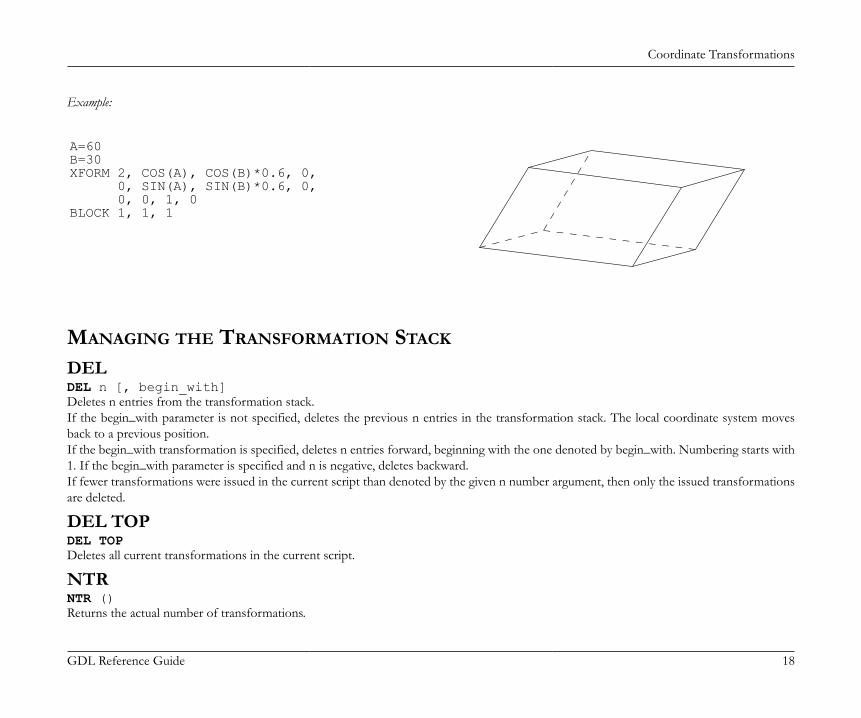
Coordinate Transformations
GDL Reference Guide 18
Example:
A=60B=30XFORM 2, COS(A), COS(B)*0.6, 0, 0, SIN(A), SIN(B)*0.6, 0, 0, 0, 1, 0BLOCK 1, 1, 1
MANAGING THE TRANSFORMATION STACK
DELDEL n [, begin_with]Deletes n entries from the transformation stack.If the begin_with parameter is not specified, deletes the previous n entries in the transformation stack. The local coordinate system movesback to a previous position.If the begin_with transformation is specified, deletes n entries forward, beginning with the one denoted by begin_with. Numbering starts with1. If the begin_with parameter is specified and n is negative, deletes backward.If fewer transformations were issued in the current script than denoted by the given n number argument, then only the issued transformationsare deleted.
DEL TOPDEL TOPDeletes all current transformations in the current script.
NTRNTR ()Returns the actual number of transformations.
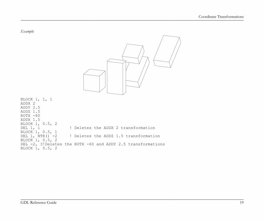
Coordinate Transformations
GDL Reference Guide 19
Example:
BLOCK 1, 1, 1ADDX 2ADDY 2.5ADDZ 1.5ROTX -60ADDX 1.5BLOCK 1, 0.5, 2DEL 1, 1 ! Deletes the ADDX 2 transformationBLOCK 1, 0.5, 1DEL 1, NTR() -2 ! Deletes the ADDZ 1.5 transformationBLOCK 1, 0.5, 2DEL -2, 3!Deletes the ROTX -60 and ADDY 2.5 transformationsBLOCK 1, 0.5, 2
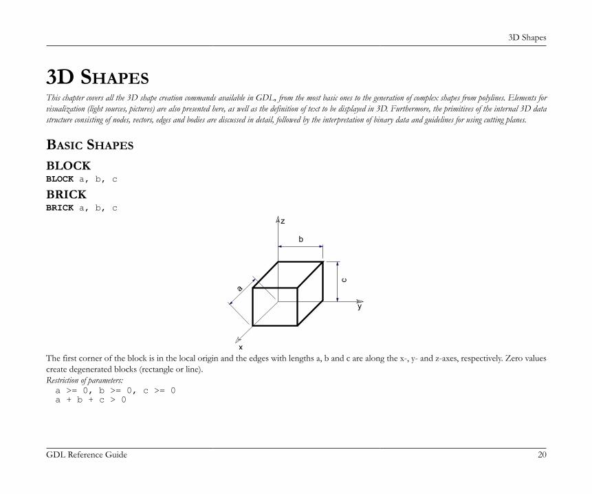
3D Shapes
GDL Reference Guide 20
3D SHAPESThis chapter covers all the 3D shape creation commands available in GDL, from the most basic ones to the generation of complex shapes from polylines. Elements forvisualization (light sources, pictures) are also presented here, as well as the definition of text to be displayed in 3D. Furthermore, the primitives of the internal 3D datastructure consisting of nodes, vectors, edges and bodies are discussed in detail, followed by the interpretation of binary data and guidelines for using cutting planes.
BASIC SHAPES
BLOCKBLOCK a, b, c
BRICKBRICK a, b, c
x
y
z
b
ca
The first corner of the block is in the local origin and the edges with lengths a, b and c are along the x-, y- and z-axes, respectively. Zero valuescreate degenerated blocks (rectangle or line).Restriction of parameters:a >= 0, b >= 0, c >= 0a + b + c > 0
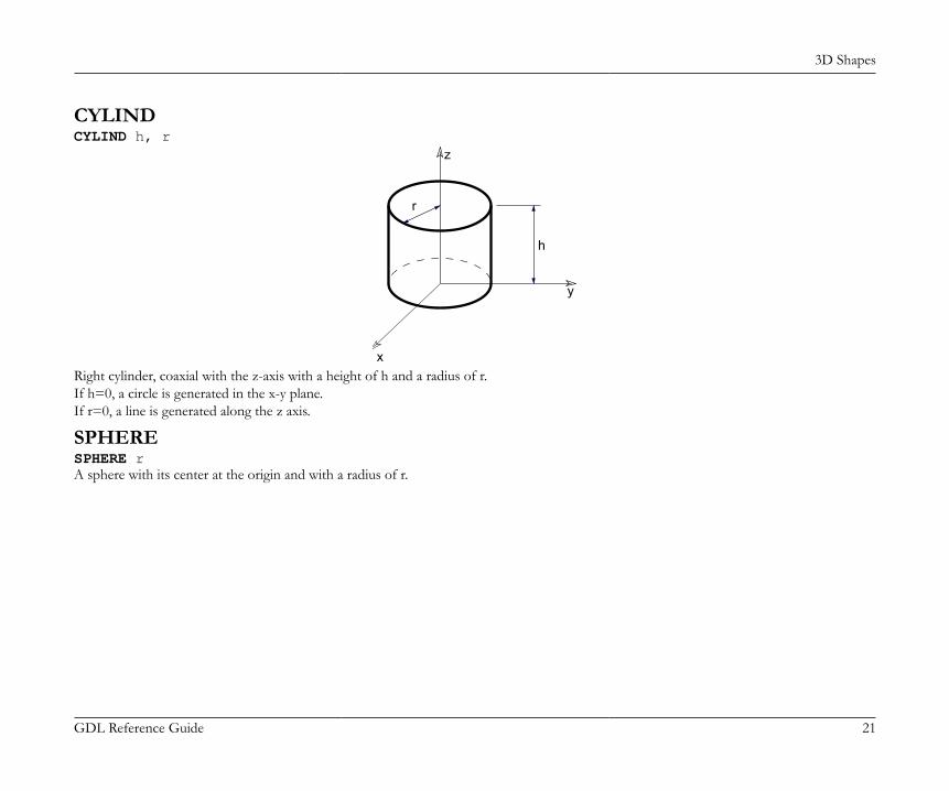
3D Shapes
GDL Reference Guide 21
CYLINDCYLIND h, r
x
y
z
r
h
Right cylinder, coaxial with the z-axis with a height of h and a radius of r.If h=0, a circle is generated in the x-y plane.If r=0, a line is generated along the z axis.
SPHERESPHERE rA sphere with its center at the origin and with a radius of r.
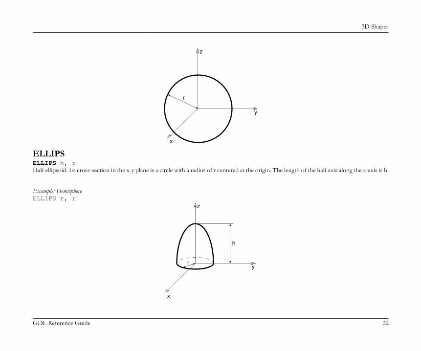
3D Shapes
GDL Reference Guide 22
x
y
z
r
ELLIPSELLIPS h, rHalf ellipsoid. Its cross-section in the x-y plane is a circle with a radius of r centered at the origin. The length of the half axis along the z-axis is h.
Example: HemisphereELLIPS r, r
x
y
z
h
r
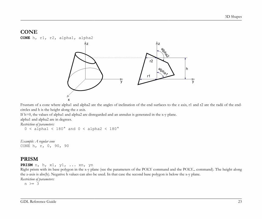
3D Shapes
GDL Reference Guide 23
CONECONE h, r1, r2, alpha1, alpha2
x
y
z
y
z
r1
r2
h
alpha2
alpha1
Frustum of a cone where alpha1 and alpha2 are the angles of inclination of the end surfaces to the z axis, r1 and r2 are the radii of the end-circles and h is the height along the z axis.If h=0, the values of alpha1 and alpha2 are disregarded and an annulus is generated in the x-y plane.alpha1 and alpha2 are in degrees.Restriction of parameters:0 < alpha1 < 180° and 0 < alpha2 < 180°
Example: A regular coneCONE h, r, 0, 90, 90
PRISMPRISM n, h, x1, y1, ... xn, ynRight prism with its base polygon in the x-y plane (see the parameters of the POLY command and the POLY_ command). The height alongthe z-axis is abs(h). Negative h values can also be used. In that case the second base polygon is below the x-y plane.Restriction of parameters:n >= 3
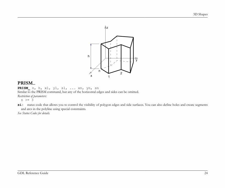
3D Shapes
GDL Reference Guide 24
x
y
z
h
n
12
PRISM_PRISM_ n, h, x1, y1, s1, ... xn, yn, snSimilar to the PRISM command, but any of the horizontal edges and sides can be omitted.Restriction of parameters:n >= 3
si: status code that allows you to control the visibility of polygon edges and side surfaces. You can also define holes and create segmentsand arcs in the polyline using special constraints.
See Status Codes for details.
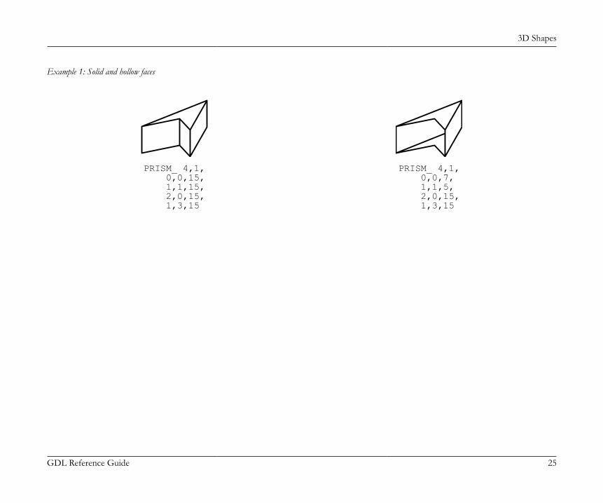
3D Shapes
GDL Reference Guide 25
Example 1: Solid and hollow faces
PRISM_ 4,1, 0,0,15, 1,1,15, 2,0,15, 1,3,15
PRISM_ 4,1, 0,0,7, 1,1,5, 2,0,15, 1,3,15
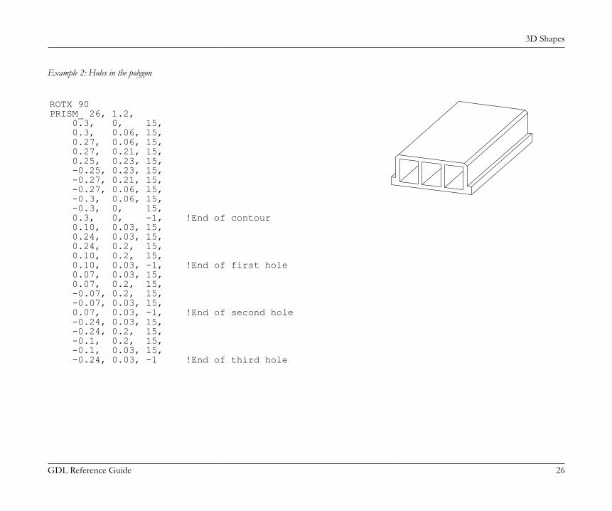
3D Shapes
GDL Reference Guide 26
Example 2: Holes in the polygon
ROTX 90PRISM_ 26, 1.2, 0.3, 0, 15, 0.3, 0.06, 15, 0.27, 0.06, 15, 0.27, 0.21, 15, 0.25, 0.23, 15, -0.25, 0.23, 15, -0.27, 0.21, 15, -0.27, 0.06, 15, -0.3, 0.06, 15, -0.3, 0, 15, 0.3, 0, -1, !End of contour 0.10, 0.03, 15, 0.24, 0.03, 15, 0.24, 0.2, 15, 0.10, 0.2, 15, 0.10, 0.03, -1, !End of first hole 0.07, 0.03, 15, 0.07, 0.2, 15, -0.07, 0.2, 15, -0.07, 0.03, 15, 0.07, 0.03, -1, !End of second hole -0.24, 0.03, 15, -0.24, 0.2, 15, -0.1, 0.2, 15, -0.1, 0.03, 15, -0.24, 0.03, -1 !End of third hole
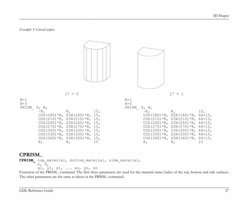
3D Shapes
GDL Reference Guide 27
Example 3: Curved surface
j7 = 0 j7 = 1
R=1H=3PRISM_ 9, H, -R, R, 15, COS(180)*R, SIN(180)*R, 15, COS(210)*R, SIN(210)*R, 15, COS(240)*R, SIN(240)*R, 15, COS(270)*R, SIN(270)*R, 15, COS(300)*R, SIN(300)*R, 15, COS(330)*R, SIN(330)*R, 15, COS(360)*R, SIN(360)*R, 15, R, R, 15
R=1H=3PRISM_ 9, H, -R, R, 15, COS(180)*R, SIN(180)*R, 64+15, COS(210)*R, SIN(210)*R, 64+15, COS(240)*R, SIN(240)*R, 64+15, COS(270)*R, SIN(270)*R, 64+15, COS(300)*R, SIN(300)*R, 64+15, COS(330)*R, SIN(330)*R, 64+15, COS(360)*R, SIN(360)*R, 64+15, R, R, 15
CPRISM_CPRISM_ top_material, bottom_material, side_material, n, h, x1, y1, s1, ... xn, yn, snExtension of the PRISM_ command. The first three parameters are used for the material name/index of the top, bottom and side surfaces.The other parameters are the same as above in the PRISM_ command.
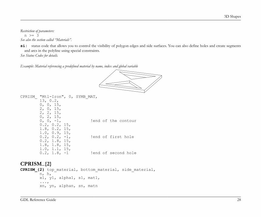
3D Shapes
GDL Reference Guide 28
Restriction of parameters:n >= 3
See also the section called “Materials”.si: status code that allows you to control the visibility of polygon edges and side surfaces. You can also define holes and create segments
and arcs in the polyline using special constraints.See Status Codes for details.
Example: Material referencing a predefined material by name, index and global variable
CPRISM_ "Mtl-Iron", 0, SYMB_MAT, 13, 0.2, 0, 0, 15, 2, 0, 15, 2, 2, 15, 0, 2, 15, 0, 0, -1, !end of the contour 0.2, 0.2, 15, 1.8, 0.2, 15, 1.0, 0.9, 15, 0.2, 0.2, -1, !end of first hole 0.2, 1.8, 15, 1.8, 1.8, 15, 1.0, 1.1, 15, 0.2, 1.8, -1 !end of second hole
CPRISM_{2}CPRISM_{2} top_material, bottom_material, side_material, n, h, x1, y1, alpha1, s1, mat1, ..., xn, yn, alphan, sn, matn
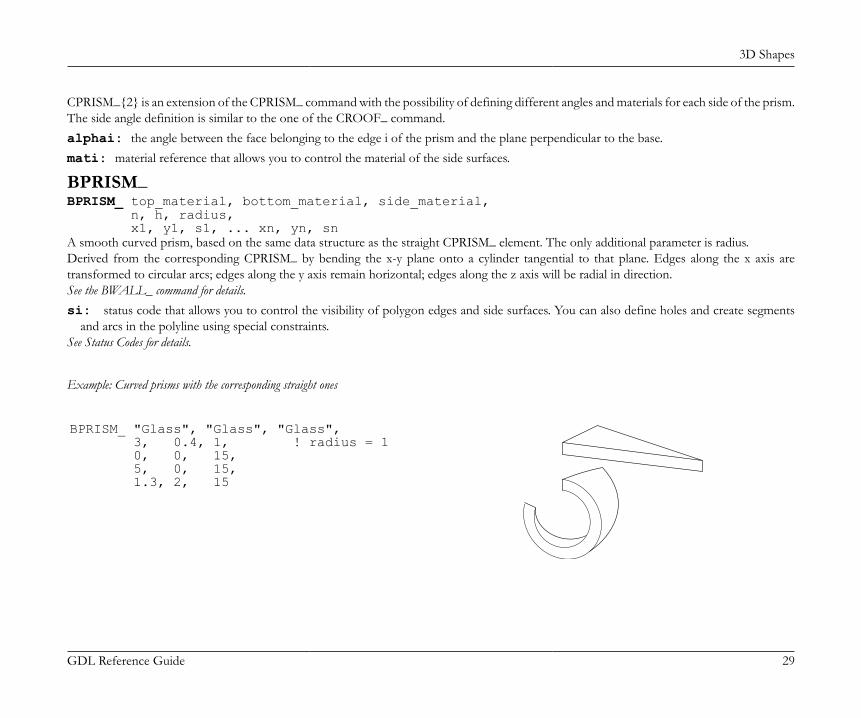
3D Shapes
GDL Reference Guide 29
CPRISM_{2} is an extension of the CPRISM_ command with the possibility of defining different angles and materials for each side of the prism.The side angle definition is similar to the one of the CROOF_ command.alphai: the angle between the face belonging to the edge i of the prism and the plane perpendicular to the base.mati: material reference that allows you to control the material of the side surfaces.
BPRISM_BPRISM_ top_material, bottom_material, side_material, n, h, radius, x1, y1, s1, ... xn, yn, snA smooth curved prism, based on the same data structure as the straight CPRISM_ element. The only additional parameter is radius.Derived from the corresponding CPRISM_ by bending the x-y plane onto a cylinder tangential to that plane. Edges along the x axis aretransformed to circular arcs; edges along the y axis remain horizontal; edges along the z axis will be radial in direction.See the BWALL_ command for details.si: status code that allows you to control the visibility of polygon edges and side surfaces. You can also define holes and create segments
and arcs in the polyline using special constraints.See Status Codes for details.
Example: Curved prisms with the corresponding straight ones
BPRISM_ "Glass", "Glass", "Glass", 3, 0.4, 1, ! radius = 1 0, 0, 15, 5, 0, 15, 1.3, 2, 15
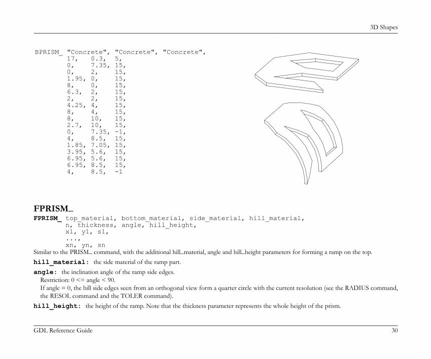
3D Shapes
GDL Reference Guide 30
BPRISM_ "Concrete", "Concrete", "Concrete", 17, 0.3, 5, 0, 7.35, 15, 0, 2, 15, 1.95, 0, 15, 8, 0, 15, 6.3, 2, 15, 2, 2, 15, 4.25, 4, 15, 8, 4, 15, 8, 10, 15, 2.7, 10, 15, 0, 7.35, -1, 4, 8.5, 15, 1.85, 7.05, 15, 3.95, 5.6, 15, 6.95, 5.6, 15, 6.95, 8.5, 15, 4, 8.5, -1
FPRISM_FPRISM_ top_material, bottom_material, side_material, hill_material, n, thickness, angle, hill_height, x1, y1, s1, ..., xn, yn, snSimilar to the PRISM_ command, with the additional hill_material, angle and hill_height parameters for forming a ramp on the top.hill_material: the side material of the ramp part.angle: the inclination angle of the ramp side edges.
Restriction: 0 <= angle < 90.If angle = 0, the hill side edges seen from an orthogonal view form a quarter circle with the current resolution (see the RADIUS command,the RESOL command and the TOLER command).
hill_height: the height of the ramp. Note that the thickness parameter represents the whole height of the prism.
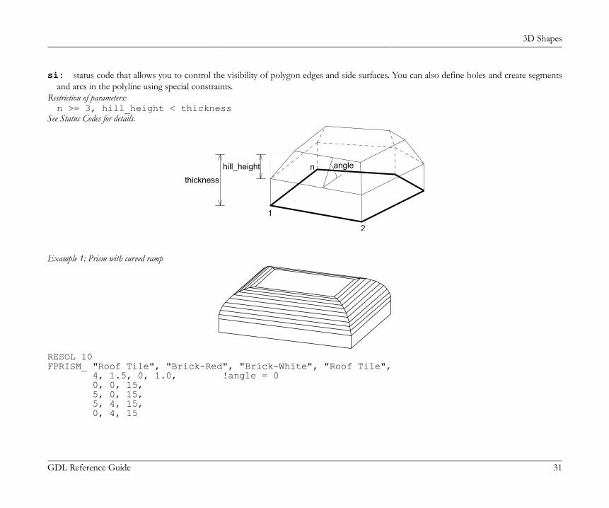
3D Shapes
GDL Reference Guide 31
si: status code that allows you to control the visibility of polygon edges and side surfaces. You can also define holes and create segmentsand arcs in the polyline using special constraints.
Restriction of parameters:n >= 3, hill_height < thickness
See Status Codes for details.
1
n
2
hill_heightthickness
angle
Example 1: Prism with curved ramp
RESOL 10FPRISM_ "Roof Tile", "Brick-Red", "Brick-White", "Roof Tile", 4, 1.5, 0, 1.0, !angle = 0 0, 0, 15, 5, 0, 15, 5, 4, 15, 0, 4, 15
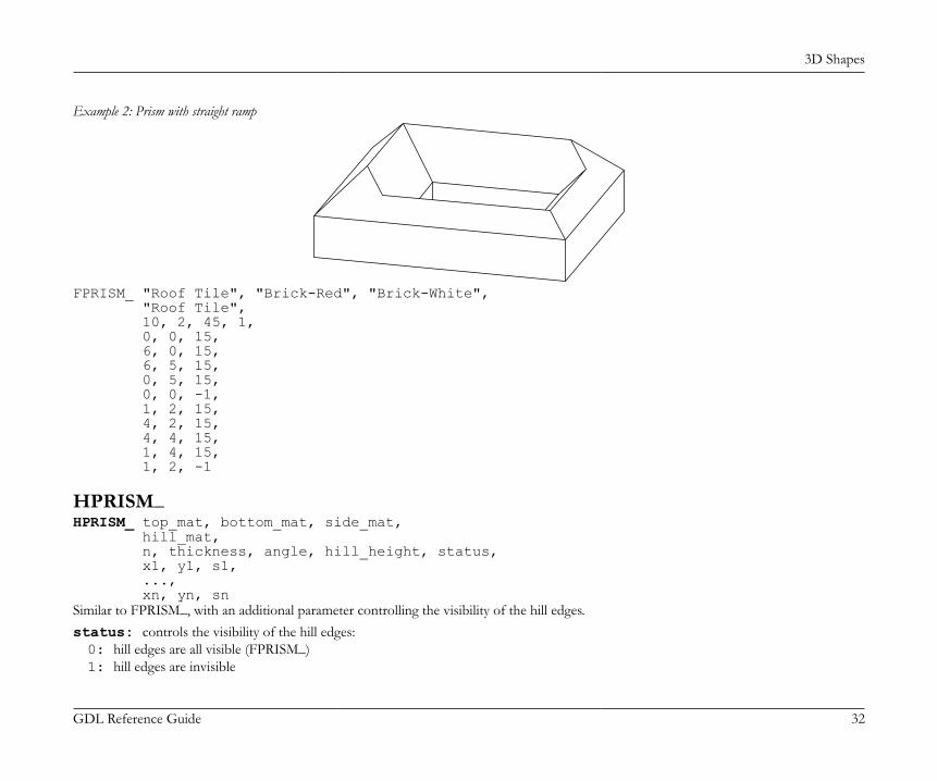
3D Shapes
GDL Reference Guide 32
Example 2: Prism with straight ramp
FPRISM_ "Roof Tile", "Brick-Red", "Brick-White", "Roof Tile", 10, 2, 45, 1, 0, 0, 15, 6, 0, 15, 6, 5, 15, 0, 5, 15, 0, 0, -1, 1, 2, 15, 4, 2, 15, 4, 4, 15, 1, 4, 15, 1, 2, -1
HPRISM_HPRISM_ top_mat, bottom_mat, side_mat, hill_mat, n, thickness, angle, hill_height, status, x1, y1, s1, ..., xn, yn, snSimilar to FPRISM_, with an additional parameter controlling the visibility of the hill edges.status: controls the visibility of the hill edges:0: hill edges are all visible (FPRISM_)1: hill edges are invisible
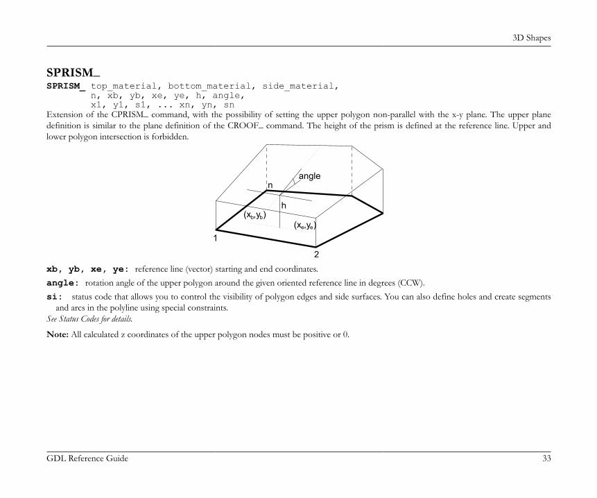
3D Shapes
GDL Reference Guide 33
SPRISM_SPRISM_ top_material, bottom_material, side_material, n, xb, yb, xe, ye, h, angle, x1, y1, s1, ... xn, yn, snExtension of the CPRISM_ command, with the possibility of setting the upper polygon non-parallel with the x-y plane. The upper planedefinition is similar to the plane definition of the CROOF_ command. The height of the prism is defined at the reference line. Upper andlower polygon intersection is forbidden.
n
h
1
2
(x ,y )b b(x ,y )ee
angle
xb, yb, xe, ye: reference line (vector) starting and end coordinates.angle: rotation angle of the upper polygon around the given oriented reference line in degrees (CCW).si: status code that allows you to control the visibility of polygon edges and side surfaces. You can also define holes and create segments
and arcs in the polyline using special constraints.See Status Codes for details.
Note: All calculated z coordinates of the upper polygon nodes must be positive or 0.
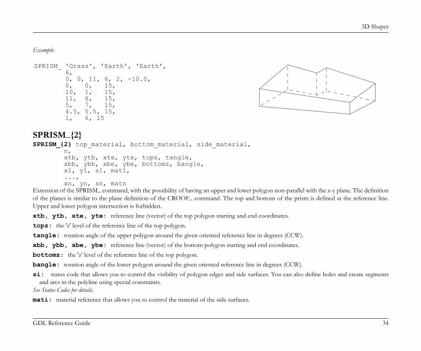
3D Shapes
GDL Reference Guide 34
Example:
SPRISM_ 'Grass', 'Earth', 'Earth', 6, 0, 0, 11, 6, 2, -10.0, 0, 0, 15, 10, 1, 15, 11, 6, 15, 5, 7, 15, 4.5, 5.5, 15, 1, 6, 15
SPRISM_{2}SPRISM_{2} top_material, bottom_material, side_material, n, xtb, ytb, xte, yte, topz, tangle, xbb, ybb, xbe, ybe, bottomz, bangle, x1, y1, s1, mat1, ..., xn, yn, sn, matnExtension of the SPRISM_ command, with the possibility of having an upper and lower polygon non-parallel with the x-y plane. The definitionof the planes is similar to the plane definition of the CROOF_ command. The top and bottom of the prism is defined at the reference line.Upper and lower polygon intersection is forbidden.xtb, ytb, xte, yte: reference line (vector) of the top polygon starting and end coordinates.topz: the 'z' level of the reference line of the top polygon.tangle: rotation angle of the upper polygon around the given oriented reference line in degrees (CCW).xbb, ybb, xbe, ybe: reference line (vector) of the bottom polygon starting and end coordinates.bottomz: the 'z' level of the reference line of the top polygon.bangle: rotation angle of the lower polygon around the given oriented reference line in degrees (CCW).si: status code that allows you to control the visibility of polygon edges and side surfaces. You can also define holes and create segments
and arcs in the polyline using special constraints.See Status Codes for details.mati: material reference that allows you to control the material of the side surfaces.
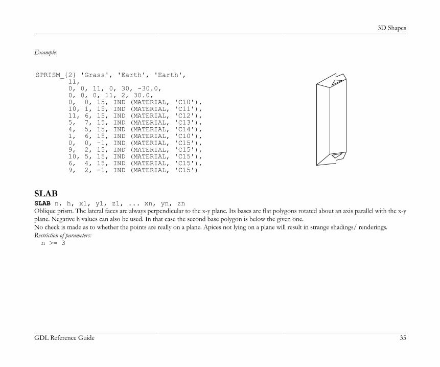
3D Shapes
GDL Reference Guide 35
Example:
SPRISM_{2} 'Grass', 'Earth', 'Earth', 11, 0, 0, 11, 0, 30, -30.0, 0, 0, 0, 11, 2, 30.0, 0, 0, 15, IND (MATERIAL, 'C10'), 10, 1, 15, IND (MATERIAL, 'C11'), 11, 6, 15, IND (MATERIAL, 'C12'), 5, 7, 15, IND (MATERIAL, 'C13'), 4, 5, 15, IND (MATERIAL, 'C14'), 1, 6, 15, IND (MATERIAL, 'C10'), 0, 0, -1, IND (MATERIAL, 'C15'), 9, 2, 15, IND (MATERIAL, 'C15'), 10, 5, 15, IND (MATERIAL, 'C15'), 6, 4, 15, IND (MATERIAL, 'C15'), 9, 2, -1, IND (MATERIAL, 'C15')
SLABSLAB n, h, x1, y1, z1, ... xn, yn, znOblique prism. The lateral faces are always perpendicular to the x-y plane. Its bases are flat polygons rotated about an axis parallel with the x-yplane. Negative h values can also be used. In that case the second base polygon is below the given one.No check is made as to whether the points are really on a plane. Apices not lying on a plane will result in strange shadings/ renderings.Restriction of parameters:n >= 3
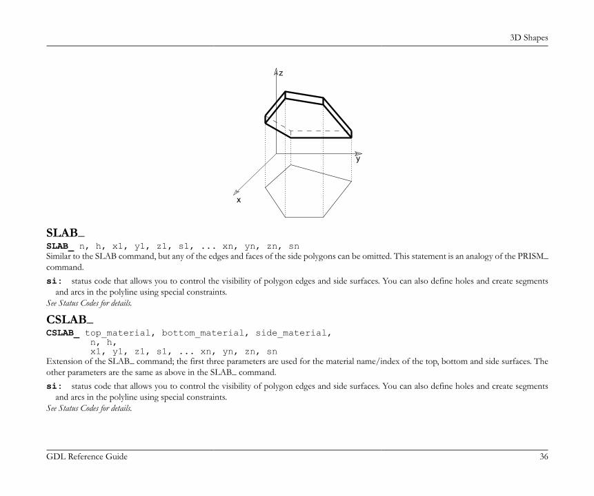
3D Shapes
GDL Reference Guide 36
x
y
z
SLAB_SLAB_ n, h, x1, y1, z1, s1, ... xn, yn, zn, snSimilar to the SLAB command, but any of the edges and faces of the side polygons can be omitted. This statement is an analogy of the PRISM_command.si: status code that allows you to control the visibility of polygon edges and side surfaces. You can also define holes and create segments
and arcs in the polyline using special constraints.See Status Codes for details.
CSLAB_CSLAB_ top_material, bottom_material, side_material, n, h, x1, y1, z1, s1, ... xn, yn, zn, snExtension of the SLAB_ command; the first three parameters are used for the material name/index of the top, bottom and side surfaces. Theother parameters are the same as above in the SLAB_ command.si: status code that allows you to control the visibility of polygon edges and side surfaces. You can also define holes and create segments
and arcs in the polyline using special constraints.See Status Codes for details.
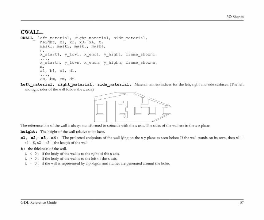
3D Shapes
GDL Reference Guide 37
CWALL_CWALL_ left_material, right_material, side_material, height, x1, x2, x3, x4, t, mask1, mask2, mask3, mask4, n, x_start1, y_low1, x_end1, y_high1, frame_shown1, ..., x_startn, y_lown, x_endn, y_highn, frame_shownn, m, a1, b1, c1, d1, ..., am, bm, cm, dmLeft_material, right_material, side_material: Material names/indices for the left, right and side surfaces. (The left
and right sides of the wall follow the x axis.)
The reference line of the wall is always transformed to coincide with the x axis. The sides of the wall are in the x-z plane.height: The height of the wall relative to its base.x1, x2, x3, x4: The projected endpoints of the wall lying on the x-y plane as seen below. If the wall stands on its own, then x1 =
x4 = 0, x2 = x3 = the length of the wall.t: the thickness of the wall.t < 0: if the body of the wall is to the right of the x axis,t > 0: if the body of the wall is to the left of the x axis,t = 0: if the wall is represented by a polygon and frames are generated around the holes.
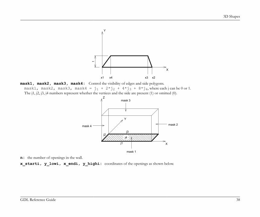
3D Shapes
GDL Reference Guide 38
x4 x2x3x1
Y
X
t
mask1, mask2, mask3, mask4: Control the visibility of edges and side polygons.mask1, mask2, mask3, mask4 = j1 + 2*j2 + 4*j3 + 8*j4, where each j can be 0 or 1.The j1, j2, j3, j4 numbers represent whether the vertices and the side are present (1) or omitted (0).
j4
j3
Z
X
Y
j1
mask 1
j2
mask 4 mask 2
mask 3
n: the number of openings in the wall.x_starti, y_lowi, x_endi, y_highi: coordinates of the openings as shown below.
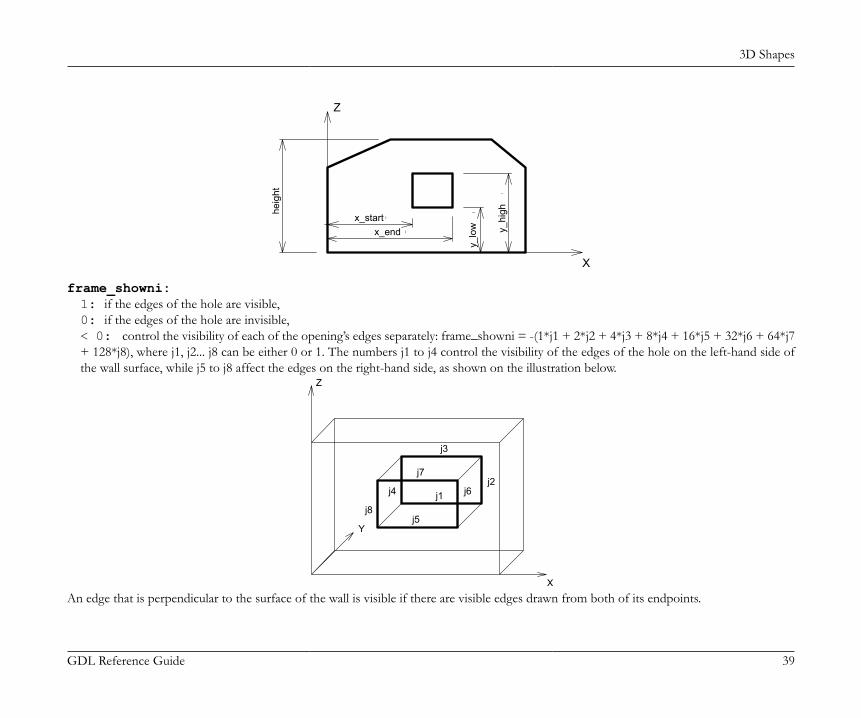
3D Shapes
GDL Reference Guide 39
X
Z
i
i
i
i
heig
ht
x_startx_end
y_lo
w y_hi
gh
frame_showni:1: if the edges of the hole are visible,0: if the edges of the hole are invisible,< 0: control the visibility of each of the opening’s edges separately: frame_showni = -(1*j1 + 2*j2 + 4*j3 + 8*j4 + 16*j5 + 32*j6 + 64*j7+ 128*j8), where j1, j2... j8 can be either 0 or 1. The numbers j1 to j4 control the visibility of the edges of the hole on the left-hand side ofthe wall surface, while j5 to j8 affect the edges on the right-hand side, as shown on the illustration below.
j4
j3
j1j2
j5
j7
j6
j8
Y
Z
XAn edge that is perpendicular to the surface of the wall is visible if there are visible edges drawn from both of its endpoints.
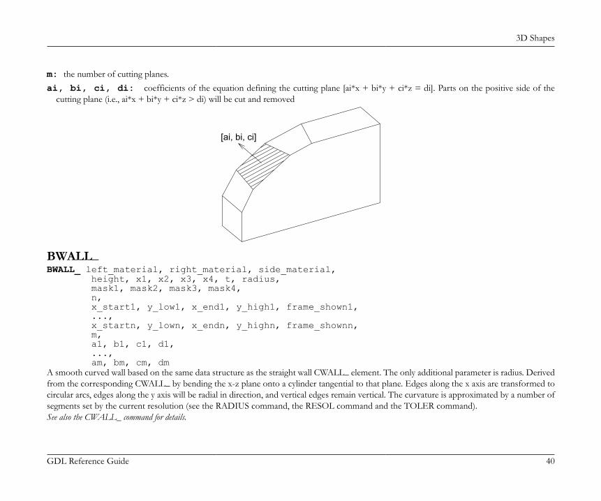
3D Shapes
GDL Reference Guide 40
m: the number of cutting planes.ai, bi, ci, di: coefficients of the equation defining the cutting plane [ai*x + bi*y + ci*z = di]. Parts on the positive side of the
cutting plane (i.e., ai*x + bi*y + ci*z > di) will be cut and removed
[ai, bi, ci]
BWALL_BWALL_ left_material, right_material, side_material, height, x1, x2, x3, x4, t, radius, mask1, mask2, mask3, mask4, n, x_start1, y_low1, x_end1, y_high1, frame_shown1, ..., x_startn, y_lown, x_endn, y_highn, frame_shownn, m, a1, b1, c1, d1, ..., am, bm, cm, dmA smooth curved wall based on the same data structure as the straight wall CWALL_ element. The only additional parameter is radius. Derivedfrom the corresponding CWALL_ by bending the x-z plane onto a cylinder tangential to that plane. Edges along the x axis are transformed tocircular arcs, edges along the y axis will be radial in direction, and vertical edges remain vertical. The curvature is approximated by a number ofsegments set by the current resolution (see the RADIUS command, the RESOL command and the TOLER command).See also the CWALL_ command for details.
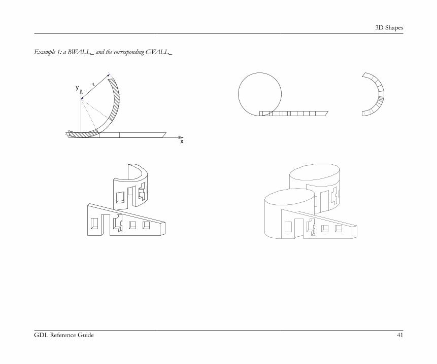
3D Shapes
GDL Reference Guide 41
Example 1: a BWALL_ and the corresponding CWALL_
y
x
r
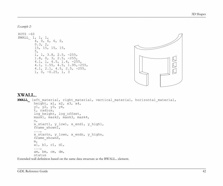
3D Shapes
GDL Reference Guide 42
Example 2:
ROTZ -60BWALL_ 1, 1, 1, 4, 0, 6, 6, 0, 0.3, 2, 15, 15, 15, 15, 5, 1, 1, 3.8, 2.5, -255, 1.8, 0, 3, 2.5, -255, 4.1, 1, 4.5, 1.4, -255, 4.1, 1.55, 4.5, 1.95,-255, 4.1, 2.1, 4.5, 2.5, -255, 1, 0, -0.25, 1, 3
XWALL_XWALL_ left_material, right_material, vertical_material, horizontal_material, height, x1, x2, x3, x4, y1, y2, y3, y4, t, radius, log_height, log_offset, mask1, mask2, mask3, mask4, n, x_start1, y_low1, x_end1, y_high1, frame_shown1, ..., x_startn, y_lown, x_endn, y_highn, frame_shownn, m, a1, b1, c1, d1, ..., am, bm, cm, dm, statusExtended wall definition based on the same data structure as the BWALL_ element.
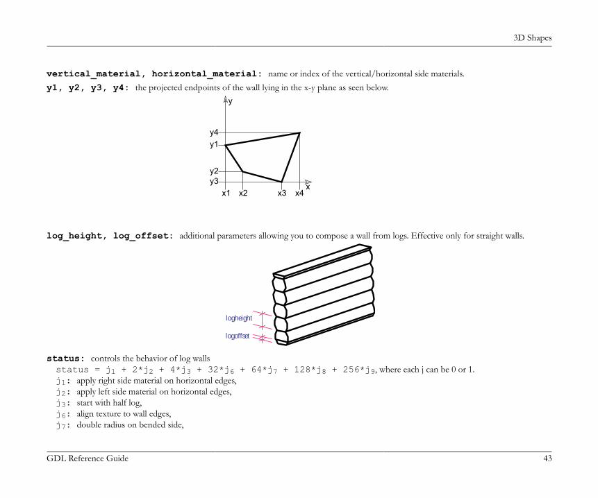
3D Shapes
GDL Reference Guide 43
vertical_material, horizontal_material: name or index of the vertical/horizontal side materials.y1, y2, y3, y4: the projected endpoints of the wall lying in the x-y plane as seen below.
x
y
x1 x2 x3 x4y3y2
y1y4
log_height, log_offset: additional parameters allowing you to compose a wall from logs. Effective only for straight walls.
logoffset
logheight
status: controls the behavior of log wallsstatus = j1 + 2*j2 + 4*j3 + 32*j6 + 64*j7 + 128*j8 + 256*j9, where each j can be 0 or 1.j1: apply right side material on horizontal edges,j2: apply left side material on horizontal edges,j3: start with half log,j6: align texture to wall edges,j7: double radius on bended side,
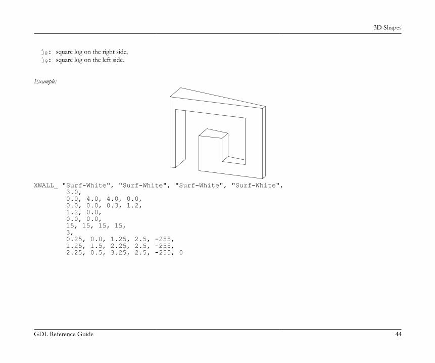
3D Shapes
GDL Reference Guide 44
j8: square log on the right side,j9: square log on the left side.
Example:
XWALL_ "Surf-White", "Surf-White", "Surf-White", "Surf-White", 3.0, 0.0, 4.0, 4.0, 0.0, 0.0, 0.0, 0.3, 1.2, 1.2, 0.0, 0.0, 0.0, 15, 15, 15, 15, 3, 0.25, 0.0, 1.25, 2.5, -255, 1.25, 1.5, 2.25, 2.5, -255, 2.25, 0.5, 3.25, 2.5, -255, 0
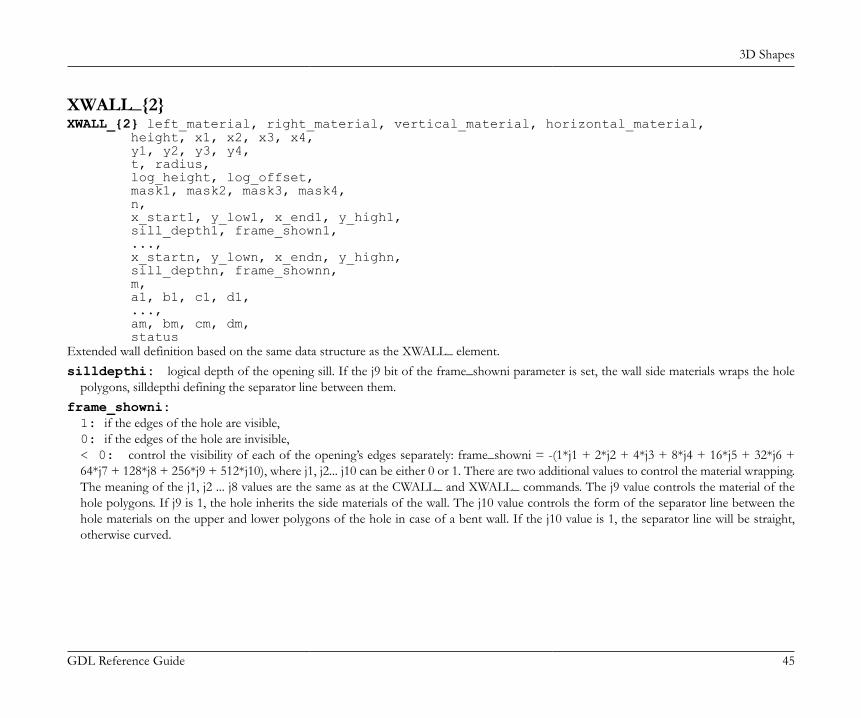
3D Shapes
GDL Reference Guide 45
XWALL_{2}XWALL_{2} left_material, right_material, vertical_material, horizontal_material, height, x1, x2, x3, x4, y1, y2, y3, y4, t, radius, log_height, log_offset, mask1, mask2, mask3, mask4, n, x_start1, y_low1, x_end1, y_high1, sill_depth1, frame_shown1, ..., x_startn, y_lown, x_endn, y_highn, sill_depthn, frame_shownn, m, a1, b1, c1, d1, ..., am, bm, cm, dm, statusExtended wall definition based on the same data structure as the XWALL_ element.silldepthi: logical depth of the opening sill. If the j9 bit of the frame_showni parameter is set, the wall side materials wraps the hole
polygons, silldepthi defining the separator line between them.frame_showni:1: if the edges of the hole are visible,0: if the edges of the hole are invisible,< 0: control the visibility of each of the opening’s edges separately: frame_showni = -(1*j1 + 2*j2 + 4*j3 + 8*j4 + 16*j5 + 32*j6 +64*j7 + 128*j8 + 256*j9 + 512*j10), where j1, j2... j10 can be either 0 or 1. There are two additional values to control the material wrapping.The meaning of the j1, j2 ... j8 values are the same as at the CWALL_ and XWALL_ commands. The j9 value controls the material of thehole polygons. If j9 is 1, the hole inherits the side materials of the wall. The j10 value controls the form of the separator line between thehole materials on the upper and lower polygons of the hole in case of a bent wall. If the j10 value is 1, the separator line will be straight,otherwise curved.
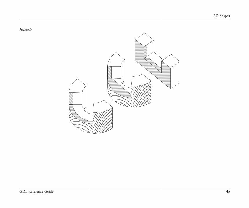
3D Shapes
GDL Reference Guide 46
Example:
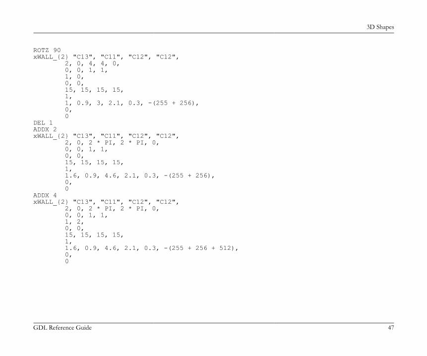
3D Shapes
GDL Reference Guide 47
ROTZ 90xWALL_{2} "C13", "C11", "C12", "C12", 2, 0, 4, 4, 0, 0, 0, 1, 1, 1, 0, 0, 0, 15, 15, 15, 15, 1, 1, 0.9, 3, 2.1, 0.3, -(255 + 256), 0, 0DEL 1ADDX 2xWALL_{2} "C13", "C11", "C12", "C12", 2, 0, 2 * PI, 2 * PI, 0, 0, 0, 1, 1, 0, 0, 15, 15, 15, 15, 1, 1.6, 0.9, 4.6, 2.1, 0.3, -(255 + 256), 0, 0ADDX 4xWALL_{2} "C13", "C11", "C12", "C12", 2, 0, 2 * PI, 2 * PI, 0, 0, 0, 1, 1, 1, 2, 0, 0, 15, 15, 15, 15, 1, 1.6, 0.9, 4.6, 2.1, 0.3, -(255 + 256 + 512), 0, 0
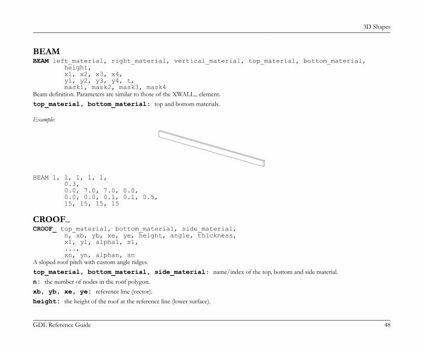
3D Shapes
GDL Reference Guide 48
BEAMBEAM left_material, right_material, vertical_material, top_material, bottom_material, height, x1, x2, x3, x4, y1, y2, y3, y4, t, mask1, mask2, mask3, mask4Beam definition. Parameters are similar to those of the XWALL_ element.top_material, bottom_material: top and bottom materials.
Example:
BEAM 1, 1, 1, 1, 1, 0.3, 0.0, 7.0, 7.0, 0.0, 0.0, 0.0, 0.1, 0.1, 0.5, 15, 15, 15, 15
CROOF_CROOF_ top_material, bottom_material, side_material, n, xb, yb, xe, ye, height, angle, thickness, x1, y1, alpha1, s1, ..., xn, yn, alphan, snA sloped roof pitch with custom angle ridges.top_material, bottom_material, side_material: name/index of the top, bottom and side material.n: the number of nodes in the roof polygon.xb, yb, xe, ye: reference line (vector).height: the height of the roof at the reference line (lower surface).

3D Shapes
GDL Reference Guide 49
angle: the rotation angle of the roof plane around the given oriented reference line in degrees (CCW).thickness: the thickness of the roof measured perpendicularly to the plane of the roof.xi, yi: the coordinates of the nodes of the roof ’s lower polygon.alphai: the angle between the face belonging to the edge i of the roof and the plane perpendicular to the roof plane, -90° < alphai <
90°. Looking in the direction of the edge of the properly oriented roof polygon, the CCW rotation angle is positive. The edges of the roofpolygon are oriented properly if, in top view, the contour is sequenced CCW and the holes are sequenced CW.
si: status code that allows you to control the visibility of polygon edges and side surfaces. You can also define holes and create segmentsand arcs in the polyline using special constraints.
x
y
z
heig
ht
alphai
angle(xe, ye)
(xb, yb)
See Status Codes for details.Restriction of parameters:n >= 3
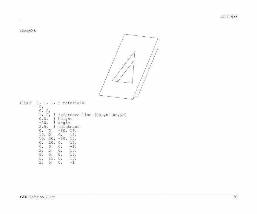
3D Shapes
GDL Reference Guide 50
Example 1:
CROOF_ 1, 1, 1, ! materials 9, 0, 0, 1, 0, ! reference line (xb,yb)(xe,ye) 0.0, ! height -30, ! angle 2.5, ! thickness 0, 0, -60, 15, 10, 0, 0, 15, 10, 20, -30, 15, 0, 20, 0, 15, 0, 0, 0, -1, 2, 5, 0, 15, 8, 5, 0, 15, 5, 15, 0, 15, 2, 5, 0, -1
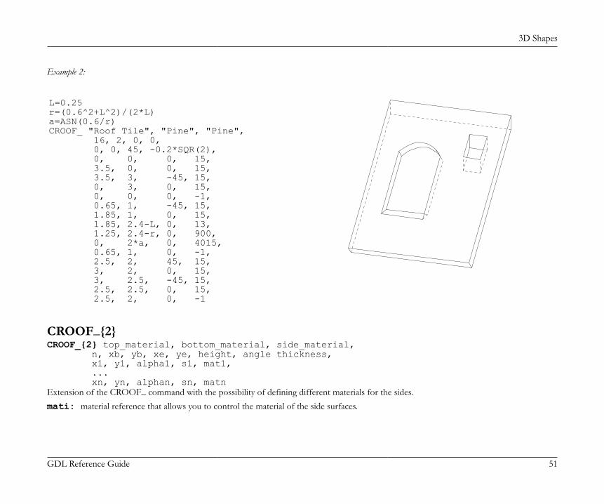
3D Shapes
GDL Reference Guide 51
Example 2:
L=0.25r=(0.6^2+L^2)/(2*L)a=ASN(0.6/r)CROOF_ "Roof Tile", "Pine", "Pine", 16, 2, 0, 0, 0, 0, 45, -0.2*SQR(2), 0, 0, 0, 15, 3.5, 0, 0, 15, 3.5, 3, -45, 15, 0, 3, 0, 15, 0, 0, 0, -1, 0.65, 1, -45, 15, 1.85, 1, 0, 15, 1.85, 2.4-L, 0, 13, 1.25, 2.4-r, 0, 900, 0, 2*a, 0, 4015, 0.65, 1, 0, -1, 2.5, 2, 45, 15, 3, 2, 0, 15, 3, 2.5, -45, 15, 2.5, 2.5, 0, 15, 2.5, 2, 0, -1
CROOF_{2}CROOF_{2} top_material, bottom_material, side_material, n, xb, yb, xe, ye, height, angle thickness, x1, y1, alpha1, s1, mat1, ... xn, yn, alphan, sn, matnExtension of the CROOF_ command with the possibility of defining different materials for the sides.mati: material reference that allows you to control the material of the side surfaces.
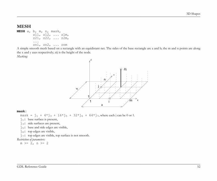
3D Shapes
GDL Reference Guide 52
MESHMESH a, b, m, n, mask, z11, z12, ... z1m, z21, z22, ... z2m, ... zn1, zn2, ... znmA simple smooth mesh based on a rectangle with an equidistant net. The sides of the base rectangle are a and b; the m and n points are alongthe x and y axes respectively; zij is the height of the node.Masking:
i
n
m1
Y
Zij
1
Z
X
jb
a
mask:mask = j1 + 4*j3 + 16*j5 + 32*j6 + 64*j7, where each j can be 0 or 1.j1: base surface is present,j3: side surfaces are present,j5: base and side edges are visible,j6: top edges are visible,j7: top edges are visible, top surface is not smooth.
Restriction of parameters:m >= 2, n >= 2
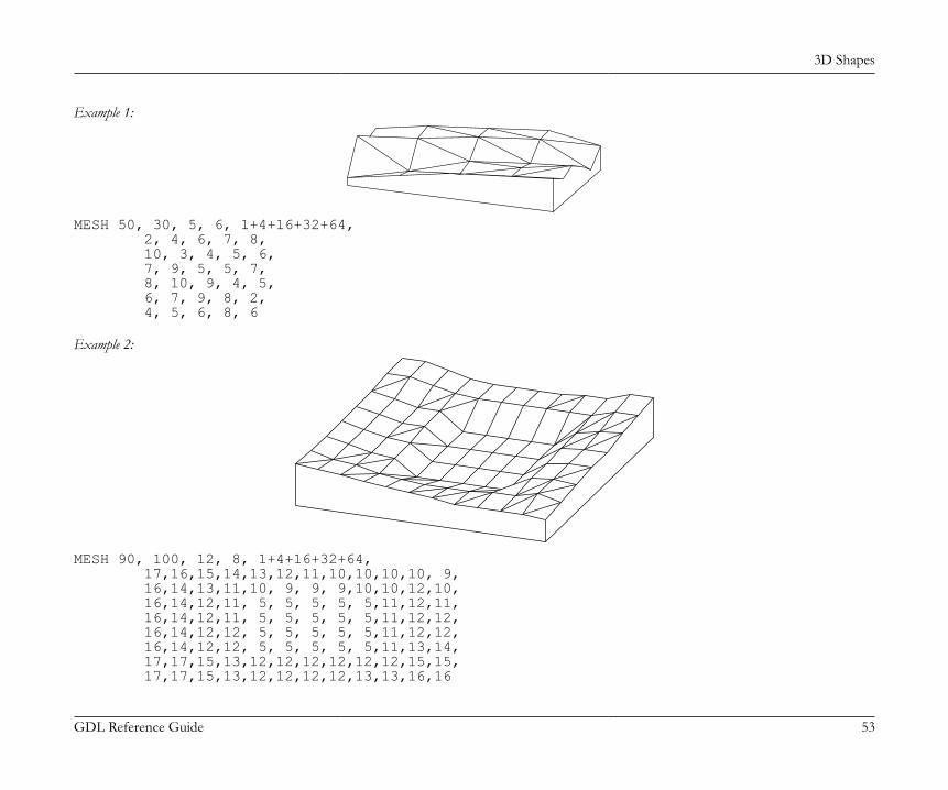
3D Shapes
GDL Reference Guide 53
Example 1:
MESH 50, 30, 5, 6, 1+4+16+32+64, 2, 4, 6, 7, 8, 10, 3, 4, 5, 6, 7, 9, 5, 5, 7, 8, 10, 9, 4, 5, 6, 7, 9, 8, 2, 4, 5, 6, 8, 6
Example 2:
MESH 90, 100, 12, 8, 1+4+16+32+64, 17,16,15,14,13,12,11,10,10,10,10, 9, 16,14,13,11,10, 9, 9, 9,10,10,12,10, 16,14,12,11, 5, 5, 5, 5, 5,11,12,11, 16,14,12,11, 5, 5, 5, 5, 5,11,12,12, 16,14,12,12, 5, 5, 5, 5, 5,11,12,12, 16,14,12,12, 5, 5, 5, 5, 5,11,13,14, 17,17,15,13,12,12,12,12,12,12,15,15, 17,17,15,13,12,12,12,12,13,13,16,16
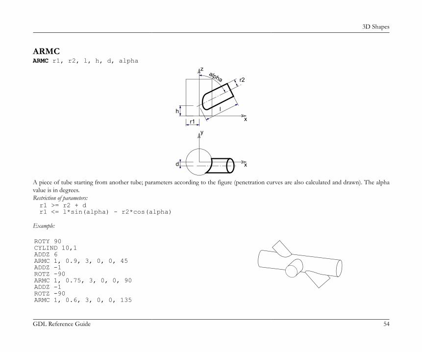
3D Shapes
GDL Reference Guide 54
ARMCARMC r1, r2, l, h, d, alpha
z
x
y
x
h
d
r2
r1
l
alpha
A piece of tube starting from another tube; parameters according to the figure (penetration curves are also calculated and drawn). The alphavalue is in degrees.Restriction of parameters:r1 >= r2 + dr1 <= l*sin(alpha) - r2*cos(alpha)
Example:
ROTY 90CYLIND 10,1ADDZ 6ARMC 1, 0.9, 3, 0, 0, 45ADDZ -1ROTZ -90ARMC 1, 0.75, 3, 0, 0, 90ADDZ -1ROTZ -90ARMC 1, 0.6, 3, 0, 0, 135
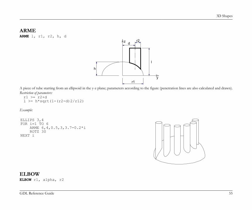
3D Shapes
GDL Reference Guide 55
ARMEARME l, r1, r2, h, d
y
z
h
dr2
r1
l
A piece of tube starting from an ellipsoid in the y-z plane; parameters according to the figure (penetration lines are also calculated and drawn).Restriction of parameters:r1 >= r2+dl >= h*sqrt(1-(r2-d)2/r12)
Example:
ELLIPS 3,4FOR i=1 TO 6 ARME 6,4,0.5,3,3.7-0.2*i ROTZ 30NEXT i
ELBOWELBOW r1, alpha, r2
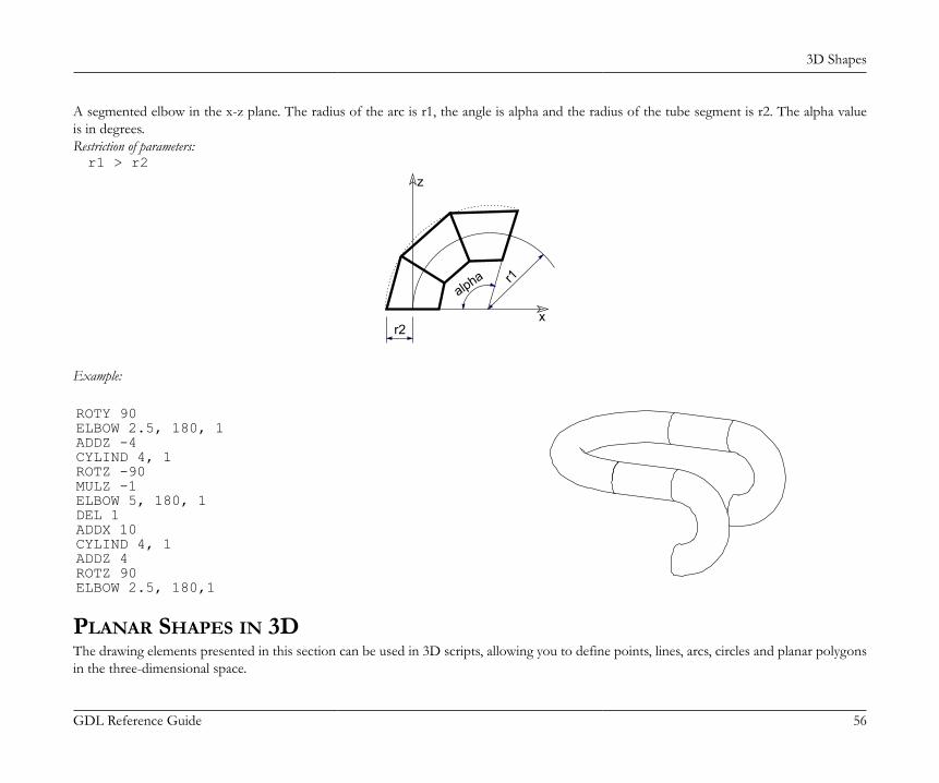
3D Shapes
GDL Reference Guide 56
A segmented elbow in the x-z plane. The radius of the arc is r1, the angle is alpha and the radius of the tube segment is r2. The alpha valueis in degrees.Restriction of parameters:r1 > r2
x
z
alpha r1
r2
Example:
ROTY 90ELBOW 2.5, 180, 1ADDZ -4CYLIND 4, 1ROTZ -90MULZ -1ELBOW 5, 180, 1DEL 1ADDX 10CYLIND 4, 1ADDZ 4ROTZ 90ELBOW 2.5, 180,1
PLANAR SHAPES IN 3DThe drawing elements presented in this section can be used in 3D scripts, allowing you to define points, lines, arcs, circles and planar polygonsin the three-dimensional space.
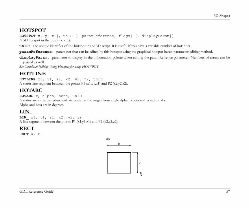
3D Shapes
GDL Reference Guide 57
HOTSPOTHOTSPOT x, y, z [, unID [, paramReference, flags] [, displayParam]]A 3D hotspot in the point (x, y, z).unID: the unique identifier of the hotspot in the 3D script. It is useful if you have a variable number of hotspots.paramReference: parameter that can be edited by this hotspot using the graphical hotspot based parameter editing method.displayParam: parameter to display in the information palette when editing the paramRefrence parameter. Members of arrays can be
passed as well.See Graphical Editing Using Hotspots for using HOTSPOT.
HOTLINEHOTLINE x1, y1, z1, x2, y2, z2, unIDA status line segment between the points P1 (x1,y1,z1) and P2 (x2,y2,z2).
HOTARCHOTARC r, alpha, beta, unIDA status arc in the x-y plane with its center at the origin from angle alpha to beta with a radius of r.Alpha and beta are in degrees.
LIN_LIN_ x1, y1, z1, x2, y2, z2A line segment between the points P1 (x1,y1,z1) and P2 (x2,y2,z2).
RECTRECT a, b
x
ya
b
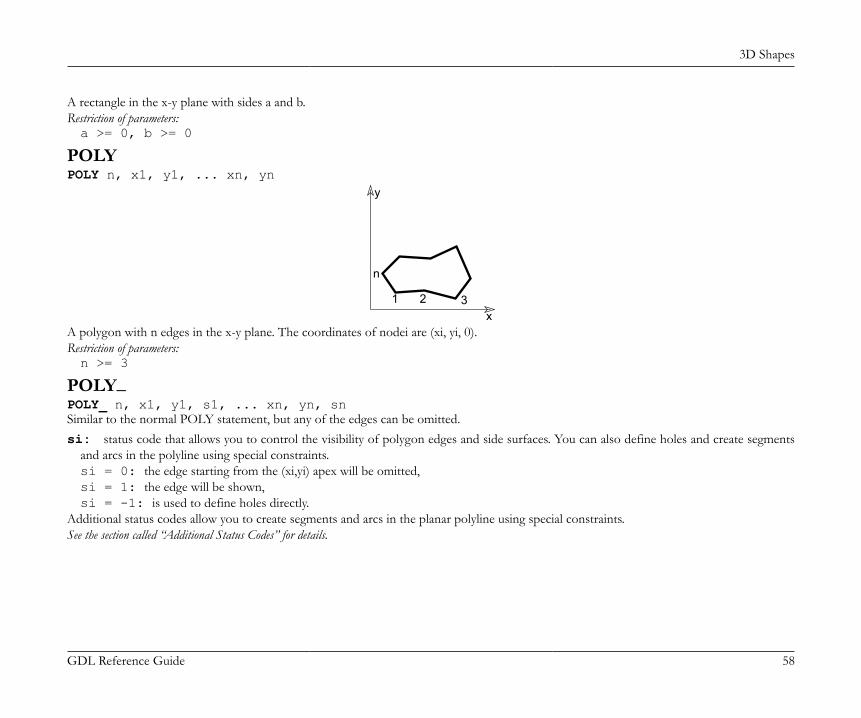
3D Shapes
GDL Reference Guide 58
A rectangle in the x-y plane with sides a and b.Restriction of parameters:a >= 0, b >= 0
POLYPOLY n, x1, y1, ... xn, yn
x
y
1 2 3
n
A polygon with n edges in the x-y plane. The coordinates of nodei are (xi, yi, 0).Restriction of parameters:n >= 3
POLY_POLY_ n, x1, y1, s1, ... xn, yn, snSimilar to the normal POLY statement, but any of the edges can be omitted.si: status code that allows you to control the visibility of polygon edges and side surfaces. You can also define holes and create segments
and arcs in the polyline using special constraints.si = 0: the edge starting from the (xi,yi) apex will be omitted,si = 1: the edge will be shown,si = -1: is used to define holes directly.
Additional status codes allow you to create segments and arcs in the planar polyline using special constraints.See the section called “Additional Status Codes” for details.
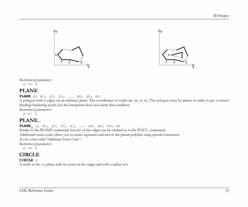
3D Shapes
GDL Reference Guide 59
x
y
1 2 3
n
x
y
1 2 3
n
Restriction of parameters:n >= 3
PLANEPLANE n, x1, y1, z1, ... xn, yn, znA polygon with n edges on an arbitrary plane. The coordinates of nodei are (xi, yi, zi). The polygon must be planar in order to get a correctshading/rendering result, but the interpreter does not check this condition.Restriction of parameters:n >= 3
PLANE_PLANE_ n, x1, y1, z1, s1, ... xn, yn, zn, snSimilar to the PLANE command, but any of the edges can be omitted as in the POLY_ command.Additional status codes allow you to create segments and arcs in the planar polyline using special constraints.See the section called “Additional Status Codes”.Restriction of parameters:n >= 3
CIRCLECIRCLE rA circle in the x-y plane with its center at the origin and with a radius of r.
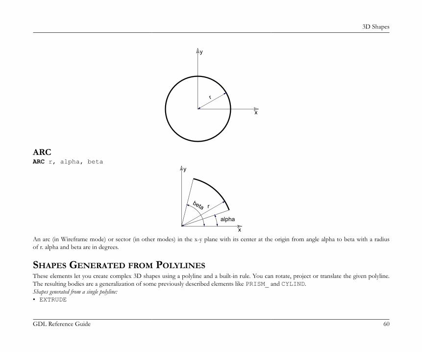
3D Shapes
GDL Reference Guide 60
x
y
r
ARCARC r, alpha, beta
x
y
r
alpha
beta
An arc (in Wireframe mode) or sector (in other modes) in the x-y plane with its center at the origin from angle alpha to beta with a radiusof r. alpha and beta are in degrees.
SHAPES GENERATED FROM POLYLINESThese elements let you create complex 3D shapes using a polyline and a built-in rule. You can rotate, project or translate the given polyline.The resulting bodies are a generalization of some previously described elements like PRISM_ and CYLIND.Shapes generated from a single polyline:• EXTRUDE
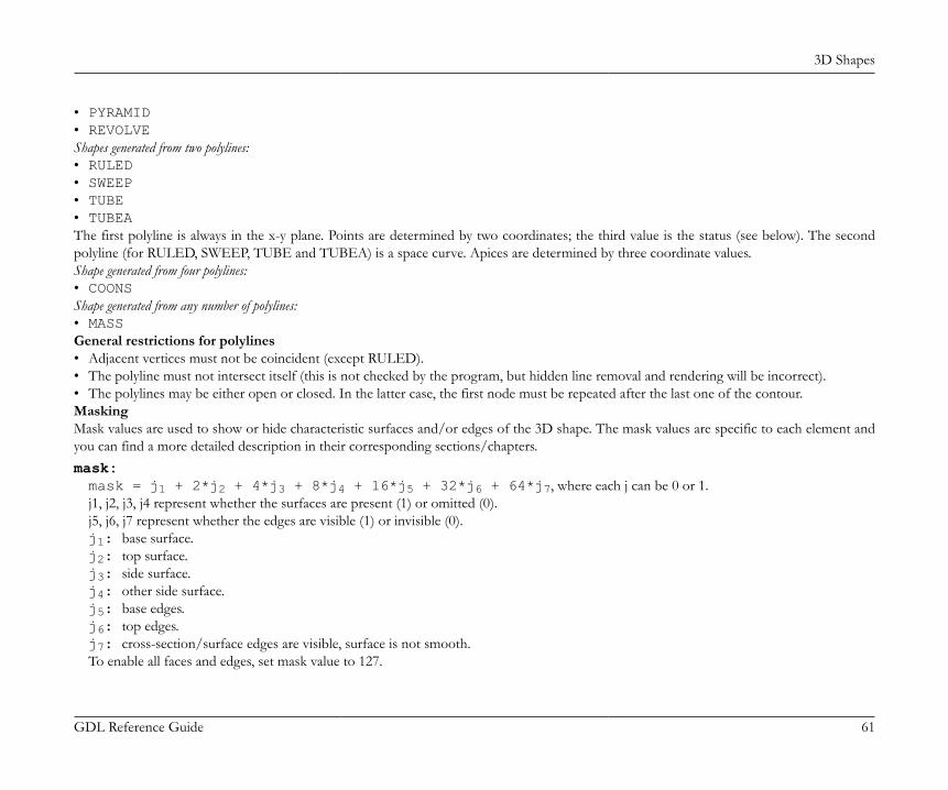
3D Shapes
GDL Reference Guide 61
• PYRAMID• REVOLVEShapes generated from two polylines:• RULED• SWEEP• TUBE• TUBEAThe first polyline is always in the x-y plane. Points are determined by two coordinates; the third value is the status (see below). The secondpolyline (for RULED, SWEEP, TUBE and TUBEA) is a space curve. Apices are determined by three coordinate values.Shape generated from four polylines:• COONSShape generated from any number of polylines:• MASSGeneral restrictions for polylines• Adjacent vertices must not be coincident (except RULED).• The polyline must not intersect itself (this is not checked by the program, but hidden line removal and rendering will be incorrect).• The polylines may be either open or closed. In the latter case, the first node must be repeated after the last one of the contour.MaskingMask values are used to show or hide characteristic surfaces and/or edges of the 3D shape. The mask values are specific to each element andyou can find a more detailed description in their corresponding sections/chapters.mask:mask = j1 + 2*j2 + 4*j3 + 8*j4 + 16*j5 + 32*j6 + 64*j7, where each j can be 0 or 1.j1, j2, j3, j4 represent whether the surfaces are present (1) or omitted (0).j5, j6, j7 represent whether the edges are visible (1) or invisible (0).j1: base surface.j2: top surface.j3: side surface.j4: other side surface.j5: base edges.j6: top edges.j7: cross-section/surface edges are visible, surface is not smooth.To enable all faces and edges, set mask value to 127.
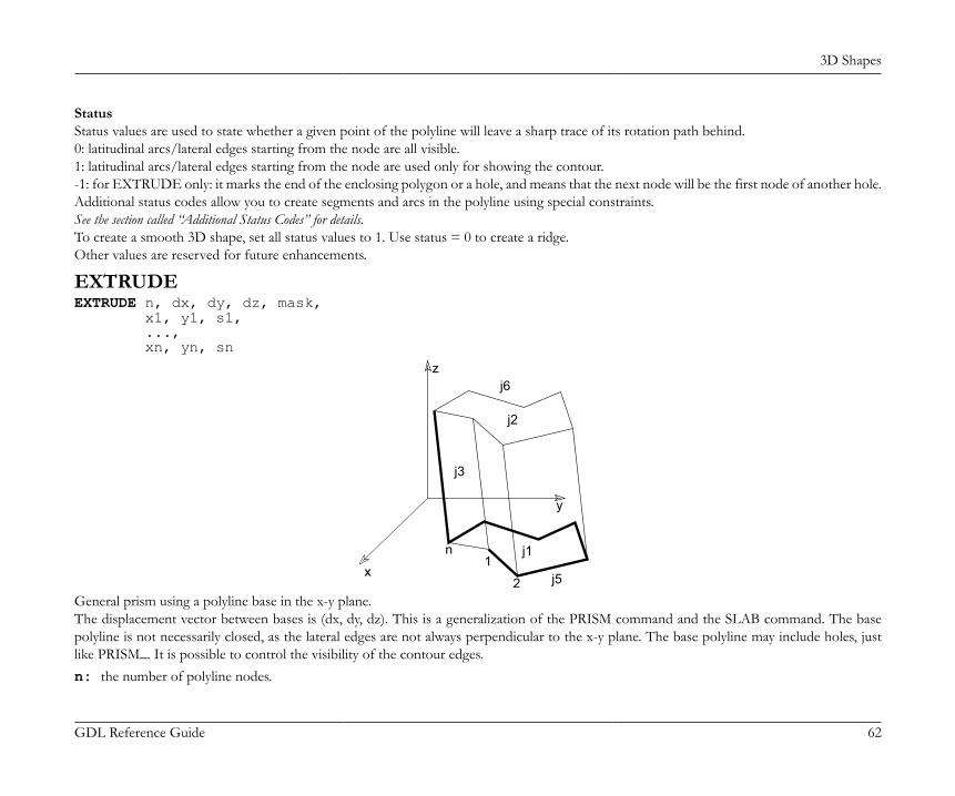
3D Shapes
GDL Reference Guide 62
StatusStatus values are used to state whether a given point of the polyline will leave a sharp trace of its rotation path behind.0: latitudinal arcs/lateral edges starting from the node are all visible.1: latitudinal arcs/lateral edges starting from the node are used only for showing the contour.-1: for EXTRUDE only: it marks the end of the enclosing polygon or a hole, and means that the next node will be the first node of another hole.Additional status codes allow you to create segments and arcs in the polyline using special constraints.See the section called “Additional Status Codes” for details.To create a smooth 3D shape, set all status values to 1. Use status = 0 to create a ridge.Other values are reserved for future enhancements.
EXTRUDEEXTRUDE n, dx, dy, dz, mask, x1, y1, s1, ..., xn, yn, sn
x
y
z
j1
j2
j3
j5
j6
1
2
n
General prism using a polyline base in the x-y plane.The displacement vector between bases is (dx, dy, dz). This is a generalization of the PRISM command and the SLAB command. The basepolyline is not necessarily closed, as the lateral edges are not always perpendicular to the x-y plane. The base polyline may include holes, justlike PRISM_. It is possible to control the visibility of the contour edges.n: the number of polyline nodes.
3D Shapes
GDL Reference Guide 63
mask: controls the existence of the bottom, top and (in case of an open polyline) side polygon.mask = j1 + 2*j2 + 4*j3 + 16*j5 + 32*j6 + 64*j7 + 128*j8, where each j can be 0 or 1.j1: base surface is present,j2: top surface is present,j3: side (closing) surface is present,j5: base edges are visible,j6: top edges are visible.j7: cross-section edges are visible, surface is articulated,j8: cross-section edges are sharp, the surface smoothing will stop here in OpenGL and rendering.
si: status of the lateral edges or marks the end of the polygon or of a hole. You can also define arcs and segments in the polyline usingadditional status code values:0: lateral edge starting from the node is visible,1: lateral edges starting from the node are used for showing the contour,-1: marks the end of the enclosing polygon or a hole, and means that the next node will be the first vertex of another hole.
Additional status codes allow you to create segments and arcs in the planar polyline using special constraints.See the section called “Additional Status Codes” for details.Restriction of parameters:n > 2
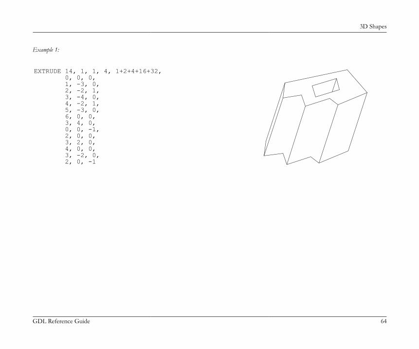
3D Shapes
GDL Reference Guide 64
Example 1:
EXTRUDE 14, 1, 1, 4, 1+2+4+16+32, 0, 0, 0, 1, -3, 0, 2, -2, 1, 3, -4, 0, 4, -2, 1, 5, -3, 0, 6, 0, 0, 3, 4, 0, 0, 0, -1, 2, 0, 0, 3, 2, 0, 4, 0, 0, 3, -2, 0, 2, 0, -1
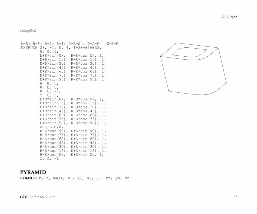
3D Shapes
GDL Reference Guide 65
Example 2:
A=5: B=5: R=2: S=1: C=R-S : D=A-R : E=B-REXTRUDE 28, -1, 0, 4, 1+2+4+16+32, 0, 0, 0, D+R*sin(0), R-R*cos(0), 1, D+R*sin(15), R-R*cos(15), 1, D+R*sin(30), R-R*cos(30), 1, D+R*sin(45), R-R*cos(45), 1, D+R*sin(60), R-R*cos(60), 1, D+R*sin(75), R-R*cos(75), 1, D+R*sin(90), R-R*cos(90), 1, A, B, 0, 0, B, 0, 0, 0, -1, C, C, 0, D+S*sin(0), R-S*cos(0), 1, D+S*sin(15), R-S*cos(15), 1, D+S*sin(30), R-S*cos(30), 1, D+S*sin(45), R-S*cos(45), 1, D+S*sin(60), R-S*cos(60), 1, D+S*sin(75), R-S*cos(75), 1, D+S*sin(90), R-S*cos(90), 1, A-C,B-C,0, R-S*cos(90), E+S*sin(90), 1, R-S*cos(75), E+S*sin(75), 1, R-S*cos(60), E+S*sin(60), 1, R-S*cos(45), E+S*sin(45), 1, R-S*cos(30), E+S*sin(30), 1, R-S*cos(15), E+S*sin(15), 1, R-S*cos(0), E+S*sin(0), 1, C, C, -1
PYRAMIDPYRAMID n, h, mask, x1, y1, s1, ... xn, yn, sn
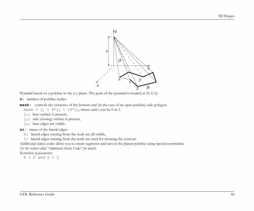
3D Shapes
GDL Reference Guide 66
x
y
z
j1
j3
j51
2
n
h
Pyramid based on a polyline in the x-y plane. The peak of the pyramid is located at (0, 0, h).n: number of polyline nodes.mask: controls the existence of the bottom and (in the case of an open polyline) side polygon.mask = j1 + 4*j3 + 16*j5, where each j can be 0 or 1.j1: base surface is present,j3: side (closing) surface is present,j5: base edges are visible.
si: status of the lateral edges.0: lateral edges starting from the node are all visible,1: lateral edges starting from the node are used for showing the contour.
Additional status codes allow you to create segments and arcs in the planar polyline using special constraints.See the section called “Additional Status Codes” for details.Restriction of parameters:h > 0 and n > 2
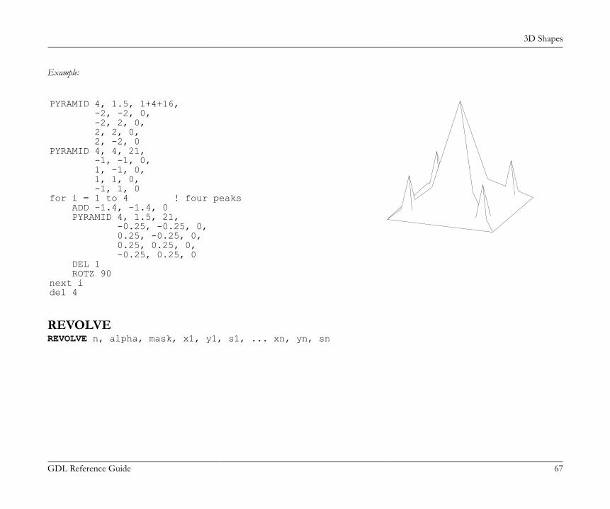
3D Shapes
GDL Reference Guide 67
Example:
PYRAMID 4, 1.5, 1+4+16, -2, -2, 0, -2, 2, 0, 2, 2, 0, 2, -2, 0PYRAMID 4, 4, 21, -1, -1, 0, 1, -1, 0, 1, 1, 0, -1, 1, 0for i = 1 to 4 ! four peaks ADD -1.4, -1.4, 0 PYRAMID 4, 1.5, 21, -0.25, -0.25, 0, 0.25, -0.25, 0, 0.25, 0.25, 0, -0.25, 0.25, 0 DEL 1 ROTZ 90next idel 4
REVOLVEREVOLVE n, alpha, mask, x1, y1, s1, ... xn, yn, sn
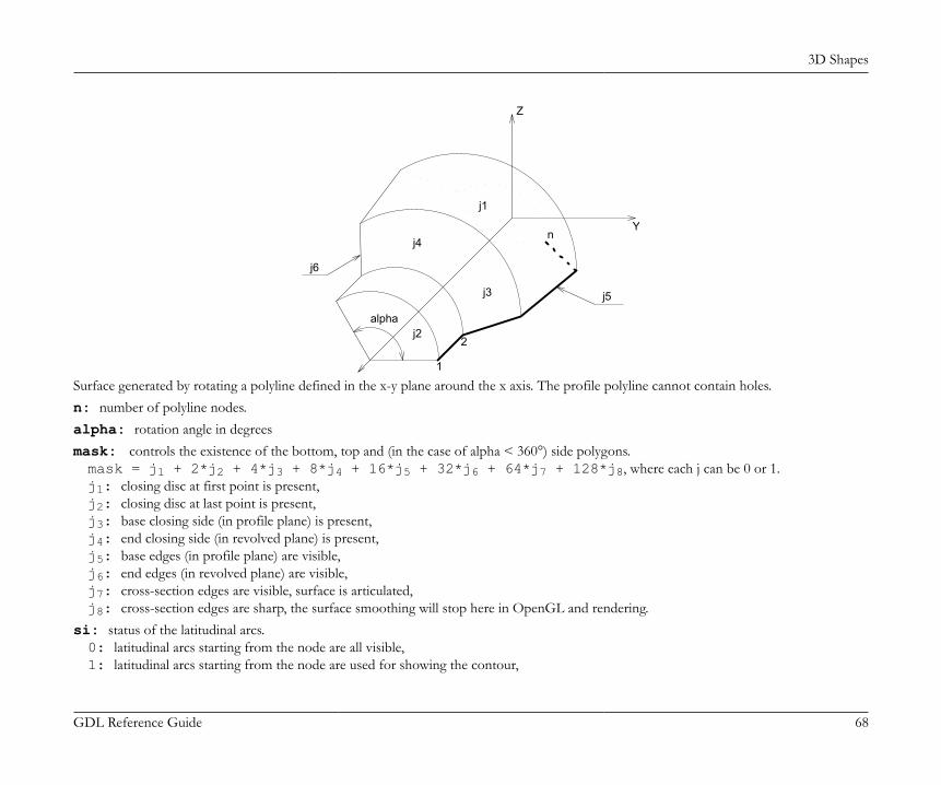
3D Shapes
GDL Reference Guide 68
j6
j1
j3
j2
j4
1
n
Z
2
Y
j5
alpha
Surface generated by rotating a polyline defined in the x-y plane around the x axis. The profile polyline cannot contain holes.n: number of polyline nodes.alpha: rotation angle in degreesmask: controls the existence of the bottom, top and (in the case of alpha < 360°) side polygons.mask = j1 + 2*j2 + 4*j3 + 8*j4 + 16*j5 + 32*j6 + 64*j7 + 128*j8, where each j can be 0 or 1.j1: closing disc at first point is present,j2: closing disc at last point is present,j3: base closing side (in profile plane) is present,j4: end closing side (in revolved plane) is present,j5: base edges (in profile plane) are visible,j6: end edges (in revolved plane) are visible,j7: cross-section edges are visible, surface is articulated,j8: cross-section edges are sharp, the surface smoothing will stop here in OpenGL and rendering.
si: status of the latitudinal arcs.0: latitudinal arcs starting from the node are all visible,1: latitudinal arcs starting from the node are used for showing the contour,
3D Shapes
GDL Reference Guide 69
2: when using ArchiCAD or Z-buffer Rendering Engine and setting Smooth Surfaces, the latitudinal edge belonging to this point definesa break. This solution is equivalent to the definition of additional nodes. The calculation is performed by the compiler. With other renderingmethods, it has the same effect as using 0.
Additional status codes allow you to create segments and arcs in the planar polyline using special constraints.See the section called “Additional Status Codes” for details.Restriction of parameters:n >= 2yi >= 0.0yi = 0.0 and yi+1 = 0.0 cannot stand at the same time(i.e., the y value of two neighboring nodes cannot be zero at the same time).
REVOLVE{2}REVOLVE{2} n, alphaOffset, alpha, mask, sideMat, x1, y1, s1, mat1, ... xn, yn, sn, matnAdvanced version of REVOLVE. The profile polygon will always be closed and may have holes. The start angle and the face materials arecontrollable.alphaOffset: rotation start angle.alpha: rotation angle length in degrees, may be negative.mask: controls the existence of the bottom, top and (in the case of alpha < 360°) side polygons.mask = 4*j3 + 8*j4 + 16*j5 + 32*j6 + 64*j7 + 128*j8, where each j can be 0 or 1.j3: base closing side (in profile plane) is present,j4: end closing side (in revolved plane) is present,j5: base edges (in profile plane) are visible,j6: end edges (in revolved plane) are visible,j7: cross-section edges are visible, surface is articulated,j8: cross-section edges are sharp, the surface smoothing will stop here in OpenGL and rendering.
sideMat: material of the closing faces.mati: material of the face generated from the i-th edge.
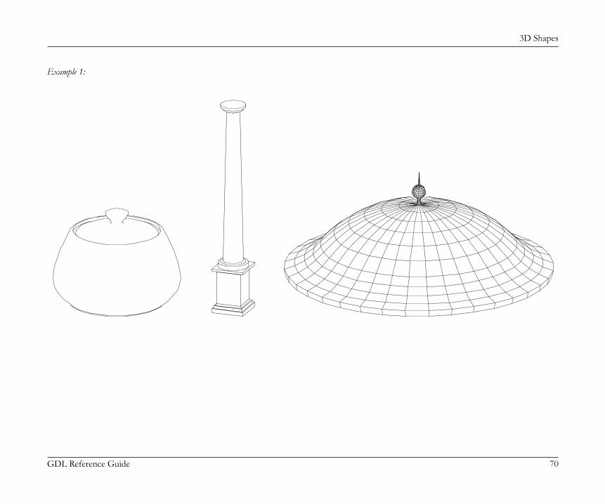
3D Shapes
GDL Reference Guide 70
Example 1:
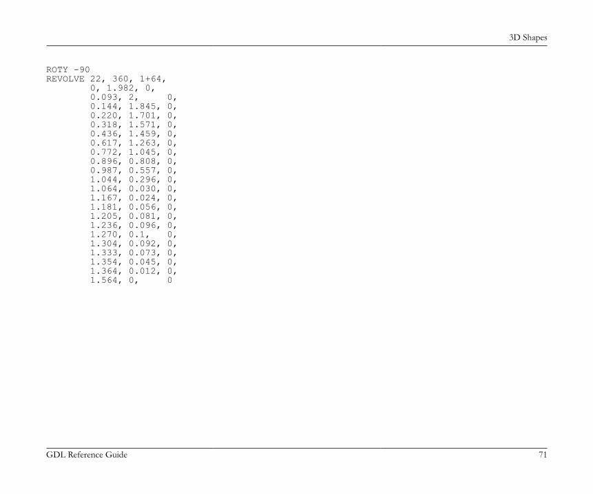
3D Shapes
GDL Reference Guide 71
ROTY -90REVOLVE 22, 360, 1+64, 0, 1.982, 0, 0.093, 2, 0, 0.144, 1.845, 0, 0.220, 1.701, 0, 0.318, 1.571, 0, 0.436, 1.459, 0, 0.617, 1.263, 0, 0.772, 1.045, 0, 0.896, 0.808, 0, 0.987, 0.557, 0, 1.044, 0.296, 0, 1.064, 0.030, 0, 1.167, 0.024, 0, 1.181, 0.056, 0, 1.205, 0.081, 0, 1.236, 0.096, 0, 1.270, 0.1, 0, 1.304, 0.092, 0, 1.333, 0.073, 0, 1.354, 0.045, 0, 1.364, 0.012, 0, 1.564, 0, 0

3D Shapes
GDL Reference Guide 72
Example 2:
3D Shapes
GDL Reference Guide 73
workaround without status code 2: the same result with status code 2:ROTY -90REVOLVE 26, 180, 16+32, 7, 1, 0, 6.0001, 1, 1, 6, 1, 0, 5.9999, 1.0002, 1, 5.5001, 1.9998, 1, 5.5, 2, 0, 5.4999, 1.9998, 1, 5.0001, 1.0002, 1, 5, 1, 0, 4.9999, 1, 1, 4.0001, 1, 1, 4, 1, 0, 3+cos(15), 1+sin(15), 1, 3+cos(30), 1+sin(30), 1, 3+cos(45), 1+sin(45), 1, 3+cos(60), 1+sin(60), 1, 3+cos(75), 1+sin(75), 1, 3, 2, 1, 3+cos(105), 1+sin(105), 1, 3+cos(120), 1+sin(120), 1, 3+cos(135), 1+sin(135), 1, 3+cos(150), 1+sin(150), 1, 3+cos(165), 1+sin(165), 1, 2, 1, 0, 1.9999, 1, 0, 1, 1, 0
ROTY -90REVOLVE 18, 180, 48, 7, 1, 0, 6, 1, 2, 5.5, 2, 2, 5, 1, 2, 4, 1, 2, 3+cos(15), 1+sin(15), 1, 3+cos(30), 1+sin(30), 1, 3+cos(45), 1+sin(45), 1, 3+cos(60), 1+sin(60), 1, 3+cos(75), 1+sin(75), 1, 3, 2, 1, 3+cos(105), 1+sin(105), 1, 3+cos(120), 1+sin(120), 1, 3+cos(135), 1+sin(135), 1, 3+cos(150), 1+sin(150), 1, 3+cos(165), 1+sin(165), 1, 2, 1, 2, 1, 1, 0
RULEDRULED n, mask, u1, v1, s1, ... un, vn, sn, x1, y1, z1, ... xn, yn, zn
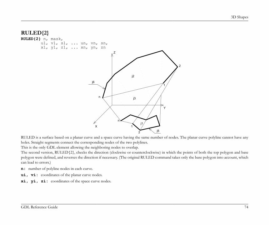
3D Shapes
GDL Reference Guide 74
RULED{2}RULED{2} n, mask, u1, v1, s1, ... un, vn, sn, x1, y1, z1, ... xn, yn, zn
j3
j61
n
j2
j51
Z
2
n
Xj1
Y
2
RULED is a surface based on a planar curve and a space curve having the same number of nodes. The planar curve polyline cannot have anyholes. Straight segments connect the corresponding nodes of the two polylines.This is the only GDL element allowing the neighboring nodes to overlap.The second version, RULED{2}, checks the direction (clockwise or counterclockwise) in which the points of both the top polygon and basepolygon were defined, and reverses the direction if necessary. (The original RULED command takes only the base polygon into account, whichcan lead to errors.)n: number of polyline nodes in each curve.ui, vi: coordinates of the planar curve nodes.xi, yi, zi: coordinates of the space curve nodes.
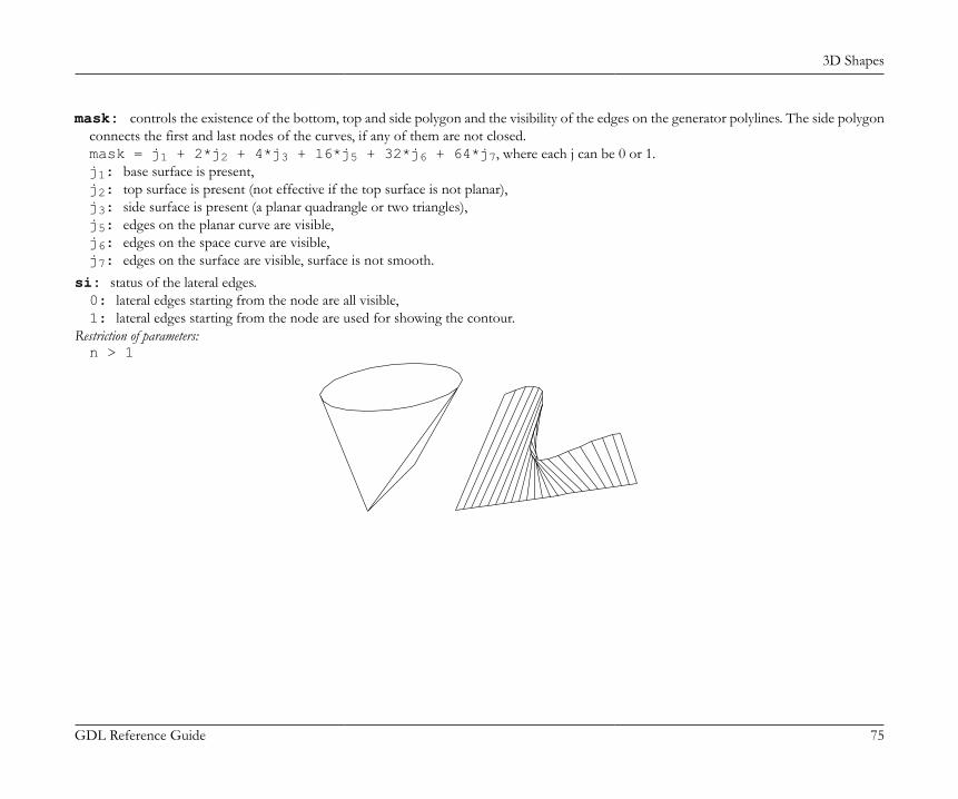
3D Shapes
GDL Reference Guide 75
mask: controls the existence of the bottom, top and side polygon and the visibility of the edges on the generator polylines. The side polygonconnects the first and last nodes of the curves, if any of them are not closed.mask = j1 + 2*j2 + 4*j3 + 16*j5 + 32*j6 + 64*j7, where each j can be 0 or 1.j1: base surface is present,j2: top surface is present (not effective if the top surface is not planar),j3: side surface is present (a planar quadrangle or two triangles),j5: edges on the planar curve are visible,j6: edges on the space curve are visible,j7: edges on the surface are visible, surface is not smooth.
si: status of the lateral edges.0: lateral edges starting from the node are all visible,1: lateral edges starting from the node are used for showing the contour.
Restriction of parameters:n > 1
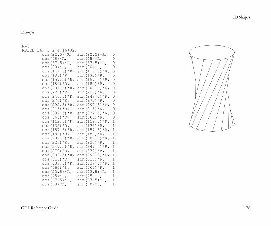
3D Shapes
GDL Reference Guide 76
Example:
R=3RULED 16, 1+2+4+16+32, cos(22.5)*R, sin(22.5)*R, 0, cos(45)*R, sin(45)*R, 0, cos(67.5)*R, sin(67.5)*R, 0, cos(90)*R, sin(90)*R, 0, cos(112.5)*R, sin(112.5)*R, 0, cos(135)*R, sin(135)*R, 0, cos(157.5)*R, sin(157.5)*R, 0, cos(180)*R, sin(180)*R, 0, cos(202.5)*R, sin(202.5)*R, 0, cos(225)*R, sin(225)*R, 0, cos(247.5)*R, sin(247.5)*R, 0, cos(270)*R, sin(270)*R, 0, cos(292.5)*R, sin(292.5)*R, 0, cos(315)*R, sin(315)*R, 0, cos(337.5)*R, sin(337.5)*R, 0, cos(360)*R, sin(360)*R, 0, cos(112.5)*R, sin(112.5)*R, 1, cos(135)*R, sin(135)*R, 1, cos(157.5)*R, sin(157.5)*R, 1, cos(180)*R, sin(180)*R, 1, cos(202.5)*R, sin(202.5)*R, 1, cos(225)*R, sin(225)*R, 1, cos(247.5)*R, sin(247.5)*R, 1, cos(270)*R, sin(270)*R, 1, cos(292.5)*R, sin(292.5)*R, 1, cos(315)*R, sin(315)*R, 1, cos(337.5)*R, sin(337.5)*R, 1, cos(360)*R, sin(360)*R, 1, cos(22.5)*R, sin(22.5)*R, 1, cos(45)*R, sin(45)*R, 1, cos(67.5)*R, sin(67.5)*R, 1, cos(90)*R, sin(90)*R, 1
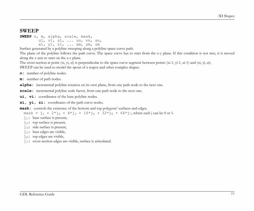
3D Shapes
GDL Reference Guide 77
SWEEPSWEEP n, m, alpha, scale, mask, u1, v1, s1, ... un, vn, sn, x1, y1, z1, ... xm, ym, zmSurface generated by a polyline sweeping along a polyline space curve path.The plane of the polyline follows the path curve. The space curve has to start from the x-y plane. If this condition is not met, it is movedalong the z axis to start on the x-y plane.The cross-section at point (xi, yi, zi) is perpendicular to the space curve segment between points (xi-1, yi-1, zi-1) and (xi, yi, zi).SWEEP can be used to model the spout of a teapot and other complex shapes.n: number of polyline nodes.m: number of path nodes.alpha: incremental polyline rotation on its own plane, from one path node to the next one.scale: incremental polyline scale factor, from one path node to the next one.ui, vi: coordinates of the base polyline nodes.xi, yi, zi: coordinates of the path curve nodes.mask: controls the existence of the bottom and top polygons’ surfaces and edges.mask = j1 + 2*j2 + 4*j3 + 16*j5 + 32*j6 + 64*j7, where each j can be 0 or 1.j1: base surface is present,j2: top surface is present,j3: side surface is present,j5: base edges are visible,j6: top edges are visible,j7: cross-section edges are visible, surface is articulated.
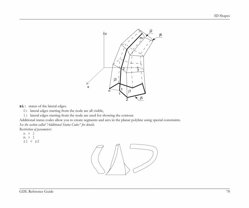
3D Shapes
GDL Reference Guide 78
x
y
z
1
2
n j1
j3
j5
j2j6
1
2
m
si: status of the lateral edges.0: lateral edges starting from the node are all visible,1: lateral edges starting from the node are used for showing the contour.
Additional status codes allow you to create segments and arcs in the planar polyline using special constraints.See the section called “Additional Status Codes” for details.Restriction of parameters:n > 1m > 1z1 < z2
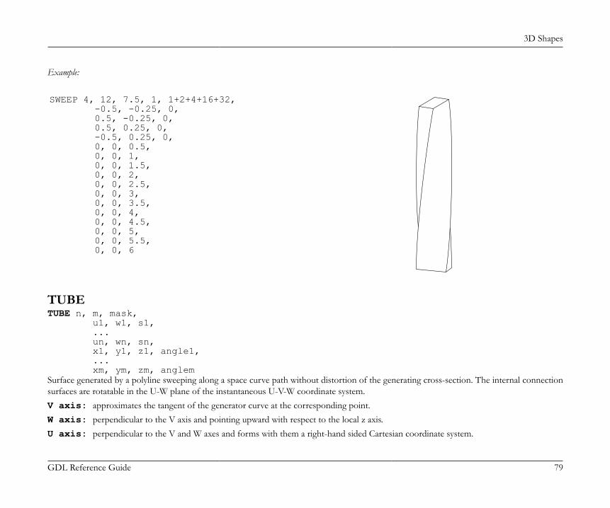
3D Shapes
GDL Reference Guide 79
Example:
SWEEP 4, 12, 7.5, 1, 1+2+4+16+32, -0.5, -0.25, 0, 0.5, -0.25, 0, 0.5, 0.25, 0, -0.5, 0.25, 0, 0, 0, 0.5, 0, 0, 1, 0, 0, 1.5, 0, 0, 2, 0, 0, 2.5, 0, 0, 3, 0, 0, 3.5, 0, 0, 4, 0, 0, 4.5, 0, 0, 5, 0, 0, 5.5, 0, 0, 6
TUBETUBE n, m, mask, u1, w1, s1, ... un, wn, sn, x1, y1, z1, angle1, ... xm, ym, zm, anglemSurface generated by a polyline sweeping along a space curve path without distortion of the generating cross-section. The internal connectionsurfaces are rotatable in the U-W plane of the instantaneous U-V-W coordinate system.V axis: approximates the tangent of the generator curve at the corresponding point.W axis: perpendicular to the V axis and pointing upward with respect to the local z axis.U axis: perpendicular to the V and W axes and forms with them a right-hand sided Cartesian coordinate system.
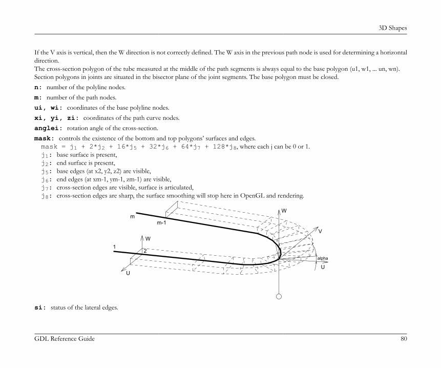
3D Shapes
GDL Reference Guide 80
If the V axis is vertical, then the W direction is not correctly defined. The W axis in the previous path node is used for determining a horizontaldirection.The cross-section polygon of the tube measured at the middle of the path segments is always equal to the base polygon (u1, w1, ... un, wn).Section polygons in joints are situated in the bisector plane of the joint segments. The base polygon must be closed.n: number of the polyline nodes.m: number of the path nodes.ui, wi: coordinates of the base polyline nodes.xi, yi, zi: coordinates of the path curve nodes.anglei: rotation angle of the cross-section.mask: controls the existence of the bottom and top polygons’ surfaces and edges.mask = j1 + 2*j2 + 16*j5 + 32*j6 + 64*j7 + 128*j8, where each j can be 0 or 1.j1: base surface is present,j2: end surface is present,j5: base edges (at x2, y2, z2) are visible,j6: end edges (at xm-1, ym-1, zm-1) are visible,j7: cross-section edges are visible, surface is articulated,j8: cross-section edges are sharp, the surface smoothing will stop here in OpenGL and rendering.
W
U
Wm
m-1
21
alpha
V
U
si: status of the lateral edges.
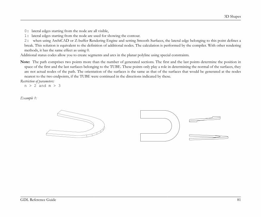
3D Shapes
GDL Reference Guide 81
0: lateral edges starting from the node are all visible,1: lateral edges starting from the node are used for showing the contour.2: when using ArchiCAD or Z-buffer Rendering Engine and setting Smooth Surfaces, the lateral edge belonging to this point defines abreak. This solution is equivalent to the definition of additional nodes. The calculation is performed by the compiler. With other renderingmethods, it has the same effect as using 0.
Additional status codes allow you to create segments and arcs in the planar polyline using special constraints.
Note: The path comprises two points more than the number of generated sections. The first and the last points determine the position inspace of the first and the last surfaces belonging to the TUBE. These points only play a role in determining the normal of the surfaces, theyare not actual nodes of the path. The orientation of the surfaces is the same as that of the surfaces that would be generated at the nodesnearest to the two endpoints, if the TUBE were continued in the directions indicated by these.
Restriction of parameters:n > 2 and m > 3
Example 1:
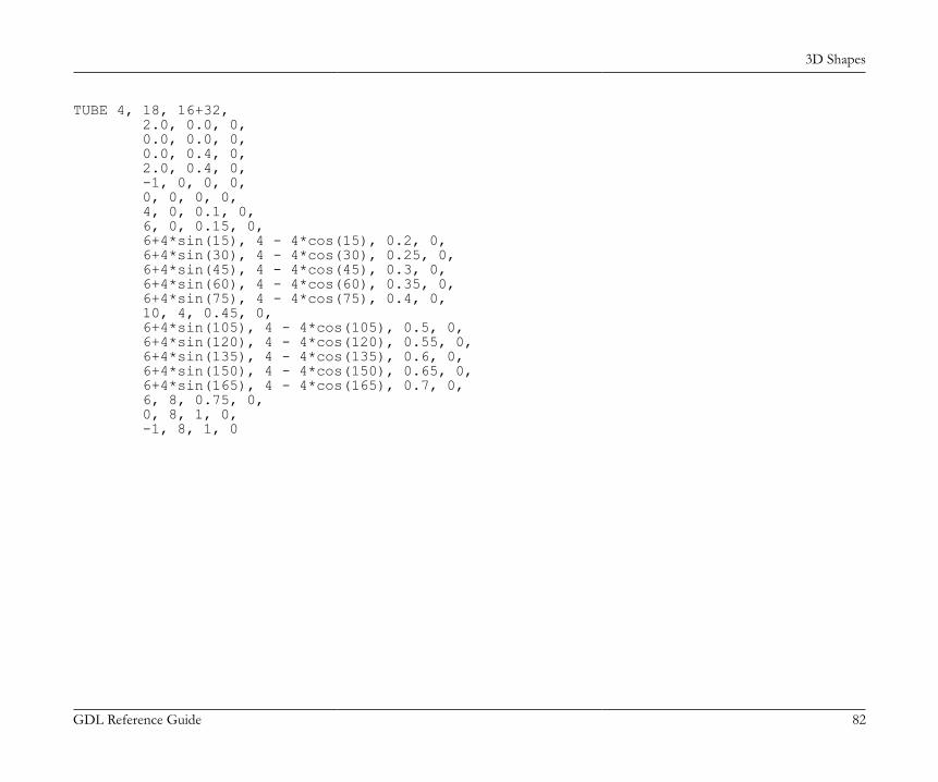
3D Shapes
GDL Reference Guide 82
TUBE 4, 18, 16+32, 2.0, 0.0, 0, 0.0, 0.0, 0, 0.0, 0.4, 0, 2.0, 0.4, 0, -1, 0, 0, 0, 0, 0, 0, 0, 4, 0, 0.1, 0, 6, 0, 0.15, 0, 6+4*sin(15), 4 - 4*cos(15), 0.2, 0, 6+4*sin(30), 4 - 4*cos(30), 0.25, 0, 6+4*sin(45), 4 - 4*cos(45), 0.3, 0, 6+4*sin(60), 4 - 4*cos(60), 0.35, 0, 6+4*sin(75), 4 - 4*cos(75), 0.4, 0, 10, 4, 0.45, 0, 6+4*sin(105), 4 - 4*cos(105), 0.5, 0, 6+4*sin(120), 4 - 4*cos(120), 0.55, 0, 6+4*sin(135), 4 - 4*cos(135), 0.6, 0, 6+4*sin(150), 4 - 4*cos(150), 0.65, 0, 6+4*sin(165), 4 - 4*cos(165), 0.7, 0, 6, 8, 0.75, 0, 0, 8, 1, 0, -1, 8, 1, 0
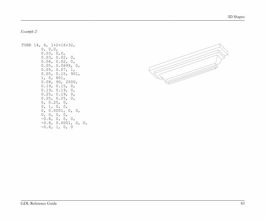
3D Shapes
GDL Reference Guide 83
Example 2:
TUBE 14, 6, 1+2+16+32, 0, 0,0, 0.03, 0,0, 0.03, 0.02, 0, 0.06, 0.02, 0, 0.05, 0.0699, 0, 0.05, 0.07, 1, 0.05, 0.15, 901, 1, 0, 801, 0.08, 90, 2000, 0.19, 0.15, 0, 0.19, 0.19, 0, 0.25, 0.19, 0, 0.25, 0.25, 0, 0, 0.25, 0, 0, 1, 0, 0, 0, 0.0001, 0, 0, 0, 0, 0, 0, -0.8, 0, 0, 0, -0.8, 0.0001, 0, 0, -0.8, 1, 0, 0
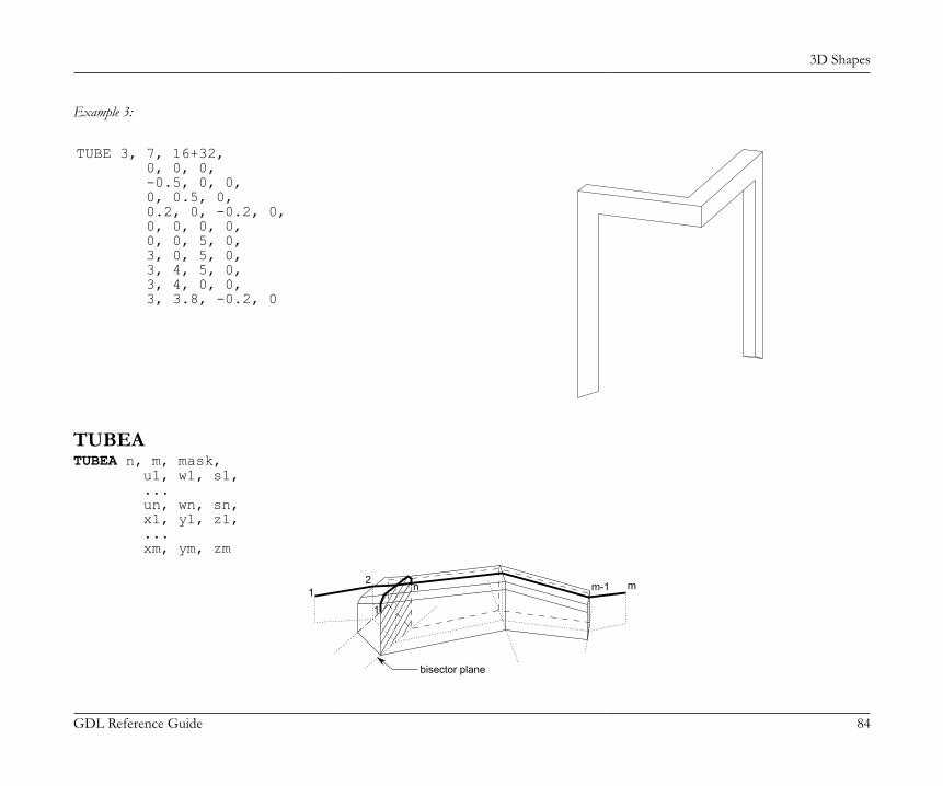
3D Shapes
GDL Reference Guide 84
Example 3:
TUBE 3, 7, 16+32, 0, 0, 0, -0.5, 0, 0, 0, 0.5, 0, 0.2, 0, -0.2, 0, 0, 0, 0, 0, 0, 0, 5, 0, 3, 0, 5, 0, 3, 4, 5, 0, 3, 4, 0, 0, 3, 3.8, -0.2, 0
TUBEATUBEA n, m, mask, u1, w1, s1, ... un, wn, sn, x1, y1, z1, ... xm, ym, zm
bisector plane
12
m-1 m
1
n
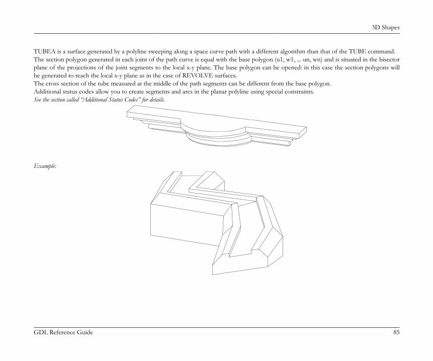
3D Shapes
GDL Reference Guide 85
TUBEA is a surface generated by a polyline sweeping along a space curve path with a different algorithm than that of the TUBE command.The section polygon generated in each joint of the path curve is equal with the base polygon (u1, w1, ... un, wn) and is situated in the bisectorplane of the projections of the joint segments to the local x-y plane. The base polygon can be opened: in this case the section polygons willbe generated to reach the local x-y plane as in the case of REVOLVE surfaces.The cross section of the tube measured at the middle of the path segments can be different from the base polygon.Additional status codes allow you to create segments and arcs in the planar polyline using special constraints.See the section called “Additional Status Codes” for details.
Example:
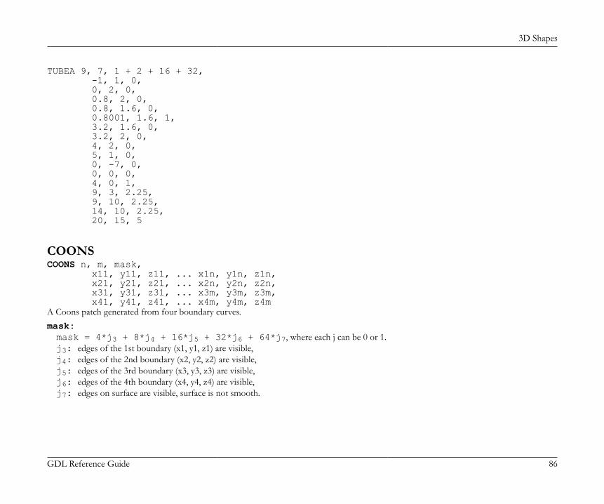
3D Shapes
GDL Reference Guide 86
TUBEA 9, 7, 1 + 2 + 16 + 32, -1, 1, 0, 0, 2, 0, 0.8, 2, 0, 0.8, 1.6, 0, 0.8001, 1.6, 1, 3.2, 1.6, 0, 3.2, 2, 0, 4, 2, 0, 5, 1, 0, 0, -7, 0, 0, 0, 0, 4, 0, 1, 9, 3, 2.25, 9, 10, 2.25, 14, 10, 2.25, 20, 15, 5
COONSCOONS n, m, mask, x11, y11, z11, ... x1n, y1n, z1n, x21, y21, z21, ... x2n, y2n, z2n, x31, y31, z31, ... x3m, y3m, z3m, x41, y41, z41, ... x4m, y4m, z4mA Coons patch generated from four boundary curves.mask:mask = 4*j3 + 8*j4 + 16*j5 + 32*j6 + 64*j7, where each j can be 0 or 1.j3: edges of the 1st boundary (x1, y1, z1) are visible,j4: edges of the 2nd boundary (x2, y2, z2) are visible,j5: edges of the 3rd boundary (x3, y3, z3) are visible,j6: edges of the 4th boundary (x4, y4, z4) are visible,j7: edges on surface are visible, surface is not smooth.
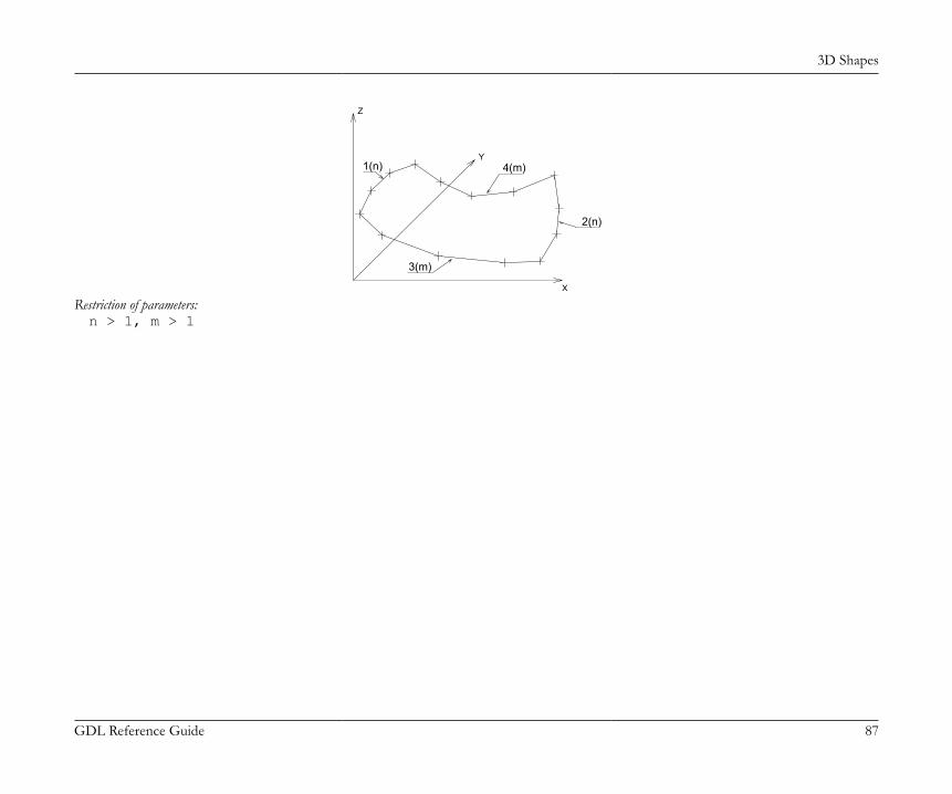
3D Shapes
GDL Reference Guide 87
4(m)
2(n)
3(m)
1(n)
Z
Y
X
Restriction of parameters:n > 1, m > 1
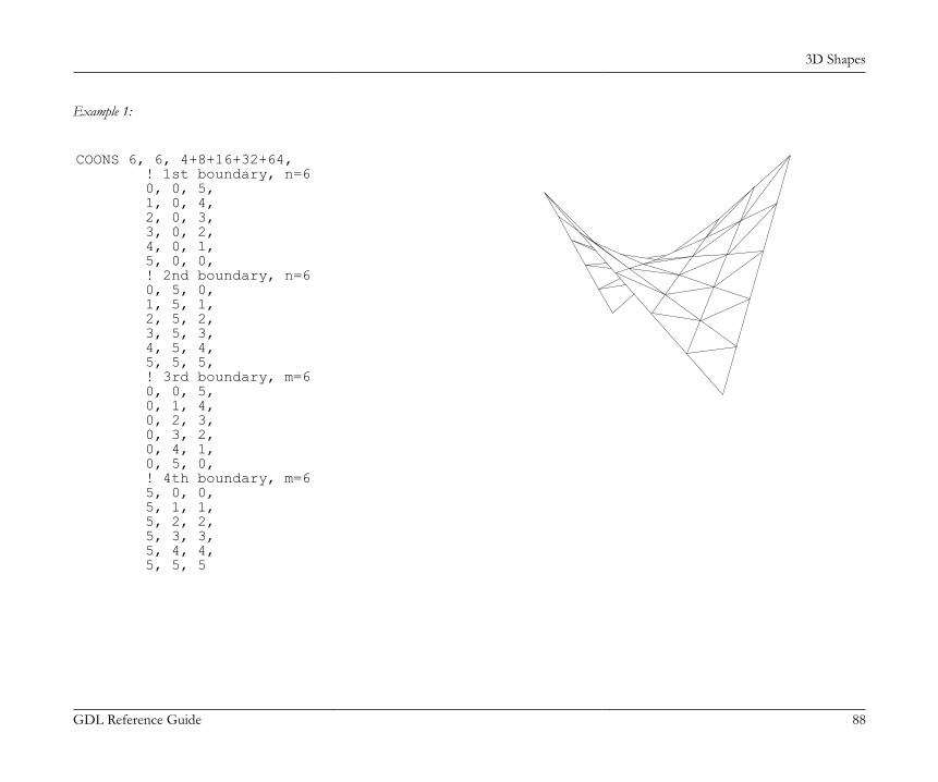
3D Shapes
GDL Reference Guide 88
Example 1:
COONS 6, 6, 4+8+16+32+64, ! 1st boundary, n=6 0, 0, 5, 1, 0, 4, 2, 0, 3, 3, 0, 2, 4, 0, 1, 5, 0, 0, ! 2nd boundary, n=6 0, 5, 0, 1, 5, 1, 2, 5, 2, 3, 5, 3, 4, 5, 4, 5, 5, 5, ! 3rd boundary, m=6 0, 0, 5, 0, 1, 4, 0, 2, 3, 0, 3, 2, 0, 4, 1, 0, 5, 0, ! 4th boundary, m=6 5, 0, 0, 5, 1, 1, 5, 2, 2, 5, 3, 3, 5, 4, 4, 5, 5, 5
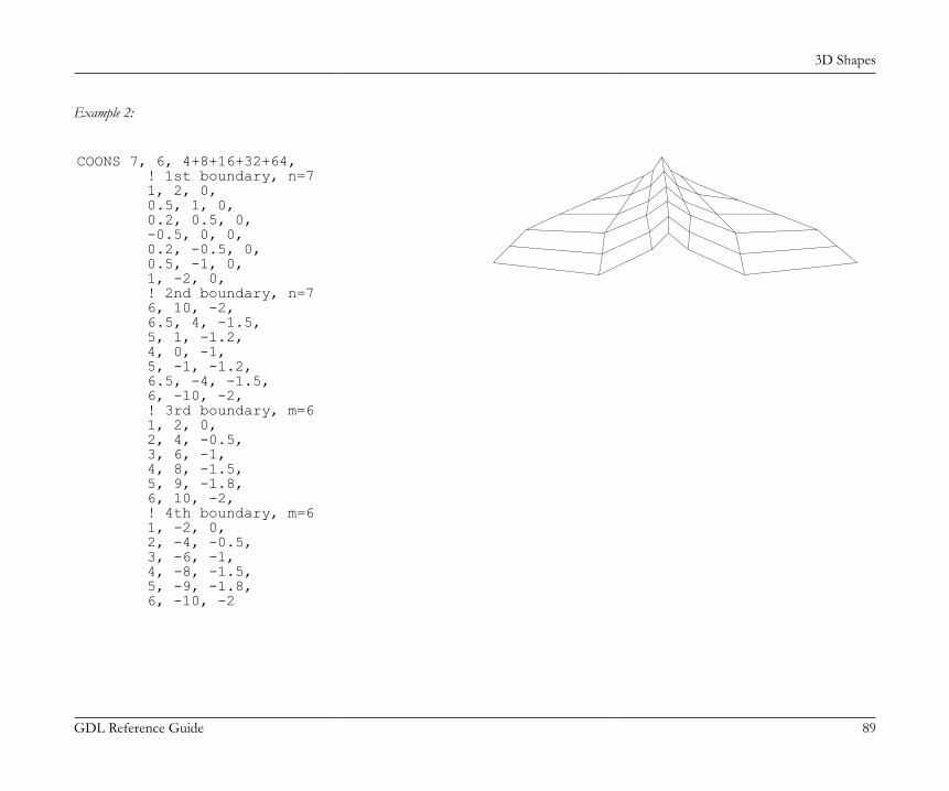
3D Shapes
GDL Reference Guide 89
Example 2:
COONS 7, 6, 4+8+16+32+64, ! 1st boundary, n=7 1, 2, 0, 0.5, 1, 0, 0.2, 0.5, 0, -0.5, 0, 0, 0.2, -0.5, 0, 0.5, -1, 0, 1, -2, 0, ! 2nd boundary, n=7 6, 10, -2, 6.5, 4, -1.5, 5, 1, -1.2, 4, 0, -1, 5, -1, -1.2, 6.5, -4, -1.5, 6, -10, -2, ! 3rd boundary, m=6 1, 2, 0, 2, 4, -0.5, 3, 6, -1, 4, 8, -1.5, 5, 9, -1.8, 6, 10, -2, ! 4th boundary, m=6 1, -2, 0, 2, -4, -0.5, 3, -6, -1, 4, -8, -1.5, 5, -9, -1.8, 6, -10, -2
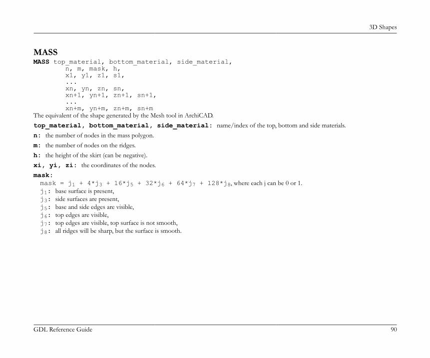
3D Shapes
GDL Reference Guide 90
MASSMASS top_material, bottom_material, side_material, n, m, mask, h, x1, y1, z1, s1, ... xn, yn, zn, sn, xn+1, yn+1, zn+1, sn+1, ... xn+m, yn+m, zn+m, sn+mThe equivalent of the shape generated by the Mesh tool in ArchiCAD.top_material, bottom_material, side_material: name/index of the top, bottom and side materials.n: the number of nodes in the mass polygon.m: the number of nodes on the ridges.h: the height of the skirt (can be negative).xi, yi, zi: the coordinates of the nodes.mask:mask = j1 + 4*j3 + 16*j5 + 32*j6 + 64*j7 + 128*j8, where each j can be 0 or 1.j1: base surface is present,j3: side surfaces are present,j5: base and side edges are visible,j6: top edges are visible,j7: top edges are visible, top surface is not smooth,j8: all ridges will be sharp, but the surface is smooth.
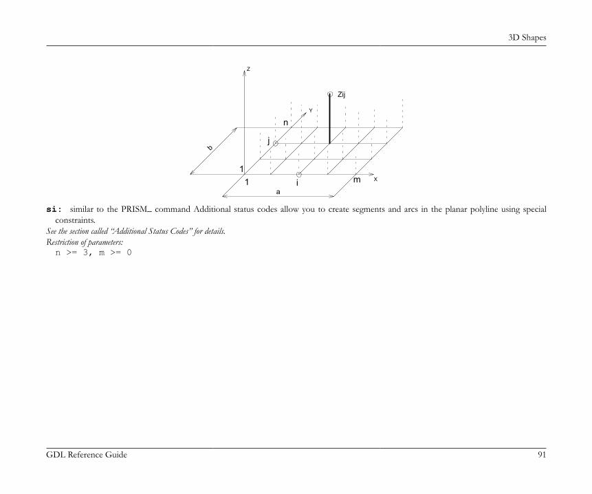
3D Shapes
GDL Reference Guide 91
i
n
m1
Y
Zij
1
Z
X
jb
a
si: similar to the PRISM_ command Additional status codes allow you to create segments and arcs in the planar polyline using specialconstraints.
See the section called “Additional Status Codes” for details.Restriction of parameters:n >= 3, m >= 0
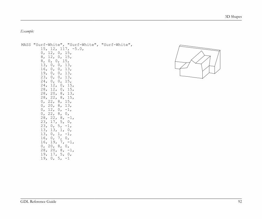
3D Shapes
GDL Reference Guide 92
Example:
MASS "Surf-White", "Surf-White", "Surf-White", 15, 12, 117, -5.0, 0, 12, 0, 15, 8, 12, 0, 15, 8, 0, 0, 15, 13, 0, 0, 13, 16, 0, 0, 13, 19, 0, 0, 13, 23, 0, 0, 13, 24, 0, 0, 15, 24, 12, 0, 15, 28, 12, 0, 15, 28, 20, 8, 13, 28, 22, 8, 15, 0, 22, 8, 15, 0, 20, 8, 13, 0, 12, 0, -1, 0, 22, 8, 0, 28, 22, 8, -1, 23, 17, 5, 0, 23, 0, 5, -1, 13, 13, 1, 0, 13, 0, 1, -1, 16, 0, 7, 0, 16, 19, 7, -1, 0, 20, 8, 0, 28, 20, 8, -1, 19, 17, 5, 0, 19, 0, 5, -1
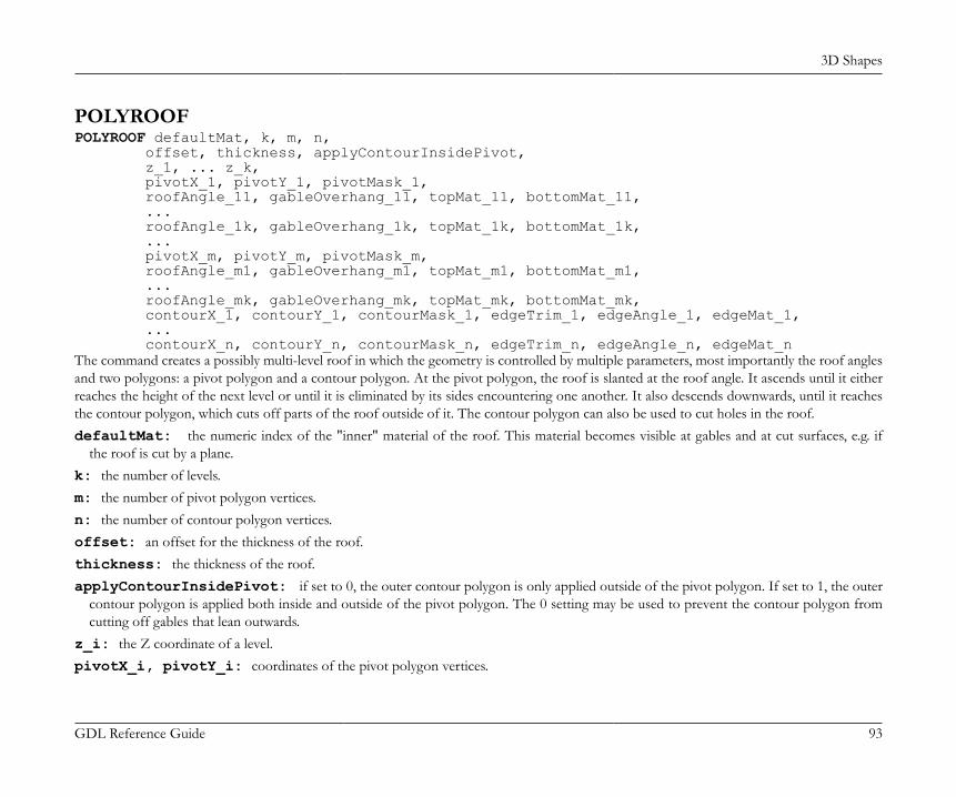
3D Shapes
GDL Reference Guide 93
POLYROOFPOLYROOF defaultMat, k, m, n, offset, thickness, applyContourInsidePivot, z_1, ... z_k, pivotX_1, pivotY_1, pivotMask_1, roofAngle_11, gableOverhang_11, topMat_11, bottomMat_11, ... roofAngle_1k, gableOverhang_1k, topMat_1k, bottomMat_1k, ... pivotX_m, pivotY_m, pivotMask_m, roofAngle_m1, gableOverhang_m1, topMat_m1, bottomMat_m1, ... roofAngle_mk, gableOverhang_mk, topMat_mk, bottomMat_mk, contourX_1, contourY_1, contourMask_1, edgeTrim_1, edgeAngle_1, edgeMat_1, ... contourX_n, contourY_n, contourMask_n, edgeTrim_n, edgeAngle_n, edgeMat_nThe command creates a possibly multi-level roof in which the geometry is controlled by multiple parameters, most importantly the roof anglesand two polygons: a pivot polygon and a contour polygon. At the pivot polygon, the roof is slanted at the roof angle. It ascends until it eitherreaches the height of the next level or until it is eliminated by its sides encountering one another. It also descends downwards, until it reachesthe contour polygon, which cuts off parts of the roof outside of it. The contour polygon can also be used to cut holes in the roof.defaultMat: the numeric index of the "inner" material of the roof. This material becomes visible at gables and at cut surfaces, e.g. if
the roof is cut by a plane.k: the number of levels.m: the number of pivot polygon vertices.n: the number of contour polygon vertices.offset: an offset for the thickness of the roof.thickness: the thickness of the roof.applyContourInsidePivot: if set to 0, the outer contour polygon is only applied outside of the pivot polygon. If set to 1, the outer
contour polygon is applied both inside and outside of the pivot polygon. The 0 setting may be used to prevent the contour polygon fromcutting off gables that lean outwards.
z_i: the Z coordinate of a level.pivotX_i, pivotY_i: coordinates of the pivot polygon vertices.
3D Shapes
GDL Reference Guide 94
pivotMask_i:0: marks a normal vertex,-1: marks the end of the current pivot subpolygon (outer contour or hole). Data for such a vertex must be a copy of the data for the firstvertex of the subpolygon. A polygon must always be closed with a mask value of -1, even if there are no holes inside it.
roofAngle_i: angle of slant for a pivot edge on a given level. If the angle >= 90, that part of the roof becomes a gable.gableOverhang_i: at the sides of a gable, the roof can extend over a lower level of itself. The amount of this can be controlled by this
parameter, which has effect only on gables (roofAngle >= 90) that are at least on the second level of the roof.topMat_i, bottomMat_i: the numeric index of the materials for the top and bottom of the roof.contourX_i, contourY_i: coordinates of the contour polygon vertices.contourMask_i:0: marks a normal vertex,-1: marks the end of the current contour subpolygon (outer contour or hole). Data for such a vertex must be a copy of the data for thefirst vertex of the subpolygon. A polygon must always be closed with a mask value of -1, even if there are no holes inside it.
edgeTrim_i: specifies the way the edge is trimmed by the contour polygon. Possible values are:0: Vertical,1: Perpendicular to roof plane,2: Horizontal,3: Custom angle to roof plane.
edgeAngle_i: the custom angle of the edge to the roof plane. It has effect only if edgeTrim is set to 3 (custom angle to roof plane).edgeMat_i: numeric index of the material at the edge the roof, where the contour cuts it
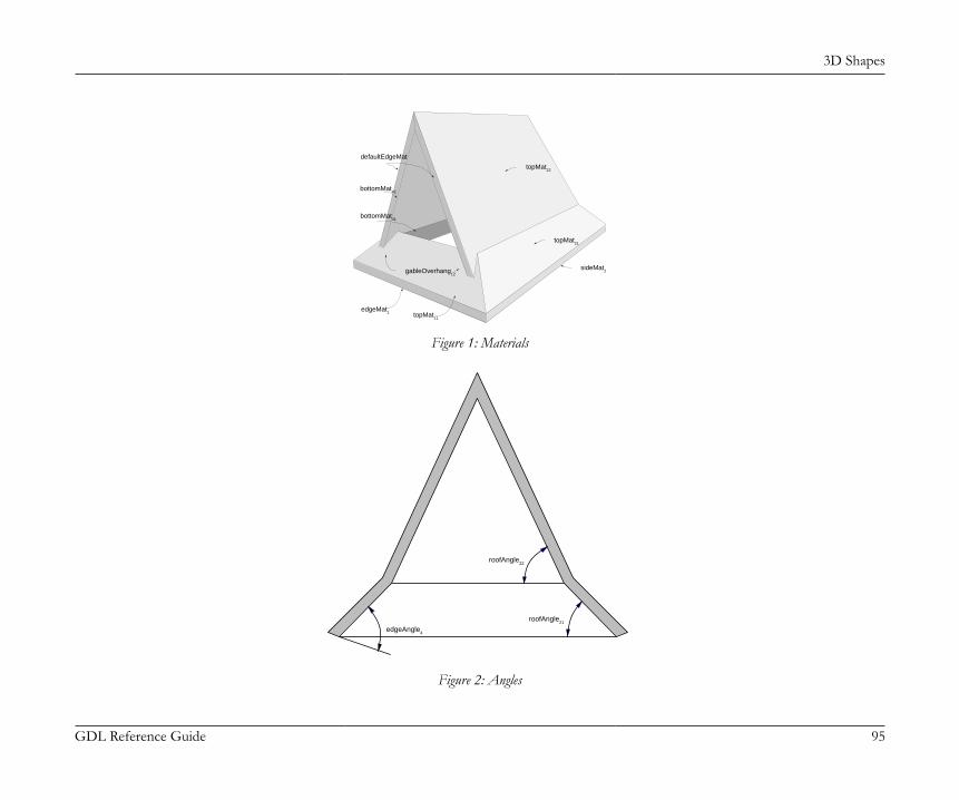
3D Shapes
GDL Reference Guide 95
defaultEdgeMat
bottomMat42
bottomMat41
topMat22
topMat21
sideMat2 gableOverhang
12
topMat11
edgeMat1
Figure 1: Materials
roofAngle22
roofAngle21
edgeAngle4
Figure 2: Angles
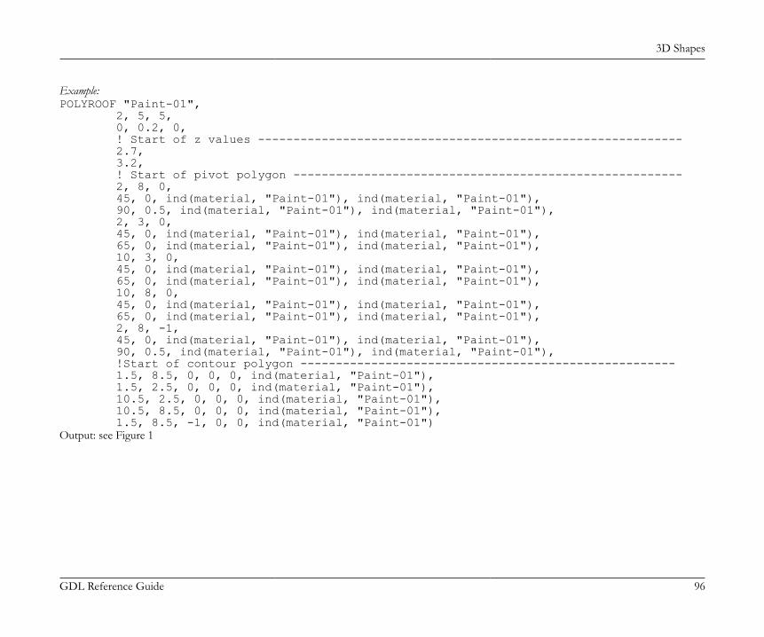
3D Shapes
GDL Reference Guide 96
Example:POLYROOF "Paint-01", 2, 5, 5, 0, 0.2, 0, ! Start of z values ------------------------------------------------------------ 2.7, 3.2, ! Start of pivot polygon ------------------------------------------------------- 2, 8, 0, 45, 0, ind(material, "Paint-01"), ind(material, "Paint-01"), 90, 0.5, ind(material, "Paint-01"), ind(material, "Paint-01"), 2, 3, 0, 45, 0, ind(material, "Paint-01"), ind(material, "Paint-01"), 65, 0, ind(material, "Paint-01"), ind(material, "Paint-01"), 10, 3, 0, 45, 0, ind(material, "Paint-01"), ind(material, "Paint-01"), 65, 0, ind(material, "Paint-01"), ind(material, "Paint-01"), 10, 8, 0, 45, 0, ind(material, "Paint-01"), ind(material, "Paint-01"), 65, 0, ind(material, "Paint-01"), ind(material, "Paint-01"), 2, 8, -1, 45, 0, ind(material, "Paint-01"), ind(material, "Paint-01"), 90, 0.5, ind(material, "Paint-01"), ind(material, "Paint-01"), !Start of contour polygon ----------------------------------------------------- 1.5, 8.5, 0, 0, 0, ind(material, "Paint-01"), 1.5, 2.5, 0, 0, 0, ind(material, "Paint-01"), 10.5, 2.5, 0, 0, 0, ind(material, "Paint-01"), 10.5, 8.5, 0, 0, 0, ind(material, "Paint-01"), 1.5, 8.5, -1, 0, 0, ind(material, "Paint-01")Output: see Figure 1
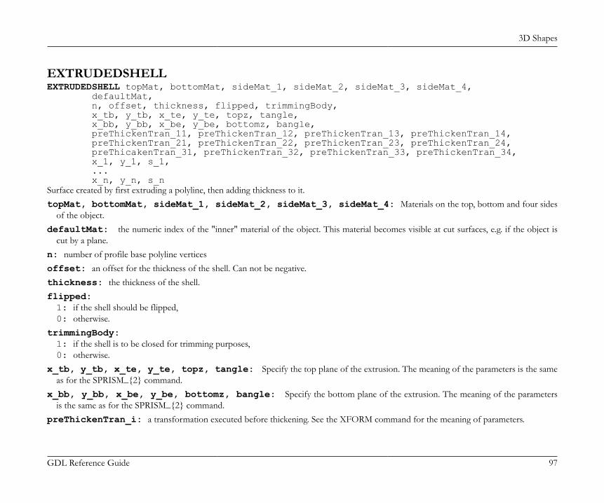
3D Shapes
GDL Reference Guide 97
EXTRUDEDSHELLEXTRUDEDSHELL topMat, bottomMat, sideMat_1, sideMat_2, sideMat_3, sideMat_4, defaultMat, n, offset, thickness, flipped, trimmingBody, x_tb, y_tb, x_te, y_te, topz, tangle, x_bb, y_bb, x_be, y_be, bottomz, bangle, preThickenTran_11, preThickenTran_12, preThickenTran_13, preThickenTran_14, preThickenTran_21, preThickenTran_22, preThickenTran_23, preThickenTran_24, preThicakenTran_31, preThickenTran_32, preThickenTran_33, preThickenTran_34, x_1, y_1, s_1, ... x_n, y_n, s_nSurface created by first extruding a polyline, then adding thickness to it.topMat, bottomMat, sideMat_1, sideMat_2, sideMat_3, sideMat_4: Materials on the top, bottom and four sides
of the object.defaultMat: the numeric index of the "inner" material of the object. This material becomes visible at cut surfaces, e.g. if the object is
cut by a plane.n: number of profile base polyline verticesoffset: an offset for the thickness of the shell. Can not be negative.thickness: the thickness of the shell.flipped:1: if the shell should be flipped,0: otherwise.
trimmingBody:1: if the shell is to be closed for trimming purposes,0: otherwise.
x_tb, y_tb, x_te, y_te, topz, tangle: Specify the top plane of the extrusion. The meaning of the parameters is the sameas for the SPRISM_{2} command.
x_bb, y_bb, x_be, y_be, bottomz, bangle: Specify the bottom plane of the extrusion. The meaning of the parametersis the same as for the SPRISM_{2} command.
preThickenTran_i: a transformation executed before thickening. See the XFORM command for the meaning of parameters.
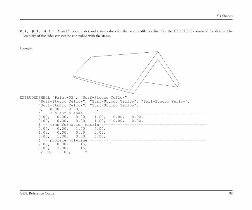
3D Shapes
GDL Reference Guide 98
x_i, y_i, s_i: X and Y coordinates and status values for the base profile polyline. See the EXTRUDE command for details. Thevisibility of the sides can not be controlled with the status.
Example:
EXTRUDEDSHELL "Paint-02", "Surf-Stucco Yellow", "Surf-Stucco Yellow", "Surf-Stucco Yellow", "Surf-Stucco Yellow", "Surf-Stucco Yellow", "Surf-Stucco Yellow", 3, 0.00, 0.30, 0, 0 ! -- 2 slant planes ---------------------------------------------------- 0.00, 0.00, 0.00, 1.00, 0.00, 0.00, 0.00, 0.00, 0.00, 1.00, -10.00, 0.00, ! -- transformation matrix --------------------------------------------- 0.00, 0.00, 1.00, 0.00, 1.00, 0.00, 0.00, 0.00, 0.00, 1.00, 0.00, 0.00, ! -- profile polyline -------------------------------------------------- 2.00, 0.00, 15, 0.00, 2.00, 15, -2.00, 0.00, 15
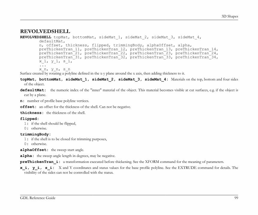
3D Shapes
GDL Reference Guide 99
REVOLVEDSHELLREVOLVEDSHELL topMat, bottomMat, sideMat_1, sideMat_2, sideMat_3, sideMat_4, defaultMat, n, offset, thickness, flipped, trimmingBody, alphaOffset, alpha, preThickenTran_11, preThickenTran_12, preThickenTran_13, preThickenTran_14, preThickenTran_21, preThickenTran_22, preThickenTran_23, preThickenTran_24, preThickenTran_31, preThickenTran_32, preThickenTran_33, preThickenTran_34, x_1, y_1, s_1, ... x_n, y_n, s_nSurface created by rotating a polyline defined in the x-y plane around the x axis, then adding thickness to it.topMat, bottomMat, sideMat_1, sideMat_2, sideMat_3, sideMat_4: Materials on the top, bottom and four sides
of the object.defaultMat: the numeric index of the "inner" material of the object. This material becomes visible at cut surfaces, e.g. if the object is
cut by a plane.n: number of profile base polyline vertices.offset: an offset for the thickness of the shell. Can not be negative.thickness: the thickness of the shell.flipped:1: if the shell should be flipped,0: otherwise.
trimmingBody:1: if the shell is to be closed for trimming purposes,0: otherwise.
alphaOffset: the sweep start angle.alpha: the sweep angle length in degrees, may be negative.preThickenTran_i: a transformation executed before thickening. See the XFORM command for the meaning of parameters.x_i, y_i, s_i: X and Y coordinates and status values for the base profile polyline. See the EXTRUDE command for details. The
visibility of the sides can not be controlled with the status.
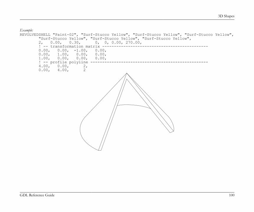
3D Shapes
GDL Reference Guide 100
Example:REVOLVEDSHELL "Paint-02", "Surf-Stucco Yellow", "Surf-Stucco Yellow", "Surf-Stucco Yellow", "Surf-Stucco Yellow", "Surf-Stucco Yellow", "Surf-Stucco Yellow", 2, 0.00, 0.30, 0, 0, 0.00, 270.00, ! -- transformation matrix --------------------------------------------- 0.00, 0.00, -1.00, 0.00, 0.00, 1.00, 0.00, 0.00, 1.00, 0.00, 0.00, 0.00, ! -- profile polyline -------------------------------------------------- 4.00, 0.00, 2, 0.00, 4.00, 2

3D Shapes
GDL Reference Guide 101
REVOLVEDSHELLANGULARREVOLVEDSHELLANGULAR topMat, bottomMat, sideMat_1, sideMat_2, sideMat_3, sideMat_4, defaultMat, n, offset, thickness, flipped, trimmingBody, alphaOffset, alpha, segmentationType, nOfSegments, preThickenTran_11, preThickenTran_12, preThickenTran_13, preThickenTran_14, preThickenTran_21, preThickenTran_22, preThickenTran_23, preThickenTran_24, preThickenTran_31, preThickenTran_32, preThickenTran_33, preThickenTran_34, x_1, y_1, s_1, ... x_n, y_n, s_nAn angular variant of the REVOLVEDSHELL command. Parameters are the same with the addition of the following extra parameters:segmentationType: Must be either 1 or 2.1: means that 360 degrees of revolution is split into nOfSegments segments,2: means that the actual revolution angle (given by the alpha parameter) is split into nOfSegments segments.
nOfSegments: Number of segments, see segmentationType parameter above.
3D Shapes
GDL Reference Guide 102
RULEDSHELLRULEDSHELL topMat, bottomMat, sideMat_1, sideMat_2, sideMat_3, sideMat_4, defaultMat, n, m, g, offset, thickness, flipped, trimmingBody, preThickenTran_11, preThickenTran_12, preThickenTran_13, preThickenTran_14, preThickenTran_21, preThickenTran_22, preThickenTran_23, preThickenTran_24, preThickenTran_31, preThickenTran_32, preThickenTran_33, preThickenTran_34, firstpolyX_1, firstpolyY_1, firstpolyS_1, ... firstpolyX_n, firstpolyY_n, firstpolyS_n, secondpolyX_1, secondpolyY_1, secondpolyS_1, ... secondpolyX_m, secondpolyY_m, secondpolyS_m, profile2Tran_11, profile2Tran_12, profile2Tran_13, profile2Tran_14 profile2Tran_21, profile2Tran_22, profile2Tran_23, profile2Tran_24 profile2Tran_31, profile2Tran_32, profile2Tran_33, profile2Tran 34 generatrixFirstIndex_1, generatrixSecondIndex_1, ... generatrixFirstIndex_g, generatrixSecondIndex_gSurface created by connecting two polylines.topMat, bottomMat, sideMat_1, sideMat_2, sideMat_3, sideMat_4: Materials on the top, bottom and four sides
of the object.defaultMat: the numeric index of the "inner" material of the object. This material becomes visible at cut surfaces, e.g. if the object is
cut by a plane.n: number of vertices for first profile base polyline.m: number of vertices for second profile base polyline.g: number of generatrices.offset: an offset for the thickness of the shell. Can not be negative.thickness: thickness of the shell.flipped:1: if the shell should be flipped,0: otherwise
preThickenTran: a transformation executed before thickening. See the XFORM command for the meaning of parameters.
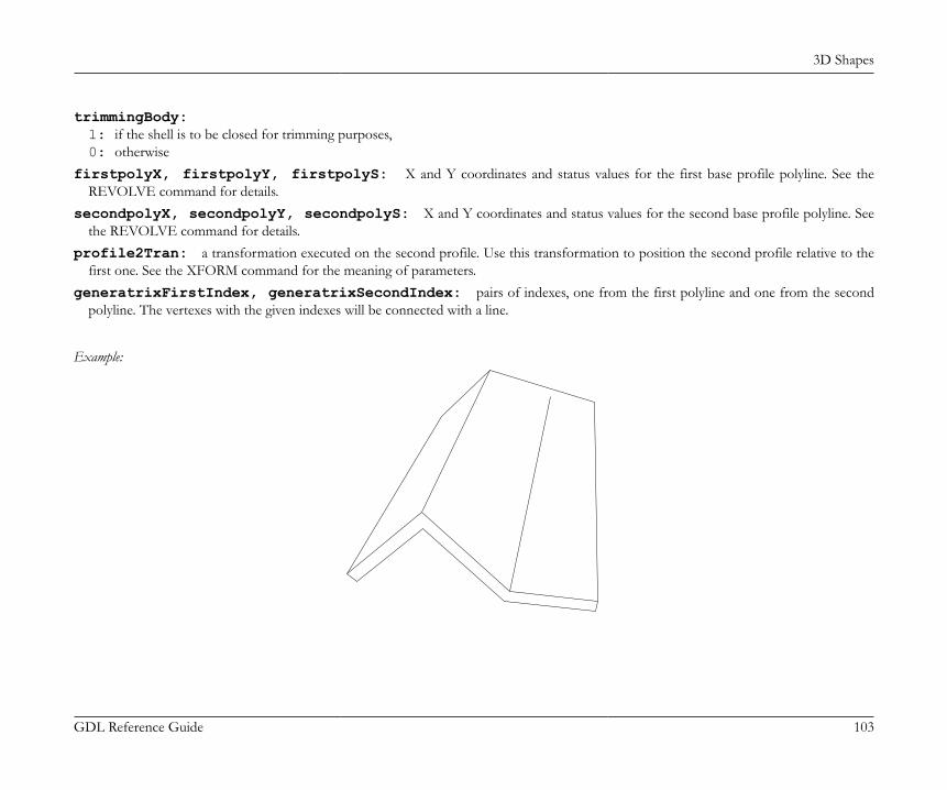
3D Shapes
GDL Reference Guide 103
trimmingBody:1: if the shell is to be closed for trimming purposes,0: otherwise
firstpolyX, firstpolyY, firstpolyS: X and Y coordinates and status values for the first base profile polyline. See theREVOLVE command for details.
secondpolyX, secondpolyY, secondpolyS: X and Y coordinates and status values for the second base profile polyline. Seethe REVOLVE command for details.
profile2Tran: a transformation executed on the second profile. Use this transformation to position the second profile relative to thefirst one. See the XFORM command for the meaning of parameters.
generatrixFirstIndex, generatrixSecondIndex: pairs of indexes, one from the first polyline and one from the secondpolyline. The vertexes with the given indexes will be connected with a line.
Example:
3D Shapes
GDL Reference Guide 104
RULEDSHELL "Paint-14", "Paint-14", "Paint-14", "Paint-14", "Paint-14", "Paint-14", "Paint-14", 4, 3, 3, 0.00, 0.30, 0, 0, ! -- transformation matrix --------------------------------------------- 1.00, 0.00, 0.00, 0.00, 0.00, 0.00, -1.00, 0.00, 0.00, 1.00, 0.00, 0.00, ! -- profile 1 polyline ------------------------------------------------ 0.00, 0.00, 2, 2.00, 2.00, 2, 4.00, 0.00, 2, 6.00, 0.00, 2, ! -- profile 2 polyline ------------------------------------------------ 0.00, 0.00, 2, 2.00, 2.00, 2, 6.00, 1.00, 2, ! -- transformation matrix --------------------------------------------- 1.00, 0.00, 0.00, 0.00, 0.00, 1.00, 0.00, 0.00, 0.00, 0.00, 1.00, -10.00, ! -- generatrices ------------------------------------------------------ 1, 1, 2, 2, 4, 3
ELEMENTS FOR VISUALIZATION
LIGHTLIGHT red, green, blue, shadow, radius, alpha, beta, angle_falloff, distance1, distance2, distance_falloff [[,] ADDITIONAL_DATA name1 = value1, name2 = value2, ...]A light source radiates [red, green, blue] colored light from the local origin along the local x axis. The light is projected parallel to the x axisfrom a point or circle source. It has its maximum intensity within the alpha-angle frustum of a cone and falls to zero at the beta-angle frustumof a cone. This falloff is controlled by the angle_falloff parameter. (Zero gives the light a sharp edge, higher values mean that the transition
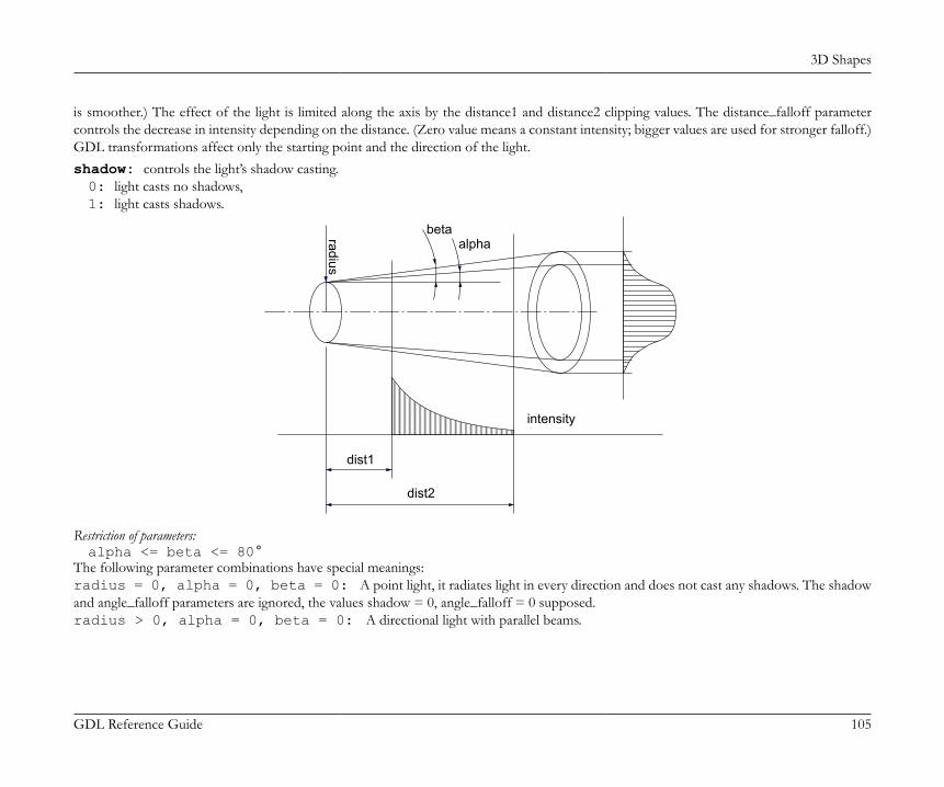
3D Shapes
GDL Reference Guide 105
is smoother.) The effect of the light is limited along the axis by the distance1 and distance2 clipping values. The distance_falloff parametercontrols the decrease in intensity depending on the distance. (Zero value means a constant intensity; bigger values are used for stronger falloff.)GDL transformations affect only the starting point and the direction of the light.shadow: controls the light’s shadow casting.0: light casts no shadows,1: light casts shadows.
betaalpha
intensity
dist1
dist2
radius
Restriction of parameters:alpha <= beta <= 80°
The following parameter combinations have special meanings:radius = 0, alpha = 0, beta = 0: A point light, it radiates light in every direction and does not cast any shadows. The shadowand angle_falloff parameters are ignored, the values shadow = 0, angle_falloff = 0 supposed.radius > 0, alpha = 0, beta = 0: A directional light with parallel beams.
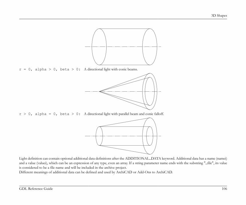
3D Shapes
GDL Reference Guide 106
r = 0, alpha > 0, beta > 0: A directional light with conic beams.
r > 0, alpha = 0, beta > 0: A directional light with parallel beam and conic falloff.
Light definition can contain optional additional data definitions after the ADDITIONAL_DATA keyword. Additional data has a name (namei)and a value (valuei), which can be an expression of any type, even an array. If a string parameter name ends with the substring "_file", its valueis considered to be a file name and will be included in the archive project.Different meanings of additional data can be defined and used by ArchiCAD or Add-Ons to ArchiCAD.
3D Shapes
GDL Reference Guide 107
See meanings of LightWorks Add-On parameters at http://www.graphisoft.com/support/developer/documentation/LibraryDevDoc/16/.
Example 1:LIGHT 1.0,0.2,0.3, ! RGB 1, ! shadow on 1.0, ! radius 45.0, 60.0, ! angle1, angle2 0.3, ! angle_falloff 1.0, 10.0, ! distance1, distance2 0.2 ! distance_falloff
Example 2:The library part dialog box for lights in ArchiCAD:
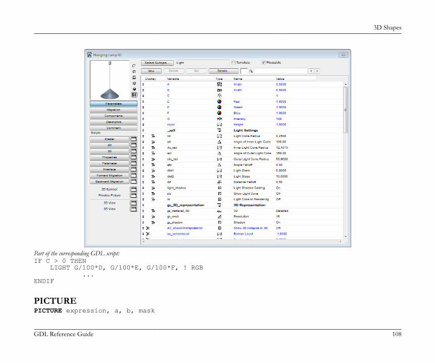
3D Shapes
GDL Reference Guide 108
Part of the corresponding GDL script:IF C > 0 THEN LIGHT G/100*D, G/100*E, G/100*F, ! RGB ...ENDIF
PICTUREPICTURE expression, a, b, mask
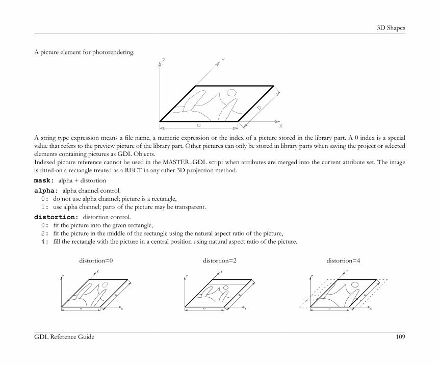
3D Shapes
GDL Reference Guide 109
A picture element for photorendering.
A string type expression means a file name, a numeric expression or the index of a picture stored in the library part. A 0 index is a specialvalue that refers to the preview picture of the library part. Other pictures can only be stored in library parts when saving the project or selectedelements containing pictures as GDL Objects.Indexed picture reference cannot be used in the MASTER_GDL script when attributes are merged into the current attribute set. The imageis fitted on a rectangle treated as a RECT in any other 3D projection method.mask: alpha + distortionalpha: alpha channel control.0: do not use alpha channel; picture is a rectangle,1: use alpha channel; parts of the picture may be transparent.
distortion: distortion control.0: fit the picture into the given rectangle,2: fit the picture in the middle of the rectangle using the natural aspect ratio of the picture,4: fill the rectangle with the picture in a central position using natural aspect ratio of the picture.
distortion=0 distortion=2 distortion=4
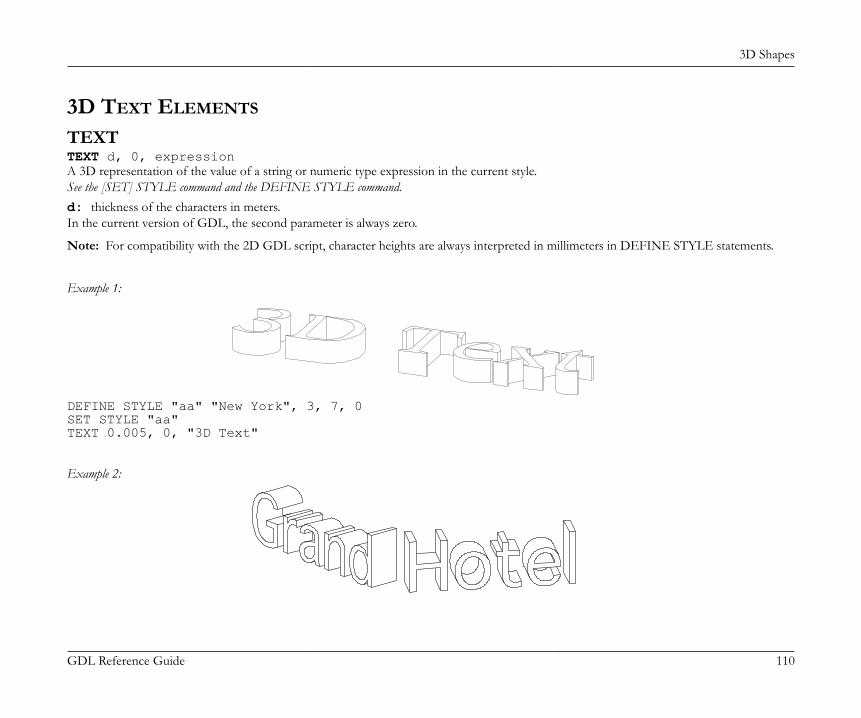
3D Shapes
GDL Reference Guide 110
3D TEXT ELEMENTS
TEXTTEXT d, 0, expressionA 3D representation of the value of a string or numeric type expression in the current style.See the [SET] STYLE command and the DEFINE STYLE command.d: thickness of the characters in meters.In the current version of GDL, the second parameter is always zero.
Note: For compatibility with the 2D GDL script, character heights are always interpreted in millimeters in DEFINE STYLE statements.
Example 1:
DEFINE STYLE "aa" "New York", 3, 7, 0SET STYLE "aa"TEXT 0.005, 0, "3D Text"
Example 2:
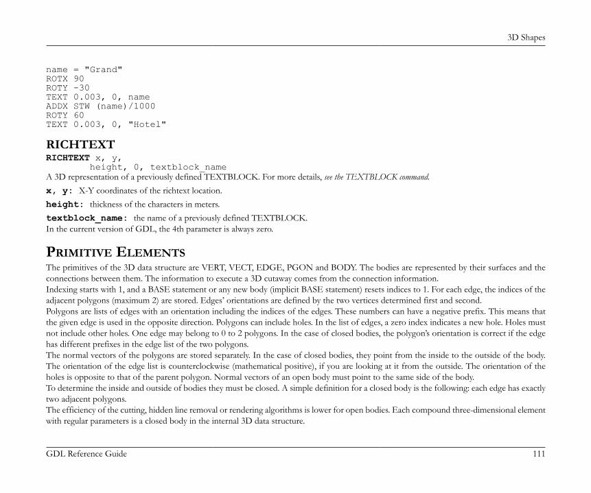
3D Shapes
GDL Reference Guide 111
name = "Grand"ROTX 90ROTY -30TEXT 0.003, 0, nameADDX STW (name)/1000ROTY 60TEXT 0.003, 0, "Hotel"
RICHTEXTRICHTEXT x, y, height, 0, textblock_nameA 3D representation of a previously defined TEXTBLOCK. For more details, see the TEXTBLOCK command.x, y: X-Y coordinates of the richtext location.height: thickness of the characters in meters.textblock_name: the name of a previously defined TEXTBLOCK.In the current version of GDL, the 4th parameter is always zero.
PRIMITIVE ELEMENTSThe primitives of the 3D data structure are VERT, VECT, EDGE, PGON and BODY. The bodies are represented by their surfaces and theconnections between them. The information to execute a 3D cutaway comes from the connection information.Indexing starts with 1, and a BASE statement or any new body (implicit BASE statement) resets indices to 1. For each edge, the indices of theadjacent polygons (maximum 2) are stored. Edges’ orientations are defined by the two vertices determined first and second.Polygons are lists of edges with an orientation including the indices of the edges. These numbers can have a negative prefix. This means thatthe given edge is used in the opposite direction. Polygons can include holes. In the list of edges, a zero index indicates a new hole. Holes mustnot include other holes. One edge may belong to 0 to 2 polygons. In the case of closed bodies, the polygon’s orientation is correct if the edgehas different prefixes in the edge list of the two polygons.The normal vectors of the polygons are stored separately. In the case of closed bodies, they point from the inside to the outside of the body.The orientation of the edge list is counterclockwise (mathematical positive), if you are looking at it from the outside. The orientation of theholes is opposite to that of the parent polygon. Normal vectors of an open body must point to the same side of the body.To determine the inside and outside of bodies they must be closed. A simple definition for a closed body is the following: each edge has exactlytwo adjacent polygons.The efficiency of the cutting, hidden line removal or rendering algorithms is lower for open bodies. Each compound three-dimensional elementwith regular parameters is a closed body in the internal 3D data structure.
3D Shapes
GDL Reference Guide 112
Contour line searching is based on the status bits of edges and on their adjacent polygons. This is automatically set for compound curvedelements but it is up to you to specify these bits correctly in the case of primitive elements.In the case of a simplified definition (vect = 0 or status < 0 in a PGON) the primitives that are referred to by others must precede theirreference. In this case, the recommended order is:VERT (TEVE)EDGE(VECT)PGON (PIPG)COORBODYSearching for adjacent polygons by the edges is done during the execution of the BODY command.The numbering of VERTs, EDGEs, VECTs and PGONs is relative to the last (explicit or implicit) BASE statement.Status values are used to store special information about primitives. Each single bit usually has an independent meaning in the status, but thereare some exceptions.Given values can be added together. Other bit combinations than the ones given below are strictly reserved for internal use. The default foreach status is zero.
VERTVERT x, y, zA node in the x-y-z space, defined by three coordinates.
TEVETEVE x, y, z, u, vExtension of the VERT command including a texture coordinate definition. Can be used instead of the VERT command if user-defined texturecoordinates are required instead of the automatic texture wrapping (see the COOR command).x, y, z: coordinates of a node.u, v: texture coordinates of the node (u, v) coordinates for each vertex of the current body must be specified and each vertex should have
only one texture coordinate. If VERT and TEVE statements are mixed inside a body definition, (u, v) coordinates are ineffective.
Note: The (u, v) texture coordinates are only effective in photorenderings, and not for vectorial fill mapping.
VECTVECT x, y, zDefinition of the normal vector of a polygon by three coordinates. In case of a simplified definition (vect=0 in a PGON), these statementscan be omitted.
3D Shapes
GDL Reference Guide 113
EDGEEDGE vert1, vert2, pgon1, pgon2, statusDefinition of an edge.vert1, vert2: index of the endpoints. The vert1 and vert2 indices must be different and referenced to previously defined VERTs.pgon1, pgon2: indices of the neighboring polygons. Zero and negative values have special meanings:0: terminal or standalone edge,< 0: possible neighbors will be searched for,
status: Status bits:status = j1 + 2*j2 + 4*j3 + 8*j4 + 16*j5 + 32*j6 + 64*j7, where each j can be 0 or 1.j1: invisible edge,j2: edge of a curved surface.Reserved status bits for future use:j3: first edge of a curved surface (effective only when j2=1),j4: last edge of a curved surface (effective only when j2=1),j5: the edge is an arc segment,j6: first segment of an arc (effective only when j4=1),j7: last segment of an arc (effective only when j4=1).
PGONPGON n, vect, status, edge1, edge2, ... edgenPolygon definition.n: number of edges in the edge list.vect: index of the normal vector. It must refer to a previously defined VECT.
Note: If vect = 0, the program will calculate the normal vector during the analysis.edge1, edge2, ... edgen: these indices must refer to previously defined EDGEs. A zero value means the beginning or the end
of a hole definition. A negative index changes the direction of the stored normal vector or edge to the opposite in the polygon. (The storedvector or edge does not change; other polygons can refer to it using the original orientation with a positive index.)
status: Status bits:status = j1 + 2*j2 + 16*j5 + 32*j6 + 64*j7 + 4*j3 + 8*j4, where each j can be 0 or 1.j1: invisible polygon,
3D Shapes
GDL Reference Guide 114
j2: polygon of a curved surface,j5: concave polygon,j6: polygon with hole(s),j7: hole(s) are convex (effective only when j6=1),Reserved status bits for future use:j3: first polygon of a curved surface (effective only when j2=1),j4: last polygon of a curved surface (effective only when j2=1).
If the status value is negative, the engine will calculate the status of the polygon (like concave polygon or polygon with hole).n = 0 is allowed for special purposes.
PGON{2}PGON{2} n, vect, status, wrap, edge_or_wrap1, ..., edge_or_wrapnThe first three parameters are similar to the ones at the PGON command.wrap: wrapping mode + projection type.0: the global wrapping mode is applied,> 0: the meaning is the same as it is in the COOR command.
edge_or_wrap1, ..., edge_or_wrapn: The number and meaning of these parameters are based on the wrap definition:edge1, ..., edgen: if wrap is 0; in this case edgen means the same as at the PGON command, and globally defined texturemapping will be applied;x1, y1, z1, x2, y2, z2, x3, y3, z3, x4, y4, z4, edge1, ..., edgen: if wrapping mode isn't 0 in wrap;in this case xi, yi, zi coordinates defining the coordinate system of the texture mapping for the polygon;edge1, u1, v1, ..., edgen, un, vn: if wrapping mode is 0 but projection type isn't 0 in wrap; in this case ui, vi texturespace coordinates are the same as at the TEVE command; the mapping will affect the currently defined polygon only.
PIPGPIPG expression, a, b, mask, n, vect, status, edge1, edge2, ... edgenPicture polygon definition. The first four parameters are the same as in the PICTURE element; the remaining ones are the same as in thePGON element.
COORCOOR wrap, vert1, vert2, vert3, vert4
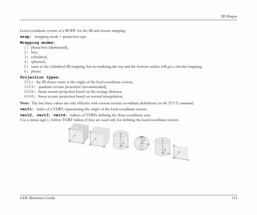
3D Shapes
GDL Reference Guide 115
Local coordinate system of a BODY for the fill and texture mapping.wrap: wrapping mode + projection typeWrapping modes:1: planar box (deprecated),2: box,3: cylindrical,4: spherical,5: same as the cylindrical fill mapping, but in rendering the top and the bottom surface will get a circular mapping,6: planar.
Projection types:256: the fill always starts at the origin of the local coordinate system,1024: quadratic texture projection (recommended),2048: linear texture projection based on the average distance,4096: linear texture projection based on normal triangulation.
Note: The last three values are only effective with custom texture coordinate definitions (see the TEVE command).vert1: index of a VERT, representing the origin of the local coordinate system.vert2, vert3, vert4: indices of VERTs defining the three coordinate axes.Use a minus sign (-) before VERT indices if they are used only for defining the local coordinate system.
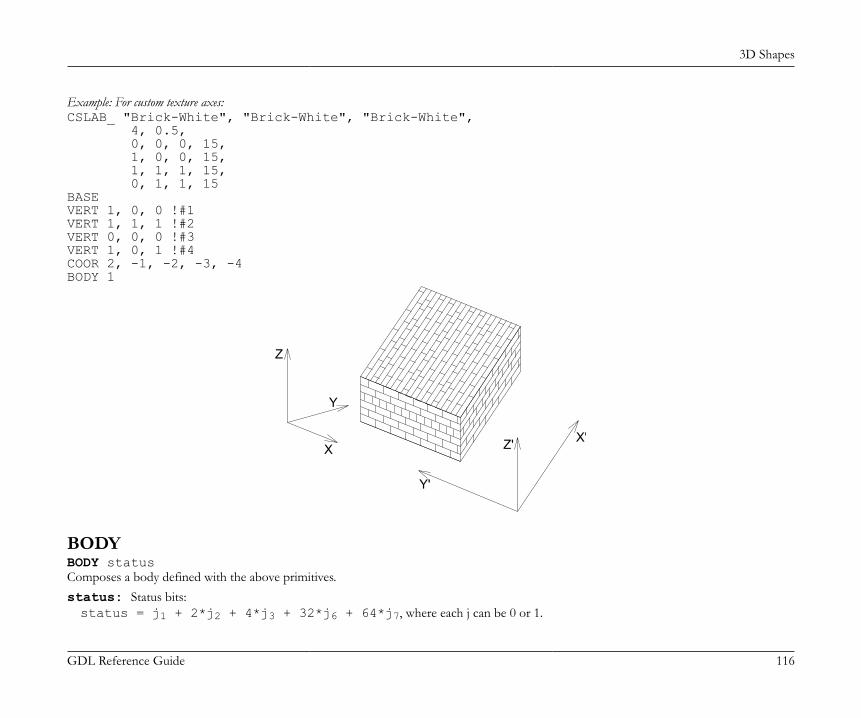
3D Shapes
GDL Reference Guide 116
Example: For custom texture axes:CSLAB_ "Brick-White", "Brick-White", "Brick-White", 4, 0.5, 0, 0, 0, 15, 1, 0, 0, 15, 1, 1, 1, 15, 0, 1, 1, 15BASEVERT 1, 0, 0 !#1VERT 1, 1, 1 !#2VERT 0, 0, 0 !#3VERT 1, 0, 1 !#4COOR 2, -1, -2, -3, -4BODY 1
X
Y
X'
Y'
Z
Z'
BODYBODY statusComposes a body defined with the above primitives.status: Status bits:status = j1 + 2*j2 + 4*j3 + 32*j6 + 64*j7, where each j can be 0 or 1.
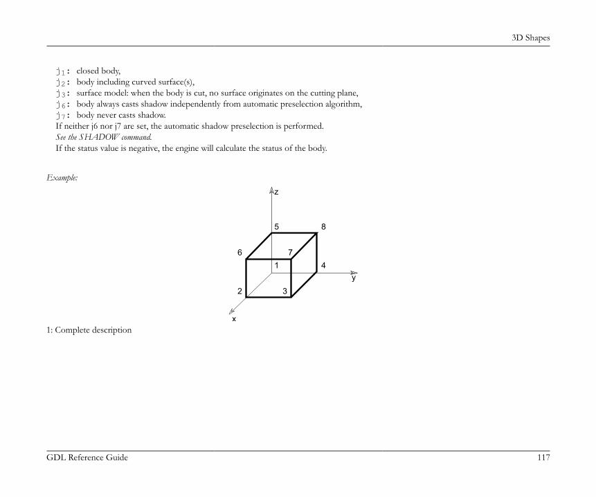
3D Shapes
GDL Reference Guide 117
j1: closed body,j2: body including curved surface(s),j3: surface model: when the body is cut, no surface originates on the cutting plane,j6: body always casts shadow independently from automatic preselection algorithm,j7: body never casts shadow.If neither j6 nor j7 are set, the automatic shadow preselection is performed.See the SHADOW command.If the status value is negative, the engine will calculate the status of the body.
Example:
x
y
z
1
2 3
4
5
6 7
8
1: Complete description
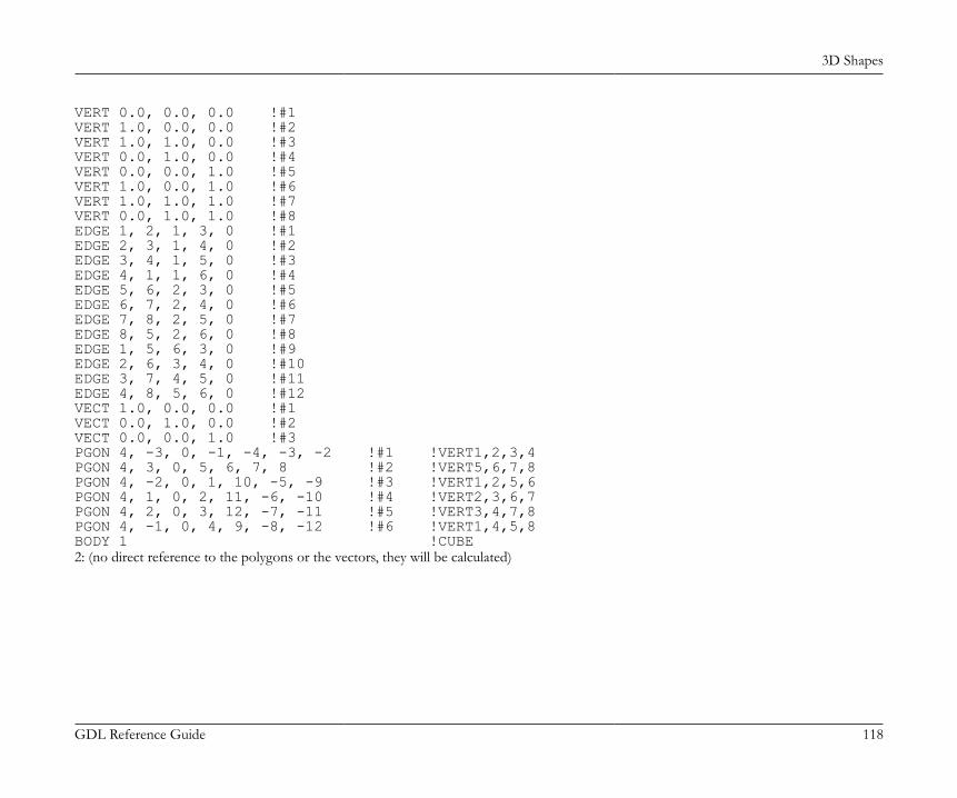
3D Shapes
GDL Reference Guide 118
VERT 0.0, 0.0, 0.0 !#1VERT 1.0, 0.0, 0.0 !#2VERT 1.0, 1.0, 0.0 !#3VERT 0.0, 1.0, 0.0 !#4VERT 0.0, 0.0, 1.0 !#5VERT 1.0, 0.0, 1.0 !#6VERT 1.0, 1.0, 1.0 !#7VERT 0.0, 1.0, 1.0 !#8EDGE 1, 2, 1, 3, 0 !#1EDGE 2, 3, 1, 4, 0 !#2EDGE 3, 4, 1, 5, 0 !#3EDGE 4, 1, 1, 6, 0 !#4EDGE 5, 6, 2, 3, 0 !#5EDGE 6, 7, 2, 4, 0 !#6EDGE 7, 8, 2, 5, 0 !#7EDGE 8, 5, 2, 6, 0 !#8EDGE 1, 5, 6, 3, 0 !#9EDGE 2, 6, 3, 4, 0 !#10EDGE 3, 7, 4, 5, 0 !#11EDGE 4, 8, 5, 6, 0 !#12VECT 1.0, 0.0, 0.0 !#1VECT 0.0, 1.0, 0.0 !#2VECT 0.0, 0.0, 1.0 !#3PGON 4, -3, 0, -1, -4, -3, -2 !#1 !VERT1,2,3,4PGON 4, 3, 0, 5, 6, 7, 8 !#2 !VERT5,6,7,8PGON 4, -2, 0, 1, 10, -5, -9 !#3 !VERT1,2,5,6PGON 4, 1, 0, 2, 11, -6, -10 !#4 !VERT2,3,6,7PGON 4, 2, 0, 3, 12, -7, -11 !#5 !VERT3,4,7,8PGON 4, -1, 0, 4, 9, -8, -12 !#6 !VERT1,4,5,8BODY 1 !CUBE2: (no direct reference to the polygons or the vectors, they will be calculated)
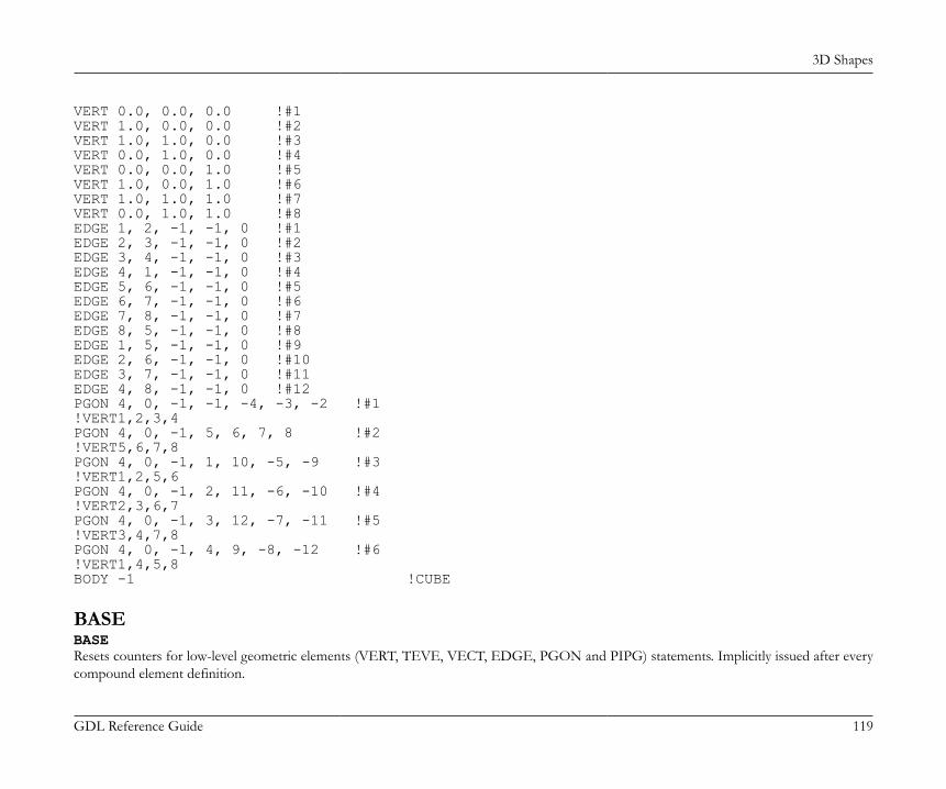
3D Shapes
GDL Reference Guide 119
VERT 0.0, 0.0, 0.0 !#1VERT 1.0, 0.0, 0.0 !#2VERT 1.0, 1.0, 0.0 !#3VERT 0.0, 1.0, 0.0 !#4VERT 0.0, 0.0, 1.0 !#5VERT 1.0, 0.0, 1.0 !#6VERT 1.0, 1.0, 1.0 !#7VERT 0.0, 1.0, 1.0 !#8EDGE 1, 2, -1, -1, 0 !#1EDGE 2, 3, -1, -1, 0 !#2EDGE 3, 4, -1, -1, 0 !#3EDGE 4, 1, -1, -1, 0 !#4EDGE 5, 6, -1, -1, 0 !#5EDGE 6, 7, -1, -1, 0 !#6EDGE 7, 8, -1, -1, 0 !#7EDGE 8, 5, -1, -1, 0 !#8EDGE 1, 5, -1, -1, 0 !#9EDGE 2, 6, -1, -1, 0 !#10EDGE 3, 7, -1, -1, 0 !#11EDGE 4, 8, -1, -1, 0 !#12PGON 4, 0, -1, -1, -4, -3, -2 !#1!VERT1,2,3,4PGON 4, 0, -1, 5, 6, 7, 8 !#2!VERT5,6,7,8PGON 4, 0, -1, 1, 10, -5, -9 !#3!VERT1,2,5,6PGON 4, 0, -1, 2, 11, -6, -10 !#4!VERT2,3,6,7PGON 4, 0, -1, 3, 12, -7, -11 !#5!VERT3,4,7,8PGON 4, 0, -1, 4, 9, -8, -12 !#6!VERT1,4,5,8BODY -1 !CUBE
BASEBASEResets counters for low-level geometric elements (VERT, TEVE, VECT, EDGE, PGON and PIPG) statements. Implicitly issued after everycompound element definition.
3D Shapes
GDL Reference Guide 120
CUTTING IN 3DCUTPLANECUTPLANE [x [, y [, z [, side [, status]]]]][statement1 ... statementn]CUTEND
CUTPLANE{2}CUTPLANE{2} angle [, status][statement1 ... statementn]CUTEND
CUTPLANE{3}CUTPLANE{3} [x [, y [, z [, side [, status]]]]][statement1 ... statementn]CUTENDCreates a cutting plane and removes the cut parts of enclosed shapes. CUTPLANE may have a different number of parameters.If CUTPLANE has the following number of parameters:0: x-y plane;1: cutting plane goes across x axis, angle is between cutting plane and x-y plane;2: cutting plane is parallel to z axis, crosses x axis and y axis at the given values;3: cutting plane crosses the x, y and z axes at the given values;4: the first three parameters are as above, with the addition of the side value as follows:side: definition of the side to cut.0: removes parts above cutting plane (default),1: removes parts below cutting plane; in case of x-y, x-z, y-z, removes the parts in the negative direction of the axis.
status: status control of the cut surfaces.status = j1 + 2*j2 + 4*j3 + 256*j9, where each j can be 0 or 1.j1: use the attributes of the body for the generated polygons and edges.j2: generated cut polygons will be treated as normal polygons.j3: generated cut edges will be invisible.j9: vertices on the cutting plane are treated as removed.
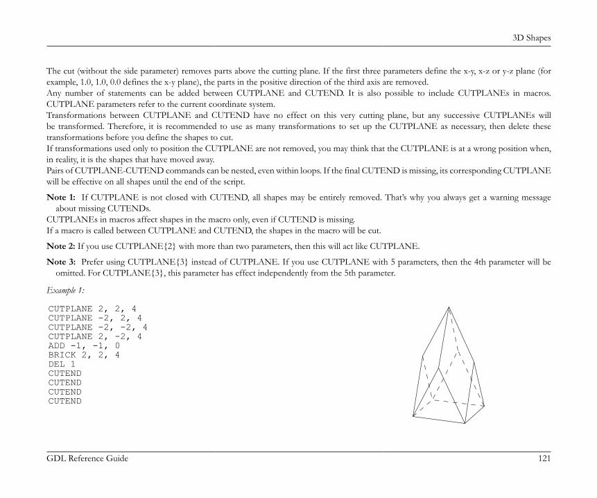
3D Shapes
GDL Reference Guide 121
The cut (without the side parameter) removes parts above the cutting plane. If the first three parameters define the x-y, x-z or y-z plane (forexample, 1.0, 1.0, 0.0 defines the x-y plane), the parts in the positive direction of the third axis are removed.Any number of statements can be added between CUTPLANE and CUTEND. It is also possible to include CUTPLANEs in macros.CUTPLANE parameters refer to the current coordinate system.Transformations between CUTPLANE and CUTEND have no effect on this very cutting plane, but any successive CUTPLANEs willbe transformed. Therefore, it is recommended to use as many transformations to set up the CUTPLANE as necessary, then delete thesetransformations before you define the shapes to cut.If transformations used only to position the CUTPLANE are not removed, you may think that the CUTPLANE is at a wrong position when,in reality, it is the shapes that have moved away.Pairs of CUTPLANE-CUTEND commands can be nested, even within loops. If the final CUTEND is missing, its corresponding CUTPLANEwill be effective on all shapes until the end of the script.
Note 1: If CUTPLANE is not closed with CUTEND, all shapes may be entirely removed. That’s why you always get a warning messageabout missing CUTENDs.
CUTPLANEs in macros affect shapes in the macro only, even if CUTEND is missing.If a macro is called between CUTPLANE and CUTEND, the shapes in the macro will be cut.
Note 2: If you use CUTPLANE{2} with more than two parameters, then this will act like CUTPLANE.
Note 3: Prefer using CUTPLANE{3} instead of CUTPLANE. If you use CUTPLANE with 5 parameters, then the 4th parameter will beomitted. For CUTPLANE{3}, this parameter has effect independently from the 5th parameter.
Example 1:
CUTPLANE 2, 2, 4CUTPLANE -2, 2, 4CUTPLANE -2, -2, 4CUTPLANE 2, -2, 4ADD -1, -1, 0BRICK 2, 2, 4DEL 1CUTENDCUTENDCUTENDCUTEND
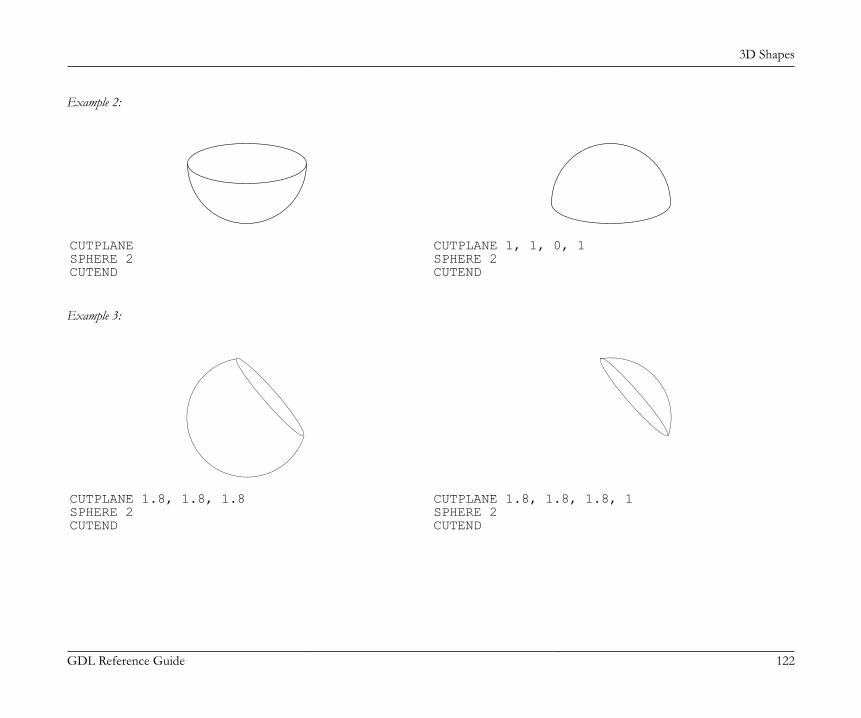
3D Shapes
GDL Reference Guide 122
Example 2:
CUTPLANESPHERE 2CUTEND
CUTPLANE 1, 1, 0, 1SPHERE 2CUTEND
Example 3:
CUTPLANE 1.8, 1.8, 1.8SPHERE 2CUTEND
CUTPLANE 1.8, 1.8, 1.8, 1SPHERE 2CUTEND
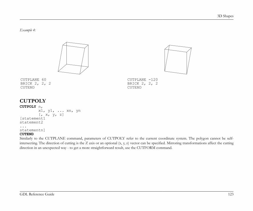
3D Shapes
GDL Reference Guide 123
Example 4:
CUTPLANE 60BRICK 2, 2, 2CUTEND
CUTPLANE -120BRICK 2, 2, 2CUTEND
CUTPOLYCUTPOLY n, x1, y1, ... xn, yn [, x, y, z][statement1statement2...statementn]CUTENDSimilarly to the CUTPLANE command, parameters of CUTPOLY refer to the current coordinate system. The polygon cannot be self-intersecting. The direction of cutting is the Z axis or an optional (x, y, z) vector can be specified. Mirroring transformations affect the cuttingdirection in an unexpected way - to get a more straightforward result, use the CUTFORM command.
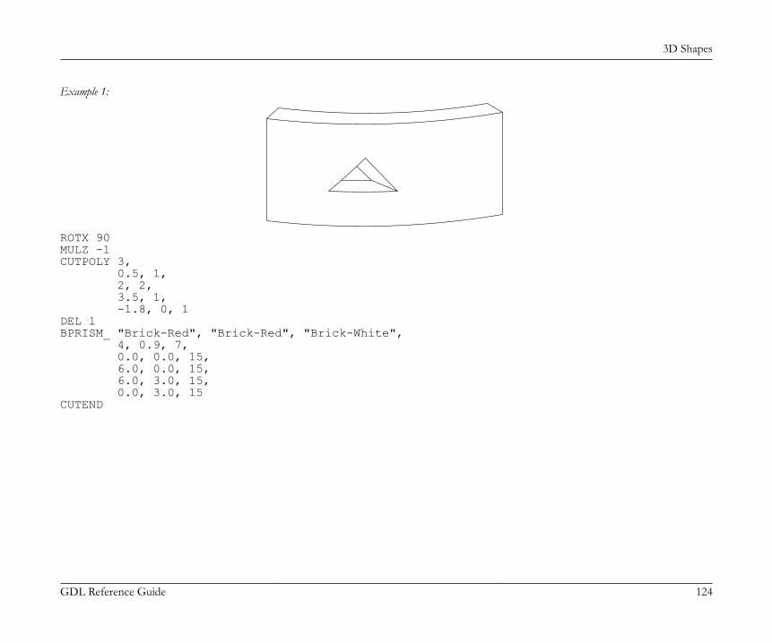
3D Shapes
GDL Reference Guide 124
Example 1:
ROTX 90MULZ -1CUTPOLY 3, 0.5, 1, 2, 2, 3.5, 1, -1.8, 0, 1DEL 1BPRISM_ "Brick-Red", "Brick-Red", "Brick-White", 4, 0.9, 7, 0.0, 0.0, 15, 6.0, 0.0, 15, 6.0, 3.0, 15, 0.0, 3.0, 15CUTEND
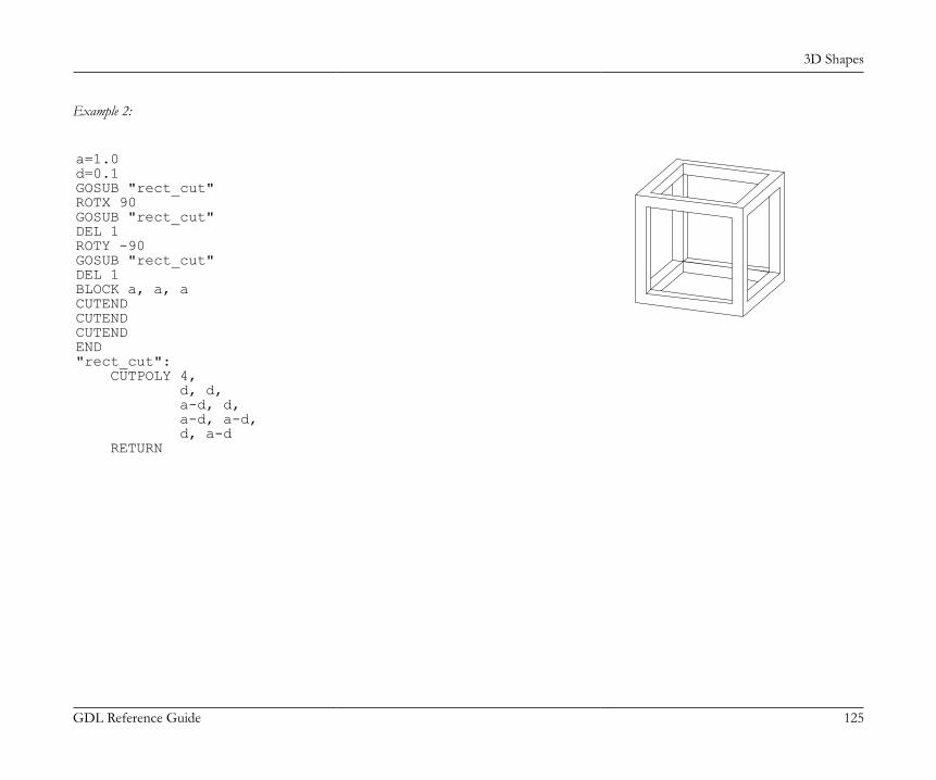
3D Shapes
GDL Reference Guide 125
Example 2:
a=1.0d=0.1GOSUB "rect_cut"ROTX 90GOSUB "rect_cut"DEL 1ROTY -90GOSUB "rect_cut"DEL 1BLOCK a, a, aCUTENDCUTENDCUTENDEND"rect_cut": CUTPOLY 4, d, d, a-d, d, a-d, a-d, d, a-d RETURN
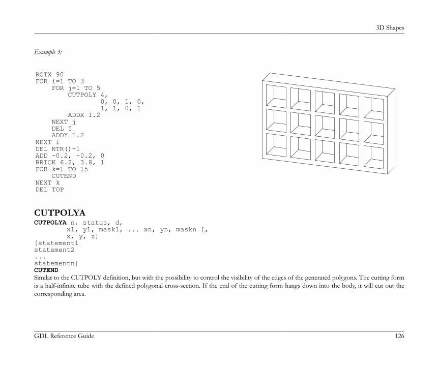
3D Shapes
GDL Reference Guide 126
Example 3:
ROTX 90FOR i=1 TO 3 FOR j=1 TO 5 CUTPOLY 4, 0, 0, 1, 0, 1, 1, 0, 1 ADDX 1.2 NEXT j DEL 5 ADDY 1.2NEXT iDEL NTR()-1ADD -0.2, -0.2, 0BRICK 6.2, 3.8, 1FOR k=1 TO 15 CUTENDNEXT kDEL TOP
CUTPOLYACUTPOLYA n, status, d, x1, y1, mask1, ... xn, yn, maskn [, x, y, z][statement1statement2...statementn]CUTENDSimilar to the CUTPOLY definition, but with the possibility to control the visibility of the edges of the generated polygons. The cutting formis a half-infinite tube with the defined polygonal cross-section. If the end of the cutting form hangs down into the body, it will cut out thecorresponding area.
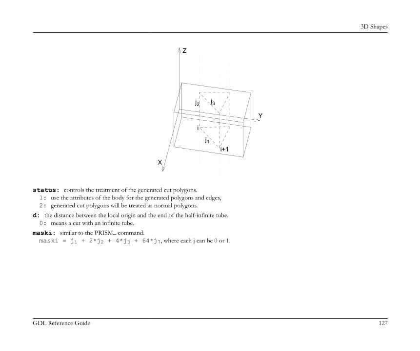
3D Shapes
GDL Reference Guide 127
i
Y
X
Z
jj
ji+1
1
2 3
status: controls the treatment of the generated cut polygons.1: use the attributes of the body for the generated polygons and edges,2: generated cut polygons will be treated as normal polygons.
d: the distance between the local origin and the end of the half-infinite tube.0: means a cut with an infinite tube.
maski: similar to the PRISM_ command.maski = j1 + 2*j2 + 4*j3 + 64*j7, where each j can be 0 or 1.
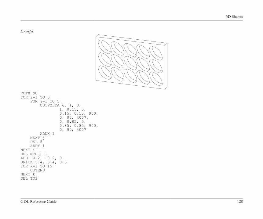
3D Shapes
GDL Reference Guide 128
Example:
ROTX 90FOR i=1 TO 3 FOR j=1 TO 5 CUTPOLYA 6, 1, 0, 1, 0.15, 5, 0.15, 0.15, 900, 0, 90, 4007, 0, 0.85, 5, 0.85, 0.85, 900, 0, 90, 4007 ADDX 1 NEXT j DEL 5 ADDY 1NEXT iDEL NTR()-1ADD -0.2, -0.2, 0BRICK 5.4, 3.4, 0.5FOR k=1 TO 15 CUTENDNEXT kDEL TOP
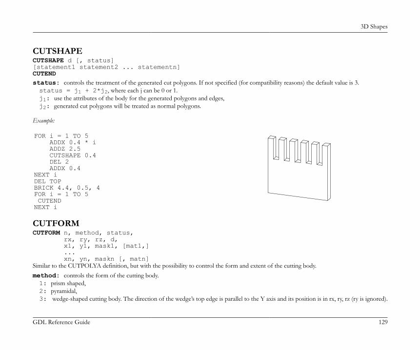
3D Shapes
GDL Reference Guide 129
CUTSHAPECUTSHAPE d [, status][statement1 statement2 ... statementn]CUTENDstatus: controls the treatment of the generated cut polygons. If not specified (for compatibility reasons) the default value is 3.status = j1 + 2*j2, where each j can be 0 or 1.j1: use the attributes of the body for the generated polygons and edges,j2: generated cut polygons will be treated as normal polygons.
Example:
FOR i = 1 TO 5 ADDX 0.4 * i ADDZ 2.5 CUTSHAPE 0.4 DEL 2 ADDX 0.4NEXT iDEL TOPBRICK 4.4, 0.5, 4FOR i = 1 TO 5 CUTENDNEXT i
CUTFORMCUTFORM n, method, status, rx, ry, rz, d, x1, y1, mask1, [mat1,] ... xn, yn, maskn [, matn]Similar to the CUTPOLYA definition, but with the possibility to control the form and extent of the cutting body.method: controls the form of the cutting body.1: prism shaped,2: pyramidal,3: wedge-shaped cutting body. The direction of the wedge’s top edge is parallel to the Y axis and its position is in rx, ry, rz (ry is ignored).
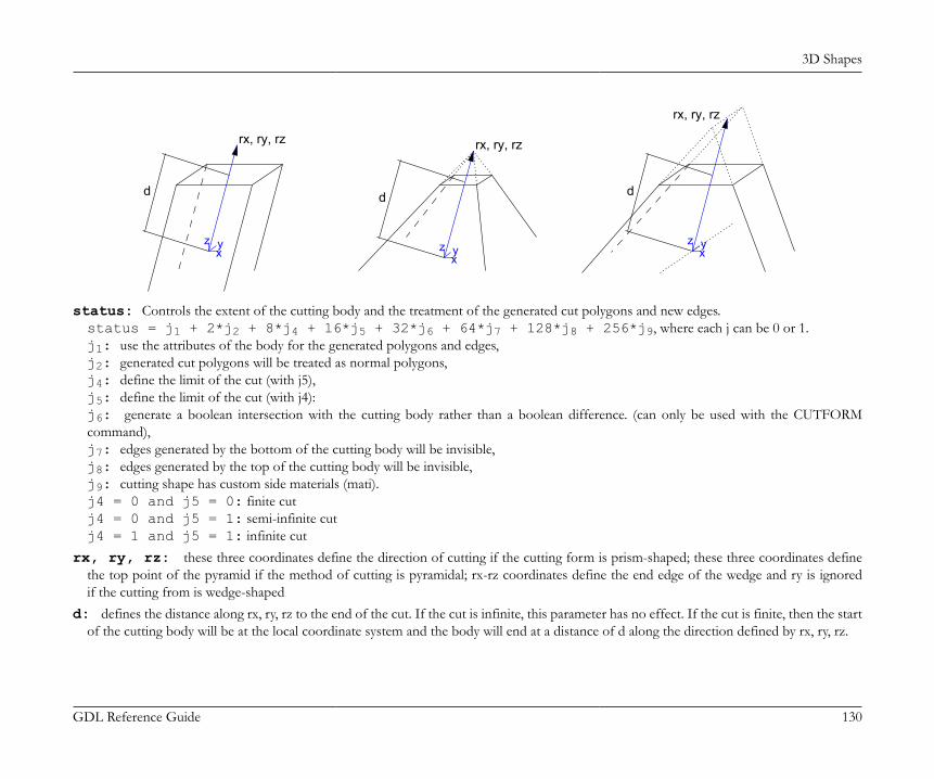
3D Shapes
GDL Reference Guide 130
rx, ry, rz
d
z x y
rx, ry, rz
d
z x y
rx, ry, rz
d
z x y
status: Controls the extent of the cutting body and the treatment of the generated cut polygons and new edges.status = j1 + 2*j2 + 8*j4 + 16*j5 + 32*j6 + 64*j7 + 128*j8 + 256*j9, where each j can be 0 or 1.j1: use the attributes of the body for the generated polygons and edges,j2: generated cut polygons will be treated as normal polygons,j4: define the limit of the cut (with j5),j5: define the limit of the cut (with j4):j6: generate a boolean intersection with the cutting body rather than a boolean difference. (can only be used with the CUTFORMcommand),j7: edges generated by the bottom of the cutting body will be invisible,j8: edges generated by the top of the cutting body will be invisible,j9: cutting shape has custom side materials (mati).j4 = 0 and j5 = 0: finite cutj4 = 0 and j5 = 1: semi-infinite cutj4 = 1 and j5 = 1: infinite cut
rx, ry, rz: these three coordinates define the direction of cutting if the cutting form is prism-shaped; these three coordinates definethe top point of the pyramid if the method of cutting is pyramidal; rx-rz coordinates define the end edge of the wedge and ry is ignoredif the cutting from is wedge-shaped
d: defines the distance along rx, ry, rz to the end of the cut. If the cut is infinite, this parameter has no effect. If the cut is finite, then the startof the cutting body will be at the local coordinate system and the body will end at a distance of d along the direction defined by rx, ry, rz.
3D Shapes
GDL Reference Guide 131
If the cut is semi-infinite, then the start of the cutting body will be at a distance of d along the direction defined by rx, ry, rz, and the directionof the semi-infinite cut will be in the opposite direction defined by rx, ry, rz.
mask: defines the visibility of the edges of the cutting body.mask = j1 + 2*j2 + 4*j3 + 8*j4 + 16*j5 + 64*j7, where each j can be 0 or 1.j1: the polygon will create a visible edge upon entry into the body being cut,j2: the lengthwise edge of the cutting form will be visible,j3: polygon will create a visible edge upon exiting the body being cut,j4: the bottom edge of the cutting form will be visible,j5: the top edge of the cutting form will be visible,j7: controls the viewpoint dependent visibility of the lengthwise edge.
mati: side material of the cutting shape (when status j9 = 1)
SOLID GEOMETRY COMMANDSGDL is capable of performing specialized 3D operations between solids represented by groups. These operations can be one of the following:
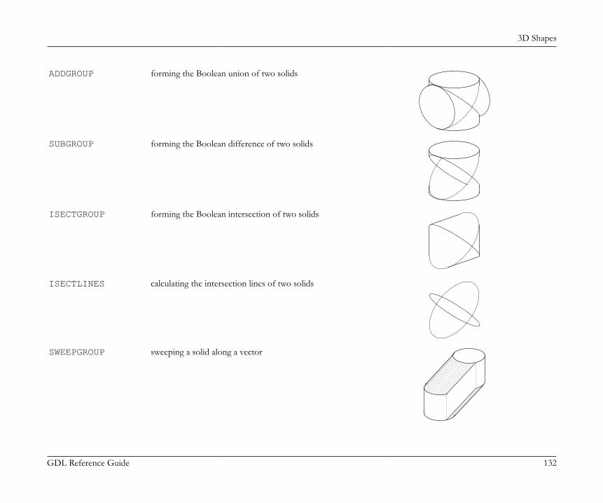
3D Shapes
GDL Reference Guide 132
ADDGROUP forming the Boolean union of two solids
SUBGROUP forming the Boolean difference of two solids
ISECTGROUP forming the Boolean intersection of two solids
ISECTLINES calculating the intersection lines of two solids
SWEEPGROUP sweeping a solid along a vector
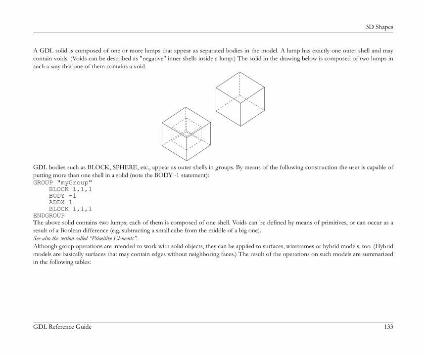
3D Shapes
GDL Reference Guide 133
A GDL solid is composed of one or more lumps that appear as separated bodies in the model. A lump has exactly one outer shell and maycontain voids. (Voids can be described as "negative" inner shells inside a lump.) The solid in the drawing below is composed of two lumps insuch a way that one of them contains a void.
GDL bodies such as BLOCK, SPHERE, etc., appear as outer shells in groups. By means of the following construction the user is capable ofputting more than one shell in a solid (note the BODY -1 statement):GROUP "myGroup" BLOCK 1,1,1 BODY -1 ADDX 1 BLOCK 1,1,1ENDGROUPThe above solid contains two lumps; each of them is composed of one shell. Voids can be defined by means of primitives, or can occur as aresult of a Boolean difference (e.g. subtracting a small cube from the middle of a big one).See also the section called “Primitive Elements”.Although group operations are intended to work with solid objects, they can be applied to surfaces, wireframes or hybrid models, too. (Hybridmodels are basically surfaces that may contain edges without neighboring faces.) The result of the operations on such models are summarizedin the following tables:
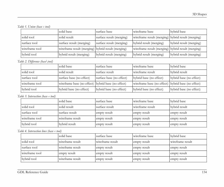
3D Shapes
GDL Reference Guide 134
Table 1. Union (base » tool)solid base surface base wireframe base hybrid base
solid tool solid result surface result (merging) wireframe result (merging) hybrid result (merging)
surface tool surface result (merging) surface result (merging) hybrid result (merging) hybrid result (merging)
wireframe tool wireframe result (merging) hybrid result (merging) wireframe result (merging) hybrid result (merging)
hybrid tool hybrid result (merging) hybrid result (merging) hybrid result (merging) hybrid result (merging)
Table 2. Difference (base\tool)solid base surface base wireframe base hybrid base
solid tool solid result surface result wireframe result hybrid result
surface tool surface base (no effect) surface base (no effect) hybrid base (no effect) hybrid base (no effect)
wireframe tool wireframe base (no effect) hybrid base (no effect) wireframe base (no effect) hybrid base (no effect)
hybrid tool hybrid base (no effect) hybrid base (no effect) hybrid base (no effect) hybrid base (no effect)
Table 3. Intersection (base « tool)solid base surface base wireframe base hybrid base
solid tool solid result surface result wireframe result hybrid result
surface tool surface result empty result empty result empty result
wireframe tool wireframe result empty result empty result empty result
hybrid tool hybrid result empty result empty result empty result
Table 4. Intersection lines (base « tool)solid base surface base wireframe base hybrid base
solid tool wireframe result wireframe result empty result wireframe result
surface tool wireframe result empty result empty result empty result
wireframe tool empty result empty result empty result empty result
hybrid tool wireframe result empty result empty result empty result
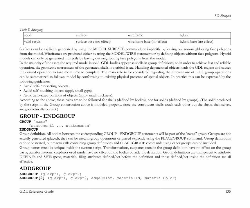
3D Shapes
GDL Reference Guide 135
Table 5. Sweepingsolid surface wireframe hybrid
valid result surface base (no effect) wireframe base (no effect) hybrid base (no effect)
Surfaces can be explicitly generated by using the MODEL SURFACE command, or implicitly by leaving out non-neighboring face polygonsfrom the model. Wireframes are produced either by using the MODEL WIRE statement or by defining objects without face polygons. Hybridmodels can only be generated indirectly by leaving out neighboring face polygons from the model.In the majority of the cases the required model is solid. GDL bodies appear as shells in group definitions, so in order to achieve fast and reliableoperation, the geometric correctness of the generated shells is a critical issue. Handling degenerated objects loads the GDL engine and causesthe desired operation to take more time to complete. The main rule to be considered regarding the efficient use of GDL group operationscan be summarized as follows: model by conforming to existing physical presence of spatial objects. In practice this can be expressed by thefollowing guidelines:• Avoid self-intersecting objects.• Avoid self-touching objects (apply small gaps).• Avoid zero-sized portions of objects (apply small thickness).According to the above, these rules are to be followed for shells (defined by bodies), not for solids (defined by groups). (The solid producedby the script in the Group construction above is modeled properly, since the constituent shells touch each other but the shells, themselves,are geometrically correct.)
GROUP - ENDGROUPGROUP "name" [statement1 ... statementn]ENDGROUPGroup definition. All bodies between the corresponding GROUP - ENDGROUP statements will be part of the "name" group. Groups are notactually generated (placed), they can be used in group operations or placed explicitly using the PLACEGROUP command. Group definitionscannot be nested, but macro calls containing group definitions and PLACEGROUP commands using other groups can be included.Group names must be unique inside the current script. Transformations, cutplanes outside the group definition have no effect on the groupparts; transformations, cutplanes used inside have no effect on the bodies outside the definition. Group definitions are transparent to attributeDEFINEs and SETs (pens, materials, fills); attributes defined/set before the definition and those defined/set inside the definition are alleffective.
ADDGROUPADDGROUP (g_expr1, g_expr2)ADDGROUP{2} (g_expr1, g_expr2, edgeColor, materialId, materialColor)
3D Shapes
GDL Reference Guide 136
SUBGROUPSUBGROUP (g_expr1, g_expr2)SUBGROUP{2} (g_expr1, g_expr2, edgeColor, materialId, materialColor)
ISECTGROUPISECTGROUP (g_expr1, g_expr2)ISECTGROUP{2} (g_expr1, g_expr2, edgeColor, materialId, materialColor)g_expr1: identifier of the base group.g_expr2: identifier of the tool group.edgeColor: the color of the new edge when it differs from 0.materialId: the material of the new face when it differs from 0.materialColor: the color of the new face when the materialId is 0 and it differs from 0.
ISECTLINESISECTLINES (g_expr1, g_expr2)Group operations: addition, subtraction, intersection, intersection lines. The return value is a new group, which can be placed using thePLACEGROUP command, stored in a variable or used as a parameter in another group operation. Group operations can be performedbetween previously defined groups or groups result from any other group operation. g_expr1, g_expr2 are group type expressions. Grouptype expressions are either group names (string expressions) or group type variables or any combination of these in operations which result ingroups. Note that the operations ADDGROUP, ISECTGROUP and ISECTLINES are symmetric in their parameterization while the orderof parameter matters for SUBGROUP.
PLACEGROUPPLACEGROUP g_exprPlacing a group is the operation in which bodies are actually generated. Cutplanes and transformations are effective, the group expression isevaluated and the resulting bodies are stored in the 3D data structure.
KILLGROUPKILLGROUP g_exprClears the bodies of the specified group from the memory. After a KILLGROUP operation the group becomes empty. The names of killedgroups cannot be reused in the same script. Clearing is executed automatically at the end of the interpretation or when returning from macrocalls. For performance reasons this command should be used when a group is no longer needed.
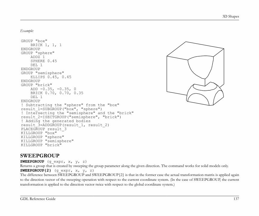
3D Shapes
GDL Reference Guide 137
Example:
GROUP "box" BRICK 1, 1, 1ENDGROUPGROUP "sphere" ADDZ 1 SPHERE 0.45 DEL 1ENDGROUPGROUP "semisphere" ELLIPS 0.45, 0.45ENDGROUPGROUP "brick" ADD -0.35, -0.35, 0 BRICK 0.70, 0.70, 0.35 DEL 1ENDGROUP! Subtracting the "sphere" from the "box"result_1=SUBGROUP("box", "sphere")! Intersecting the "semisphere" and the "brick"result_2=ISECTGROUP("semisphere", "brick")! Adding the generated bodiesresult_3=ADDGROUP(result_1, result_2)PLACEGROUP result_3KILLGROUP "box"KILLGROUP "sphere"KILLGROUP "semisphere"KILLGROUP "brick"
SWEEPGROUPSWEEPGROUP (g_expr, x, y, z)Returns a group that is created by sweeping the group parameter along the given direction. The command works for solid models only.SWEEPGROUP{2} (g_expr, x, y, z)The difference between SWEEPGROUP and SWEEPGROUP{2} is that in the former case the actual transformation matrix is applied againto the direction vector of the sweeping operation with respect to the current coordinate system. (In the case of SWEEPGROUP, the currenttransformation is applied to the direction vector twice with respect to the global coordinate system.)
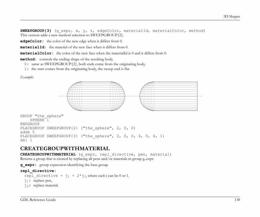
3D Shapes
GDL Reference Guide 138
SWEEPGROUP{3} (g_expr, x, y, z, edgeColor, materialId, materialColor, method)This version adds a new method selection to SWEEPGROUP{2}.edgeColor: the color of the new edge when it differs from 0.materialId: the material of the new face when it differs from 0.materialColor: the color of the new face when the materialId is 0 and it differs from 0.method: controls the ending shape of the resulting body.0: same as SWEEPGROUP{2}, both ends come from the originating body,1: the start comes from the originating body, the sweep end is flat
Example:
GROUP "the_sphere" SPHERE 1ENDGROUPPLACEGROUP SWEEPGROUP{2} ("the_sphere", 2, 0, 0)addx 5PLACEGROUP SWEEPGROUP{3} ("the_sphere", 2, 0, 0, 4, 0, 4, 1)del 1
CREATEGROUPWITHMATERIALCREATEGROUPWITHMATERIAL (g_expr, repl_directive, pen, material)Returns a group that is created by replacing all pens and/or materials in group g_expr.g_expr: group expression identifying the base group.repl_directive:repl_directive = j1 + 2*j2, where each j can be 0 or 1.j1: replace pen,j2: replace material.
3D Shapes
GDL Reference Guide 139
pen: replacement pen index.material: replacement material index.
BINARY 3DBINARYBINARY mode [, section]Special command to include inline binary objects into a GDL macro. A set of vertices, vectors, edges, polygons, bodies and materials is readfrom a special section of the library part file. These are transformed according to the current transformations and merged into the 3D model.The data contained in the binary section is not editable by the user.mode: defines pencolor and material attribute definition usage.0: the current PEN and MATERIAL settings are in effect,1: the current PEN and MATERIAL settings have no effect. The library part will be shown with the stored colors and material definitions.Surface appearance is constant,2: the stored PEN and MATERIAL settings are used, non-defined materials are replaced by current settings,3: the stored PEN and MATERIAL settings are used, non-defined materials are replaced by the stored default attributes.
section: index of the binary part, from 1 to 16.0: you can refer simultaneously to all the existing binary parts,1: Only these sections can be saved from within GDL, BINARY commands without the section argument will also refer to this,2-16: can be used by third party tools.
If you open files with a different data structure (e.g., DXF or ZOOM) their 3D description will be converted into binary format.You can save a library part in binary format from the main Library Part editing window through the Save as... command. If the Save in binaryformat checkbox is marked in the Save as... dialog box, the GDL text of the current library part will be replaced with a binary description.Hint: Saving the 3D model after a 3D cutaway operation in binary format will save the truncated model. This way, you can create cut shapes.You can only save your library part in binary format if you have already generated its 3D model.By replacing the GDL description of your library part with a binary description you can considerably reduce the 3D conversion time of theitem. On the other hand, the binary 3D description is not parametric and takes more disk space than an algorithmic GDL script.
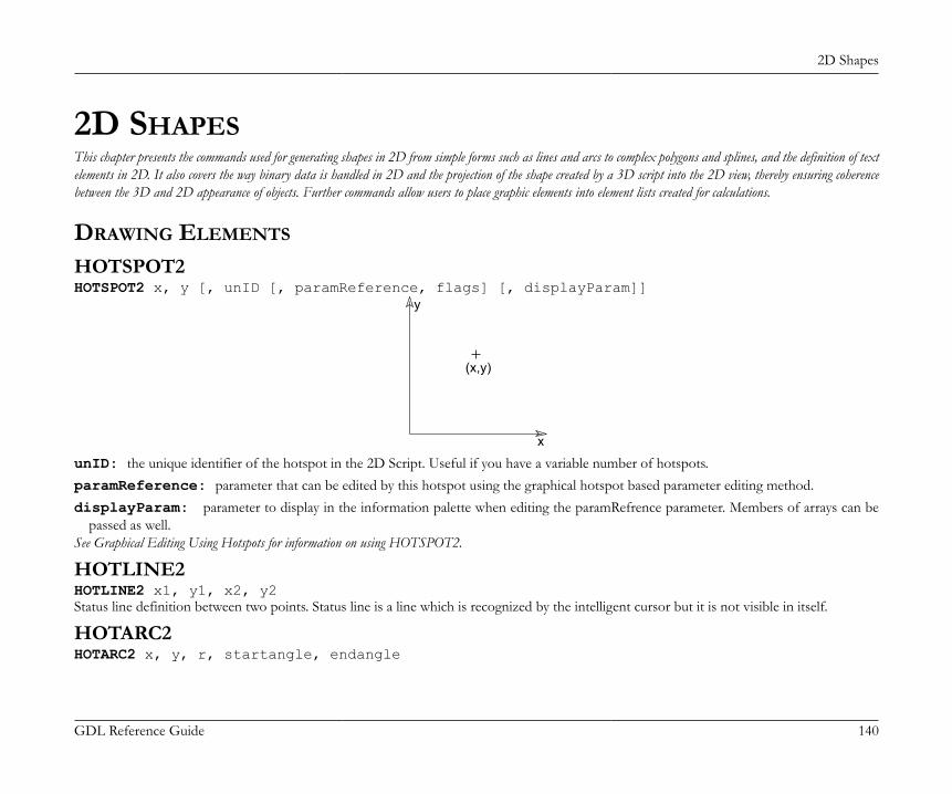
2D Shapes
GDL Reference Guide 140
2D SHAPESThis chapter presents the commands used for generating shapes in 2D from simple forms such as lines and arcs to complex polygons and splines, and the definition of textelements in 2D. It also covers the way binary data is handled in 2D and the projection of the shape created by a 3D script into the 2D view, thereby ensuring coherencebetween the 3D and 2D appearance of objects. Further commands allow users to place graphic elements into element lists created for calculations.
DRAWING ELEMENTS
HOTSPOT2HOTSPOT2 x, y [, unID [, paramReference, flags] [, displayParam]]
x
y
(x,y)
unID: the unique identifier of the hotspot in the 2D Script. Useful if you have a variable number of hotspots.paramReference: parameter that can be edited by this hotspot using the graphical hotspot based parameter editing method.displayParam: parameter to display in the information palette when editing the paramRefrence parameter. Members of arrays can be
passed as well.See Graphical Editing Using Hotspots for information on using HOTSPOT2.
HOTLINE2HOTLINE2 x1, y1, x2, y2Status line definition between two points. Status line is a line which is recognized by the intelligent cursor but it is not visible in itself.
HOTARC2HOTARC2 x, y, r, startangle, endangle
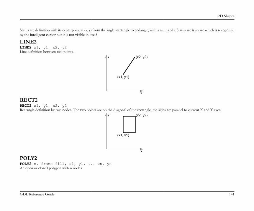
2D Shapes
GDL Reference Guide 141
Status arc definition with its centerpoint at (x, y) from the angle startangle to endangle, with a radius of r. Status arc is an arc which is recognizedby the intelligent cursor but it is not visible in itself.
LINE2LINE2 x1, y1, x2, y2Line definition between two points.
x
y
(x1, y1)
(x2, y2)
RECT2RECT2 x1, y1, x2, y2Rectangle definition by two nodes. The two points are on the diagonal of the rectangle, the sides are parallel to current X and Y axes.
x
y
(x1, y1)
(x2, y2)
POLY2POLY2 n, frame_fill, x1, y1, ... xn, ynAn open or closed polygon with n nodes.
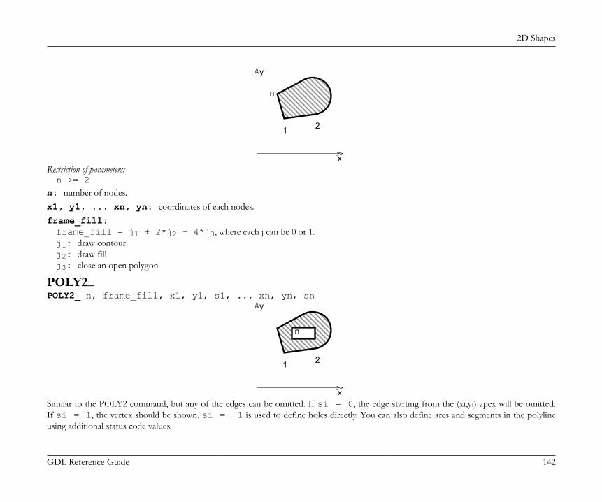
2D Shapes
GDL Reference Guide 142
x
y
1 2
n
Restriction of parameters:n >= 2
n: number of nodes.x1, y1, ... xn, yn: coordinates of each nodes.frame_fill:frame_fill = j1 + 2*j2 + 4*j3, where each j can be 0 or 1.j1: draw contourj2: draw fillj3: close an open polygon
POLY2_POLY2_ n, frame_fill, x1, y1, s1, ... xn, yn, sn
x
y
1 2
n
Similar to the POLY2 command, but any of the edges can be omitted. If si = 0, the edge starting from the (xi,yi) apex will be omitted.If si = 1, the vertex should be shown. si = -1 is used to define holes directly. You can also define arcs and segments in the polylineusing additional status code values.
2D Shapes
GDL Reference Guide 143
Restriction of parameters:n >= 2
n: number of nodes.x1, y1, ... xn, yn: coordinates of each nodes.frame_fill:frame_fill = j1 + 2*j2 + 4*j3 + 8*j4 + 32*j6 + 64*j7, where each j can be 0 or 1.j1: draw contour,j2: draw fill,j3: close an open polygon,j4: local fill orientation,j6: fill is cut fill (default is drafting fill),j7: fill is cover fill (only if j6 = 0, default is drafting fill).
si: Status values:si = j1 + 16*j5 + 32*j6, where each j can be 0 or 1.j1: next segment is visible,j5: next segment is inner line (if 0, generic line),j6: next segment is contour line (effective only if j5 is not set),-1: end of a contour.
Default line property for POLY2_ lines is 0 (generic line), the LINE_PROPERTY command has no effect on POLY2_ edges. Additional statuscodes allow you to create segments and arcs in the planar polyline using special constraints.See the section called “Additional Status Codes” for details.
POLY2_APOLY2_A n, frame_fill, fill_pen, x1, y1, s1, ..., xn, yn, sn
POLY2_BPOLY2_B n, frame_fill, fill_pen, fill_background_pen, x1, y1, s1, ..., xn, yn, snAdvanced versions of the POLY2_ command, with additional parameters: the fill pen and the fill background pen. All other parameters aresimilar to those described at the POLY2_ command.fill_pen: fill pencolor number.
2D Shapes
GDL Reference Guide 144
fill_background_pen: fill background pencolor number.Additional status codes allow you to create segments and arcs in the planar polyline using special constraints.See the section called “Additional Status Codes” for details.
POLY2_B{2}POLY2_B{2} n, frame_fill, fill_pen, fill_background_pen, fillOrigoX, fillOrigoY, fillAngle, x1, y1, s1, ..., xn, yn, snAdvanced version of the POLY2_B command where the hatching origin and direction can be defined.frame_fill:frame_fill = j1 + 2*j2 + 4*j3 + 8*j4 + 16*j5 + 32*j6 + 64*j7, where each j can be 0 or 1.j1: draw contourj2: draw fillj3: close an open polygonj4: local fill orientationj5: global fill origin (effective only if j4 is set)j6: fill in cut category (distinctive with j7, drafting category if none is set)j7: fill in cover category (distinctive with j6, drafting category if none is set).
fillOrigoX: X coordinate of the fill origin.fillOrigoY: Y coordinate of the fill origin.fillAngle: direction angle of fill.Additional status codes allow you to create segments and arcs in the planar polyline using special constraints.See the section called “Additional Status Codes” for details.
POLY2_B{3}POLY2_B{3} n, frame_fill, fill_pen, fill_background_pen, fillOrigoX, fillOrigoY, mxx, mxy, myx, myy, x1, y1, s1, ..., xn, yn, snAdvanced version of the POLY2_B command, where the orientation of the fill can be defined using a matrix.frame_fill:frame_fill = j1 + 2*j2 + 4*j3 + 8*j4 + 16*j5 + 32*j6 + 64*j7 + 128*j8, where each j can be 0 or 1.
2D Shapes
GDL Reference Guide 145
j1-j7: similar as for previous POLY2_ commands,j8: use sloped fill.
mxx, mxy, myx, myy: if j8 is set, this matrix defines the orientation of the fill.Additional status codes allow you to create segments and arcs in the planar polyline using special constraints.See the section called “Additional Status Codes” for details.
POLY2_B{4}POLY2_B{4} n, frame_fill, fill_pen, fill_background_pen, fillOrigoX, fillOrigoY, mxx, mxy, myx, myy, gradientInnerRadius, x1, y1, s1, ..., xn, yn, snAdvanced version of POLY2_ B{3}, where the inner radius of radial gradient fill can be set.gradientInnerRadius: inner radius of the gradient in case radial gradient fill is selected for the polygon.
POLY2_B{5}POLY2_B{5} n, frame_fill, fillcategory, distortion_flags, fill_pen, fill_background_pen, fillOrigoX, fillOrigoY, mxx, mxy, myx, myy, gradientInnerRadius, x1, y1, s1, ..., xn, yn, snAdvanced version of POLY2_ B{4}, where fill distortion can be controlled in an enhanced way.frame_fill:frame_fill = j1 + 2*j2 + 4*j3, where each j can be 0 or 1.j1: draw contourj2: draw fillj3: close an open polygon.
fillcategory:0: Draft,1: Cut,2: Cover.
distortion_flags:
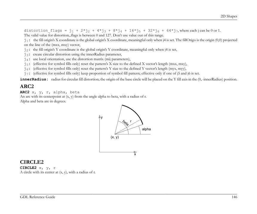
2D Shapes
GDL Reference Guide 146
distortion_flags = j1 + 2*j2 + 4*j3 + 8*j4 + 16*j5 + 32*j6 + 64*j7, where each j can be 0 or 1.The valid value for distortion_flags is between 0 and 127. Don’t use value out of this range.j1: the fill origin’s X coordinate is the global origin’s X coordinate, meaningful only when j4 is set. The fillOrigo is the origin (0,0) projectedon the line of the (mxx, mxy) vector,j2: the fill origin’s Y coordinate is the global origin’s Y coordinate, meaningful only when j4 is set,j3: create circular distortion using the innerRadius parameter,j4: use local orientation, use the distortion matrix (mij parameters),j5: (effective for symbol fills only) reset the pattern’s X size to the defined X vector’s length (mxx, mxy),j6: (effective for symbol fills only) reset the pattern’s Y size to the defined Y vector’s length (myx, myy),j7: (effective for symbol fills only) keep proportion of symbol fill pattern; effective only if one of j5 and j6 is set.
innerRadius: radius for circular fill distortion; the origin of the base circle will be placed on the Y fill axis in the (0, -innerRadius) position.
ARC2ARC2 x, y, r, alpha, betaAn arc with its centerpoint at (x, y) from the angle alpha to beta, with a radius of r.Alpha and beta are in degrees.
x
y
(x, y)
r
alpha
beta
CIRCLE2CIRCLE2 x, y, rA circle with its center at (x, y), with a radius of r.

2D Shapes
GDL Reference Guide 147
x
y r
(x, y)
SPLINE2SPLINE2 n, status, x1, y1, angle1, ..., xn, yn, anglen
x
y
1i
n
anglei
(xi,yi)
Spline, with n control points. The tangent of the spline in the control point (xi, yi) is defined by anglei, the angle with the x axis in degrees.Restriction of parameters:n >= 2
si: Status values:0: default,1: closed spline; the last and first nodes of the spline will become connected, thus closing the spline,2: automatically smoothed spline; the angle parameter value of the nodes between the first and the last node is not used when generatingthe spline. An internal autosmoothing algorithm is used.
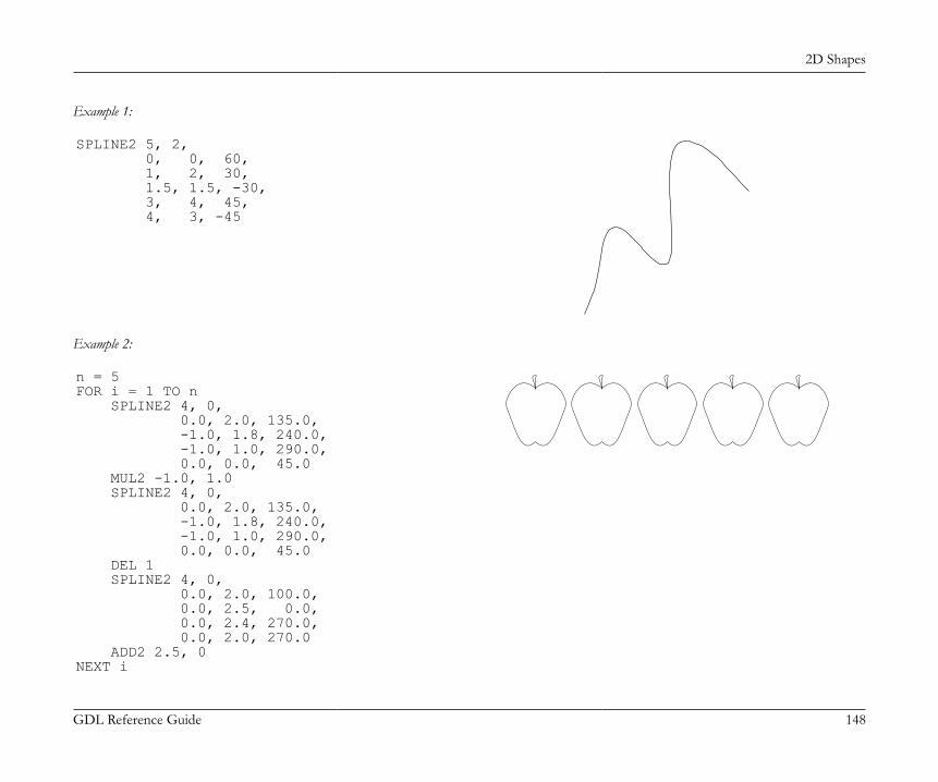
2D Shapes
GDL Reference Guide 148
Example 1:
SPLINE2 5, 2, 0, 0, 60, 1, 2, 30, 1.5, 1.5, -30, 3, 4, 45, 4, 3, -45
Example 2:
n = 5FOR i = 1 TO n SPLINE2 4, 0, 0.0, 2.0, 135.0, -1.0, 1.8, 240.0, -1.0, 1.0, 290.0, 0.0, 0.0, 45.0 MUL2 -1.0, 1.0 SPLINE2 4, 0, 0.0, 2.0, 135.0, -1.0, 1.8, 240.0, -1.0, 1.0, 290.0, 0.0, 0.0, 45.0 DEL 1 SPLINE2 4, 0, 0.0, 2.0, 100.0, 0.0, 2.5, 0.0, 0.0, 2.4, 270.0, 0.0, 2.0, 270.0 ADD2 2.5, 0NEXT i
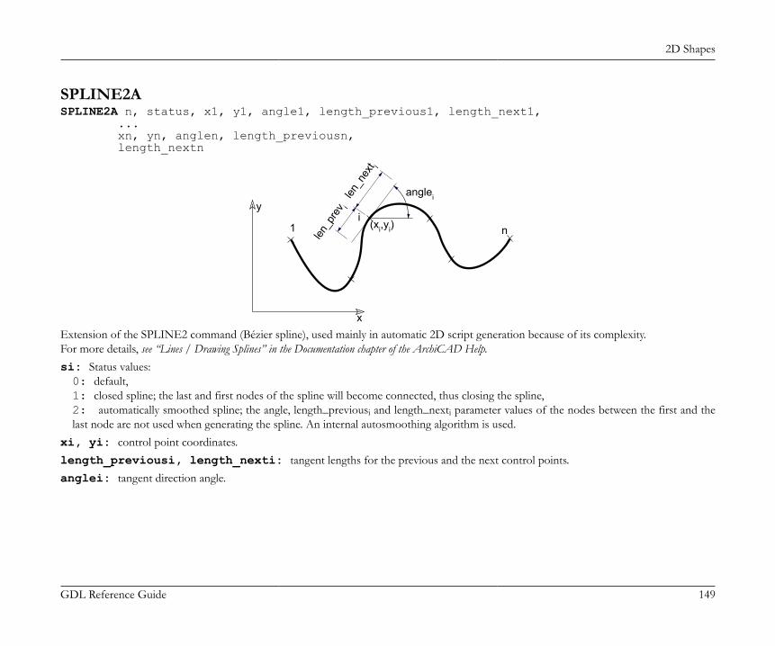
2D Shapes
GDL Reference Guide 149
SPLINE2ASPLINE2A n, status, x1, y1, angle1, length_previous1, length_next1, ... xn, yn, anglen, length_previousn, length_nextn
x
y
1i
n
anglei
(xi,yi)
len_p
rev i
len_n
ext i
Extension of the SPLINE2 command (Bézier spline), used mainly in automatic 2D script generation because of its complexity.For more details, see “Lines / Drawing Splines” in the Documentation chapter of the ArchiCAD Help.si: Status values:0: default,1: closed spline; the last and first nodes of the spline will become connected, thus closing the spline,2: automatically smoothed spline; the angle, length_previousi and length_nexti parameter values of the nodes between the first and thelast node are not used when generating the spline. An internal autosmoothing algorithm is used.
xi, yi: control point coordinates.length_previousi, length_nexti: tangent lengths for the previous and the next control points.anglei: tangent direction angle.
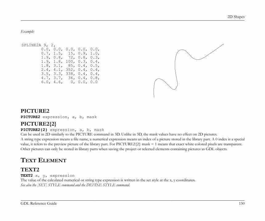
2D Shapes
GDL Reference Guide 150
Example:
SPLINE2A 9, 2, 0.0, 0.0, 0.0, 0.0, 0.0, 0.7, 1.5, 15, 0.9, 1.0, 1.9, 0.8, 72, 0.8, 0.3, 1.9, 1.8, 100, 0.3, 0.4, 1.8, 3.1, 85, 0.4, 0.5, 2.4, 4.1, 352, 0.4, 0.4, 3.5, 3.3, 338, 0.4, 0.4, 4.7, 3.7, 36, 0.4, 0.8, 6.0, 4.6, 0, 0.0, 0.0
PICTURE2PICTURE2 expression, a, b, mask
PICTURE2{2}PICTURE2{2} expression, a, b, maskCan be used in 2D similarly to the PICTURE command in 3D. Unlike in 3D, the mask values have no effect on 2D pictures.A string type expression means a file name, a numerical expression means an index of a picture stored in the library part. A 0 index is a specialvalue, it refers to the preview picture of the library part. For PICTURE2{2} mask = 1 means that exact white colored pixels are transparent.Other pictures can only be stored in library parts when saving the project or selected elements containing pictures as GDL objects.
TEXT ELEMENT
TEXT2TEXT2 x, y, expressionThe value of the calculated numerical or string type expression is written in the set style at the x, y coordinates.See also the [SET] STYLE command and the DEFINE STYLE command.
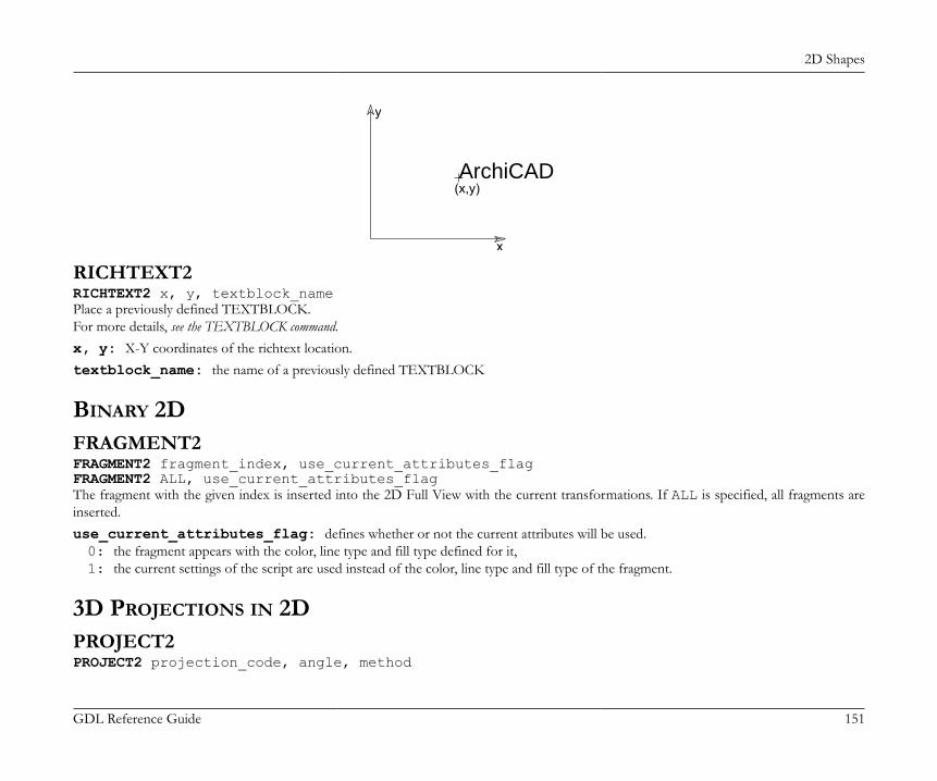
2D Shapes
GDL Reference Guide 151
x
y
(x,y)ArchiCAD
RICHTEXT2RICHTEXT2 x, y, textblock_namePlace a previously defined TEXTBLOCK.For more details, see the TEXTBLOCK command.x, y: X-Y coordinates of the richtext location.textblock_name: the name of a previously defined TEXTBLOCK
BINARY 2DFRAGMENT2FRAGMENT2 fragment_index, use_current_attributes_flagFRAGMENT2 ALL, use_current_attributes_flagThe fragment with the given index is inserted into the 2D Full View with the current transformations. If ALL is specified, all fragments areinserted.use_current_attributes_flag: defines whether or not the current attributes will be used.0: the fragment appears with the color, line type and fill type defined for it,1: the current settings of the script are used instead of the color, line type and fill type of the fragment.
3D PROJECTIONS IN 2DPROJECT2PROJECT2 projection_code, angle, method
2D Shapes
GDL Reference Guide 152
PROJECT2{2}PROJECT2{2} projection_code, angle, method [, backgroundColor, fillOrigoX, fillOrigoY, filldirection]Creates a projection of the 3D script in the same library part and adds the generated lines to the 2D parametric symbol. The 2nd versionPROJECT2{2}, together with a previous [SET] FILL command, allows the user to control the fill background, origin and direction ofthe resulting drawing from the 2D script. The SET FILL 0 shortcut to get an empty fill does not work in this case, you need to referencean actual empty fill.projection_code: the type of projection.3: Top view,4: Side view,6: Frontal axonometry,7: Isometric axonometry,8: Monometric axonometry,9: Dimetric axonometry,-3: Bottom view,-6: Frontal bottom view,-7: Isometric bottom view,-8: Monometric bottom view,-9: Dimetric bottom view.
angle: the azimuth angle set in the 3D Projection Settings dialog box.method: the chosen imaging method.1: wireframe,2: hidden lines (analytic),3: shading,16: addition modifier: draws vectorial hatches (effective only in hidden line and shaded mode),32: addition modifier: use current attributes instead of attributes from 3D (effective only in shading mode),64: addition modifier: local fill orientation (effective only in shading mode),128: addition modifier: lines are all inner lines (effective only together with 32). Default is generic,256: addition modifier: lines are all contour lines (effective only together with 32, if 128 is not set). Default is generic,512: addition modifier: fills are all cut (effective only together with 32). Default is drafting fills,1024: addition modifier: fills are all cover (effective only together with 32, if 512 is not set). Default is drafting fills.
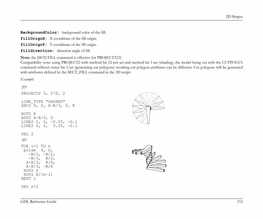
2D Shapes
GDL Reference Guide 153
BackgroundColor: background color of the fill.fillOrigoX: X coordinate of the fill origin.fillOrigoY: Y coordinate of the fill origin.filldirection: direction angle of fill.
Note: the [SET] FILL command is effective for PROJECT2{2}Compatibility note: using PROJECT2 with method bit 32 not set and method bit 3 set (shading), the model being cut with the CUTPOLYAcommand without status bit 2 set (generating cut polygons) resulting cut polygon attributes can be different. Cut polygons will be generatedwith attributes defined by the SECT_FILL command in the 3D script.
Example:
2DPROJECT2 3, 270, 2
LINE_TYPE "DASHED"ARC2 0, 0, A-B/3, 0, E
ROT2 EADD2 A-B/3, 0LINE2 0, 0, -0.05, -0.1LINE2 0, 0, 0.05, -0.1
DEL 2
3DFOR i=1 TO n prism 4, D, -B/3, -B/2, -B/3, B/2, A-B/3, B/8, A-B/3, -B/8 ADDZ D ROTz E/(n-1)NEXT i
DEL n*2
2D Shapes
GDL Reference Guide 154
PROJECT2{3}PROJECT2{3} projection_code, angle, method, parts [, backgroundColor, fillOrigoX, fillOrigoY, filldirection][[,] PARAMETERS name1=value1, ... namen=valuen]Creates a projection of the 3D script in the same library part and adds the generated lines to the 2D parametric symbol. The third version,PROJECT2{3}, adds the possibility to define which parts of the projected model are required and to control separately the attributes of thecut and view part, including the line type. You can also generate the projection with actual parameters set in the command.method: the chosen imaging method.1: wireframe,2: hidden lines (analytic),3: shading,16: addition modifier: draws vectorial hatches (effective only in hidden line and shaded mode),32: addition modifier: use current attributes instead of attributes from 3D (effective only in shading mode),64: addition modifier: local fill orientation (effective only in shading mode),128: addition modifier: lines are all inner lines (effective only together with 32). Default is generic.256: addition modifier: lines are all contour lines (effective only together with 32, if 128 is not set). Default is generic.512: addition modifier: fills are all cut (effective only together with 32). Default is drafting fills.1024: addition modifier: fills are all cover (effective only together with 32, if 512 is not set). Default is drafting fills.2048: addition modifier: modifiers 16, 32, 64, 128, 256, 512, 1024 and fill attribute parameters are effective only for the view part of theprojection. By default they are effective for all parts.4096: addition modifier: modifiers 16, 32, 64, 128, 256, 512, 1024 and fill attribute parameters are effective only for the cut part of theprojection. By default they are effective for all parts.8192: addition modifier: cut fills are slanted
Known limitation: lines of the cut part cannot be treated separately, only all lines together can be set to be inner or contour.parts: defines the parts to generate. The 15 value means all parts.parts = j1 + 2*j2 + 4*j3 + 8*j4, where each j can be 0 or 1.The j1, j2, j3, j4 numbers represent whether the corresponding parts of the projected model are present (1) or omitted (0):j1: cut polygons (with default fill attributes defined by SECT_FILL) (effective only in shading mode),j2: cut polygon edges,j3: view polygons,j4: view polygon edges.
2D Shapes
GDL Reference Guide 155
DRAWINGS IN THE LISTThese commands only take effect when a list of elements is created in ArchiCAD.When the library part is a special property type library part and is in some way associated to a library part (Object, Door, Window or Light)placed on the floor plan, including the following commands in its 2D script will refer to the 2D and 3D part of that library part. This is a virtualreference that is resolved during the listing process, using the 2D or 3D script of the currently listed element.
DRAWING2DRAWING2 [expression]Depending on the value of the expression, creates a drawing of the library part (expression = 0, default) or the label of the element (expression= 1) associated with the Property Object containing this command.
DRAWING3DRAWING3 projection_code, angle, method
DRAWING3{2}DRAWING3{2} projection_code, angle, method [, backgroundColor, fillOrigoX, fillOrigoY, filldirection]Similarly to PROJECT2, creates a projection of the 3D script of the library part associated with the property library part containing thiscommand. All parameters are similar to those of PROJECT2 and PROJECT2{2}.method: New method flags in DRAWING3{2}3: shading,32: use current attributes instead of attributes from 3D,64: local fill orientation.
DRAWING3{3}DRAWING3{3} projection_code, angle, method, parts [, backgroundColor, fillOrigoX, fillOrigoY, filldirection][[,] PARAMETERS name1=value1, ... namen=valuen]Similarly to PROJECT2, creates a projection of the 3D script of the library part associated with the property library part containing thiscommand. All parameters are similar to those of PROJECT2, PROJECT2{2} and PROJECT2{3}.method: New method flags in DRAWING3{3}2048: addition modifier: modifiers 16, 32, 64, 128, 256, 512, 1024 and fill attribute parameters are effective only for the view part of theprojection. By default they are effective for all parts,
2D Shapes
GDL Reference Guide 156
4096: addition modifier: modifiers 16, 32, 64, 128, 256, 512, 1024 and fill attribute parameters are effective only for the cut part of theprojection. By default they are effective for all parts,8192: addition modifier: cut fills are slanted.
Graphical Editing Using Hotspots
GDL Reference Guide 157
GRAPHICAL EDITING USING HOTSPOTSHotspot-based interactive graphical editing of length and angle type GDL parameters.HOTSPOT x, y, z [, unID [, paramReference, flags] [, displayParam]]HOTSPOT2 x, y [, unID [, paramReference, flags] [, displayParam]]unID: unique identifier, which must be unique among the hotspots defined in the library part.paramReference: parameter that can be edited by this hotspot using the graphical hotspot based parameter editing method.displayParam: parameter to display in the information palette when editing the paramRefrence parameter. Members of arrays can be
passed as well.Examples of valid arguments:D, Arr[5], Arr[2*I+3][D+1], etc.flags: hotspot’s type + hotspot’s attribute:type:1: length type editing, base hotspot,2: length type editing, moving hotspot,3: length type editing, reference hotspot (always hidden),4: angle type editing, base hotspot,5: angle type editing, moving hotspot,6: angle type editing, center of angle (always hidden),7: angle type editing, reference hotspot (always hidden).
attribute: Can be zero or:attribute = 128*j8 + 256*j9 + 512*j10, where each j can be 0 or 1.j8: hide hotspot (meaningful for types: 1,2,4,5),j9: editable base hotspot (for types: 1,4),j10: reverse the angle in 2D (for type 6).
To edit a length type parameter, three hotspots must be defined with types 1, 2 and 3. The positive direction of the editing line is given bythe vector from the reference hotspot to the base hotspot. The moving hotspot must be placed along this line at a distance determined by theassociated parameter’s value, measured from the base hotspot.
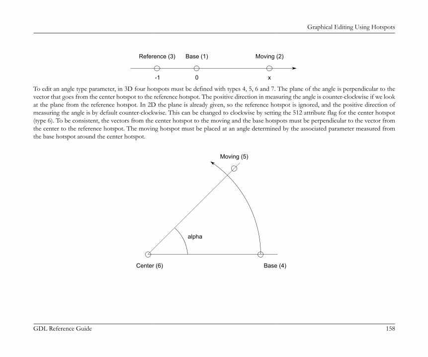
Graphical Editing Using Hotspots
GDL Reference Guide 158
Reference (3) Base (1) Moving (2)
-1 0 x
To edit an angle type parameter, in 3D four hotspots must be defined with types 4, 5, 6 and 7. The plane of the angle is perpendicular to thevector that goes from the center hotspot to the reference hotspot. The positive direction in measuring the angle is counter-clockwise if we lookat the plane from the reference hotspot. In 2D the plane is already given, so the reference hotspot is ignored, and the positive direction ofmeasuring the angle is by default counter-clockwise. This can be changed to clockwise by setting the 512 attribute flag for the center hotspot(type 6). To be consistent, the vectors from the center hotspot to the moving and the base hotspots must be perpendicular to the vector fromthe center to the reference hotspot. The moving hotspot must be placed at an angle determined by the associated parameter measured fromthe base hotspot around the center hotspot.
Center (6) Base (4)
Moving (5)
alpha
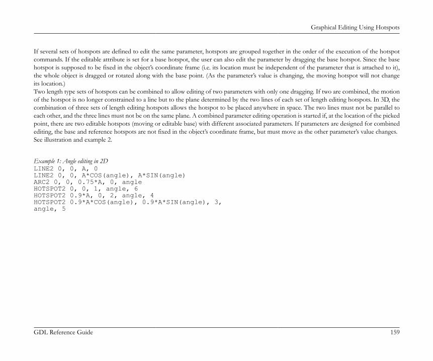
Graphical Editing Using Hotspots
GDL Reference Guide 159
If several sets of hotspots are defined to edit the same parameter, hotspots are grouped together in the order of the execution of the hotspotcommands. If the editable attribute is set for a base hotspot, the user can also edit the parameter by dragging the base hotspot. Since the basehotspot is supposed to be fixed in the object’s coordinate frame (i.e. its location must be independent of the parameter that is attached to it),the whole object is dragged or rotated along with the base point. (As the parameter’s value is changing, the moving hotspot will not changeits location.)Two length type sets of hotspots can be combined to allow editing of two parameters with only one dragging. If two are combined, the motionof the hotspot is no longer constrained to a line but to the plane determined by the two lines of each set of length editing hotspots. In 3D, thecombination of three sets of length editing hotspots allows the hotspot to be placed anywhere in space. The two lines must not be parallel toeach other, and the three lines must not be on the same plane. A combined parameter editing operation is started if, at the location of the pickedpoint, there are two editable hotspots (moving or editable base) with different associated parameters. If parameters are designed for combinedediting, the base and reference hotspots are not fixed in the object’s coordinate frame, but must move as the other parameter’s value changes.See illustration and example 2.
Example 1: Angle editing in 2DLINE2 0, 0, A, 0LINE2 0, 0, A*COS(angle), A*SIN(angle)ARC2 0, 0, 0.75*A, 0, angleHOTSPOT2 0, 0, 1, angle, 6HOTSPOT2 0.9*A, 0, 2, angle, 4HOTSPOT2 0.9*A*COS(angle), 0.9*A*SIN(angle), 3,angle, 5
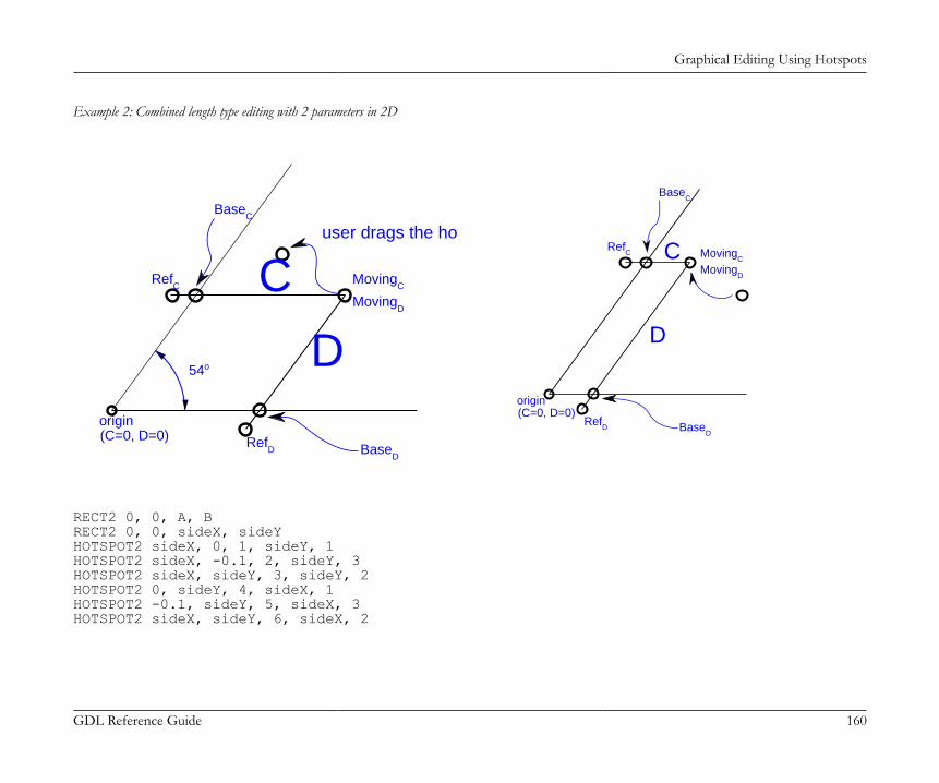
Graphical Editing Using Hotspots
GDL Reference Guide 160
Example 2: Combined length type editing with 2 parameters in 2D
54o
origin(C=0, D=0) Ref
D BaseD
MovingD
MovingC
BaseC
RefC
user drags the hotspot here
C
Dorigin(C=0, D=0)
BaseC
RefC
MovingD
MovingCC
D
RefD Base
D
RECT2 0, 0, A, BRECT2 0, 0, sideX, sideYHOTSPOT2 sideX, 0, 1, sideY, 1HOTSPOT2 sideX, -0.1, 2, sideY, 3HOTSPOT2 sideX, sideY, 3, sideY, 2HOTSPOT2 0, sideY, 4, sideX, 1HOTSPOT2 -0.1, sideY, 5, sideX, 3HOTSPOT2 sideX, sideY, 6, sideX, 2
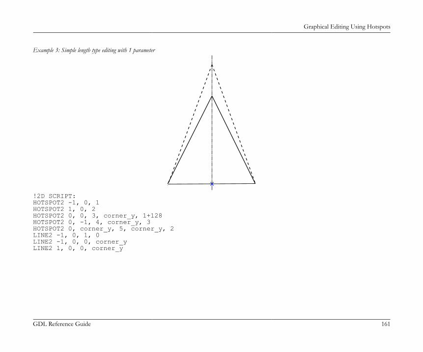
Graphical Editing Using Hotspots
GDL Reference Guide 161
Example 3: Simple length type editing with 1 parameter
!2D SCRIPT:HOTSPOT2 -1, 0, 1HOTSPOT2 1, 0, 2HOTSPOT2 0, 0, 3, corner_y, 1+128HOTSPOT2 0, -1, 4, corner_y, 3HOTSPOT2 0, corner_y, 5, corner_y, 2LINE2 -1, 0, 1, 0LINE2 -1, 0, 0, corner_yLINE2 1, 0, 0, corner_y
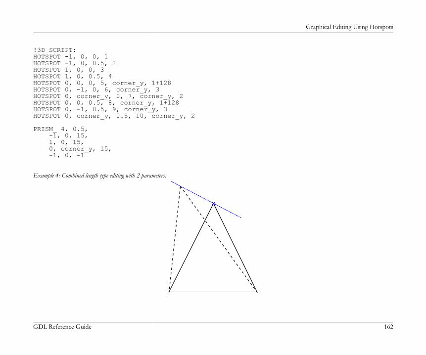
Graphical Editing Using Hotspots
GDL Reference Guide 162
!3D SCRIPT:HOTSPOT -1, 0, 0, 1HOTSPOT -1, 0, 0.5, 2HOTSPOT 1, 0, 0, 3HOTSPOT 1, 0, 0.5, 4HOTSPOT 0, 0, 0, 5, corner_y, 1+128HOTSPOT 0, -1, 0, 6, corner_y, 3HOTSPOT 0, corner_y, 0, 7, corner_y, 2HOTSPOT 0, 0, 0.5, 8, corner_y, 1+128HOTSPOT 0, -1, 0.5, 9, corner_y, 3HOTSPOT 0, corner_y, 0.5, 10, corner_y, 2
PRISM_ 4, 0.5, -1, 0, 15, 1, 0, 15, 0, corner_y, 15, -1, 0, -1
Example 4: Combined length type editing with 2 parameters:
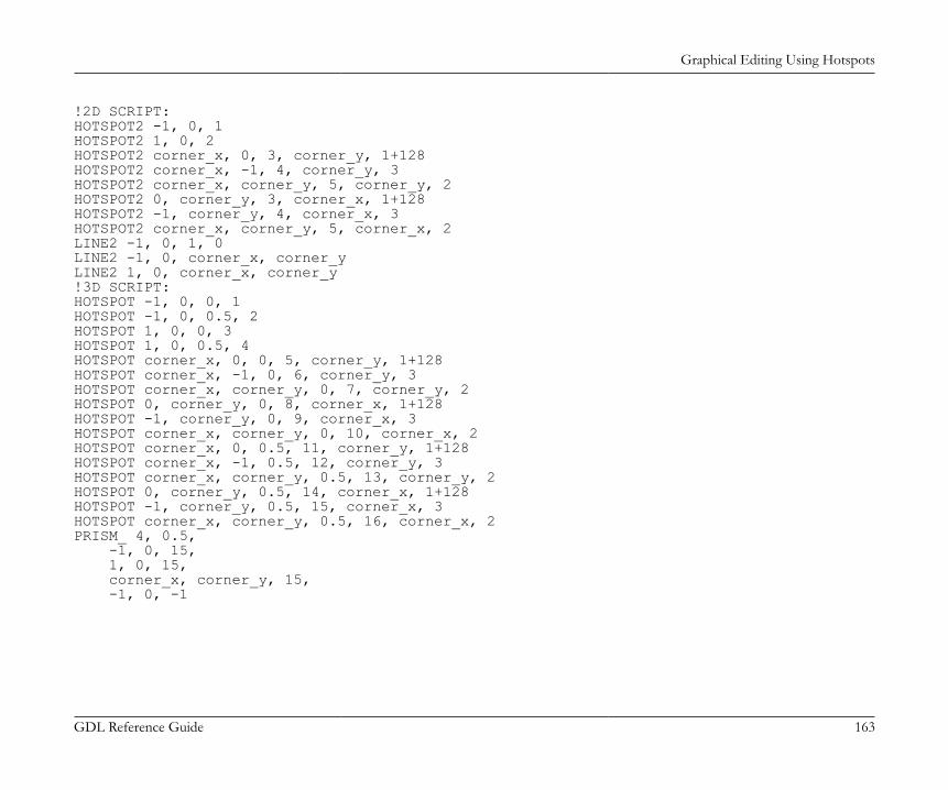
Graphical Editing Using Hotspots
GDL Reference Guide 163
!2D SCRIPT:HOTSPOT2 -1, 0, 1HOTSPOT2 1, 0, 2HOTSPOT2 corner_x, 0, 3, corner_y, 1+128HOTSPOT2 corner_x, -1, 4, corner_y, 3HOTSPOT2 corner_x, corner_y, 5, corner_y, 2HOTSPOT2 0, corner_y, 3, corner_x, 1+128HOTSPOT2 -1, corner_y, 4, corner_x, 3HOTSPOT2 corner_x, corner_y, 5, corner_x, 2LINE2 -1, 0, 1, 0LINE2 -1, 0, corner_x, corner_yLINE2 1, 0, corner_x, corner_y!3D SCRIPT:HOTSPOT -1, 0, 0, 1HOTSPOT -1, 0, 0.5, 2HOTSPOT 1, 0, 0, 3HOTSPOT 1, 0, 0.5, 4HOTSPOT corner_x, 0, 0, 5, corner_y, 1+128HOTSPOT corner_x, -1, 0, 6, corner_y, 3HOTSPOT corner_x, corner_y, 0, 7, corner_y, 2HOTSPOT 0, corner_y, 0, 8, corner_x, 1+128HOTSPOT -1, corner_y, 0, 9, corner_x, 3HOTSPOT corner_x, corner_y, 0, 10, corner_x, 2HOTSPOT corner_x, 0, 0.5, 11, corner_y, 1+128HOTSPOT corner_x, -1, 0.5, 12, corner_y, 3HOTSPOT corner_x, corner_y, 0.5, 13, corner_y, 2HOTSPOT 0, corner_y, 0.5, 14, corner_x, 1+128HOTSPOT -1, corner_y, 0.5, 15, corner_x, 3HOTSPOT corner_x, corner_y, 0.5, 16, corner_x, 2PRISM_ 4, 0.5, -1, 0, 15, 1, 0, 15, corner_x, corner_y, 15, -1, 0, -1
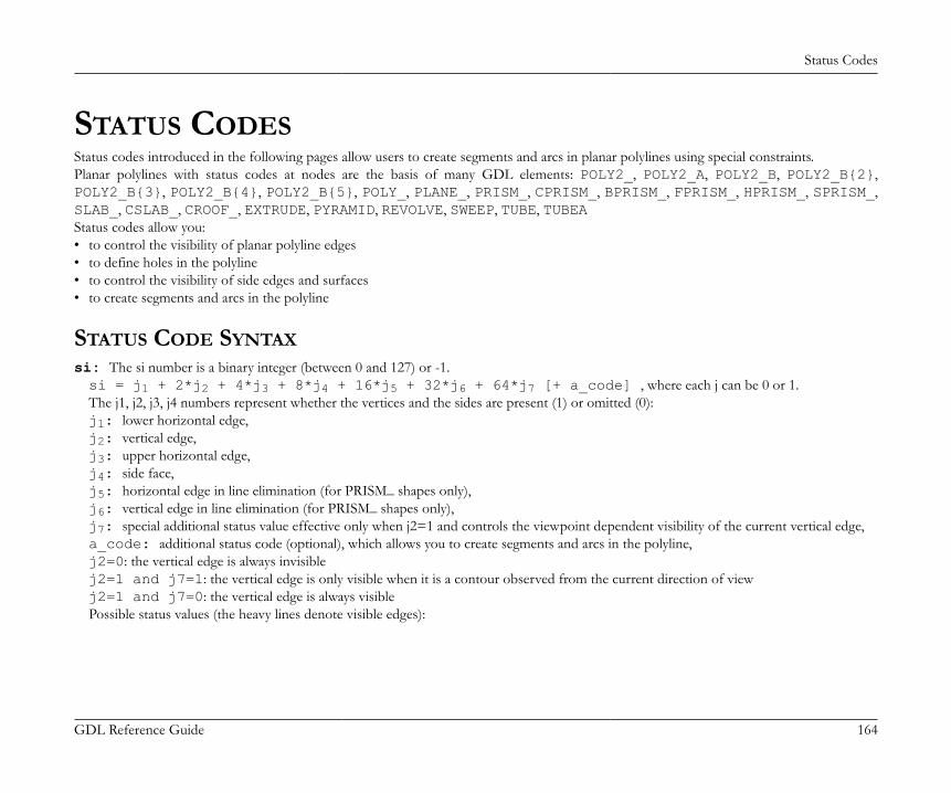
Status Codes
GDL Reference Guide 164
STATUS CODESStatus codes introduced in the following pages allow users to create segments and arcs in planar polylines using special constraints.Planar polylines with status codes at nodes are the basis of many GDL elements: POLY2_, POLY2_A, POLY2_B, POLY2_B{2},POLY2_B{3}, POLY2_B{4}, POLY2_B{5}, POLY_, PLANE_, PRISM_, CPRISM_, BPRISM_, FPRISM_, HPRISM_, SPRISM_,SLAB_, CSLAB_, CROOF_, EXTRUDE, PYRAMID, REVOLVE, SWEEP, TUBE, TUBEAStatus codes allow you:• to control the visibility of planar polyline edges• to define holes in the polyline• to control the visibility of side edges and surfaces• to create segments and arcs in the polyline
STATUS CODE SYNTAXsi: The si number is a binary integer (between 0 and 127) or -1.si = j1 + 2*j2 + 4*j3 + 8*j4 + 16*j5 + 32*j6 + 64*j7 [+ a_code] , where each j can be 0 or 1.The j1, j2, j3, j4 numbers represent whether the vertices and the sides are present (1) or omitted (0):j1: lower horizontal edge,j2: vertical edge,j3: upper horizontal edge,j4: side face,j5: horizontal edge in line elimination (for PRISM_ shapes only),j6: vertical edge in line elimination (for PRISM_ shapes only),j7: special additional status value effective only when j2=1 and controls the viewpoint dependent visibility of the current vertical edge,a_code: additional status code (optional), which allows you to create segments and arcs in the polyline,j2=0: the vertical edge is always invisiblej2=1 and j7=1: the vertical edge is only visible when it is a contour observed from the current direction of viewj2=1 and j7=0: the vertical edge is always visiblePossible status values (the heavy lines denote visible edges):
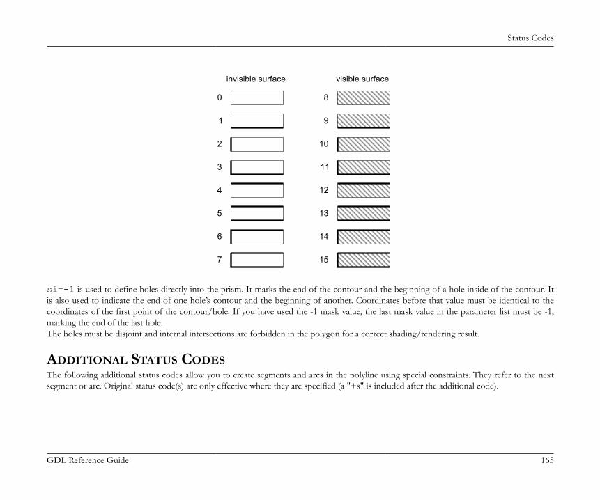
Status Codes
GDL Reference Guide 165
invisible surface visible surface
0
1
2
3
4
5
6
7
8
9
10
11
12
13
14
15
si=-1 is used to define holes directly into the prism. It marks the end of the contour and the beginning of a hole inside of the contour. Itis also used to indicate the end of one hole’s contour and the beginning of another. Coordinates before that value must be identical to thecoordinates of the first point of the contour/hole. If you have used the -1 mask value, the last mask value in the parameter list must be -1,marking the end of the last hole.The holes must be disjoint and internal intersections are forbidden in the polygon for a correct shading/rendering result.
ADDITIONAL STATUS CODESThe following additional status codes allow you to create segments and arcs in the polyline using special constraints. They refer to the nextsegment or arc. Original status code(s) are only effective where they are specified (a "+s" is included after the additional code).
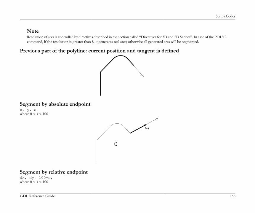
Status Codes
GDL Reference Guide 166
NoteResolution of arcs is controlled by directives described in the section called “Directives for 3D and 2D Scripts”. In case of the POLY2_command, if the resolution is greater than 8, it generates real arcs; otherwise all generated arcs will be segmented.
Previous part of the polyline: current position and tangent is defined
Segment by absolute endpointx, y, swhere 0 < s < 100
0
x,y
Segment by relative endpointdx, dy, 100+s,where 0 < s < 100
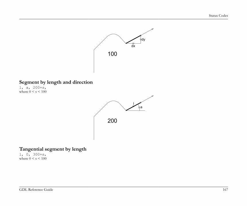
Status Codes
GDL Reference Guide 167
100dx
dy
Segment by length and directionl, a, 200+s,where 0 < s < 100
200
la
Tangential segment by lengthl, 0, 300+s,where 0 < s < 100
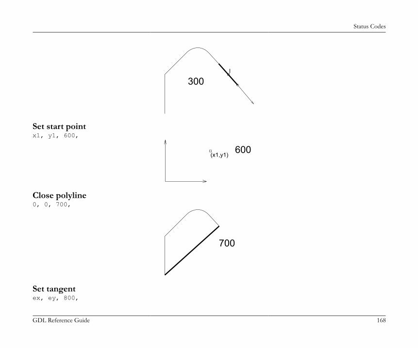
Status Codes
GDL Reference Guide 168
300l
Set start pointx1, y1, 600,
(x1,y1)600
Close polyline0, 0, 700,
700
Set tangentex, ey, 800,
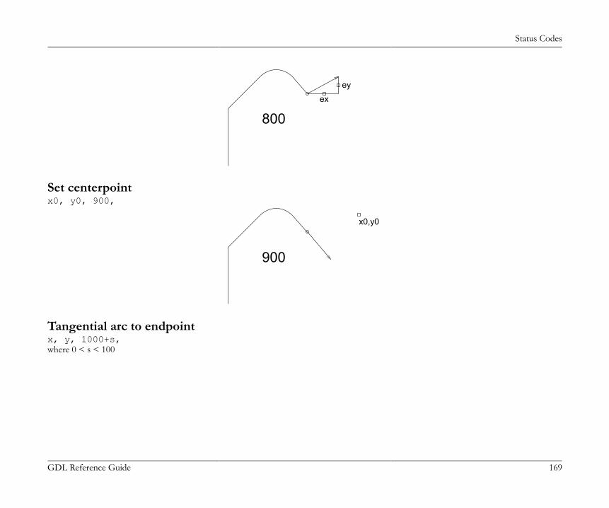
Status Codes
GDL Reference Guide 169
800ex
ey
Set centerpointx0, y0, 900,
900
x0,y0
Tangential arc to endpointx, y, 1000+s,where 0 < s < 100
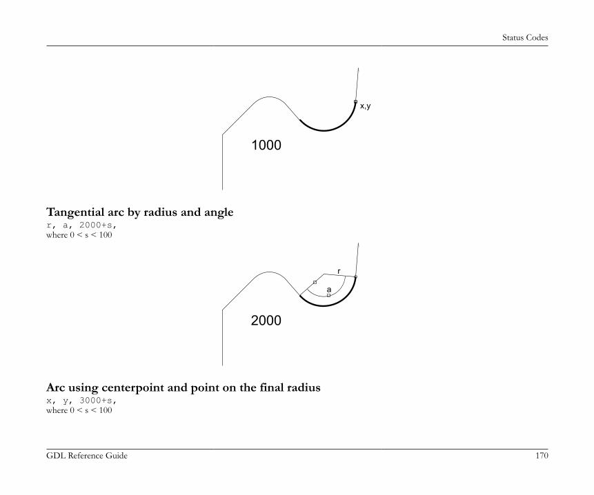
Status Codes
GDL Reference Guide 170
x,y
1000
Tangential arc by radius and angler, a, 2000+s,where 0 < s < 100
r
a
2000
Arc using centerpoint and point on the final radiusx, y, 3000+s,where 0 < s < 100
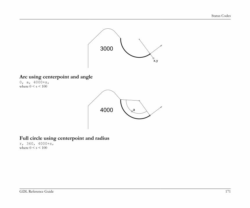
Status Codes
GDL Reference Guide 171
3000
x,y
Arc using centerpoint and angle0, a, 4000+s,where 0 < s < 100
4000 a
Full circle using centerpoint and radiusr, 360, 4000+s,where 0 < s < 100
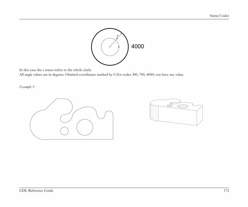
Status Codes
GDL Reference Guide 172
r
4000
In this case the s status refers to the whole circle.All angle values are in degrees. Omitted coordinates marked by 0 (for codes 300, 700, 4000) can have any value.
Example 1:
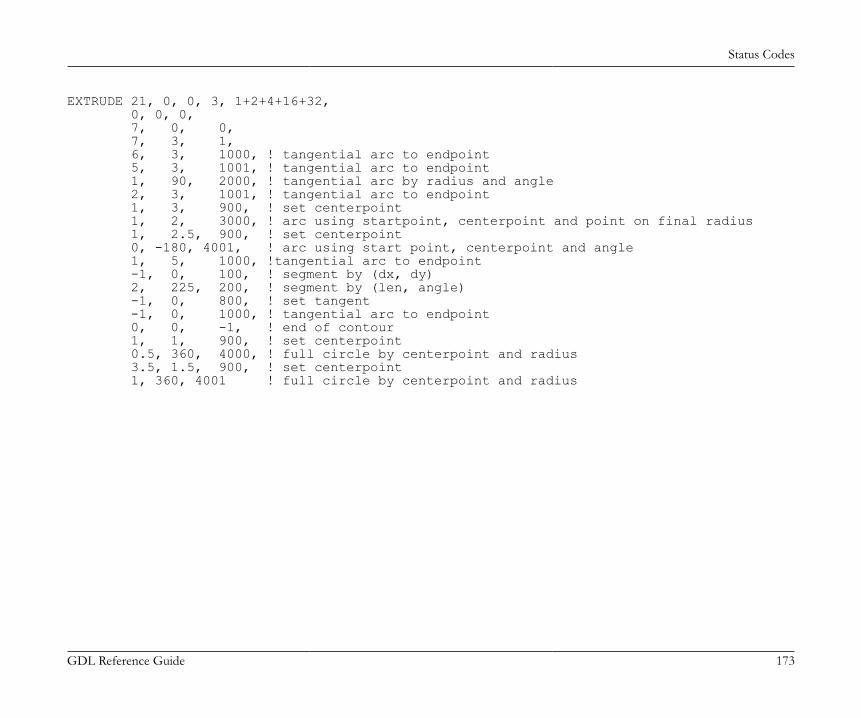
Status Codes
GDL Reference Guide 173
EXTRUDE 21, 0, 0, 3, 1+2+4+16+32, 0, 0, 0, 7, 0, 0, 7, 3, 1, 6, 3, 1000, ! tangential arc to endpoint 5, 3, 1001, ! tangential arc to endpoint 1, 90, 2000, ! tangential arc by radius and angle 2, 3, 1001, ! tangential arc to endpoint 1, 3, 900, ! set centerpoint 1, 2, 3000, ! arc using startpoint, centerpoint and point on final radius 1, 2.5, 900, ! set centerpoint 0, -180, 4001, ! arc using start point, centerpoint and angle 1, 5, 1000, !tangential arc to endpoint -1, 0, 100, ! segment by (dx, dy) 2, 225, 200, ! segment by (len, angle) -1, 0, 800, ! set tangent -1, 0, 1000, ! tangential arc to endpoint 0, 0, -1, ! end of contour 1, 1, 900, ! set centerpoint 0.5, 360, 4000, ! full circle by centerpoint and radius 3.5, 1.5, 900, ! set centerpoint 1, 360, 4001 ! full circle by centerpoint and radius
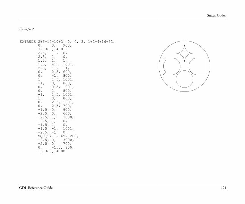
Status Codes
GDL Reference Guide 174
Example 2:
EXTRUDE 2+5+10+10+2, 0, 0, 3, 1+2+4+16+32, 0, 0, 900, 3, 360, 4001, 2.5, -1, 0, 2.5, 1, 0, 1.5, 1, 1, 1.5, -1, 1001, 2.5, -1, -1, 0, 2.5, 600, 0, -1, 800, 1, 1.5, 1001, -1, 0, 800, 0, 0.5, 1001, 0, 1, 800, -1, 1.5, 1001, 1, 0, 800, 0, 2.5, 1001, 0, 2.5, 700, -1.5, 0, 900, -2.5, 0, 600, -2.5, 1, 3000, -2.5, 1, 0, -1.5, 1, 0, -1.5, -1, 1001, -2.5, -1, 0, SQR(2)-1, 45, 200, -2.5, 0, 3000, -2.5, 0, 700, 0, -1.5, 900, 1, 360, 4000
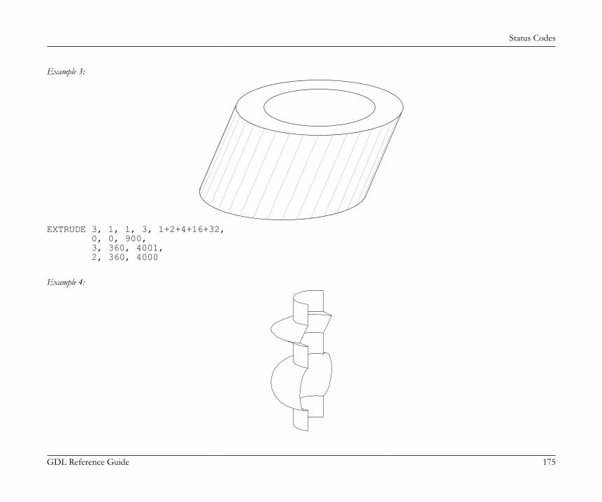
Status Codes
GDL Reference Guide 175
Example 3:
EXTRUDE 3, 1, 1, 3, 1+2+4+16+32, 0, 0, 900, 3, 360, 4001, 2, 360, 4000
Example 4:
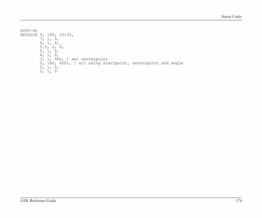
Status Codes
GDL Reference Guide 176
ROTY-90REVOLVE 9, 180, 16+32, 7, 1, 0, 6, 1, 0, 5.5, 2, 0, 5, 1, 0, 4, 1, 0, 3, 1, 900, ! set centerpoint 0, 180, 4001, ! arc using startpoint, centerpoint and angle 2, 1, 0, 1, 1, 0
Attributes
GDL Reference Guide 177
ATTRIBUTESIn the first part of this chapter, directives influencing the interpretation of GDL statements are presented. Directives may define the smoothnessused for cylindrical elements, representation mode in the 3D view or the assignment of an attribute (color, material, text style, etc.) for thesubsequent shapes. Inline attribute definition is covered in the second part. This feature allows you to assign to your objects customized materials,textures, fill patterns, line types and text styles that are not present in the current attribute set of your project.
DIRECTIVESThe influence of directives on the interpretation of the subsequent GDL statements remains in effect until the next directive or the end of thescript. Called scripts inherit the current settings: the changes have local influence. Returning from the script resets the settings as they werebefore the macro call.
Directives for 3D and 2D ScriptsLET[LET] varnam = nValue assignment. The LET directive is optional. The variable will store the evaluated value of n.
RADIUSRADIUS radius_min, radius_maxSets smoothness for cylindrical elements and arcs in polylines.A circle with a radius of r is represented:• if r < radius_min, by a hexagon,• if r >= radius_max, by a 36-edged polygon,• if radius_min < r < radius_max, by a polygon of (6+30*(r-radius_min)/(radius_max-radius_min)) edges.Arc conversion is proportional to this.After a RADIUS statement, all previous RESOL and TOLER statements lose their effect.Restriction of parameters:r_min <= r_max
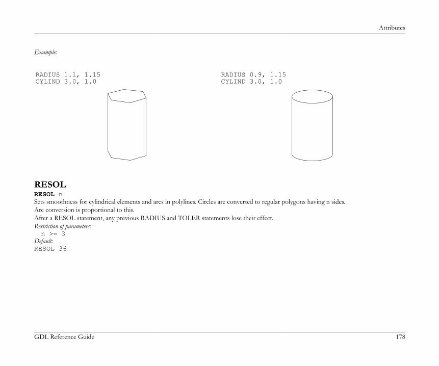
Attributes
GDL Reference Guide 178
Example:
RADIUS 1.1, 1.15CYLIND 3.0, 1.0
RADIUS 0.9, 1.15CYLIND 3.0, 1.0
RESOLRESOL nSets smoothness for cylindrical elements and arcs in polylines. Circles are converted to regular polygons having n sides.Arc conversion is proportional to this.After a RESOL statement, any previous RADIUS and TOLER statements lose their effect.Restriction of parameters:n >= 3
Default:RESOL 36
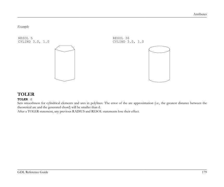
Attributes
GDL Reference Guide 179
Example:
RESOL 5CYLIND 3.0, 1.0
RESOL 36CYLIND 3.0, 1.0
TOLERTOLER dSets smoothness for cylindrical elements and arcs in polylines. The error of the arc approximation (i.e., the greatest distance between thetheoretical arc and the generated chord) will be smaller than d.After a TOLER statement, any previous RADIUS and RESOL statements lose their effect.
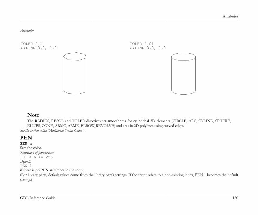
Attributes
GDL Reference Guide 180
Example:
TOLER 0.1CYLIND 3.0, 1.0
TOLER 0.01CYLIND 3.0, 1.0
NoteThe RADIUS, RESOL and TOLER directives set smoothness for cylindrical 3D elements (CIRCLE, ARC, CYLIND, SPHERE,ELLIPS, CONE, ARMC, ARME, ELBOW, REVOLVE) and arcs in 2D polylines using curved edges.
See the section called “Additional Status Codes”.
PENPEN nSets the color.Restriction of parameters:0 < n <= 255
Default:PEN 1if there is no PEN statement in the script.(For library parts, default values come from the library part’s settings. If the script refers to a non-existing index, PEN 1 becomes the defaultsetting.)
Attributes
GDL Reference Guide 181
LINE_PROPERTYLINE_PROPERTY exprDefines the property for all subsequently generated lines in the 2D script (RECT2, LINE2, ARC2, CIRCLE2, SPLINE2, SPLINE2A, POLY2,FRAGMENT2commands) until the next LINE_PROPERTY statement. Default value is generic.expr: possible values:0: all lines are generic lines,1: all lines are inner,2: all lines are contour.
[SET] STYLE[SET] STYLE name_string[SET] STYLE indexAll the texts generated afterwards will use that style until the next SET STYLE statement.The index is a constant referring to a style stack in the internal data structure (negative indices mean indices in the data structure of materialspreviously defined in the GDL script). This stack is modified during GDL analysis and can also be modified from within the program. The useof the index instead of the style name is only recommended with the prior use of the IND function.Default:SET STYLE 0(application font, size 5 mm, anchor = 1, normal face) if there is no SET STYLE statement in the script.
Directives Used in 3D Scripts OnlyMODELMODEL WIREMODEL SURFACEMODEL SOLIDSets the representation mode in the current script.MODEL WIRE: only wireframe, no surfaces or volumes. Objects are transparent.MODEL SURFACE, MODEL SOLID: The generation of the section surfaces is based on the relation of the boundary surfaces, so that bothmethods generate the same 3D internal data structure. Objects are opaque.The only distinction can be seen after cutting away a part of the body:MODEL SURFACE: the inside of bodies will be visible,MODEL SOLID: new surfaces may appear.
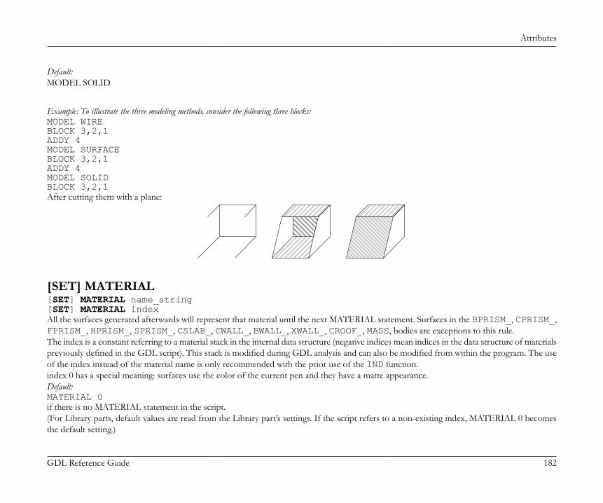
Attributes
GDL Reference Guide 182
Default:MODEL SOLID
Example: To illustrate the three modeling methods, consider the following three blocks:MODEL WIREBLOCK 3,2,1ADDY 4MODEL SURFACEBLOCK 3,2,1ADDY 4MODEL SOLIDBLOCK 3,2,1After cutting them with a plane:
[SET] MATERIAL[SET] MATERIAL name_string[SET] MATERIAL indexAll the surfaces generated afterwards will represent that material until the next MATERIAL statement. Surfaces in the BPRISM_, CPRISM_,FPRISM_, HPRISM_, SPRISM_, CSLAB_, CWALL_, BWALL_, XWALL_, CROOF_, MASS, bodies are exceptions to this rule.The index is a constant referring to a material stack in the internal data structure (negative indices mean indices in the data structure of materialspreviously defined in the GDL script). This stack is modified during GDL analysis and can also be modified from within the program. The useof the index instead of the material name is only recommended with the prior use of the IND function.index 0 has a special meaning: surfaces use the color of the current pen and they have a matte appearance.Default:MATERIAL 0if there is no MATERIAL statement in the script.(For Library parts, default values are read from the Library part’s settings. If the script refers to a non-existing index, MATERIAL 0 becomesthe default setting.)
Attributes
GDL Reference Guide 183
SECT_FILLSECT_FILL fill, fill_background_pen, fill_pen, contour_penor
SECT_ATTRSSECT_ATTRS fill, fill_background_pen, fill_pen, contour_pen [, line_type]Defines the attributes used for the cut part of the 3D elements in the Section/Elevation window and the PROJECT2{3} command (forcompatibility reasons previous versions of the PROJECT2 command are not affected).fill: fill name or index number.fill_background_pen: fill background pencolor number.fill_pen: fill pencolor number.contour_pen: fill contour pencolor number.line_type: line type of polygon edges.
SHADOWSHADOW casting [, catching]Controls the shadow casting of the elements in PhotoRendering and in vectorial shadow casting.casting: ON, AUTO or OFFON: all the subsequent elements will cast shadows in all circumstances,OFF: none of the subsequent elements will cast shadows in any circumstance,AUTO: shadow casting will be determined automaticallySetting SHADOW OFF for hidden parts will spare memory space and processing time.Setting SHADOW ON ensures that even tiny details will cast shadows.
catching: ON or OFFThis optional parameter controls the appearance of shadows (from other bodies) on surfaces.
If shadow casting isn't specified, the default will be AUTO.
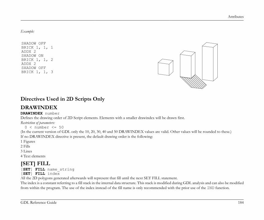
Attributes
GDL Reference Guide 184
Example:
SHADOW OFFBRICK 1, 1, 1ADDX 2SHADOW ONBRICK 1, 1, 2ADDX 2SHADOW OFFBRICK 1, 1, 3
Directives Used in 2D Scripts OnlyDRAWINDEXDRAWINDEX numberDefines the drawing order of 2D Script elements. Elements with a smaller drawindex will be drawn first.Restriction of parameters:0 < number <= 50
(In the current version of GDL only the 10, 20, 30, 40 and 50 DRAWINDEX values are valid. Other values will be rounded to these.)If no DRAWINDEX directive is present, the default drawing order is the following:1 Figures2 Fills3 Lines4 Text elements
[SET] FILL[SET] FILL name_string[SET] FILL indexAll the 2D polygons generated afterwards will represent that fill until the next SET FILL statement.The index is a constant referring to a fill stack in the internal data structure. This stack is modified during GDL analysis and can also be modifiedfrom within the program. The use of the index instead of the fill name is only recommended with the prior use of the IND function.
Attributes
GDL Reference Guide 185
Default:SET FILL 0i.e., empty fill, if there is no SET FILL statement in the script.
[SET] LINE_TYPE[SET] LINE_TYPE name_string[SET] LINE_TYPE indexAll the 2D lines generated afterwards will represent that line type (in lines, arcs, polylines) until the next SET LINE_TYPE statement. Theindex is a constant that refers to a line type stack in the internal data structure. This stack is modified during GDL analysis and can also bemodified from the program. The use of the index instead of the line type name is only recommended with the prior use of the IND function.Default:SET LINE_TYPE 1i. e., solid line, if there is no SET LINE_TYPE statement in the script.
INLINE ATTRIBUTE DEFINITIONAttributes in can be created using the material, fill and line type dialog boxes. These floor plan attributes can be referenced from any GDLscript. Attributes can also be defined in GDL scripts. There are two different cases:• Attribute definition in the MASTER_GDL script. The MASTER_GDL script is interpreted when the library that contains it is loaded in the
memory. The MASTER_GDL attributes are merged into the floor plan attributes; attributes with the same names are not replaced. Oncethe MASTER_GDL is loaded, the attributes defined in it can be referenced from any script.
• Attribute definition in library parts. The materials and textures defined this way can be used in the script and its second generation scripts.Fills and line types defined and used in the 2D script have the same behavior as if they were defined in the MASTER_GDL script.
The Check GDL Script command in the script window helps to verify whether the material, fill, line type or style parameters are correct.When a material, fill, line type or style is different in the 3D interpretation of the library part from the intended one, but there is no errormessage, this probably means that one or more of the parameter values are incorrect. The Check GDL Scripts command will help you withdetailed messages to find these parameters.
Attributes
GDL Reference Guide 186
MaterialsDEFINE MATERIALDEFINE MATERIAL name type, surface_red, surface_green, surface_blue [, ambient_ce, diffuse_ce, specular_ce, transparent_ce, shining, transparency_attenuation [, specular_red, specular_green, specular_blue, emission_red, emission_green, emission_blue, emission_att]] [, fill_index [, fillcolor_index, texture_index]]
Note: This command can contain additional data definition.See the section called “Additional Data” for details.Any GDL script can include material definitions prior to the first reference to that material name. This material can only be used for 3Delements in its own script and its second generation scripts.name: name of the material.type: type of the material. The actual number (n) of parameters that define the material is different, depending on the type. The meaning
of the parameters and their limits are explained in the examples’ comments.0: general definition, n=16,1: simple definition, n=9 (extra parameters are constants or calculated from given values),2-7: predefined material types, n=3. The three values are the RGB components of the surface color. Other parameters are constantsor calculated from the color.2: matte,3: metal,4: plastic,5: glass,6: glowing,7: constant,10: general definition with fill parameter, n=17,11: simple definition with fill parameter, n=10,12-17: predefined material types with fill parameter, n=4,20: general definition with fill, color index of fill and index of texture parameters, n=19,21: simple definition with fill, color index of fill and index of texture parameters, n=12,22-27: predefined material types with fill, color index of fill and index of texture parameters, n=6.
Attributes
GDL Reference Guide 187
20-27: Special meanings for types 20-27: If the pen number is zero, vectorial hatches will be generated with the active pen. Zero valuefor a texture or fill index allows you to define materials without a vectorial hatch or texture.
Example 1: Materials with solid colorsDEFINE MATERIAL "water" 0, 0.5284, 0.5989, 0.6167,! surface RGB [0.0..1.0] 1.0, ! ambient coefficient [0.0..1.0] 0.5, ! diffuse coefficient [0.0..1.0] 0.5, ! specular coeff. [0.0..1.0] 0.9, ! transparent coeff. [0.0..1.0] 2.0, ! shining [0.0..100.0] 1, ! transparency atten. [0.0..4.0] 0.5284, 0.5989, 0.6167,! specular RGB [0.0..1.0] 0, 0, 0, ! emission RGB [0.0..1.0] 0.0 ! emission atten. [0.0..65.5]DEFINE MATERIAL "asphalt" 1, 0.1995, 0.2023, 0.2418,! surface RGB [0.0..1.0] 1.0, 1.0, 0.0, 0.0, ! ambient, diffuse, specular, transparent ! coefficients [0.0..1.0] 0, ! shining [0..100] 0 ! transparency attenuation [0..4]DEFINE MATERIAL "matte red" 2, 1.0, 0.0, 0.0 ! surface RGB [0.0..1.0]
Example 2: Material with fillDEFINE MATERIAL "Brick-Red" 10, 0.878294, 0.398199, 0.109468, 0.58, 0.85, 0.0, 0.0, 0, 0.0, 0.878401, 0.513481, 0.412253, 0.0, 0.0, 0.0, 0, IND(FILL, "common brick") ! fill index
Attributes
GDL Reference Guide 188
Example 3: Material with fill and textureDEFINE MATERIAL "Yellow Brick+*" 20, 1, 1, 0, ! surface RGB [0.0 .. 1.0] 0.58, 0.85, 0, 0, ! ambient, diffuse, specular, transparent ! coefficients [0.0 .. 1.0] 0, ! shining [0.0 .. 100.0] 0, ! transparency attenuation [0.0 .. 4.0] 0.878401, 0.513481, 0.412253, ! specular RGB [0.0 .. 1.0] 0, 0, 0, ! emission RGB [0.0 .. 1.0] 0, ! emission attenuation [0.0 .. 65.5] IND(FILL, "common brick"), 61, IND(TEXTURE, "Brick") ! Fill index, color index, texture index
DEFINE MATERIAL BASED_ONDEFINE MATERIAL name [,] BASED_ON orig_name [,] PARAMETERS name1 = expr1 [, ...] [[,] ADDITIONAL_DATA name1 = expr1 [, ...]]Material definition based on an existing material. Specified parameters of the original material will be overwritten by the new values, otherparameters remain untouched. Using the command without actual parameters results in a material exactly the same as the original, but with adifferent name. Parameter values of a material can be obtained using the REQUEST{2} ("Material_info", ...) function.orig_name: name of the original material (name of an existing, previously defined in GDL or floor plan material).namei: material parameter name to be overwritten by a new value. Names corresponding to parameters of material definition:gs_mat_surface_r, gs_mat_surface_g, gs_mat_surface_b: (surface RGB [0.0..1.0])gs_mat_ambient: (ambient coefficient [0.0..1.0])gs_mat_diffuse: (diffuse coefficient [0.0..1.0])gs_mat_specular: (specular coefficient [0.0..1.0])gs_mat_transparent: (transparent coefficient [0.0..1.0])gs_mat_shining: (shininess [0.0..100.0])gs_mat_transp_att: (transparency attenuation [0.0..4.0])gs_mat_specular_r, gs_mat_specular_g, gs_mat_specular_b: (specular color RGB [0.0..1.0])gs_mat_emission_r, gs_mat_emission_g, gs_mat_emission_b: (emission color RGB [0.0..1.0])gs_mat_emission_att: (emission attenuation [0.0..65.5])gs_mat_fill_ind: (fill index)gs_mat_fillcolor_ind: (fill color index)
Attributes
GDL Reference Guide 189
gs_mat_texture_ind: (texture index)expri: new value to overwrite the specified parameter of the material. Value ranges are the same as at the material definition.
Example:n = REQUEST{2} ("Material_info", "Brick-Face", "gs_mat_emission_rgb ", em_r, em_g, em_b)em_r = em_r + (1 - em_r) / 3em_g = em_g + (1 - em_g) / 3em_b = em_b + (1 - em_b) / 3DEFINE MATERIAL "Brick-Face light" [,] BASED_ON "Brick-Face" \ PARAMETERS gs_mat_emission_r = em_r, gs_mat_emission_g = em_g, gs_mat_emission_b = em_bSET MATERIAL "Brick-Face"BRICK a, b, zzyzxADDX aSET MATERIAL "Brick-Face light"BRICK a, b, zzyzx
DEFINE TEXTUREDEFINE TEXTURE name expression, x, y, mask, angleAny GDL script can include texture definition prior to the first reference to that texture name. The texture can be used only in the script inwhich it was defined and its subsequent second generation scripts.name: name of the texture.expression: picture associated with the texture. A string expression means a file name, a numerical expression an index of a picture
stored in the library part. A 0 index is a special value which refers to the preview picture of the library part.x: logical width of the texture.y: logical height of the texture.mask:mask = j1 + 2*j2 + 4*j3 + 8*j4 + 16*j5 + 32*j6 + 64*j7 + 128*j8 + 256*j9, where each j can be 0 or 1.Alpha channel controls (j1... j6):j1: alpha channel changes the transparency of texture,j2: Bump mapping or surface normal perturbation. Bump mapping uses the alpha channel to determine the amplitude of the surfacenormal,j3: alpha channel changes the diffuse color of texture,j4: alpha channel changes the specular color of texture,
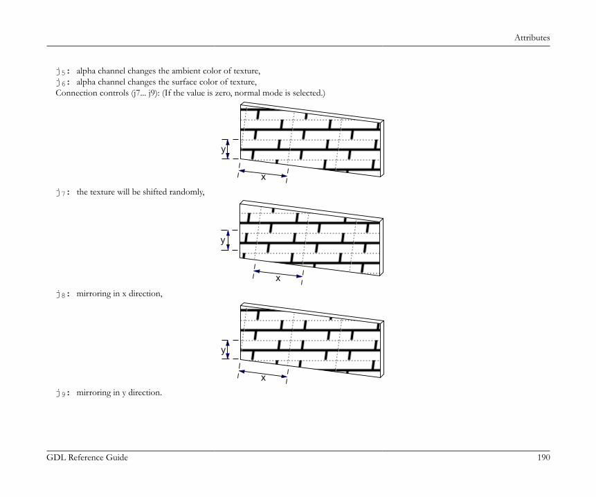
Attributes
GDL Reference Guide 190
j5: alpha channel changes the ambient color of texture,j6: alpha channel changes the surface color of texture,Connection controls (j7... j9): (If the value is zero, normal mode is selected.)
x
y
j7: the texture will be shifted randomly,
x
y
j8: mirroring in x direction,
x
y
j9: mirroring in y direction.
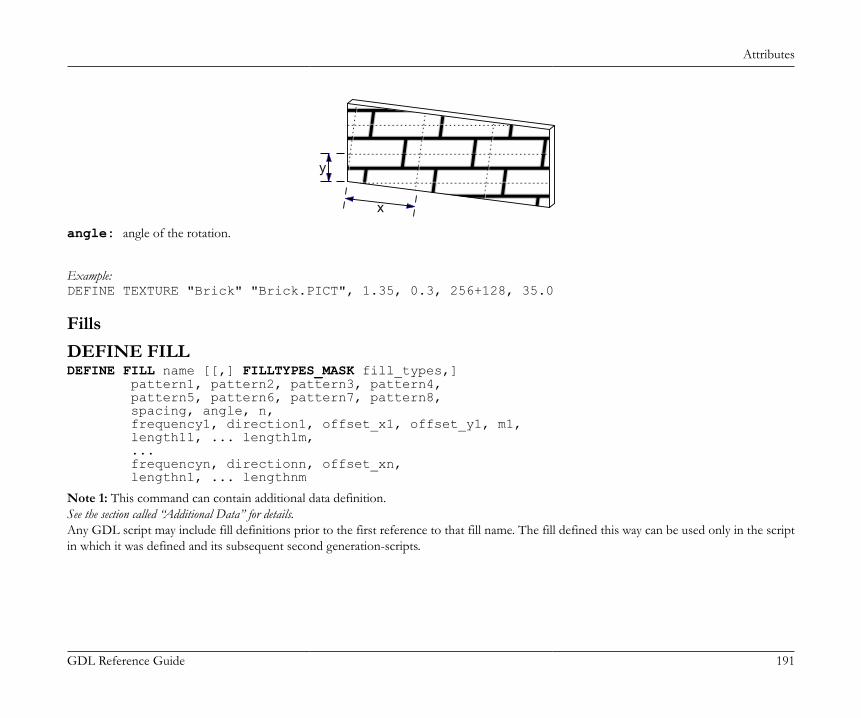
Attributes
GDL Reference Guide 191
x
y
angle: angle of the rotation.
Example:DEFINE TEXTURE "Brick" "Brick.PICT", 1.35, 0.3, 256+128, 35.0
FillsDEFINE FILLDEFINE FILL name [[,] FILLTYPES_MASK fill_types,] pattern1, pattern2, pattern3, pattern4, pattern5, pattern6, pattern7, pattern8, spacing, angle, n, frequency1, direction1, offset_x1, offset_y1, m1, length11, ... length1m, ... frequencyn, directionn, offset_xn, lengthn1, ... lengthnm
Note 1: This command can contain additional data definition.See the section called “Additional Data” for details.Any GDL script may include fill definitions prior to the first reference to that fill name. The fill defined this way can be used only in the scriptin which it was defined and its subsequent second generation-scripts.
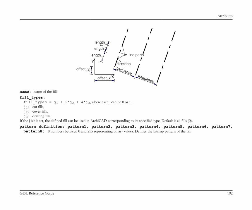
Attributes
GDL Reference Guide 192
frequencyi frequency
i
offset_yi
offset_xi
lengthi1
lengthi2
lengthim...
m line parts
directioni
X
Y
name: name of the fill.fill_types:fill_types = j1 + 2*j2 + 4*j3, where each j can be 0 or 1.j1: cut fills,j2: cover fills,j3: drafting fills.
If the j bit is set, the defined fill can be used in ArchiCAD corresponding to its specified type. Default is all fills (0).pattern definition: pattern1, pattern2, pattern3, pattern4, pattern5, pattern6, pattern7,pattern8: 8 numbers between 0 and 255 representing binary values. Defines the bitmap pattern of the fill.
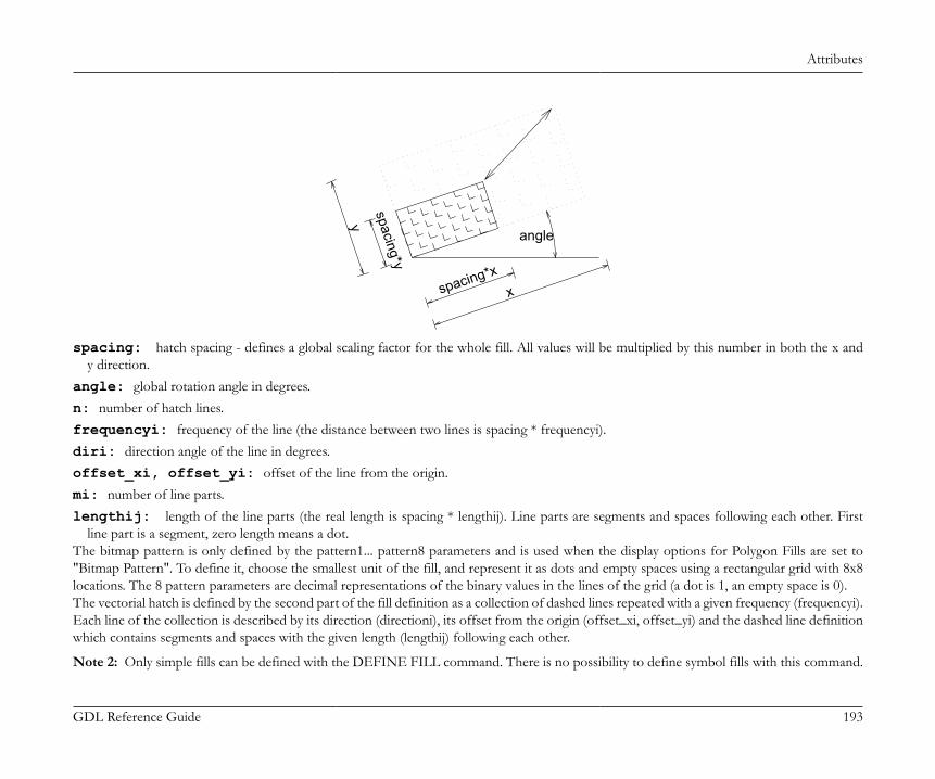
Attributes
GDL Reference Guide 193
y
x
spacing*y
spacing*x
angle
spacing: hatch spacing - defines a global scaling factor for the whole fill. All values will be multiplied by this number in both the x andy direction.
angle: global rotation angle in degrees.n: number of hatch lines.frequencyi: frequency of the line (the distance between two lines is spacing * frequencyi).diri: direction angle of the line in degrees.offset_xi, offset_yi: offset of the line from the origin.mi: number of line parts.lengthij: length of the line parts (the real length is spacing * lengthij). Line parts are segments and spaces following each other. First
line part is a segment, zero length means a dot.The bitmap pattern is only defined by the pattern1... pattern8 parameters and is used when the display options for Polygon Fills are set to"Bitmap Pattern". To define it, choose the smallest unit of the fill, and represent it as dots and empty spaces using a rectangular grid with 8x8locations. The 8 pattern parameters are decimal representations of the binary values in the lines of the grid (a dot is 1, an empty space is 0).The vectorial hatch is defined by the second part of the fill definition as a collection of dashed lines repeated with a given frequency (frequencyi).Each line of the collection is described by its direction (directioni), its offset from the origin (offset_xi, offset_yi) and the dashed line definitionwhich contains segments and spaces with the given length (lengthij) following each other.
Note 2: Only simple fills can be defined with the DEFINE FILL command. There is no possibility to define symbol fills with this command.
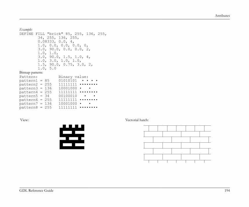
Attributes
GDL Reference Guide 194
Example:DEFINE FILL "brick" 85, 255, 136, 255, 34, 255, 136, 255, 0.08333, 0.0, 4, 1.0, 0.0, 0.0, 0.0, 0, 3.0, 90.0, 0.0, 0.0, 2, 1.0, 1.0, 3.0, 90.0, 1.5, 1.0, 4, 1.0, 3.0, 1.0, 1.0, 1.5, 90.0, 0.75, 3.0, 2, 1.0, 5.0Bitmap pattern:Pattern: Binary value:pattern1 = 85 01010101 • • • •pattern2 = 255 11111111 ••••••••pattern3 = 136 10001000 • •pattern4 = 255 11111111 ••••••••pattern5 = 34 00100010 • •pattern6 = 255 11111111 ••••••••pattern7 = 136 10001000 • •pattern8 = 255 11111111 ••••••••
View: Vectorial hatch:
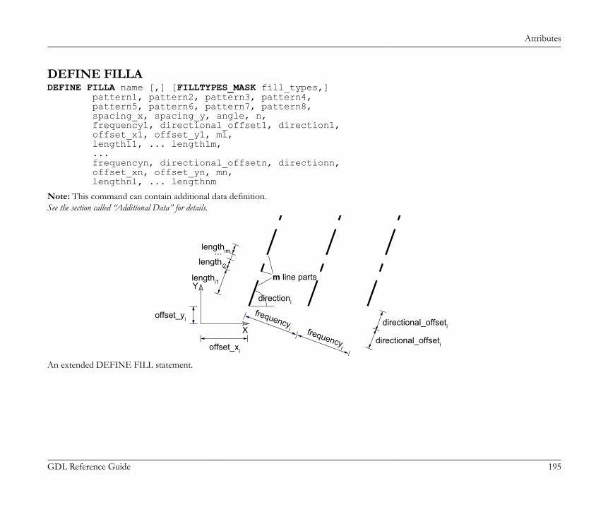
Attributes
GDL Reference Guide 195
DEFINE FILLADEFINE FILLA name [,] [FILLTYPES_MASK fill_types,] pattern1, pattern2, pattern3, pattern4, pattern5, pattern6, pattern7, pattern8, spacing_x, spacing_y, angle, n, frequency1, directional_offset1, direction1, offset_x1, offset_y1, m1, length11, ... length1m, ... frequencyn, directional_offsetn, directionn, offset_xn, offset_yn, mn, lengthn1, ... lengthnm
Note: This command can contain additional data definition.See the section called “Additional Data” for details.
X
Y
directional_offseti
directional_offseti
lengthi1
lengthi2
lengthim...
frequencyi frequency
i
offset_yi
offset_xi
directioni
m line parts
An extended DEFINE FILL statement.
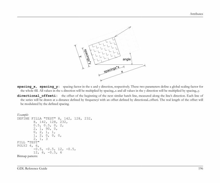
Attributes
GDL Reference Guide 196
xspacingx*x
spacingy*y
y
angle
spacing_x, spacing_y: spacing factor in the x and y direction, respectively. These two parameters define a global scaling factor forthe whole fill. All values in the x direction will be multiplied by spacing_x and all values in the y direction will be multiplied by spacing_y.
directional_offseti: the offset of the beginning of the next similar hatch line, measured along the line’s direction. Each line ofthe series will be drawn at a distance defined by frequencyi with an offset defined by directional_offseti. The real length of the offset willbe modulated by the defined spacing.
Example:DEFINE FILLA "TEST" 8, 142, 128, 232, 8, 142, 128, 232, 0.5, 0.5, 0, 2, 2, 1, 90, 0, 0, 2, 1, 1, 1, 2, 0, 0, 0, 2, 1, 3FILL "TEST"POLY2 4, 6, -0.5, -0.5, 12, -0.5, 12, 6, -0.5, 6Bitmap pattern:
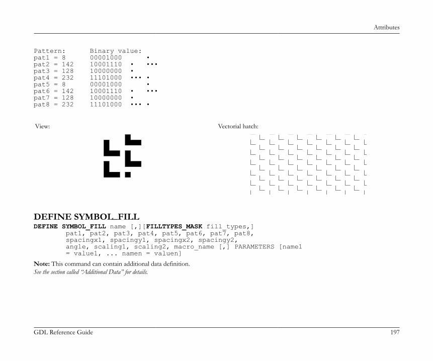
Attributes
GDL Reference Guide 197
Pattern: Binary value:pat1 = 8 00001000 •pat2 = 142 10001110 • •••pat3 = 128 10000000 •pat4 = 232 11101000 ••• •pat5 = 8 00001000 •pat6 = 142 10001110 • •••pat7 = 128 10000000 •pat8 = 232 11101000 ••• •
View: Vectorial hatch:
DEFINE SYMBOL_FILLDEFINE SYMBOL_FILL name [,][FILLTYPES_MASK fill_types,] pat1, pat2, pat3, pat4, pat5, pat6, pat7, pat8, spacingx1, spacingy1, spacingx2, spacingy2, angle, scaling1, scaling2, macro_name [,] PARAMETERS [name1 = value1, ... namen = valuen]
Note: This command can contain additional data definition.See the section called “Additional Data” for details.
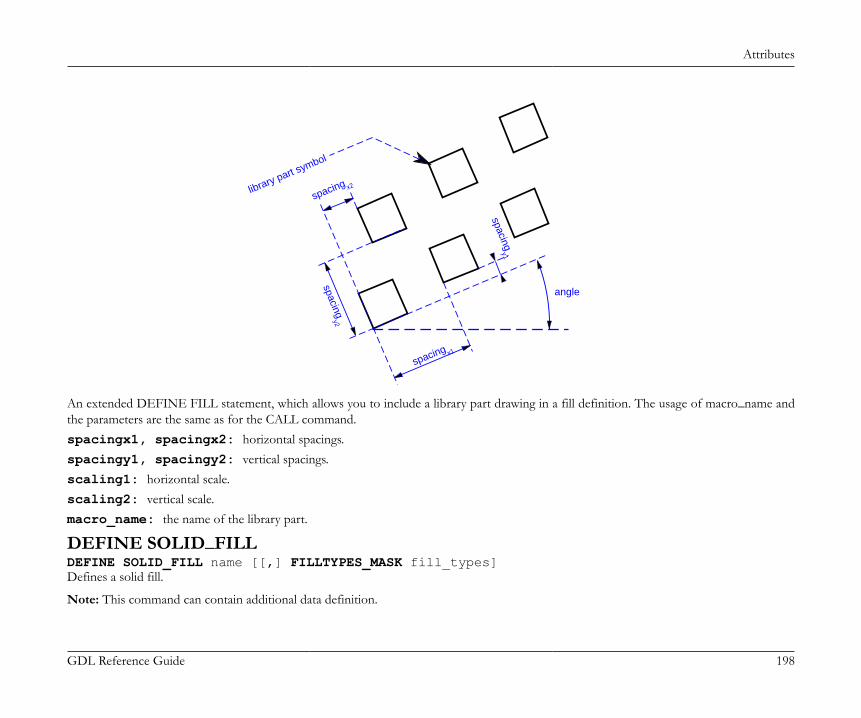
Attributes
GDL Reference Guide 198
spacing x2
spacing x1
spacingy2
spacingy1
library part symbol
angle
An extended DEFINE FILL statement, which allows you to include a library part drawing in a fill definition. The usage of macro_name andthe parameters are the same as for the CALL command.spacingx1, spacingx2: horizontal spacings.spacingy1, spacingy2: vertical spacings.scaling1: horizontal scale.scaling2: vertical scale.macro_name: the name of the library part.
DEFINE SOLID_FILLDEFINE SOLID_FILL name [[,] FILLTYPES_MASK fill_types]Defines a solid fill.
Note: This command can contain additional data definition.
Attributes
GDL Reference Guide 199
See the section called “Additional Data” for details.
DEFINE EMPTY_FILLDEFINE EMPTY_FILL name [[,] FILLTYPES_MASK fill_types]Defines an empty fill.
Note: This command can contain additional data definition.See the section called “Additional Data” for details.
DEFINE LINEAR_GRADIENT_FILLDEFINE LINEAR_GRADIENT_FILL name [[,] FILLTYPES_MASK fill_types]Define linear gradient fill.
DEFINE RADIAL_GRADIENT_FILLDEFINE RADIAL_GRADIENT_FILL name [[,] FILLTYPES_MASK fill_types]Define radial gradient fill.
DEFINE TRANSLUCENT_FILLDEFINE TRANSLUCENT_FILL name [[,] FILLTYPES_MASK fill_types] pat1, pat2, pat3, pat4, pat5, pat6, pat7, pat8, percentageDefine a fill, which shows the background and foreground colors in mixture defined by the given percentage value.percentage: percentage of foreground color opacity; 0 displays background color only (like empty fill), 100 displays the foreground
color only (like solid fill).
DEFINE IMAGE_FILLDEFINE IMAGE_FILL name image_name [[,] FILLTYPES_MASK fill_types] part1, part2, part3, part4, part5, part6, part7, part8, image_vert_size, image_hor_size, image_mask, image_rotangleDefine a fill based on an image pattern.image_name: name of the pattern image loaded in the current library.image_vert_size, image_hor_size: model size of the pattern.image_mask: tiling directiveimage_mask = 1024*j11 + 2048*j12, where each j can be 0 or 1.For more information about laying out images on a surface see the DEFINE TEXTURE command.
Attributes
GDL Reference Guide 200
j11: mirroring in x directionj12: mirroring in y direction
image_rotangle: rotation angle of the pattern from the normal coordinate system.
Line TypesDEFINE LINE_TYPEDEFINE LINE_TYPE name spacing, n, length1, ... lengthn
Note 1: This command can contain additional data definition.See the section called “Additional Data” for details.Any GDL script may include line type definitions prior to the first reference to that line-type name. The line type defined this way can be usedonly for 2D elements in the script in which it was defined and its subsequent second generation scripts.name: name of the line type.spacing: spacing factor.n: number of the line parts.lengthi: length of the line parts (the real length is spacing * lengthi). Line parts consist of segments and spaces. First line part is a segment,
zero length means a dot.
Note 2: Only simple line types - i.e. consisting only of segments and spaces - can be defined with this command, defining symbol line typescan be done with the DEFINE SYMBOL_LINE command.
Example:DEFINE LINE_TYPE "line - - ." 1, 6, 0.005, 0.002, 0.001, 0.002, 0.0, 0.002
DEFINE SYMBOL_LINEDEFINE SYMBOL_LINE name dash, gap, macro_name PARAMETERS [name1 = value1, ... namen = valuen]
Note: This command can contain additional data definition.See the section called “Additional Data” for details.
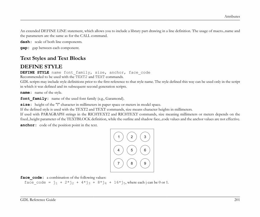
Attributes
GDL Reference Guide 201
An extended DEFINE LINE statement, which allows you to include a library part drawing in a line definition. The usage of macro_name andthe parameters are the same as for the CALL command.dash: scale of both line components.gap: gap between each component.
Text Styles and Text BlocksDEFINE STYLEDEFINE STYLE name font_family, size, anchor, face_codeRecommended to be used with the TEXT2 and TEXT commands.GDL scripts may include style definitions prior to the first reference to that style name. The style defined this way can be used only in the scriptin which it was defined and its subsequent second generation scripts.name: name of the style.font_family: name of the used font family (e.g., Garamond).size: height of the "l" character in millimeters in paper space or meters in model space.If the defined style is used with the TEXT2 and TEXT commands, size means character heights in millimeters.If used with PARAGRAPH strings in the RICHTEXT2 and RICHTEXT commands, size meaning millimeters or meters depends on thefixed_height parameter of the TEXTBLOCK definition, while the outline and shadow face_code values and the anchor values are not effective.anchor: code of the position point in the text.
1 2 3
4 5 6
7 8 9
face_code: a combination of the following values:face_code = j1 + 2*j2 + 4*j3 + 8*j4 + 16*j5, where each j can be 0 or 1.
Attributes
GDL Reference Guide 202
j1: bold,j2: italic,j3: underline,j4: outline,j5: shadow,If face_code = 0, then style is normal.
Note: The outline and shadow values are effective only on Macintosh platform and up to the 8.1 version of ArchiCAD.
DEFINE STYLE{2}DEFINE STYLE{2} name font_family, size, face_codeNew version of style definition, recommended to be used with PARAGRAPH definitions.name: name of the style.font_family: name of the used font family (e.g., Garamond).size: height of the characters in mm or m in model space.face_code: a combination of the following values:face_code = j1 + 2*j2 + 4*j3 + 32*j6 + 64*j7 + 128*j8, where each j can be 0 or 1.j1: bold,j2: italic,j3: underline,j6: superscript,j7: subscript,j8: strikethrough.If face_code = 0, then style is normal.
If the defined style is used with the TEXT2 command, size means character heights in millimeters, while the superscript, subscript andstrikethrough face_code values are not effective. If used with PARAGRAPH strings in the RICHTEXT2 and RICHTEXT commands, sizemeaning millimeters or meters depends on the fixed_height parameter of the TEXTBLOCK definition.
Attributes
GDL Reference Guide 203
PARAGRAPHPARAGRAPH name alignment, firstline_indent, left_indent, right_indent, line_spacing [, tab_position1, ...] [PEN index] [[SET] STYLE style1] [[SET] MATERIAL index] 'string1' 'string2' ... 'string n' [PEN index] [[SET] STYLE style2] [[SET] MATERIAL index] 'string1' 'string2' ... 'string n' ...ENDPARAGRAPHGDL scripts may include paragraph definitions prior to the first reference to that paragraph name. The paragraph defined this way can be usedonly in the script in which it was defined and its subsequent second generation scripts. A paragraph is defined to be a sequence of an arbitrarynumber of strings (max 256 characters long each) with different attributes: style, pen and material (3D). If no attributes are specified insidethe paragraph definition, actual (or default) attributes are used. The new lines included in a paragraph string (using the special character '\n')will automatically split the string into identical paragraphs, each containing one line. Paragraph definitions can be referenced by name in theTEXTBLOCK command. All length type parameters (firstline_indent, left_indent, right_indent, tab_position) meaning millimeters or metersdepends on the fixed_height parameter of the TEXTBLOCK definition.name: name of the paragraph. Can be either string or integer. Integer identifiers works only with the TEXTBLOCK_ commandalignment: alignment of the paragraph strings. Possible values:1: left aligned,2: center aligned,3: right aligned,4: full justified.
firstline_indent: first line indentation, in mm or m in model space.
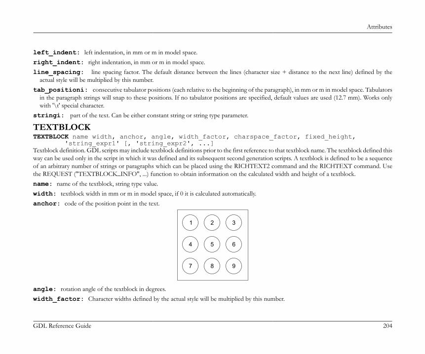
Attributes
GDL Reference Guide 204
left_indent: left indentation, in mm or m in model space.right_indent: right indentation, in mm or m in model space.line_spacing: line spacing factor. The default distance between the lines (character size + distance to the next line) defined by the
actual style will be multiplied by this number.tab_positioni: consecutive tabulator positions (each relative to the beginning of the paragraph), in mm or m in model space. Tabulators
in the paragraph strings will snap to these positions. If no tabulator positions are specified, default values are used (12.7 mm). Works onlywith '\t' special character.
stringi: part of the text. Can be either constant string or string type parameter.
TEXTBLOCKTEXTBLOCK name width, anchor, angle, width_factor, charspace_factor, fixed_height, 'string_expr1' [, 'string_expr2', ...]Textblock definition. GDL scripts may include textblock definitions prior to the first reference to that textblock name. The textblock defined thisway can be used only in the script in which it was defined and its subsequent second generation scripts. A textblock is defined to be a sequenceof an arbitrary number of strings or paragraphs which can be placed using the RICHTEXT2 command and the RICHTEXT command. Usethe REQUEST ("TEXTBLOCK_INFO", ...) function to obtain information on the calculated width and height of a textblock.name: name of the textblock, string type value.width: textblock width in mm or m in model space, if 0 it is calculated automatically.anchor: code of the position point in the text.
1 2 3
4 5 6
7 8 9
angle: rotation angle of the textblock in degrees.width_factor: Character widths defined by the actual style will be multiplied by this number.
Attributes
GDL Reference Guide 205
charspace_factor: The horizontal distance between two characters will be multiplied by this number.fixed_height: Possible values:1: the placed TEXTBLOCK will be scale-independent and all specified length type parameters will mean millimeters,0: the placed TEXTBLOCK will be scale-dependent and all specified length type parameters will mean meters in model space.
string_expri: means paragraph name if it was previously defined, simple string otherwise (with default paragraph parameters).
TEXTBLOCK_TEXTBLOCK_ name width, anchor, angle, width_factor, charspace_factor, fixed_height, 'string_expr1' [, 'string_expr2', ...]Similar to the TEXTBLOCK command. The meaning of all the parameters are the same, but the name of the textblock can be either stringor integer. And it can handle integer type named paragraphs as well.
Additional DataAttribute definitions can contain optional additional data definitions after the ADDITIONAL_DATA keyword. The additional data must beentered after the previously defined parameters of the attribute command. An additional data has a name (namei) and a value (valuei), which canbe an expression of any type, even an array. If a string parameter name ends with the substring "_file", its value is considered to be a file name andwill be included in the archive project. Different meanings of additional data can be defined and used by ArchiCAD or Add-Ons to ArchiCAD.See meanings of LightWorks Add-On parameters at http://www.graphisoft.com/support/developer/documentation/LibraryDevDoc/16/.Additional data definition is available in the following commands:DEFINE MATERIAL parameters [[,] ADDITIONAL_DATA name1 = value1, name2 = value2, ...]DEFINE MATERIAL name [,] BASED_ON orig_name [,] PARAMETERS name1 = expr1 [, ...] [[,] ADDITIONAL_DATA name1 = expr1 [, ...]]DEFINE FILL parameters [[,] ADDITIONAL_DATA name1 = value1, name2 = value2, ...]DEFINE FILLA parameters [[,] ADDITIONAL_DATA name1 = value1, name2 = value2, ...]DEFINE SYMBOL_FILL parameters [[,] ADDITIONAL_DATA name1 = value1, name2 = value2, ...]DEFINE SOLID_FILL name [[,] FILLTYPES_MASK fill_types] [[,] ADDITIONAL_DATA name1 = value1, name2 = value2, ...]DEFINE EMPTY_FILL name [[,] FILLTYPES_MASK fill_types] [[,] ADDITIONAL_DATA name1 = value1, name2 = value2, ...]DEFINE LINEAR_GRADIENT_FILL name [[,] FILLTYPES_MASK fill_types] [[,] ADDITIONAL_DATA name1 = value1, name2 = value2, ...]DEFINE RADIAL_GRADIENT_FILL name [[,] FILLTYPES_MASK fill_types] [[,] ADDITIONAL_DATA name1 = value1, name2 = value2, ...]
Attributes
GDL Reference Guide 206
DEFINE TRANSLUCENT_FILL name [[,] FILLTYPES_MASK fill_types] pat1, pat2, pat3, pat4, pat5, pat6, pat7, pat8, percentage [[,] ADDITIONAL_DATA name1 = value1, name2 = value2, ...]DEFINE IMAGE_FILL name image_name [[,] FILLTYPES_MASK fill_types] part1, part2, part3, part4, part5, part6, part7, part8, image_vert_size, image_hor_size, image_mask, image_rotangle [[,] ADDITIONAL_DATA name1 = value1, name2 = value2, ...]DEFINE LINE_TYPE parameters [[,] ADDITIONAL_DATA name1 = value1, name2 = value2, ...]DEFINE SYMBOL_LINE parameters [[,] ADDITIONAL_DATA name1 = value1, name2 = value2, ...]
EXTERNAL FILE DEPENDENCE
FILE_DEPENDENCEFILE_DEPENDENCE "name1" [, "name2", ...]You can give a list of external files on which your GDL script depends on. File names should be constant strings.All files specified here will be included in the archive project (like constant macro names used in CALL statements and constant picture namesused in various GDL commands). The command works on this level only: if the specified files are library parts, their called macro files willnot be included.The command can be useful in cases when external files are referenced at custom places in the GDL script, for example: ADDITIONAL_DATAfile parameters, data files in file operations.
Non-Geometric Scripts
GDL Reference Guide 207
NON-GEOMETRIC SCRIPTSIn addition to the 3D and 2D script windows that define the appearance of the GDL Object, further scripts are available for addingcomplementary information to it. These are the Properties Script used for quantity calculations, the Parameter Script that includes the list ofpossible values for different parameters, and the User Interface Script for creating a custom interface for parameter entry, Forward MigrationScript and Backward Migration Scripts to define how to migrate an old instance forward to the actual element or how to migrate the elementbackward to an older one. The commands available for all these script types are detailed on the following pages.
THE PROPERTIES SCRIPTLibrary parts have a GDL window reserved for the Properties script. This script allows you to make library part properties dependent onparameters, and, through a directive, define their place in the final component list. By using a few commands, it is possible to define in thescript local descriptors and components (created in the Properties windows of earlier ArchiCAD versions). Descriptors and components fromexternal databases can also be referenced. Code lengths cannot exceed 32 characters.In the Properties script, you can use any GDL command that does not generate a shape.
DATABASE_SETDATABASE_SET set_name [, descriptor_name, component_name, unit_name, key_name, criteria_name, list_set_name]Database set definition or Database set selection. If this command is placed in a MASTER_GDL script, it will define a Database set containingDescriptor, Component, Unit, Key, Criteria and List Scheme files.This Database set name can then be referenced from Properties Scripts using the same command with only the set_name parameter as adirective, by selecting the actual Database set that REF COMPONENTs and REF DESCRIPTORs refer to. The default Database set nameis "Default Set", and will be used if no other set has been selected. The default Database set file names are: DESCDATA, COMPDATA,COMPUNIT, LISTKEY, LISTCRIT, LISTSET. All these names get translated in localized ArchiCAD versions.Scripts can include any number of DATABASE_SET selections.set_name: database set name.descriptor_name: descriptor data file name.component_name: component data file name.unit_name: unit data file name.key_name: key data file name.criteria_name: criteria file name.
Non-Geometric Scripts
GDL Reference Guide 208
list_set_name: list Scheme file name.
DESCRIPTORDESCRIPTOR name [, code, keycode]Local descriptor definition. Scripts can include any number of DESCRIPTORs.name: can extend to more than one line. New lines can be defined by the character '\n' and tabulators by '\t'. Adding '\' to the end of a line
allows you to continue the string in the next line without adding a new line. Inside the string, if the '\' character is doubled (\\), it will loseits control function and simply mean '\'. The length of the string (including the new line characters) cannot exceed 255 characters: additionalcharacters will be simply cut by the compiler. If you need a longer text, use several DESCRIPTORs.
code: string, defines a code for the descriptor.keycode: string, reference to a key in an external database.The key will be assigned to the descriptor.
REF DESCRIPTORREF DESCRIPTOR code [, keycode]Reference by code and keycode string to a descriptor in an external database.
COMPONENTCOMPONENT name, quantity, unit [, proportional_with, code, keycode, unitcode]Local component definition. Scripts can include any number of COMPONENTs.name: the name of the component (max. 128 characters).quantity: a numeric expression.unit: the string used for unit description.proportional_with: a code between 1 and 6. When listing, the component quantity defined above will be automatically multiplied
by a value calculated for the current listed element:1: item,2: length,3: surface A,4: surface B,5: surface,6: volume.
Non-Geometric Scripts
GDL Reference Guide 209
code: string, defines a code for the component.keycode: string, reference to a key in an external database. The key will be assigned to the component.unitcode: string, reference to a unit in an external database that controls the output format of the component quantity. This will replace
the locally defined unit string.
REF COMPONENTREF COMPONENT code [, keycode [, numeric_expression]]Reference by code and keycode string to a component in an external database. The value to multiply by in the component database can beoverwritten by the optional numeric expression specified here.
BINARYPROPBINARYPROPBinaryprop is a reference to the binary properties data (components and descriptors) defined in the library part in the Components andDescriptors sections.DATABASE_SET directives have no effect on the binary data.
SURFACE3DSURFACE3D ()The Surface 3D () function gives you the surface of the 3D shape of the library part.Warning: If you place two or more shapes in the same location with the same parameters, this function will give you the total sum of all shapes’surfaces.
VOLUME3DVOLUME3D ()The Volume 3D () function gives you the volume of the 3D shape of the library part.Warning: If you place two or more shapes in the same location with the same parameters, this function will give you the total sum of all shapes’volumes.
POSITIONPOSITION position_keywordEffective only in the Component List.Changes only the type of the element the following descriptors and components are associated to. If there are no such directives in the Propertiesscript, descriptors and components will be listed with their default element types.
Non-Geometric Scripts
GDL Reference Guide 210
position_keyword: keywords are the following:WALLSCOLUMNSBEAMSDOORSWINDOWSOBJECTSCEILSPITCHED_ROOFSLIGHTSHATCHESROOMSMESHES
A directive remains valid for all succeeding DESCRIPTORs and COMPONENTs until the next directive is ascribed. A script can include anynumber of directives.
Example:DESCRIPTOR "\tPainted box.\n\t Properties:\n\\t\t - swinging doors\n\\t\t - adjustable height\n\\t\t - scratchproof"REF DESCRIPTOR "0001"s = SURFACE3D () !wardrobe surfaceCOMPONENT "glue", 1.5, "kg"COMPONENT "handle", 2*c, "nb" !c number of doorsCOMPONENT "paint", 0.5*s, "kg"POSITION WALLSREF COMPONENT "0002"
DRAWINGDRAWINGDRAWING: Refers to the drawing described in the 2D script of the same library part. Use it to place drawings in your bill of materials.
Non-Geometric Scripts
GDL Reference Guide 211
THE PARAMETER SCRIPTParameter lists are sets of possible numerical or string values. They can be applied to the parameters as defined in the Parameter Script of theLibrary Part or in the MASTER_GDL script. The parameter has to be of simple type. Type compatibility is verified by the GDL compiler.The Parameter Script will be interpreted each time a value list type parameter value is to be changed, and the possible values defined in thescript will appear in a pop-up menu.
VALUESVALUES "parameter_name" [,]value_definition1 [, value_definition2, ...]VALUES "fill_parameter_name" [[,] FILLTYPES_MASK fill_types,] value_definition1 [, value_definition2, ...]parameter_name: name of an existing parameterfill_parameter_name: name of an existing fillpattern type parameterfill_types:fill_types = j1 + 2*j2 + 4*j3, where each j can be 0 or 1.j1: cut fills,j2: cover fills,j3: drafting fills.
Can be used for fill-pattern type parameters only. The fill popup for this parameter will contain only those types of fills which are specifiedby the bits set to 1. Default is all fills (0).value_definitioni: value definition, can be:expression: numerical or string expression, orCUSTOM: keyword, meaning that any custom value can be entered, orRANGE: range definition, with optional stepRANGE left_delimiter[lower_limit], [upper_limit]right_delimiter [STEP step_start_value,step_value]left_delimiter: [, meaning >=, or (, meaning >; lower_limit: lower limit expression; upper_limit: upper limit expression; right_delimiter: ],meaning <=, or ), meaning <; step_start_value: starting value; step_value: step value.
Example 1: Simple value listsVALUES "par1" 1, 2, 3VALUES "par2" "a", "b"VALUES "par3" 1, CUSTOM, SIN (30)VALUES "par4" 4, RANGE(5, 10], 12, RANGE(,20] STEP 14.5, 0.5, CUSTOM
Non-Geometric Scripts
GDL Reference Guide 212
Example 2: Read all string values from a file for use in a value listDIM sarray[]! file in the library, containing parameter datafilename = "ProjectNotes.txt"ch1 = OPEN ("text", filename, "MODE=RO, LIBRARY")i = 1j = 1sarray[1] = ""! collect all stringsDO n = INPUT (ch1, i, 1, var) IF n > 0 AND VARTYPE (var) = 2 THEN sarray[j] = var j = j + 1 ENDIF i = i + 1WHILE n > 0CLOSE ch1! parameter popup with strings read from the fileVALUES "RefNote" sarray
PARAMETERSPARAMETERS name1 = expression1 [, name2 = expression2, ..., namen = expressionn]namei: the name of the parameter.expressioni: the new value of the parameter.Using this command, the parameter values of a Library Part can be modified by the Parameter Script.The modification will only be effective for the next interpretation. Commands in macros refer to the caller’s parameters. If the parameter is avalue list, the value chosen will be either an existing value, the custom value, or the first value from the value list.In addition, the global string variable GLOB_MODPAR_NAME contains the name of the last user-modified parameter.
LOCKLOCK name1 [, name2, ..., namen]Locks the named parameter(s) in the settings dialog box. A locked parameter will appear grayed in the dialog box and its value cannot bemodified by the user.
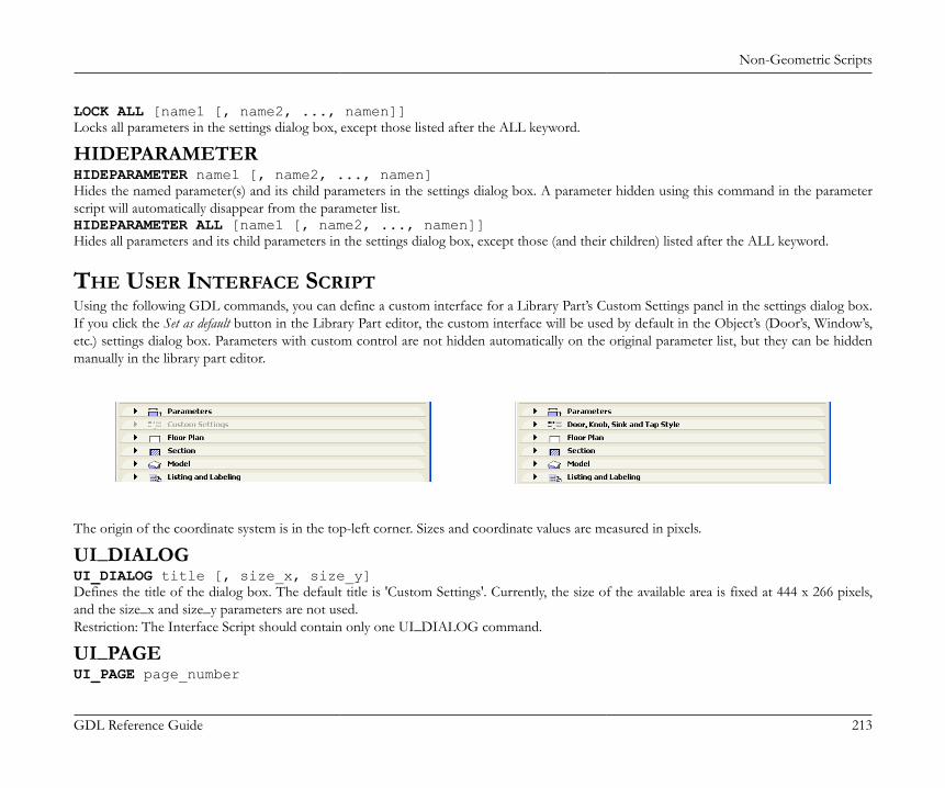
Non-Geometric Scripts
GDL Reference Guide 213
LOCK ALL [name1 [, name2, ..., namen]]Locks all parameters in the settings dialog box, except those listed after the ALL keyword.
HIDEPARAMETERHIDEPARAMETER name1 [, name2, ..., namen]Hides the named parameter(s) and its child parameters in the settings dialog box. A parameter hidden using this command in the parameterscript will automatically disappear from the parameter list.HIDEPARAMETER ALL [name1 [, name2, ..., namen]]Hides all parameters and its child parameters in the settings dialog box, except those (and their children) listed after the ALL keyword.
THE USER INTERFACE SCRIPTUsing the following GDL commands, you can define a custom interface for a Library Part’s Custom Settings panel in the settings dialog box.If you click the Set as default button in the Library Part editor, the custom interface will be used by default in the Object’s (Door’s, Window’s,etc.) settings dialog box. Parameters with custom control are not hidden automatically on the original parameter list, but they can be hiddenmanually in the library part editor.
The origin of the coordinate system is in the top-left corner. Sizes and coordinate values are measured in pixels.
UI_DIALOGUI_DIALOG title [, size_x, size_y]Defines the title of the dialog box. The default title is 'Custom Settings'. Currently, the size of the available area is fixed at 444 x 266 pixels,and the size_x and size_y parameters are not used.Restriction: The Interface Script should contain only one UI_DIALOG command.
UI_PAGEUI_PAGE page_number
Non-Geometric Scripts
GDL Reference Guide 214
Page directive, defines the page that the interface elements are placed on. Page numbering starts at 1. Moving between pages can be defined intwo different ways. The first method is to use two buttons created with the UI_NEXT and UI_PREV commands. The second way is to createdynamic page handling using the UI_CURRENT_PAGE command.If there is no UI_PAGE command in the Interface Script, each element will be placed on the first page by default.Warning: In the simple way of paging, any break of continuity in the page numbering forces the insertion of a new page without buttons, andtherefore there will be no possibility to go to any other page from there. This restriction can be circumvented using the UI_CURRENT_PAGEcommand.
UI_CURRENT_PAGEUI_CURRENT_PAGE indexDefinition of the current tabpage to display.Warning: Jumping to a non-existent page forces the insertion of a new page without buttons and controls, and therefore there is no possibilityto go to any other page from there.index: valid index of the UI_PAGE to display.
UI_BUTTONUI_BUTTON type, text, x, y [, width, height, id [, url]]Button definition on current page. Buttons can be used for various purposes: moving from page to page, opening a web page or performingsome parameter-script defined action. Buttons can contain text.type: type of the button as follows:UI_PREV: if pressed, the previous page is displayed,UI_NEXT: if pressed, the next page is displayed,UI_FUNCTION: if pressed, the GLOB_UI_BUTTON_ID global variable is set to the button id specified in expression,UI_LINK: if pressed, the URL in expression is opened in the default web browser,
text: the text that should appear on the text type button; picture buttons omit this parameter.x, y: the position of the button.width, height: width and height of the button in pixels. If not specified (for compatibility reasons) the default values are 60 pixels
for width and 20 pixels for height.id: an integer unique identifier.url: a string containing a URL.UI_PREV and UI_NEXT buttons are disabled if the previous/next page is not present. If these buttons are pushed, the gs_ui_current_pageparameter of the library part is set to the index of the page to show - if there’s a parameter with this name.
Non-Geometric Scripts
GDL Reference Guide 215
Example:! UI scriptUI_CURRENT_PAGE gs_ui_current_pageUI_BUTTON UI_FUNCTION, "Go to page 9", 200,150, 70,20, 3UI_BUTTON UI_LINK, "Visit Website", 200,180, 100,20, 0, "http://www.graphisoft.com"! parameter scriptif GLOB_UI_BUTTON_ID = 3 then parameters gs_ui_current_page = 9, ...endif
UI_PICT_BUTTONUI_PICT_BUTTON type, text, picture_reference, x, y, width, height [, id [, url]]Similar to the UI_BUTTON command. But this type of buttons can contain pictures.picture_reference: file name or index number of the picture stored in the library part. The index 0 refers to the preview picture of
the library part. Pixel transparency is allowed in the picture.text: has no effect for picture buttons.
UI_SEPARATORUI_SEPARATOR x1, y1, x2, y2Generates a separator rectangle. The rectangle becomes a single (vertical or horizontal) separator line if x1 = x2 or y1 = y2x1, y1: upper left node coordinates (starting point coordinates of the line).x2, y2: lower right node coordinates (endpoint coordinates of the line).
UI_GROUPBOXUI_GROUPBOX text, x, y, width, heightA groupbox is a rectangular separator with caption text. It can be used to visually group logically related parameters.text: the title of the groupbox.x, y: the position of upper left corner.width, height: width and height in pixels.
UI_PICTUI_PICT picture_reference, x, y [, width, height [, mask]]
Non-Geometric Scripts
GDL Reference Guide 216
Picture element in the dialog box. The picture file must be located in one of the loaded libraries.picture_reference: file name or index number of the picture stored in the library part. The index 0 refers to the preview picture
of the library part.x, y: position of the top left corner of the picture.width, height: optional width and height in pixels; by default, the picture’s original width and height values will be used.mask: alpha + distortion.See the PICTURE command for full explanation.
UI_STYLEUI_STYLE fontsize, face_codeAll the UI_OUTFIELDs and UI_INFIELDs generated after this keyword will represent this style until the next UI_STYLE statement.fontsize: one of the following font size values:0: small,1: extra small,2: large.
face_code: similar to the STYLE definition, but the values cannot be used in combination.0: normal,1: bold,2: italic,4: underline,8: outline,16: shadow.
Note: The outline and shadow values are effective only on Macintosh platform and up to the 8.1 version of ArchiCAD.
UI_OUTFIELDUI_OUTFIELD expression, x, y [, width, height [, flags]]Generates a static text.expression: numerical or string expression.x, y: position of the text block’s top left corner.width, height: width and height of the text box. If omitted, the text box will wrap around the text as tight as possible for the given font.
Non-Geometric Scripts
GDL Reference Guide 217
flags:flags = j1 + 2*j2 + 4*j3, where each j can be 0 or 1.j1: horizontal alignment (with j2),j2: horizontal alignment (with j1):j1 = 0, j2 = 0: Aligns to the left edge (default),j1 = 1, j2 = 0: Aligns to the right edge,j1 = 0, j2 = 1: Aligns to the center,j1 = 1, j2 = 1: Not used,j3: grayed text.
UI_INFIELDUI_INFIELD "name", x, y, width, height [, method, picture_name, images_number, rows_number, cell_x, cell_y, image_x, image_y, expression_image1, text1, ..., expression_imagen, textn]
UI_INFIELD{2}UI_INFIELD{2} name, x, y, width, height [, method, picture_name, images_number, rows_number, cell_x, cell_y, image_x, image_y, expression_image1, text1, ..., expression_imagen, textn]
Non-Geometric Scripts
GDL Reference Guide 218
UI_INFIELD{3}UI_INFIELD{3} name, x, y, width, height [, method, picture_name, images_number, rows_number, cell_x, cell_y, image_x, image_y, expression_image1, text1, value_definition1, ..., expression_imagen, textn, value_definitionn]Generates an edit text or a pop-up menu for the parameter input. A pop-up is generated if the parameter type is value list, material, fill, linetype or pencolor.If the optional parameters of the command are present, value lists can be alternatively displayed as thumbnail view fields. Different thumbnailcontrol types are available. They display the specified images and associated texts and allow the selection of one single item at a time, just likein a pop-up menu.In the version 1 and 2 infield, the thumbnail items and the value list items are associated by indices.The version 3 infield defines value association which binds the thumbnail items to value list items of the associated parameter. If a value definedin a thumbnail item isn’t present in the parameter’s value list, it won’t be displayed in the control.The Interface Script is rebuilt with the new value after any parameter is modified.name: parameter name as string expression for UI_INFIELD or parameter name with optional actual index values if array for
UI_INFIELD{2} and UI_INFIELD{3}.x, y: the position of the edit text, pop-up or control.width, height: width and height in pixels.method: the type of the control.1: List view control.
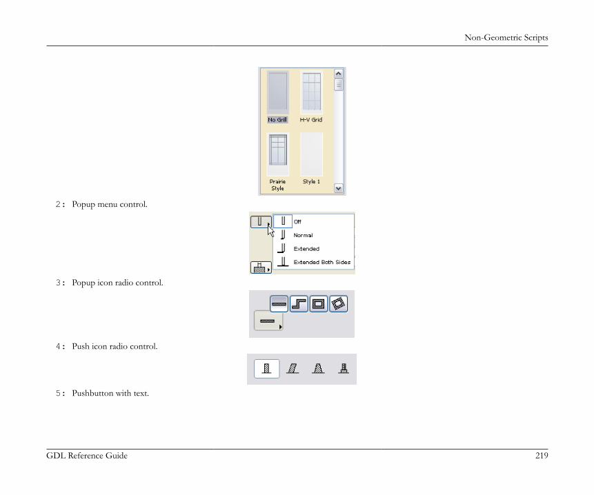
Non-Geometric Scripts
GDL Reference Guide 219
2: Popup menu control.
3: Popup icon radio control.
4: Push icon radio control.
5: Pushbutton with text.
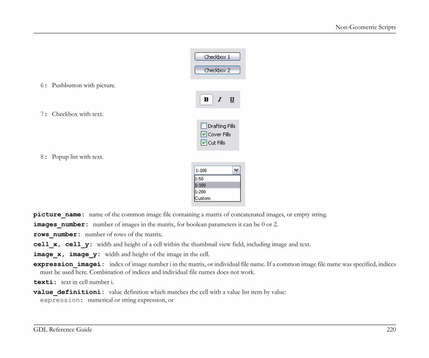
Non-Geometric Scripts
GDL Reference Guide 220
6: Pushbutton with picture.
7: Checkbox with text.
8: Popup list with text.
picture_name: name of the common image file containing a matrix of concatenated images, or empty string.images_number: number of images in the matrix, for boolean parameters it can be 0 or 2.rows_number: number of rows of the matrix.cell_x, cell_y: width and height of a cell within the thumbnail view field, including image and text.image_x, image_y: width and height of the image in the cell.expression_imagei: index of image number i in the matrix, or individual file name. If a common image file name was specified, indices
must be used here. Combination of indices and individual file names does not work.texti: text in cell number i.value_definitioni: value definition which matches the cell with a value list item by value:expression: numerical or string expression, or
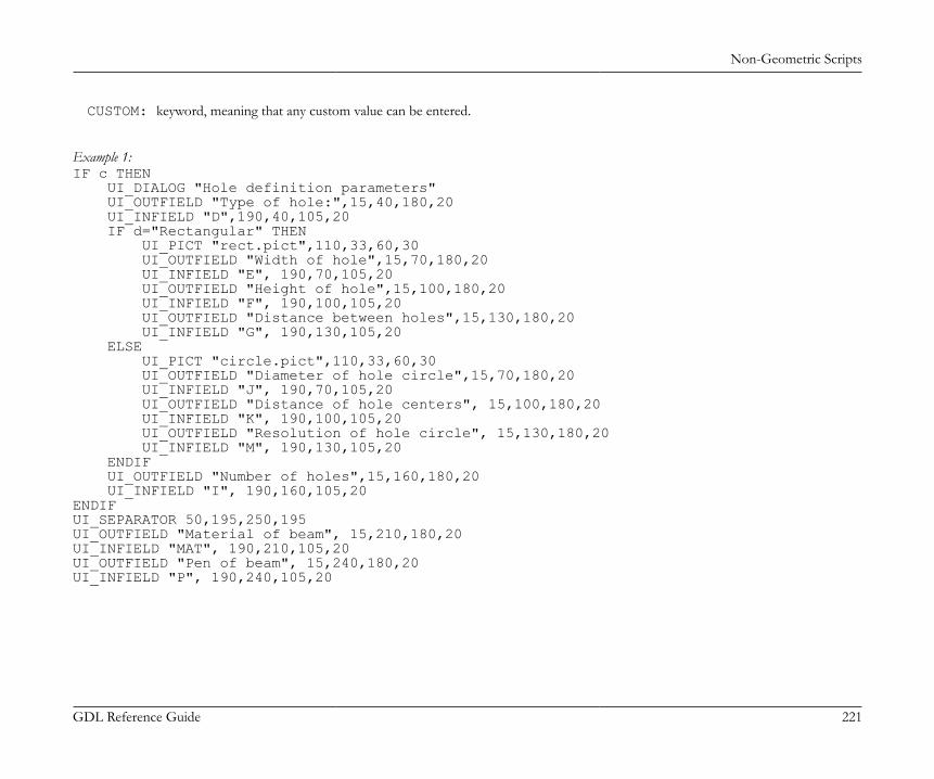
Non-Geometric Scripts
GDL Reference Guide 221
CUSTOM: keyword, meaning that any custom value can be entered.
Example 1:IF c THEN UI_DIALOG "Hole definition parameters" UI_OUTFIELD "Type of hole:",15,40,180,20 UI_INFIELD "D",190,40,105,20 IF d="Rectangular" THEN UI_PICT "rect.pict",110,33,60,30 UI_OUTFIELD "Width of hole",15,70,180,20 UI_INFIELD "E", 190,70,105,20 UI_OUTFIELD "Height of hole",15,100,180,20 UI_INFIELD "F", 190,100,105,20 UI_OUTFIELD "Distance between holes",15,130,180,20 UI_INFIELD "G", 190,130,105,20 ELSE UI_PICT "circle.pict",110,33,60,30 UI_OUTFIELD "Diameter of hole circle",15,70,180,20 UI_INFIELD "J", 190,70,105,20 UI_OUTFIELD "Distance of hole centers", 15,100,180,20 UI_INFIELD "K", 190,100,105,20 UI_OUTFIELD "Resolution of hole circle", 15,130,180,20 UI_INFIELD "M", 190,130,105,20 ENDIF UI_OUTFIELD "Number of holes",15,160,180,20 UI_INFIELD "I", 190,160,105,20ENDIFUI_SEPARATOR 50,195,250,195UI_OUTFIELD "Material of beam", 15,210,180,20UI_INFIELD "MAT", 190,210,105,20UI_OUTFIELD "Pen of beam", 15,240,180,20UI_INFIELD "P", 190,240,105,20
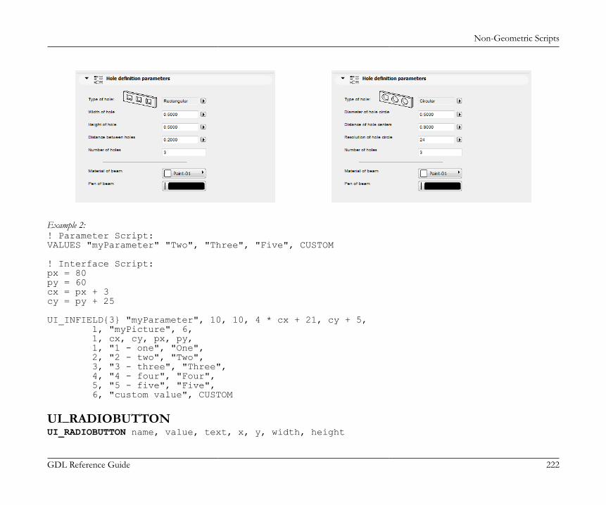
Non-Geometric Scripts
GDL Reference Guide 222
Example 2:! Parameter Script:VALUES "myParameter" "Two", "Three", "Five", CUSTOM
! Interface Script:px = 80py = 60cx = px + 3cy = py + 25
UI_INFIELD{3} "myParameter", 10, 10, 4 * cx + 21, cy + 5, 1, "myPicture", 6, 1, cx, cy, px, py, 1, "1 - one", "One", 2, "2 - two", "Two", 3, "3 - three", "Three", 4, "4 - four", "Four", 5, "5 - five", "Five", 6, "custom value", CUSTOM
UI_RADIOBUTTONUI_RADIOBUTTON name, value, text, x, y, width, height

Non-Geometric Scripts
GDL Reference Guide 223
Generates a radio button of a radio button group. Radio button groups are defined by the parameter name. Items in the same group aremutually exclusive.name: parameter name with optional actual index values if array.value: parameter is set to this value if this radio button is set.text: this text is displayed beside the radio button.x, y: the position of the radio control.width, height: width and height in pixels.
Example:UI_RADIOBUTTON "ceilingPlan", 0, `Floor Plan`, 10, 140, 100, 20UI_RADIOBUTTON "ceilingPlan", 1, `Ceiling Plan`, 10, 160, 100, 20
UI_TOOLTIPUI_BUTTON type, text, x, y, width, height [, id [, url]] [ UI_TOOLTIP tooltiptext ]UI_PICT_BUTTON type, text, picture_reference, x, y, width, height [, id [, url]] [ UI_TOOLTIP tooltiptext ]UI_INFIELD "name", x, y, width, height [, extra parameters ... ] [ UI_TOOLTIP tooltiptext ]UI_INFIELD{2} name, x, y, width, height [, extra parameters ... ] [ UI_TOOLTIP tooltiptext ]UI_INFIELD{3} name, x, y, width, height [, extra parameters ... ] [ UI_TOOLTIP tooltiptext ]UI_RADIOBUTTON name, value, text, x, y, width, height [ UI_TOOLTIP tooltiptext ]UI_OUTFIELD expression, x, y, width, height [, flags] [ UI_TOOLTIP tooltiptext ]UI_PICT expression, x, y [, width, height [, mask]] [ UI_TOOLTIP tooltiptext ]Defines the tooltip for the control on the user interface page. Tooltips are available for buttons, infields, outfields and pictures if they are notdisabled by the user in the running context (f. ex. in the Help menu of ArchiCAD).tooltiptext: the text to display as tooltip for the control.
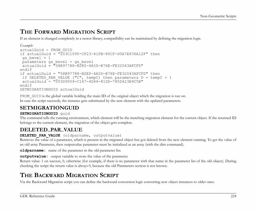
Non-Geometric Scripts
GDL Reference Guide 224
THE FORWARD MIGRATION SCRIPTIf an element is changed completely in a newer library, compatibility can be maintained by defining the migration logic.
Example:actualGuid = FROM_GUIDif actualGuid = "203C1090-CF23-41FB-80CF-D0A7E836A12F" then gs_bevel = 1 parameters gs_bevel = gs_bevel actualGuid = "58B97788-B2E0-4A5D-B76E-FE32043AFCFD"endifif actualGuid = "58B97788-B2E0-4A5D-B76E-FE32043AFCFD" then if DELETED_PAR_VALUE ("C", tempC) then parameters D = tempC + 1 actualGuid = "053D9059-C147-4D44-81DD-785D423B9C5B"endifSETMIGRATIONGUID actualGuid
FROM_GUID is the global variable holding the main ID of the original object which the migration is run on.In case the script succeeds, the instance gets substituted by the new element with the updated parameters.
SETMIGRATIONGUIDSETMIGRATIONGUID guidThe command tells the running environment, which element will be the matching migration element for the current object. If the returned IDbelongs to the current element, the migration of the object gets complete.
DELETED_PAR_VALUEDELETED_PAR_VALUE (oldparname, outputvalue)Retrieves the value of a parameter, which is present in the migrated object but got deleted from the new element running. To get the value ofan old array Parameter, then outputvalue parameter must be initialized as an array (with the dim command).oldparname: name of the parameter in the old parameter list.outputvalue: output variable to store the value of the parameter.Return value: 1 on success, 0, otherwise (for example, if there is no parameter with that name in the parameter list of the old object). Duringchecking the script the return value is always 0, because the old Parameters section is not known.
THE BACKWARD MIGRATION SCRIPTVia the Backward Migration script you can define the backward conversion logic converting new object instances to older ones.
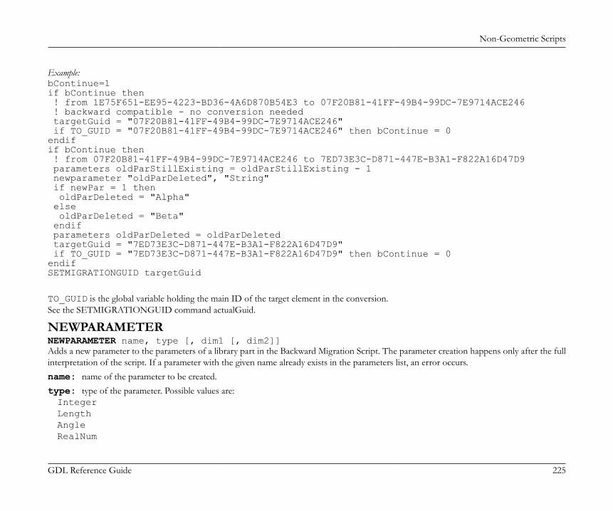
Non-Geometric Scripts
GDL Reference Guide 225
Example:bContinue=1if bContinue then ! from 1E75F651-EE95-4223-BD36-4A6D870B54E3 to 07F20B81-41FF-49B4-99DC-7E9714ACE246 ! backward compatible - no conversion needed targetGuid = "07F20B81-41FF-49B4-99DC-7E9714ACE246" if TO_GUID = "07F20B81-41FF-49B4-99DC-7E9714ACE246" then bContinue = 0endifif bContinue then ! from 07F20B81-41FF-49B4-99DC-7E9714ACE246 to 7ED73E3C-D871-447E-B3A1-F822A16D47D9 parameters oldParStillExisting = oldParStillExisting - 1 newparameter "oldParDeleted", "String" if newPar = 1 then oldParDeleted = "Alpha" else oldParDeleted = "Beta" endif parameters oldParDeleted = oldParDeleted targetGuid = "7ED73E3C-D871-447E-B3A1-F822A16D47D9" if TO_GUID = "7ED73E3C-D871-447E-B3A1-F822A16D47D9" then bContinue = 0endifSETMIGRATIONGUID targetGuid
TO_GUID is the global variable holding the main ID of the target element in the conversion.See the SETMIGRATIONGUID command actualGuid.
NEWPARAMETERNEWPARAMETER name, type [, dim1 [, dim2]]Adds a new parameter to the parameters of a library part in the Backward Migration Script. The parameter creation happens only after the fullinterpretation of the script. If a parameter with the given name already exists in the parameters list, an error occurs.name: name of the parameter to be created.type: type of the parameter. Possible values are:IntegerLengthAngleRealNum
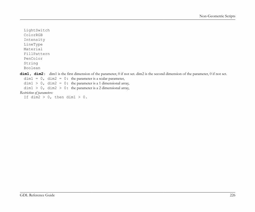
Non-Geometric Scripts
GDL Reference Guide 226
LightSwitchColorRGBIntensityLineTypeMaterialFillPatternPenColorStringBoolean
dim1, dim2: dim1 is the first dimension of the parameter, 0 if not set. dim2 is the second dimension of the parameter, 0 if not set.dim1 = 0, dim2 = 0: the parameter is a scalar parameter,dim1 > 0, dim2 = 0: the parameter is a 1 dimensional array,dim1 > 0, dim2 > 0: the parameter is a 2 dimensional array,
Restriction of parameters:If dim2 > 0, then dim1 > 0.
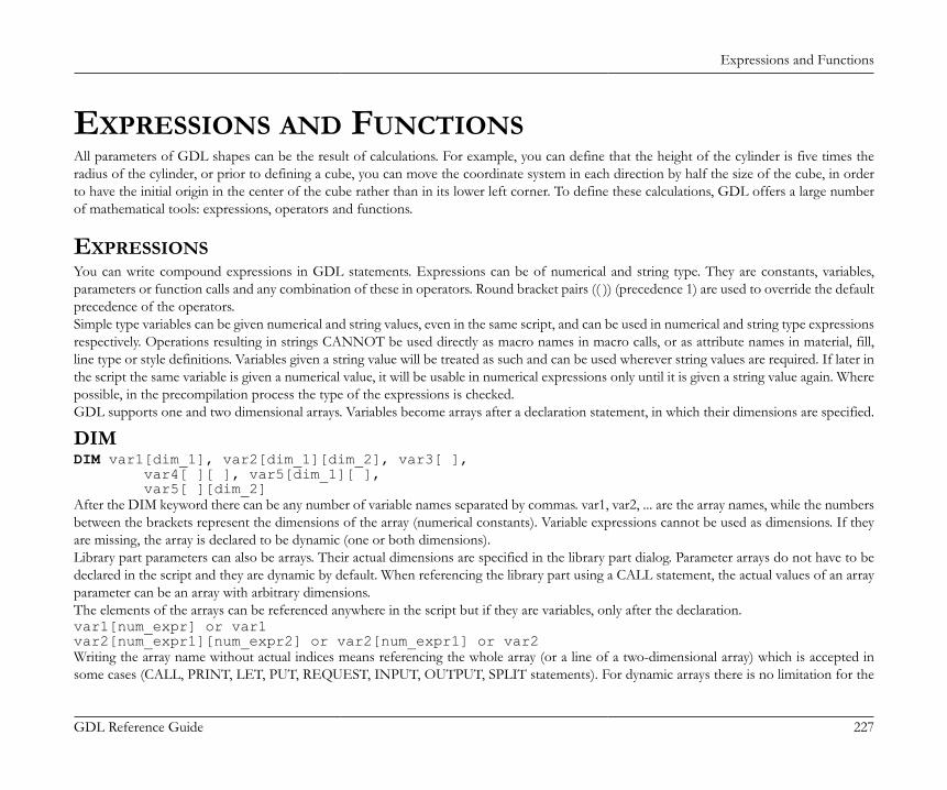
Expressions and Functions
GDL Reference Guide 227
EXPRESSIONS AND FUNCTIONSAll parameters of GDL shapes can be the result of calculations. For example, you can define that the height of the cylinder is five times theradius of the cylinder, or prior to defining a cube, you can move the coordinate system in each direction by half the size of the cube, in orderto have the initial origin in the center of the cube rather than in its lower left corner. To define these calculations, GDL offers a large numberof mathematical tools: expressions, operators and functions.
EXPRESSIONSYou can write compound expressions in GDL statements. Expressions can be of numerical and string type. They are constants, variables,parameters or function calls and any combination of these in operators. Round bracket pairs (( )) (precedence 1) are used to override the defaultprecedence of the operators.Simple type variables can be given numerical and string values, even in the same script, and can be used in numerical and string type expressionsrespectively. Operations resulting in strings CANNOT be used directly as macro names in macro calls, or as attribute names in material, fill,line type or style definitions. Variables given a string value will be treated as such and can be used wherever string values are required. If later inthe script the same variable is given a numerical value, it will be usable in numerical expressions only until it is given a string value again. Wherepossible, in the precompilation process the type of the expressions is checked.GDL supports one and two dimensional arrays. Variables become arrays after a declaration statement, in which their dimensions are specified.
DIMDIM var1[dim_1], var2[dim_1][dim_2], var3[ ], var4[ ][ ], var5[dim_1][ ], var5[ ][dim_2]After the DIM keyword there can be any number of variable names separated by commas. var1, var2, ... are the array names, while the numbersbetween the brackets represent the dimensions of the array (numerical constants). Variable expressions cannot be used as dimensions. If theyare missing, the array is declared to be dynamic (one or both dimensions).Library part parameters can also be arrays. Their actual dimensions are specified in the library part dialog. Parameter arrays do not have to bedeclared in the script and they are dynamic by default. When referencing the library part using a CALL statement, the actual values of an arrayparameter can be an array with arbitrary dimensions.The elements of the arrays can be referenced anywhere in the script but if they are variables, only after the declaration.var1[num_expr] or var1var2[num_expr1][num_expr2] or var2[num_expr1] or var2Writing the array name without actual indices means referencing the whole array (or a line of a two-dimensional array) which is accepted insome cases (CALL, PRINT, LET, PUT, REQUEST, INPUT, OUTPUT, SPLIT statements). For dynamic arrays there is no limitation for the
Expressions and Functions
GDL Reference Guide 228
actual index value. During the interpretation, when a non-existing dynamic array element is given a value, the necessary quantity of memoryis allocated and the missing elements are all set to 0 (numerical).Warning! This may cause an unexpected out of memory error in some cases. Each index - even of a possibly wrong, huge value - is consideredvalid, since the interpreter is unable to detect the error condition. A non-existing dynamic array element is 0 (numerical).Arrays having a fixed dimension are checked for the validity of the actual index on the fixed dimension. Array variables with fixed length cannotaccept dynamic array values in assignments. However, dynamic arrays that are given whole array values will take on those values. This alsoapplies to some statements where whole array references can be used as return parameters. (REQUEST, INPUT, SPLIT).Array elements can be used in any numerical or string expression. They can be given string or numerical values.Indices start with 1, and any numerical expression can be used as an index.Array elements can be of different simple types (numerical, string, group). The type of the whole array (main type) is the type of its first element([1] or [1][1]). Parameter and global variable arrays cannot be of mixed type.
VARDIM1VARDIM1 (expr)
VARDIM2VARDIM2 (expr)These functions return as integers the actual dimension values for the (array) expression specified as a parameter. They must be used if youwant to handle correctly all actual elements of a dynamic array or an array parameter. If no element of a dynamic array was previously set, thereturn value is 0. For one-dimensional arrays VARDIM2 returns 0.
Example 1: Examples for numeric expressions:Z5.5(+15)-xa*(b+c)SIN(x+y)*za+r*COS(i*d)5' 4"SQR (x^2 + y^2) / (1 - d)a + b * sin (alpha)height * width
Expressions and Functions
GDL Reference Guide 229
Example 2: Examples for string expressions:"Constant string"name + STR ("%m", i) + "." + extstring_param <> "Mode 1"
Example 3: Examples for expressions using array values:DIM tab[5], tab2[3][4] ! declarationtab[1] + tab[2]tab2[2][3] + APRINT tabDIM f1 [5], v1[], v2[][]v1[3] = 3 ! v1[1] = 0, v1[2] = 0, array of 3 elementsv2[2][3] = 23 ! all other elements(2 X 3) = 0PRINT v1, v2DIM f1 [5], v1[], v2[][]FOR i = 1 TO VARDIM1(f1) f1[i] = iNEXT iv1 = f1v2 [1] = f1PRINT v1, v2
OPERATORSThe operators below are listed in order of decreasing precedence. The evaluation of an expression begins with the highest precedence operatorand from left to right.
Arithmetical Operators
^ (or **) Power of precedence 2
* Multiplication precedence 3
/ Division precedence 3MOD (or %) Modulo (remainder of division) x MOD y = x - y * INT (x/y) precedence 3
+ Addition precedence 4
- Subtraction precedence 4
Expressions and Functions
GDL Reference Guide 230
Note+ (addition) can also be applied to string expressions: the result is the concatenation of the strings. The result of the '/' (Division)is always a real number, while the result of the other operations depends on the type of the operands: if all operands are integer, theresult will be integer, otherwise real.
Relational Operators
= Equal precedence 5
< Less than precedence 5
> Greater than precedence 5
<= Less than or equal precedence 5
>= Greater than or equal precedence 5
<> (or #) Not equal precedence 5
NoteThese operators can be used between any two string expressions also (string comparison is case sensitive). The result is an integer, 1or 0. There is not recommended to use the '=' (Equal), '<=' (Less than or equal), '>=' (Greater than or equal), '<>' (or #) (Not equal)operators with real operands, as these operations can result in precision problems.
Boolean Operators
AND (or &) Logical and precedence 6OR (or |) Logical inclusive or precedence 7EXOR (or @) Logical exclusive or precedence 8
NoteBoolean operators work with integer numbers. In consequence, 0 means false, while any other number means true. The value of alogical expression is also integer, i.e., 1 for true and 0 for false. It is not recommended to use boolean operators with real operands,as these operations can result in precision problems.
Expressions and Functions
GDL Reference Guide 231
FUNCTIONS
Arithmetical FunctionsABSABS (x)Returns the absolute value of x (integer if x integer, real otherwise).
CEILCEIL (x)Returns the smallest integral value that is not smaller than x (always integer). (e.g., CEIL(1.23) = 2; CEIL (-1.9) = -1).
INTINT (x)Returns the integral part of x (always integer). (e.g., INT(1.23) = 1, INT(-1.23) = -2).
FRAFRA (x)Returns the fractional part of x (integer 0 if x integer, real otherwise). (e.g., FRA(1.23) = 0.23, FRA(-1.23) = 0.77).
ROUND_INTROUND_INT (x)Returns the rounded integer part of x. The 'i = ROUND_INT (x)' expression is equivalent with the following script:IF x < 0.0 THEN i = INT (x - 0.5) ELSE i = INT (x + 0.5)
SGNSGN (x)Returns +1 integer if x positive, -1 integer if x negative, otherwise 0 integer.
SQRSQR (x)Returns the square root of x (always real).
Expressions and Functions
GDL Reference Guide 232
Circular FunctionsThese functions use degrees for arguments (COS, SIN, TAN) and for return values (ACS, ASN, ATN).
ACSACS (x)Returns the arc cosine of x. (-1.0 <= x <= 1.0; 0° <= ACS(x) <= 180°).
ASNASN (x)Returns the arc sine of x. (-1.0 <= x <= 1.0; -90° <= ASN(x) <= 90°).
ATNATN (x)Returns the arc tangent of x. (-90° <= ATN(x) <= 90°).
COSCOS (x)Returns the cosine of x.
SINSIN (x)Returns the sine of x.
TANTAN (x)Returns the tangent of x.
PIPIReturns Ludolph’s constant. (p = 3.1415926...).
Note: All return values are real.
Expressions and Functions
GDL Reference Guide 233
Transcendental FunctionsEXPEXP (x)Returns the x th power of e (e = 2.7182818).
LGTLGT (x)Returns the base 10 logarithm of x.
LOGLOG (x)Returns the natural logarithm of x.
Note: All returned values are real.
Boolean FunctionsNOTNOT (x)Returns false (=0 integer) if x is true (<>0), and true (=1 integer) if x is false (=0)(logical negation).
Note: Parameter value should be integer.
Statistical FunctionsMINMIN (x1, x2, ... xn)Returns the smallest of an unlimited number of arguments.
MAXMAX (x1, x2, ... xn)Returns the largest of an unlimited number of arguments.
RNDRND (x)
Expressions and Functions
GDL Reference Guide 234
Returns a random value between 0.0 and x (x > 0.0) always real.
Bit FunctionsBITTESTBITTEST (x, b)Returns 1 if the b bit of x is set, 0 otherwise.
BITSETBITSET (x, b [, expr])expr can be 0 or different, the default value is 1. Sets the b bit of x to 1 or 0 depending on the value of the specified expression, and returnsthe result. Parameter value should be integer, returned value is integer.
Special FunctionsSpecial functions (besides global variables) can be used in the script to communicate with the executing program. They either ask the currentstate and different preferences settings of the program, or refer to the current environment of the library part. Request calls can also be usedto communicate with GDL extensions.
REQREQ (parameter_string)Asks the current state of the program. Its parameter - the question - is a string. The GDL interpreter answers with a numeric value. If it doesnot understand the question, the answer is negative.parameter_string: question string, one of the following:"GDL_version": version number of the GDL compiler/interpreter. Warning: it is not the same as the ArchiCAD version."Program": code of the program (e.g., 1: ArchiCAD),"Serial_number": the serial number of the keyplug,"Model_size": size of the current 3D data structure in bytes,"Red_of_material name""Green_of_material name""Blue_of_material name": Defines the given material’s color components in RGB values between 0 and 1,"Red_of_pen index""Green_of_pen index""Blue_of_pen index": Defines the given pen’s color components in RGB values between 0 and 1,
Expressions and Functions
GDL Reference Guide 235
"Pen_of_RGB r g b": Defines the index of the pen closest to the given color. The r, g and b constants’ values are between 0 and 1.
REQUESTREQUEST (question_name, name | index, variable1 [, variable2, ...])The first parameter represents the question string while the second represents the object of the question (if it exists) and can be of either stringor numeric type (for example, the question can be "Rgb_of_material" and its object the material’s name, or "Rgb_of_pen" and its object theindex of the pen). The other parameters are variable names in which the return values (the answers) are stored.The return value of the requests is always the number of successfully retrieved values (integer), while the type of the retrieved values is definedby each request in part. In the case of a badly formulated question or a nonexistent name, the return value will be 0.For the list of available options see the section called “REQUEST Options”.
INDIND (MATERIAL, name_stringIND (FILL, name_string)IND (LINE_TYPE, name_string)IND (STYLE, name_string)IND (TEXTURE, name_string)This function returns the current index of the material, fill, line type or style and texture attribute. The main use of the resulting number is totransfer it to a macro that requires the same attribute as the calling macro.The functions return an attribute index (integer) value. The result is negative for temporary definitions (inside the script or from Master_GDLfile) and positive for global definitions (from the project attributes).See also the section called “Inline Attribute Definition”.
APPLICATION_QUERYAPPLICATION_QUERY (extension_name, parameter_string, variable1, variable2, ...)GDL allows a way for the individual applications to provide specific request functions in their context. These query options aren’t definedin the GDL syntax; consult the GDL developer documentation of the given application for specific options. Basic Library Documentationapplies for ArchiCAD.
LIBRARYGLOBALLIBRARYGLOBAL (object_name, parameter, value)Fills value with the current model view option parameter value of the library global object defined by object_name if available. A library globalsetting is available if the global object is currently loaded in the library, or was loaded earlier and its setting was saved in the current modelview option combination.Returns 1 if successful, 0 otherwise.
Expressions and Functions
GDL Reference Guide 236
object_name: name of library global object. Must be a string constant. Warning: If string variables or parameters are used as object names,then the 2d and 3d view of objects querying this library global object will not refresh automatically.
parameter: name of requested parameter.value: filled with the requested parameter value.
Example:success = LIBRARYGLOBAL ("MyGlobalOptions", "detLevel2D", det)if success > 0 then text2 0, 0, detelse text2 0, 0, "Not available"endif
String FunctionsSTRSTR (numeric_expression, length, fractions)STR (format_string, numeric_expression)The first form of the function creates a string from the current value of the numeric expression. The minimum number for numerical charactersin the string is length, while fractions represents the numbers following the floating point. If the converted value has more than length characters,it is expanded as required. If it has fewer characters, it is padded on the left (length > 0) or on the right (length < 0).In the second form, the format_string can either be a variable or a constant. If the format is empty, it is interpreted as meters, with an accuracyof three decimals (displaying 0s).
Example:a=4.5b=2.345TEXT2 0, 2, STR(a, 8, 2) ! 4.50TEXT2 0, 1, STR(b, 8, 2) ! 2.34TEXT2 0, 0, STR(a*b, 8, 2) ! 10.55
STR{2}STR{2} (format_string, numeric_expression [, extra_accuracy_string])Extension of the second form of STR. If the extra accuracy flags are set in the format_string, then the STR{2} function will return thecorresponding extra accuracy string in the 3rd parameter.
Expressions and Functions
GDL Reference Guide 237
format_string: "%[0 or more flags][field_width][.precision] conv_spec"flags: (for m, mm, cm, e, df, di, sqm, sqcm, sqf, sqi, dd, gr, rad, cum, l, cucm, cumm, cuf, cui, cuy, gal):(none): right justify (default),-: left justify,+: explicit plus sign,(space): in place of a + sign,'*' 0: extra accuracy Off (default),'*' 1: extra accuracy .5,'*' 2: extra accuracy .25,'*' 3: extra accuracy .1,'*' 4: extra accuracy .01,'*' 5: extra accuracy .5,'*' 6: extra accuracy .25,'#': don’t display 0s (for m, mm, cm, df, di, sqm, sqcm, sqf, sqi, dd, fr, rad, cum, l, cucm, cumm, cuf, cui, cuy, gal),'0': display 0 inches (for ffi, fdi, fi),'~': hide 0 decimals (effective only if the '#' flag is not specified) (for m, mm, cm, fdi, df, di, sqm, sqcm, sqf, sqi, dd, fr, rad, cum, l,cucm, cumm, cuf, cui, cuy, gal),'^': do not change decimal separator and digit grouping characters (if not specified, these characters will be replaced as set in the currentsystem).
field_width: unsigned decimal integer, the minimum number of characters to generate.precision: unsigned decimal integer, the number of fraction digits to generate.conv_spec: (conversion specifier):e: exponential format (meter),m: meters,mm: millimeters,cm: centimeters,ffi: feet & fractional inches,fdi: feet & decimal inches,df: decimal feet,fi: fractional inches,di: decimal inches,
Expressions and Functions
GDL Reference Guide 238
pt: points,for areas:sqm: square meters,sqcm: square centimeters,sqmm: square millimeters,sqf: square feet,sqi: square inches,for angles:dd: decimal degrees,dms: degrees, minutes, seconds,gr: grads,rad: radians,surv: surveyors unit,for volumes:cum: cubic meters,l: liters,cucm: cubic centimeters,cumm: cubic millimeters,cuf: cubic feet,cui: cubic inches,cuy: cubic yards,gal: gallons.
Expressions and Functions
GDL Reference Guide 239
Example:nr = 0.345678TEXT2 0, 23, STR ("%m", nr) !0.346TEXT2 0, 22, STR ("%#10.2m", nr) !35TEXT2 0, 21, STR ("%.4cm", nr) !34.5678TEXT2 0, 20, STR ("%12.4cm", nr) ! 34.5678TEXT2 0, 19, STR ("%.6mm", nr) !345.678000TEXT2 0, 18, STR ("%+15e", nr) !+3.456780e-01TEXT2 0, 17, STR ("%ffi", nr) !1'-2"TEXT2 0, 16, STR ("%0.16ffi", nr) !1'-1 5/8"TEXT2 0, 15, STR ("% .3fdi", nr) ! 1'-1.609"TEXT2 0, 14, STR ("% -10.4df", nr) ! 1.1341'TEXT2 0, 13, STR ("%0.64fi", nr) !13 39/64"TEXT2 0, 12, STR ("%+12.4di", nr)!+13.6094"TEXT2 0, 11, STR ("%#.3sqm", nr) !346TEXT2 0, 10, STR ("%+sqcm", nr) !+3,456.78TEXT2 0, 9, STR ("% .2sqmm", nr)! 345,678.00TEXT2 0, 8, STR ("%-12sqf", nr) !3.72TEXT2 0, 7, STR ("%10sqi", nr) ! 535.80TEXT2 0, 6, STR ("%.2pt", nr) !0.35alpha = 88.657TEXT2 0, 5, STR ("%+10.3dd", alpha) !+88.657°TEXT2 0, 4, STR ("%.1dms", alpha) !88°39'TEXT2 0, 3, STR ("%.2dms", alpha) !88°39'25"TEXT2 0, 2, STR ("%10.4gr", alpha) ! 98.5078GTEXT2 0, 1, STR ("%rad", alpha) !1.55RTEXT2 0, 0, STR ("%.2surv", alpha) !N 1°20'35" E
SPLITSPLIT (string, format, variable1 [, variable2, ..., variablen])Splits the string parameter according to the format in one or more numeric or string parts. The split process stops when the first non-matchingpart is encountered. Returns the number of successfully read values (integer).string: the string to be split.format: any combination of constant strings, %s, %n and %^n -s. Parts in the string must fit the constant strings, %s denotes any string
value delimited by spaces or tabs, while %n or %^n denotes any numeric value. If the '^' flag is present, current system settings for decimalseparator and digit grouping characters are taken into consideration when matching the actual numerical value.
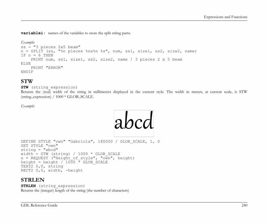
Expressions and Functions
GDL Reference Guide 240
variablei: names of the variables to store the split string parts.
Example:ss = "3 pieces 2x5 beam"n = SPLIT (ss, "%n pieces %nx%n %s", num, ss1, size1, ss2, size2, name)IF n = 6 THEN PRINT num, ss1, size1, ss2, size2, name ! 3 pieces 2 x 5 beamELSE PRINT "ERROR"ENDIF
STWSTW (string_expression)Returns the (real) width of the string in millimeters displayed in the current style. The width in meters, at current scale, is STW(string_expression) / 1000 * GLOB_SCALE.
Example:
DEFINE STYLE "own" "Gabriola", 180000 / GLOB_SCALE, 1, 0SET STYLE "own"string = "abcd"width = STW (string) / 1000 * GLOB_SCALEn = REQUEST ("Height_of_style", "own", height)height = height / 1000 * GLOB_SCALETEXT2 0,0, stringRECT2 0,0, width, -height
STRLENSTRLEN (string_expression)Returns the (integer) length of the string (the number of characters)
Expressions and Functions
GDL Reference Guide 241
STRSTRSTRSTR (string_expression1, string_expression2)Returns the (integer) position of the first appearance of the second string in the first string. If the first string doesn’t contain the second one,the function returns 0.
Example:szFormat = ""n = REQUEST ("Linear_dimension", "", szFormat)unit = ""IF STRSTR (szFormat, "m") > 0 THEN unit = "m"IF STRSTR (szFormat, "mm") > 0 THEN unit = "mm"IF STRSTR (szFormat, "cm") > 0 THEN unit = "cm"TEXT2 0, 0, STR (szFormat, a) + " " + unit !1.00 m
STRSUBSTRSUB (string_expression, start_position, characters_number)Returns a substring of the string parameter that begins at the position given by the start_position parameter and its length is characters_numbercharacters.
Example:string = "Flowers.jpeg"len = STRLEN (string)iDotPos = STRSTR (string, ".")TEXT2 0, -1, STRSUB (string, 1, iDotPos - 1) !FlowersTEXT2 0, -2, STRSUB (string, len - 4, 5) !.jpeg
Control Statements
GDL Reference Guide 242
CONTROL STATEMENTSThis chapter reviews the GDL commands available for controlling loops and subroutines in scripts and introduces the concept of buffer manipulation designed to storeparameter values for further use. It also explains how to use objects as macro calls and how to display calculated expressions on screen.
FLOW CONTROL STATEMENTS
FOR - TO - NEXTFOR variable_name = initial_value TO end_value [ STEP step_value ] NEXT variable_nameFOR is the first statement of a FOR loop.NEXT is the last statement of a FOR loop.The loop variable varies from the initial_value to the end_value by the step_value increment (or decrement) in each execution of the body ofthe loop (statements between the FOR and NEXT statements). If the loop variable exceeds the value of the end_value, the program executesthe statement following the NEXT statement.If the STEP keyword and the step_value are missing, the step is assumed to be 1.
Note: Changing the step_value during the execution of the loop has no effect.A global variable is not allowed as a loop control variable.
Example 1:FOR i=1 TO 10 STEP 2 PRINT iNEXT i
Control Statements
GDL Reference Guide 243
Example 2:! The two program fragments below are equivalent:
! 1sta = b1:IF c > 0 AND a > d OR c < 0 AND a < d THEN 2PRINT aa = a + cGOTO 1
! 2nd2:FOR a = b TO d STEP c PRINT aNEXT aThe above example shows that step_value = 0 causes an infinite loop.Only one NEXT statement is allowed after a FOR statement. You can exit the loop with the GOTO command and to return after leaving,but you cannot enter a loop skipping the FOR statement.
DO - WHILEDO [statment1 statement2 ... statementn]WHILE conditionThe statements between the keywords are executed as long as the condition is true.The condition is checked after each execution of the statements.
WHILE - ENDWHILEWHILE condition DO [statement1 statement2 ... statementn]ENDWHILEThe statements between the keywords are executed as long as the condition is true.
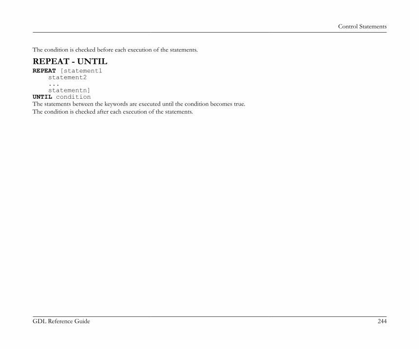
Control Statements
GDL Reference Guide 244
The condition is checked before each execution of the statements.
REPEAT - UNTILREPEAT [statement1 statement2 ... statementn]UNTIL conditionThe statements between the keywords are executed until the condition becomes true.The condition is checked after each execution of the statements.
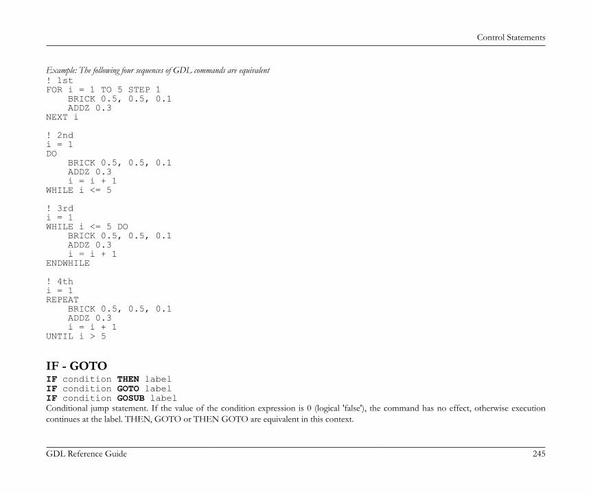
Control Statements
GDL Reference Guide 245
Example: The following four sequences of GDL commands are equivalent! 1stFOR i = 1 TO 5 STEP 1 BRICK 0.5, 0.5, 0.1 ADDZ 0.3NEXT i
! 2ndi = 1DO BRICK 0.5, 0.5, 0.1 ADDZ 0.3 i = i + 1WHILE i <= 5
! 3rdi = 1WHILE i <= 5 DO BRICK 0.5, 0.5, 0.1 ADDZ 0.3 i = i + 1ENDWHILE
! 4thi = 1REPEAT BRICK 0.5, 0.5, 0.1 ADDZ 0.3 i = i + 1UNTIL i > 5
IF - GOTOIF condition THEN labelIF condition GOTO labelIF condition GOSUB labelConditional jump statement. If the value of the condition expression is 0 (logical 'false'), the command has no effect, otherwise executioncontinues at the label. THEN, GOTO or THEN GOTO are equivalent in this context.
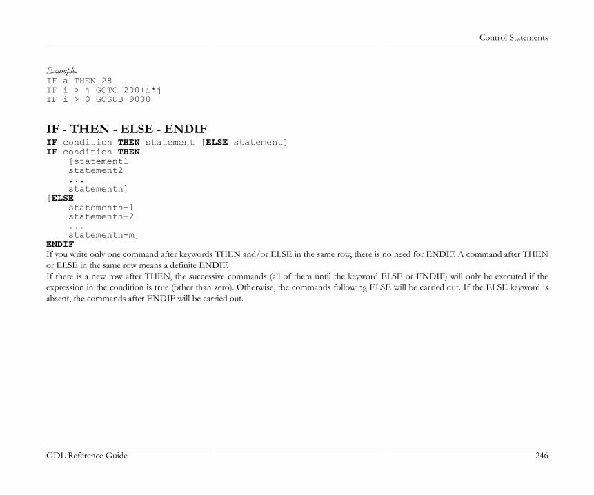
Control Statements
GDL Reference Guide 246
Example:IF a THEN 28IF i > j GOTO 200+i*jIF i > 0 GOSUB 9000
IF - THEN - ELSE - ENDIFIF condition THEN statement [ELSE statement]IF condition THEN [statement1 statement2 ... statementn][ELSE statementn+1 statementn+2 ... statementn+m]ENDIFIf you write only one command after keywords THEN and/or ELSE in the same row, there is no need for ENDIF. A command after THENor ELSE in the same row means a definite ENDIF.If there is a new row after THEN, the successive commands (all of them until the keyword ELSE or ENDIF) will only be executed if theexpression in the condition is true (other than zero). Otherwise, the commands following ELSE will be carried out. If the ELSE keyword isabsent, the commands after ENDIF will be carried out.
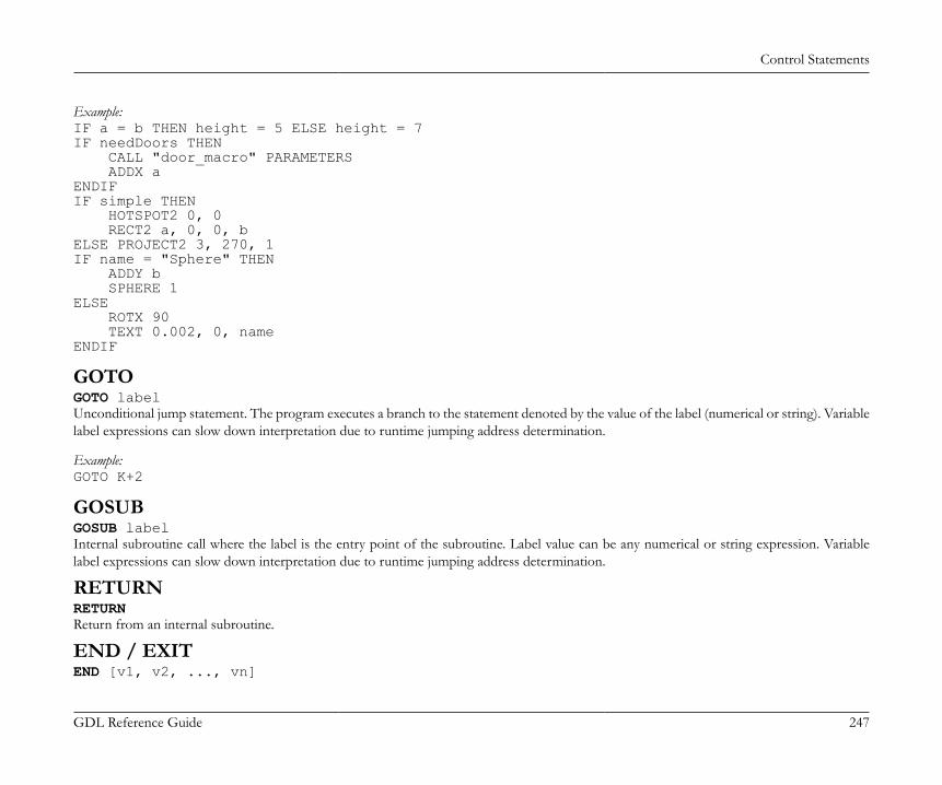
Control Statements
GDL Reference Guide 247
Example:IF a = b THEN height = 5 ELSE height = 7IF needDoors THEN CALL "door_macro" PARAMETERS ADDX aENDIFIF simple THEN HOTSPOT2 0, 0 RECT2 a, 0, 0, bELSE PROJECT2 3, 270, 1IF name = "Sphere" THEN ADDY b SPHERE 1ELSE ROTX 90 TEXT 0.002, 0, nameENDIF
GOTOGOTO labelUnconditional jump statement. The program executes a branch to the statement denoted by the value of the label (numerical or string). Variablelabel expressions can slow down interpretation due to runtime jumping address determination.
Example:GOTO K+2
GOSUBGOSUB labelInternal subroutine call where the label is the entry point of the subroutine. Label value can be any numerical or string expression. Variablelabel expressions can slow down interpretation due to runtime jumping address determination.
RETURNRETURNReturn from an internal subroutine.
END / EXITEND [v1, v2, ..., vn]
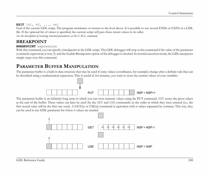
Control Statements
GDL Reference Guide 248
EXIT [v1, v2, ..., vn]End of the current GDL script. The program terminates or returns to the level above. It is possible to use several ENDs or EXITs in a GDLfile. If the optional list of values is specified, the current script will pass these return values to its caller.See the description of receiving returned parameters at the CALL command.
BREAKPOINTBREAKPOINT expressionWith this command, you can specify a breakpoint in the GDL script. The GDL debugger will stop at this command if the value of the parameter(a numeric expression) is true (1) and the Enable Breakpoints option of the debugger is checked. In normal execution mode, the GDL interpretersimply steps over this command.
PARAMETER BUFFER MANIPULATIONThe parameter buffer is a built-in data structure that may be used if some values (coordinates, for example) change after a definite rule that canbe described using a mathematical expression. This is useful if, for instance, you want to store the current values of your variables.
PUT NSP = NSP+1
The parameter buffer is an infinitely long array in which you can store numeric values using the PUT command. PUT stores the given valuesat the end of the buffer. These values can later be used (by the GET and USE commands) in the order in which they were entered (i.e., thefirst stored value will be the first one used). A GET(n) or USE(n) command is equivalent with n values separated by commas. This way, theycan be used in any GDL parameter list where n values are needed.
GET NSP = NSP-1
USE NSP = NSP
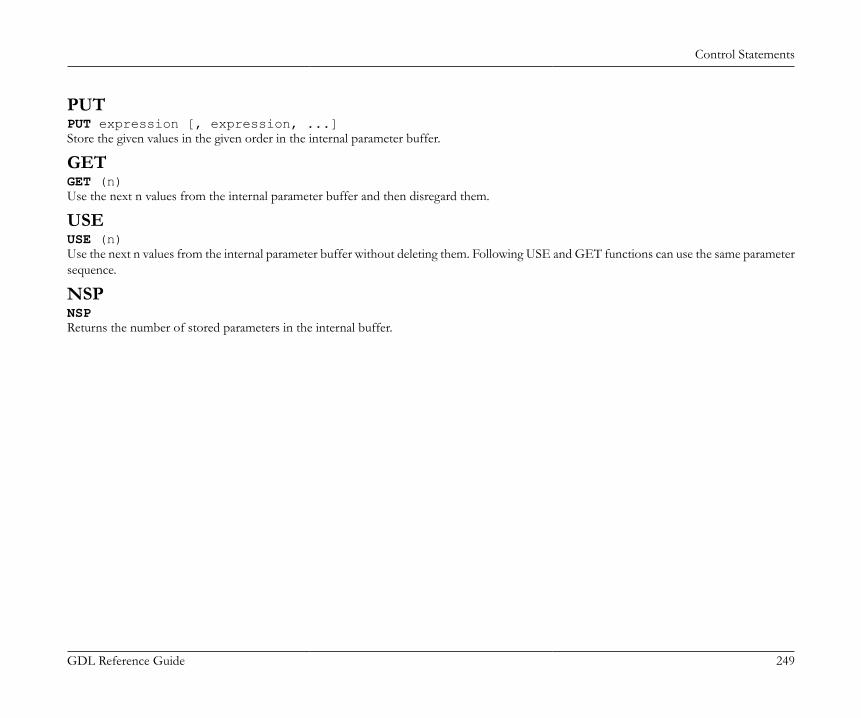
Control Statements
GDL Reference Guide 249
PUTPUT expression [, expression, ...]Store the given values in the given order in the internal parameter buffer.
GETGET (n)Use the next n values from the internal parameter buffer and then disregard them.
USEUSE (n)Use the next n values from the internal parameter buffer without deleting them. Following USE and GET functions can use the same parametersequence.
NSPNSPReturns the number of stored parameters in the internal buffer.
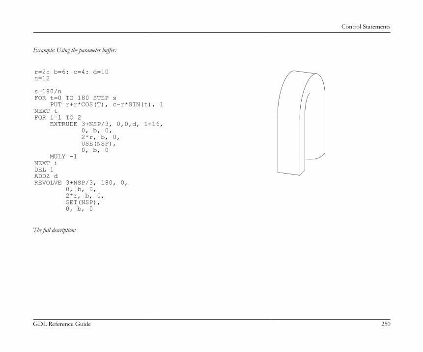
Control Statements
GDL Reference Guide 250
Example: Using the parameter buffer:
r=2: b=6: c=4: d=10n=12
s=180/nFOR t=0 TO 180 STEP s PUT r+r*COS(T), c-r*SIN(t), 1NEXT tFOR i=1 TO 2 EXTRUDE 3+NSP/3, 0,0,d, 1+16, 0, b, 0, 2*r, b, 0, USE(NSP), 0, b, 0 MULY -1NEXT iDEL 1ADDZ dREVOLVE 3+NSP/3, 180, 0, 0, b, 0, 2*r, b, 0, GET(NSP), 0, b, 0
The full description:
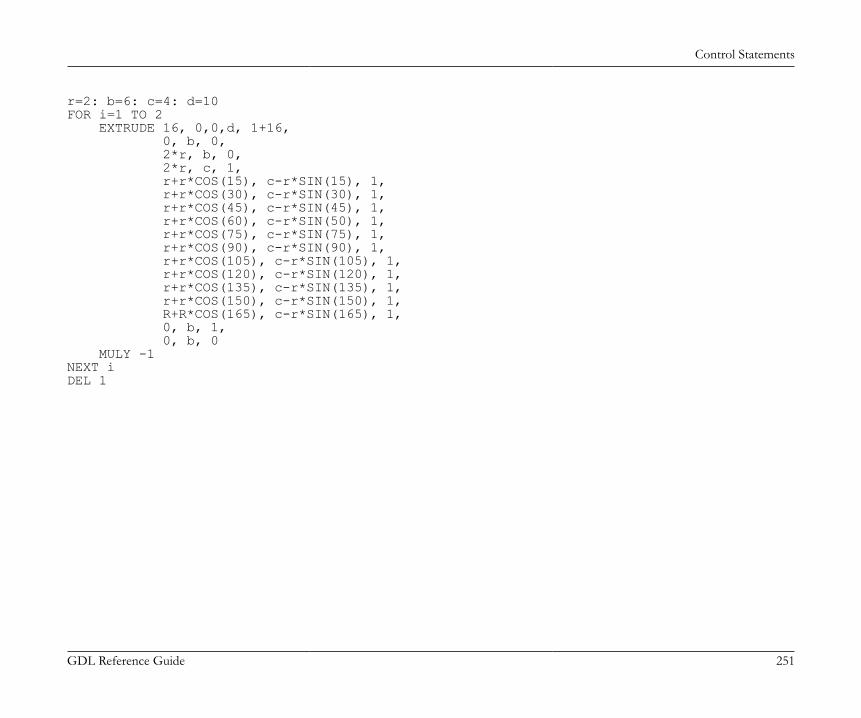
Control Statements
GDL Reference Guide 251
r=2: b=6: c=4: d=10FOR i=1 TO 2 EXTRUDE 16, 0,0,d, 1+16, 0, b, 0, 2*r, b, 0, 2*r, c, 1, r+r*COS(15), c-r*SIN(15), 1, r+r*COS(30), c-r*SIN(30), 1, r+r*COS(45), c-r*SIN(45), 1, r+r*COS(60), c-r*SIN(50), 1, r+r*COS(75), c-r*SIN(75), 1, r+r*COS(90), c-r*SIN(90), 1, r+r*COS(105), c-r*SIN(105), 1, r+r*COS(120), c-r*SIN(120), 1, r+r*COS(135), c-r*SIN(135), 1, r+r*COS(150), c-r*SIN(150), 1, R+R*COS(165), c-r*SIN(165), 1, 0, b, 1, 0, b, 0 MULY -1NEXT iDEL 1
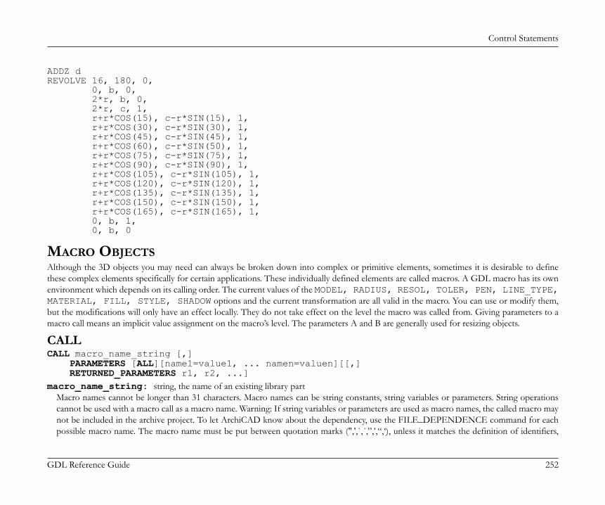
Control Statements
GDL Reference Guide 252
ADDZ dREVOLVE 16, 180, 0, 0, b, 0, 2*r, b, 0, 2*r, c, 1, r+r*COS(15), c-r*SIN(15), 1, r+r*COS(30), c-r*SIN(30), 1, r+r*COS(45), c-r*SIN(45), 1, r+r*COS(60), c-r*SIN(50), 1, r+r*COS(75), c-r*SIN(75), 1, r+r*COS(90), c-r*SIN(90), 1, r+r*COS(105), c-r*SIN(105), 1, r+r*COS(120), c-r*SIN(120), 1, r+r*COS(135), c-r*SIN(135), 1, r+r*COS(150), c-r*SIN(150), 1, r+r*COS(165), c-r*SIN(165), 1, 0, b, 1, 0, b, 0
MACRO OBJECTSAlthough the 3D objects you may need can always be broken down into complex or primitive elements, sometimes it is desirable to definethese complex elements specifically for certain applications. These individually defined elements are called macros. A GDL macro has its ownenvironment which depends on its calling order. The current values of the MODEL, RADIUS, RESOL, TOLER, PEN, LINE_TYPE,MATERIAL, FILL, STYLE, SHADOW options and the current transformation are all valid in the macro. You can use or modify them,but the modifications will only have an effect locally. They do not take effect on the level the macro was called from. Giving parameters to amacro call means an implicit value assignment on the macro’s level. The parameters A and B are generally used for resizing objects.
CALLCALL macro_name_string [,] PARAMETERS [ALL][name1=value1, ... namen=valuen][[,] RETURNED_PARAMETERS r1, r2, ...]macro_name_string: string, the name of an existing library part
Macro names cannot be longer than 31 characters. Macro names can be string constants, string variables or parameters. String operationscannot be used with a macro call as a macro name. Warning: If string variables or parameters are used as macro names, the called macro maynot be included in the archive project. To let ArchiCAD know about the dependency, use the FILE_DEPENDENCE command for eachpossible macro name. The macro name must be put between quotation marks (",',`,´,”,’,“,‘), unless it matches the definition of identifiers,
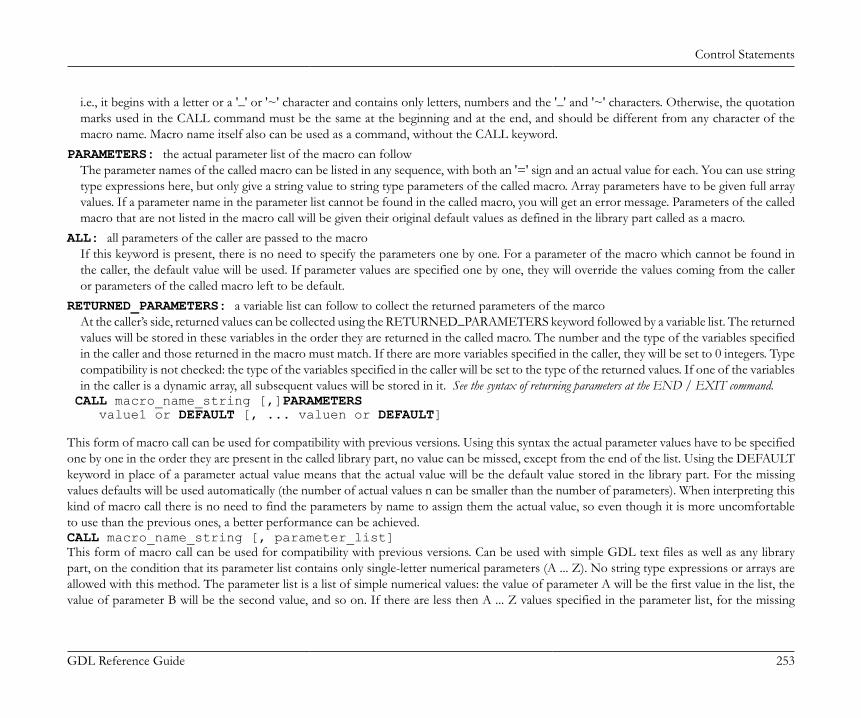
Control Statements
GDL Reference Guide 253
i.e., it begins with a letter or a '_' or '~' character and contains only letters, numbers and the '_' and '~' characters. Otherwise, the quotationmarks used in the CALL command must be the same at the beginning and at the end, and should be different from any character of themacro name. Macro name itself also can be used as a command, without the CALL keyword.
PARAMETERS: the actual parameter list of the macro can followThe parameter names of the called macro can be listed in any sequence, with both an '=' sign and an actual value for each. You can use stringtype expressions here, but only give a string value to string type parameters of the called macro. Array parameters have to be given full arrayvalues. If a parameter name in the parameter list cannot be found in the called macro, you will get an error message. Parameters of the calledmacro that are not listed in the macro call will be given their original default values as defined in the library part called as a macro.
ALL: all parameters of the caller are passed to the macroIf this keyword is present, there is no need to specify the parameters one by one. For a parameter of the macro which cannot be found inthe caller, the default value will be used. If parameter values are specified one by one, they will override the values coming from the calleror parameters of the called macro left to be default.
RETURNED_PARAMETERS: a variable list can follow to collect the returned parameters of the marcoAt the caller’s side, returned values can be collected using the RETURNED_PARAMETERS keyword followed by a variable list. The returnedvalues will be stored in these variables in the order they are returned in the called macro. The number and the type of the variables specifiedin the caller and those returned in the macro must match. If there are more variables specified in the caller, they will be set to 0 integers. Typecompatibility is not checked: the type of the variables specified in the caller will be set to the type of the returned values. If one of the variablesin the caller is a dynamic array, all subsequent values will be stored in it. See the syntax of returning parameters at the END / EXIT command.
CALL macro_name_string [,]PARAMETERS value1 or DEFAULT [, ... valuen or DEFAULT] This form of macro call can be used for compatibility with previous versions. Using this syntax the actual parameter values have to be specifiedone by one in the order they are present in the called library part, no value can be missed, except from the end of the list. Using the DEFAULTkeyword in place of a parameter actual value means that the actual value will be the default value stored in the library part. For the missingvalues defaults will be used automatically (the number of actual values n can be smaller than the number of parameters). When interpreting thiskind of macro call there is no need to find the parameters by name to assign them the actual value, so even though it is more uncomfortableto use than the previous ones, a better performance can be achieved.CALL macro_name_string [, parameter_list]This form of macro call can be used for compatibility with previous versions. Can be used with simple GDL text files as well as any librarypart, on the condition that its parameter list contains only single-letter numerical parameters (A ... Z). No string type expressions or arrays areallowed with this method. The parameter list is a list of simple numerical values: the value of parameter A will be the first value in the list, thevalue of parameter B will be the second value, and so on. If there are less then A ... Z values specified in the parameter list, for the missing
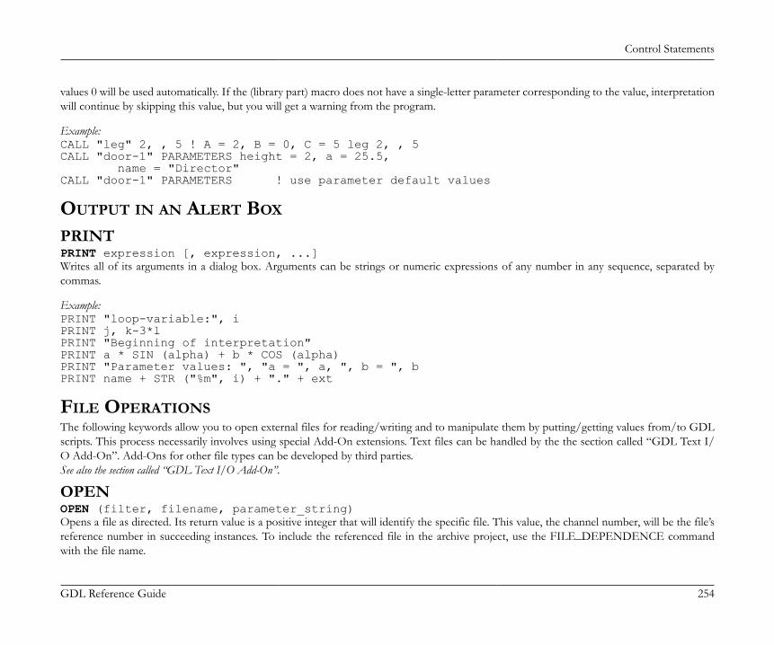
Control Statements
GDL Reference Guide 254
values 0 will be used automatically. If the (library part) macro does not have a single-letter parameter corresponding to the value, interpretationwill continue by skipping this value, but you will get a warning from the program.
Example:CALL "leg" 2, , 5 ! A = 2, B = 0, C = 5 leg 2, , 5CALL "door-1" PARAMETERS height = 2, a = 25.5, name = "Director"CALL "door-1" PARAMETERS ! use parameter default values
OUTPUT IN AN ALERT BOX
PRINTPRINT expression [, expression, ...]Writes all of its arguments in a dialog box. Arguments can be strings or numeric expressions of any number in any sequence, separated bycommas.
Example:PRINT "loop-variable:", iPRINT j, k-3*lPRINT "Beginning of interpretation"PRINT a * SIN (alpha) + b * COS (alpha)PRINT "Parameter values: ", "a = ", a, ", b = ", bPRINT name + STR ("%m", i) + "." + ext
FILE OPERATIONSThe following keywords allow you to open external files for reading/writing and to manipulate them by putting/getting values from/to GDLscripts. This process necessarily involves using special Add-On extensions. Text files can be handled by the the section called “GDL Text I/O Add-On”. Add-Ons for other file types can be developed by third parties.See also the section called “GDL Text I/O Add-On”.
OPENOPEN (filter, filename, parameter_string)Opens a file as directed. Its return value is a positive integer that will identify the specific file. This value, the channel number, will be the file’sreference number in succeeding instances. To include the referenced file in the archive project, use the FILE_DEPENDENCE commandwith the file name.
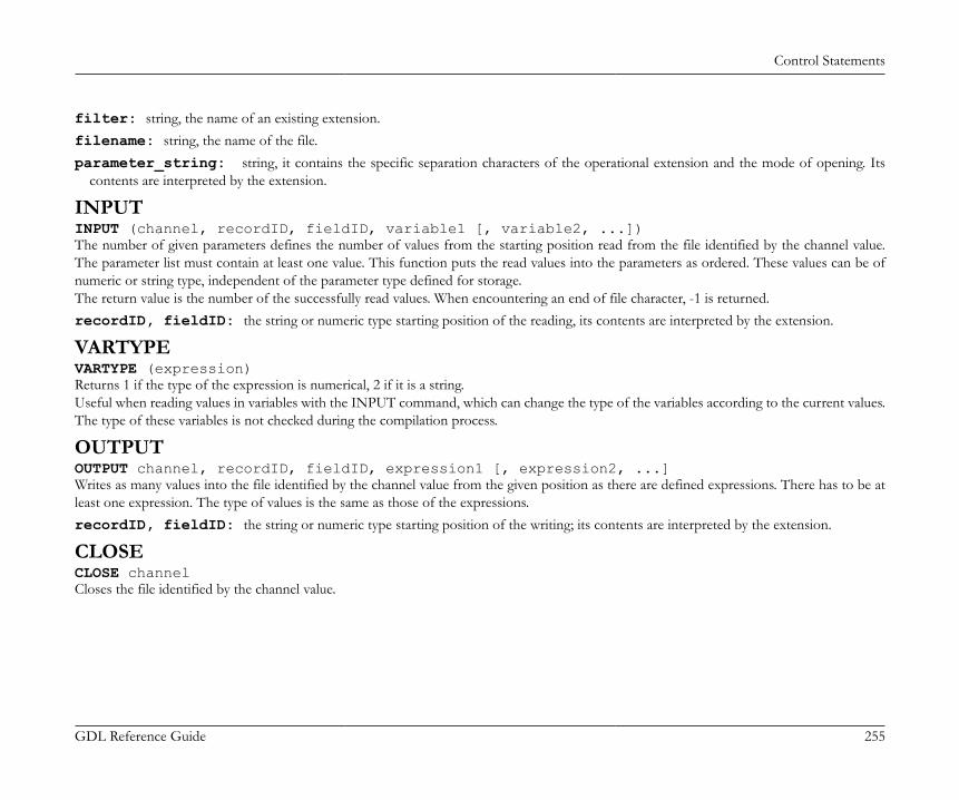
Control Statements
GDL Reference Guide 255
filter: string, the name of an existing extension.filename: string, the name of the file.parameter_string: string, it contains the specific separation characters of the operational extension and the mode of opening. Its
contents are interpreted by the extension.
INPUTINPUT (channel, recordID, fieldID, variable1 [, variable2, ...])The number of given parameters defines the number of values from the starting position read from the file identified by the channel value.The parameter list must contain at least one value. This function puts the read values into the parameters as ordered. These values can be ofnumeric or string type, independent of the parameter type defined for storage.The return value is the number of the successfully read values. When encountering an end of file character, -1 is returned.recordID, fieldID: the string or numeric type starting position of the reading, its contents are interpreted by the extension.
VARTYPEVARTYPE (expression)Returns 1 if the type of the expression is numerical, 2 if it is a string.Useful when reading values in variables with the INPUT command, which can change the type of the variables according to the current values.The type of these variables is not checked during the compilation process.
OUTPUTOUTPUT channel, recordID, fieldID, expression1 [, expression2, ...]Writes as many values into the file identified by the channel value from the given position as there are defined expressions. There has to be atleast one expression. The type of values is the same as those of the expressions.recordID, fieldID: the string or numeric type starting position of the writing; its contents are interpreted by the extension.
CLOSECLOSE channelCloses the file identified by the channel value.
Control Statements
GDL Reference Guide 256
USING DETERMINISTIC ADD-ONSThe following keywords allow you to call GDL add-ons which provide a deterministic function, i.e. the result of a given operation dependson the specified parameters only. This process necessarily involves using special Add-On extensions. For example polygon operations can beexecuted via the PolyOperations add-on. Add-Ons for other operations can be developed by third parties.See also the section called “Polygon Operations Extension”.
INITADDONSCOPEINITADDONSCOPE (extension, parameter_string1, parameter_string2)Opens a channel as directed. Its return value is a positive integer that will identify the specific connection. This value, the channel number, willbe the connection’s reference number in succeeding instances.extension: string, the name of an existing extension.parameter_string1: string, its contents are interpreted by the extension.parameter_string2: string, its contents are interpreted by the extension.
PREPAREFUNCTIONPREPAREFUNCTION channel, function_name, expression1 [, expression2, ...]Sets some values in the add-on as a preparation step for calling a later function.function_name: the string or numeric identifier of the function to be called; its contents are interpreted by the extension.expression: parameters to be passed for the preparation step.
CALLFUNCTIONCALLFUNCTION (channel, function_name, parameter, variable1 [, variable2, ...])The function named function_name in the add-on specified by channel is called. The parameter list must contain at least one value. This functionputs the returned values into the parameters as ordered. The return value is the number of the successfully set values.channel: channel value, used to identify the connection.function_name: the string or numeric identifier of the function to be called; its contents are interpreted by the extension.parameter: input parameter; its contents are interpreted by the extension.variablei: output parameter.
CLOSEADDONSCOPECLOSEADDONSCOPE channel
Control Statements
GDL Reference Guide 257
Closes the connection identified by the channel value.
Miscellaneous
GDL Reference Guide 258
MISCELLANEOUSGDL can also handle a number of operations on external files through special Add-On applications. The commands used to achieve this are described in this chapterand illustrated with an example.
GLOBAL VARIABLESThe global variables make it possible to store special values of the model. This allows you to access geometric information about the environmentof the GDL macro. For example, you can access the wall parameters when defining a window which has to fit into the wall. Global variablesare not stacked during macro calls.For doors, windows, labels and property library parts there is one more possibility to communicate with ArchiCAD through fix named, optionalparameters. These parameters, if present on the library part’s parameter list, are set by ArchiCAD. See the list of fix named parameters and more detailsin the Basic Library documentation http://www.graphisoft.com/support/developer/documentation/LibraryDevDoc/16/.
General environment informationGLOB_SCRIPT_TYPE type of current script
1-properties script, 2-2D script, 3-3D script, 4-user interface script, 5-parameters script, 6-master script, 7-forward migration script, 8-backward migration script
GLOB_CONTEXT context of appearance
1-library part editor, 2-floor plan, 3-3D view, 4-section/elevation, 5-settings dialog, 6-list, 7 - detail drawing, 8 - layout, 22 - editing feedback mode from the floor plan, 23 - editingfeedback mode from a 3Dview, 24 - editing feedback mode from a section/elevation, 28 - editing feedback mode from a layout, 43 - generating as an operator from a 3D view, 44- generating as an operator from a section/elevation, 46 - generating as an operator from a list
GLOB_SCALE drawing scale
according to the current window
GLOB_DRAWING_BGD_PEN pen of the drawing background color
the best matching (printable) pen from the current palette to the background color of the current window
GLOB_NORTH_DIR project North direction
relative to the default project coordinate system according to the settings made in the Project Location dialog
Miscellaneous
GDL Reference Guide 259
GLOB_PROJECT_LONGITUDE project longitude
GLOB_PROJECT_LATITUDE project latitude
GLOB_PROJECT_ALTITUDE project altitude
the geographical coordinates of the project origin according to the settings specified in the Project Location dialog
GLOB_PROJECT_DATE project date
array of the following six values: 1 - year, 2 - month, 3 - day, 4 - hour, 5 - minute, 6 - second. This variable contains the project's current date and is set only in relevant views(in other cases all values are set to 0).
GLOB_WORLD_ORIGO_OFFSET_X
GLOB_WORLD_ORIGO_OFFSET_Y
Position of the project origin relative to the world origin. See Illustrating the usage of the GLOB_WORLD_ORIGO_... globals.
GLOB_MODPAR_NAME name of the last modified parameter
in the settings dialog or library part editor, including parameters modified through editable hotspots.
GLOB_UI_BUTTON_ID id of the button pushed on the UI page
or 0, if the last action was not the push of a button with id.
GLOB_CUTPLANES_INFO
array of 4 length values: 1 - cutplane height, 2 - cutplane top level, 3 - cutplane bottom level, 4 - absolute display limit, in the library part’s local coordinate system. See details inArchiCAD Set Floor Plan Cutplane dialog.
GLOB_STRUCTURE_DISPLAY structure display detail
informs about the partial structure display option settings (integer): 0 - entire structure, 1 - core only, 2 - without finishes
Story informationGLOB_HSTORY_ELEV elevation of the home story
home story is the one the object is placed on
GLOB_HSTORY_HEIGHT height of the home story
home story is the one the object is placed on
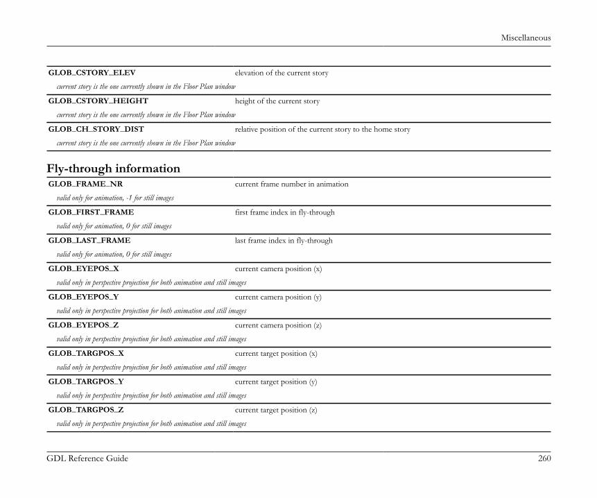
Miscellaneous
GDL Reference Guide 260
GLOB_CSTORY_ELEV elevation of the current story
current story is the one currently shown in the Floor Plan window
GLOB_CSTORY_HEIGHT height of the current story
current story is the one currently shown in the Floor Plan window
GLOB_CH_STORY_DIST relative position of the current story to the home story
current story is the one currently shown in the Floor Plan window
Fly-through informationGLOB_FRAME_NR current frame number in animation
valid only for animation, -1 for still images
GLOB_FIRST_FRAME first frame index in fly-through
valid only for animation, 0 for still images
GLOB_LAST_FRAME last frame index in fly-through
valid only for animation, 0 for still images
GLOB_EYEPOS_X current camera position (x)
valid only in perspective projection for both animation and still images
GLOB_EYEPOS_Y current camera position (y)
valid only in perspective projection for both animation and still images
GLOB_EYEPOS_Z current camera position (z)
valid only in perspective projection for both animation and still images
GLOB_TARGPOS_X current target position (x)
valid only in perspective projection for both animation and still images
GLOB_TARGPOS_Y current target position (y)
valid only in perspective projection for both animation and still images
GLOB_TARGPOS_Z current target position (z)
valid only in perspective projection for both animation and still images
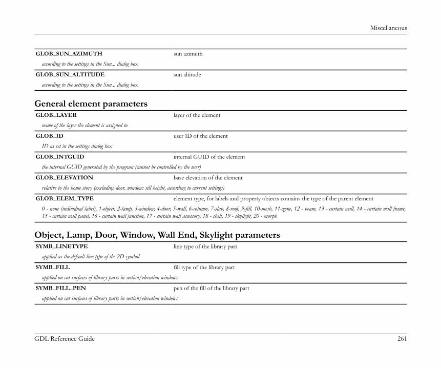
Miscellaneous
GDL Reference Guide 261
GLOB_SUN_AZIMUTH sun azimuth
according to the settings in the Sun... dialog box
GLOB_SUN_ALTITUDE sun altitude
according to the settings in the Sun... dialog box
General element parametersGLOB_LAYER layer of the element
name of the layer the element is assigned to
GLOB_ID user ID of the element
ID as set in the settings dialog box
GLOB_INTGUID internal GUID of the element
the internal GUID generated by the program (cannot be controlled by the user)
GLOB_ELEVATION base elevation of the element
relative to the home story (excluding door, window: sill height, according to current settings)
GLOB_ELEM_TYPE element type, for labels and property objects contains the type of the parent element
0 - none (individual label), 1-object, 2-lamp, 3-window, 4-door, 5-wall, 6-column, 7-slab, 8-roof, 9-fill, 10-mesh, 11-zone, 12 - beam, 13 - curtain wall, 14 - curtain wall frame,15 - curtain wall panel, 16 - curtain wall junction, 17 - curtain wall accessory, 18 - shell, 19 - skylight, 20 - morph
Object, Lamp, Door, Window, Wall End, Skylight parametersSYMB_LINETYPE line type of the library part
applied as the default line type of the 2D symbol
SYMB_FILL fill type of the library part
applied on cut surfaces of library parts in section/elevation windows
SYMB_FILL_PEN pen of the fill of the library part
applied on cut surfaces of library parts in section/elevation windows
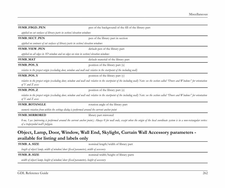
Miscellaneous
GDL Reference Guide 262
SYMB_FBGD_PEN pen of the background of the fill of the library part
applied on cut surfaces of library parts in section/elevation windows
SYMB_SECT_PEN pen of the library part in section
applied on contours of cut surfaces of library parts in section/elevation windows
SYMB_VIEW_PEN default pen of the library part
applied on all edges in 3D window and on edges on view in section/elevation windows
SYMB_MAT default material of the library part
SYMB_POS_X position of the library part (x)
relative to the project origin (excluding door, window and wall end: relative to the startpoint of the including wall)
SYMB_POS_Y position of the library part (y)
relative to the project origin (excluding door, window and wall end: relative to the startpoint of the including wall) Note: see the section called “Doors and Windows” for orientationof Y and Z axes
SYMB_POS_Z position of the library part (z)
relative to the project origin (excluding door, window and wall end: relative to the startpoint of the including wall) Note: see the section called “Doors and Windows” for orientationof Y and Z axes
SYMB_ROTANGLE rotation angle of the library part
numeric rotation from within the settings dialog is performed around the current anchor point
SYMB_MIRRORED library part mirrored
0-no, 1-yes (mirroring is performed around the current anchor point.) Always 0 for wall ends, except when the origin of the local coordinate system is in a non-rectangular vertexof a trapezoidal wall’s polygon.
Object, Lamp, Door, Window, Wall End, Skylight, Curtain Wall Accessory parameters -available for listing and labels onlySYMB_A_SIZE nominal length/width of library part
length of object/lamp, width of window/door (fixed parameter), width of accessory
SYMB_B_SIZE nominal width/height of library parts
width of object/lamp, height of window/door (fixed parameter), height of accessory
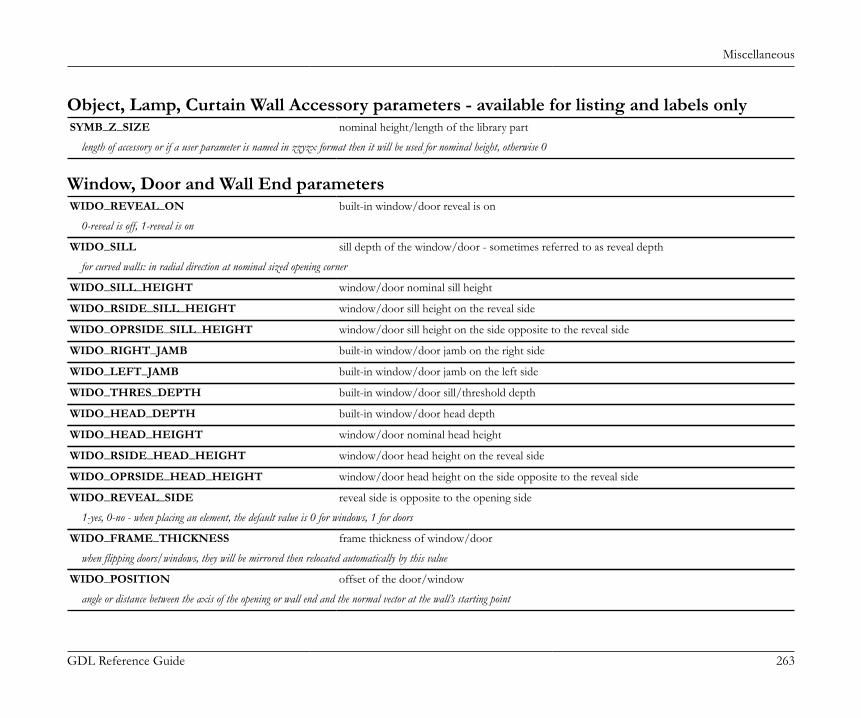
Miscellaneous
GDL Reference Guide 263
Object, Lamp, Curtain Wall Accessory parameters - available for listing and labels onlySYMB_Z_SIZE nominal height/length of the library part
length of accessory or if a user parameter is named in zzyzx format then it will be used for nominal height, otherwise 0
Window, Door and Wall End parametersWIDO_REVEAL_ON built-in window/door reveal is on
0-reveal is off, 1-reveal is on
WIDO_SILL sill depth of the window/door - sometimes referred to as reveal depth
for curved walls: in radial direction at nominal sized opening corner
WIDO_SILL_HEIGHT window/door nominal sill height
WIDO_RSIDE_SILL_HEIGHT window/door sill height on the reveal side
WIDO_OPRSIDE_SILL_HEIGHT window/door sill height on the side opposite to the reveal side
WIDO_RIGHT_JAMB built-in window/door jamb on the right side
WIDO_LEFT_JAMB built-in window/door jamb on the left side
WIDO_THRES_DEPTH built-in window/door sill/threshold depth
WIDO_HEAD_DEPTH built-in window/door head depth
WIDO_HEAD_HEIGHT window/door nominal head height
WIDO_RSIDE_HEAD_HEIGHT window/door head height on the reveal side
WIDO_OPRSIDE_HEAD_HEIGHT window/door head height on the side opposite to the reveal side
WIDO_REVEAL_SIDE reveal side is opposite to the opening side
1-yes, 0-no - when placing an element, the default value is 0 for windows, 1 for doors
WIDO_FRAME_THICKNESS frame thickness of window/door
when flipping doors/windows, they will be mirrored then relocated automatically by this value
WIDO_POSITION offset of the door/window
angle or distance between the axis of the opening or wall end and the normal vector at the wall’s starting point
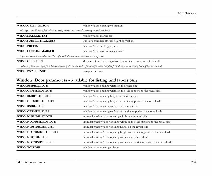
Miscellaneous
GDL Reference Guide 264
WIDO_ORIENTATION window/door opening orientation
left/right - it will work fine only if the door/window was created according to local standards
WIDO_MARKER_TXT window/door marker text
WIDO_SUBFL_THICKNESS subfloor thickness (for sill height correction)
WIDO_PREFIX window/door sill height prefix
WIDO_CUSTOM_MARKER window/door custom marker switch
1-parameters can be used in the 2D script while the automatic dimension is not present
WIDO_ORIG_DIST distance of the local origin from the center of curvature of the wall
distance of the local origin from the centerpoint of the curved wall, 0 for straight walls. Negative for wall ends at the ending point of the curved wall.
WIDO_PWALL_INSET parapet wall inset
Window, Door parameters - available for listing and labels onlyWIDO_RSIDE_WIDTH window/door opening width on the reveal side
WIDO_OPRSIDE_WIDTH window/door opening width on the side opposite to the reveal side
WIDO_RSIDE_HEIGHT window/door opening height on the reveal side
WIDO_OPRSIDE_HEIGHT window/door opening height on the side opposite to the reveal side
WIDO_RSIDE_SURF window/door opening surface on the reveal side
WIDO_OPRSIDE_SURF window/door opening surface on the side opposite to the reveal side
WIDO_N_RSIDE_WIDTH nominal window/door opening width on the reveal side
WIDO_N_OPRSIDE_WIDTH nominal window/door opening width on the side opposite to the reveal side
WIDO_N_RSIDE_HEIGHT nominal window/door opening height on the reveal side
WIDO_N_OPRSIDE_HEIGHT nominal window/door opening height on the side opposite to the reveal side
WIDO_N_RSIDE_SURF nominal window/door opening surface on the reveal side
WIDO_N_OPRSIDE_SURF nominal window/door opening surface on the side opposite to the reveal side
WIDO_VOLUME window/door opening volume
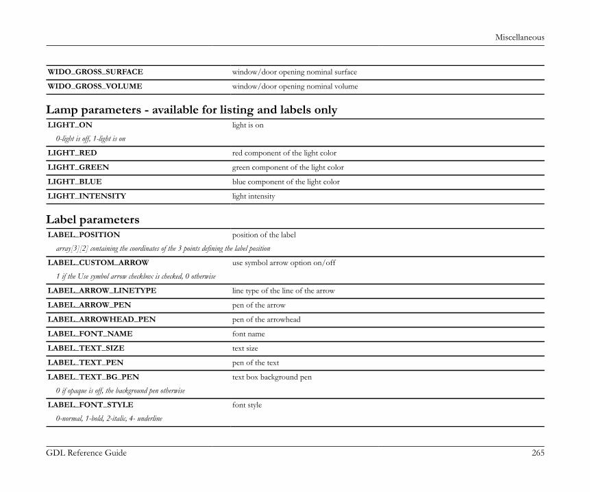
Miscellaneous
GDL Reference Guide 265
WIDO_GROSS_SURFACE window/door opening nominal surface
WIDO_GROSS_VOLUME window/door opening nominal volume
Lamp parameters - available for listing and labels onlyLIGHT_ON light is on
0-light is off, 1-light is on
LIGHT_RED red component of the light color
LIGHT_GREEN green component of the light color
LIGHT_BLUE blue component of the light color
LIGHT_INTENSITY light intensity
Label parametersLABEL_POSITION position of the label
array[3][2] containing the coordinates of the 3 points defining the label position
LABEL_CUSTOM_ARROW use symbol arrow option on/off
1 if the Use symbol arrow checkbox is checked, 0 otherwise
LABEL_ARROW_LINETYPE line type of the line of the arrow
LABEL_ARROW_PEN pen of the arrow
LABEL_ARROWHEAD_PEN pen of the arrowhead
LABEL_FONT_NAME font name
LABEL_TEXT_SIZE text size
LABEL_TEXT_PEN pen of the text
LABEL_TEXT_BG_PEN text box background pen
0 if opaque is off, the background pen otherwise
LABEL_FONT_STYLE font style
0-normal, 1-bold, 2-italic, 4- underline
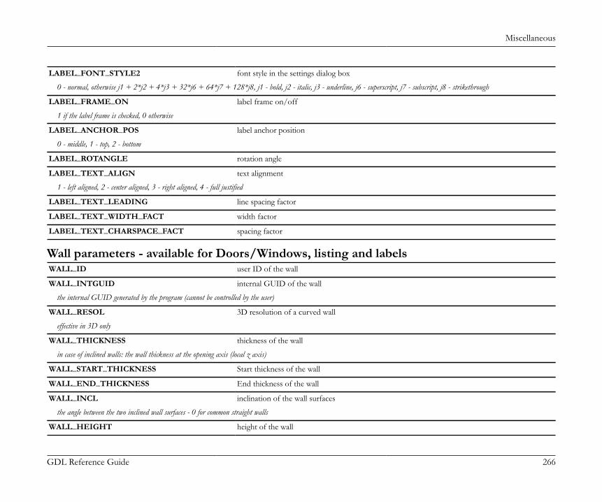
Miscellaneous
GDL Reference Guide 266
LABEL_FONT_STYLE2 font style in the settings dialog box
0 - normal, otherwise j1 + 2*j2 + 4*j3 + 32*j6 + 64*j7 + 128*j8, j1 - bold, j2 - italic, j3 - underline, j6 - superscript, j7 - subscript, j8 - strikethrough
LABEL_FRAME_ON label frame on/off
1 if the label frame is checked, 0 otherwise
LABEL_ANCHOR_POS label anchor position
0 - middle, 1 - top, 2 - bottom
LABEL_ROTANGLE rotation angle
LABEL_TEXT_ALIGN text alignment
1 - left aligned, 2 - center aligned, 3 - right aligned, 4 - full justified
LABEL_TEXT_LEADING line spacing factor
LABEL_TEXT_WIDTH_FACT width factor
LABEL_TEXT_CHARSPACE_FACT spacing factor
Wall parameters - available for Doors/Windows, listing and labelsWALL_ID user ID of the wall
WALL_INTGUID internal GUID of the wall
the internal GUID generated by the program (cannot be controlled by the user)
WALL_RESOL 3D resolution of a curved wall
effective in 3D only
WALL_THICKNESS thickness of the wall
in case of inclined walls: the wall thickness at the opening axis (local z axis)
WALL_START_THICKNESS Start thickness of the wall
WALL_END_THICKNESS End thickness of the wall
WALL_INCL inclination of the wall surfaces
the angle between the two inclined wall surfaces - 0 for common straight walls
WALL_HEIGHT height of the wall
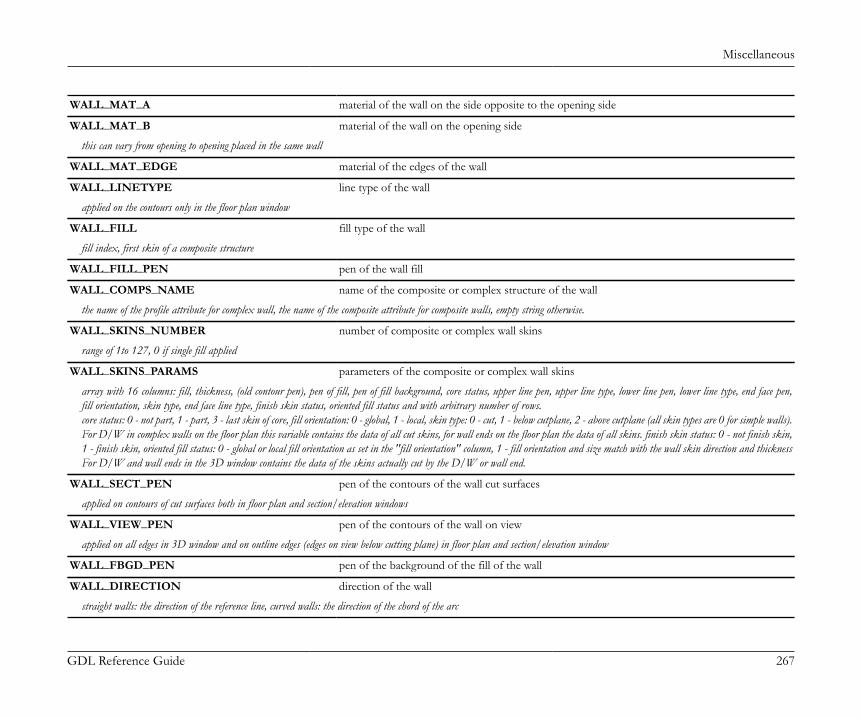
Miscellaneous
GDL Reference Guide 267
WALL_MAT_A material of the wall on the side opposite to the opening side
WALL_MAT_B material of the wall on the opening side
this can vary from opening to opening placed in the same wall
WALL_MAT_EDGE material of the edges of the wall
WALL_LINETYPE line type of the wall
applied on the contours only in the floor plan window
WALL_FILL fill type of the wall
fill index, first skin of a composite structure
WALL_FILL_PEN pen of the wall fill
WALL_COMPS_NAME name of the composite or complex structure of the wall
the name of the profile attribute for complex wall, the name of the composite attribute for composite walls, empty string otherwise.
WALL_SKINS_NUMBER number of composite or complex wall skins
range of 1to 127, 0 if single fill applied
WALL_SKINS_PARAMS parameters of the composite or complex wall skins
array with 16 columns: fill, thickness, (old contour pen), pen of fill, pen of fill background, core status, upper line pen, upper line type, lower line pen, lower line type, end face pen,fill orientation, skin type, end face line type, finish skin status, oriented fill status and with arbitrary number of rows.core status: 0 - not part, 1 - part, 3 - last skin of core, fill orientation: 0 - global, 1 - local, skin type: 0 - cut, 1 - below cutplane, 2 - above cutplane (all skin types are 0 for simple walls).For D/W in complex walls on the floor plan this variable contains the data of all cut skins, for wall ends on the floor plan the data of all skins. finish skin status: 0 - not finish skin,1 - finish skin, oriented fill status: 0 - global or local fill orientation as set in the "fill orientation" column, 1 - fill orientation and size match with the wall skin direction and thicknessFor D/W and wall ends in the 3D window contains the data of the skins actually cut by the D/W or wall end.
WALL_SECT_PEN pen of the contours of the wall cut surfaces
applied on contours of cut surfaces both in floor plan and section/elevation windows
WALL_VIEW_PEN pen of the contours of the wall on view
applied on all edges in 3D window and on outline edges (edges on view below cutting plane) in floor plan and section/elevation window
WALL_FBGD_PEN pen of the background of the fill of the wall
WALL_DIRECTION direction of the wall
straight walls: the direction of the reference line, curved walls: the direction of the chord of the arc
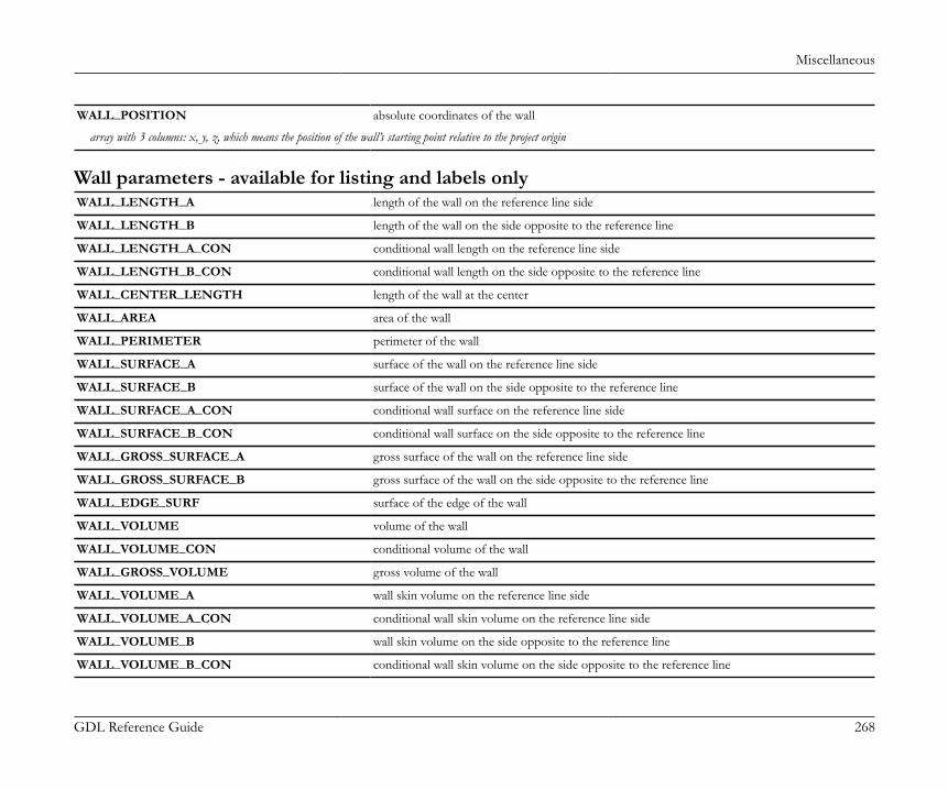
Miscellaneous
GDL Reference Guide 268
WALL_POSITION absolute coordinates of the wall
array with 3 columns: x, y, z, which means the position of the wall’s starting point relative to the project origin
Wall parameters - available for listing and labels onlyWALL_LENGTH_A length of the wall on the reference line side
WALL_LENGTH_B length of the wall on the side opposite to the reference line
WALL_LENGTH_A_CON conditional wall length on the reference line side
WALL_LENGTH_B_CON conditional wall length on the side opposite to the reference line
WALL_CENTER_LENGTH length of the wall at the center
WALL_AREA area of the wall
WALL_PERIMETER perimeter of the wall
WALL_SURFACE_A surface of the wall on the reference line side
WALL_SURFACE_B surface of the wall on the side opposite to the reference line
WALL_SURFACE_A_CON conditional wall surface on the reference line side
WALL_SURFACE_B_CON conditional wall surface on the side opposite to the reference line
WALL_GROSS_SURFACE_A gross surface of the wall on the reference line side
WALL_GROSS_SURFACE_B gross surface of the wall on the side opposite to the reference line
WALL_EDGE_SURF surface of the edge of the wall
WALL_VOLUME volume of the wall
WALL_VOLUME_CON conditional volume of the wall
WALL_GROSS_VOLUME gross volume of the wall
WALL_VOLUME_A wall skin volume on the reference line side
WALL_VOLUME_A_CON conditional wall skin volume on the reference line side
WALL_VOLUME_B wall skin volume on the side opposite to the reference line
WALL_VOLUME_B_CON conditional wall skin volume on the side opposite to the reference line
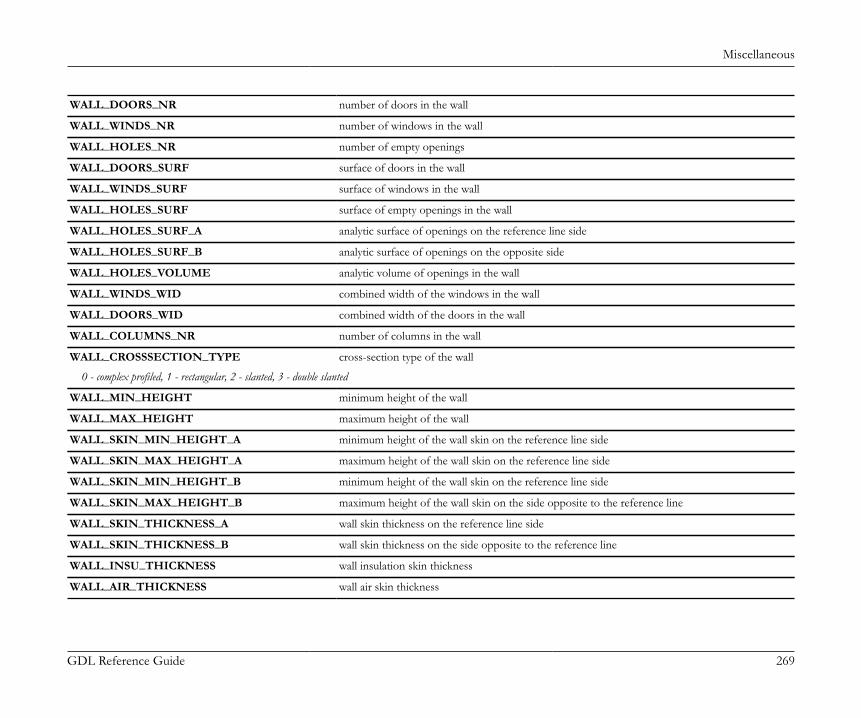
Miscellaneous
GDL Reference Guide 269
WALL_DOORS_NR number of doors in the wall
WALL_WINDS_NR number of windows in the wall
WALL_HOLES_NR number of empty openings
WALL_DOORS_SURF surface of doors in the wall
WALL_WINDS_SURF surface of windows in the wall
WALL_HOLES_SURF surface of empty openings in the wall
WALL_HOLES_SURF_A analytic surface of openings on the reference line side
WALL_HOLES_SURF_B analytic surface of openings on the opposite side
WALL_HOLES_VOLUME analytic volume of openings in the wall
WALL_WINDS_WID combined width of the windows in the wall
WALL_DOORS_WID combined width of the doors in the wall
WALL_COLUMNS_NR number of columns in the wall
WALL_CROSSSECTION_TYPE cross-section type of the wall
0 - complex profiled, 1 - rectangular, 2 - slanted, 3 - double slanted
WALL_MIN_HEIGHT minimum height of the wall
WALL_MAX_HEIGHT maximum height of the wall
WALL_SKIN_MIN_HEIGHT_A minimum height of the wall skin on the reference line side
WALL_SKIN_MAX_HEIGHT_A maximum height of the wall skin on the reference line side
WALL_SKIN_MIN_HEIGHT_B minimum height of the wall skin on the reference line side
WALL_SKIN_MAX_HEIGHT_B maximum height of the wall skin on the side opposite to the reference line
WALL_SKIN_THICKNESS_A wall skin thickness on the reference line side
WALL_SKIN_THICKNESS_B wall skin thickness on the side opposite to the reference line
WALL_INSU_THICKNESS wall insulation skin thickness
WALL_AIR_THICKNESS wall air skin thickness
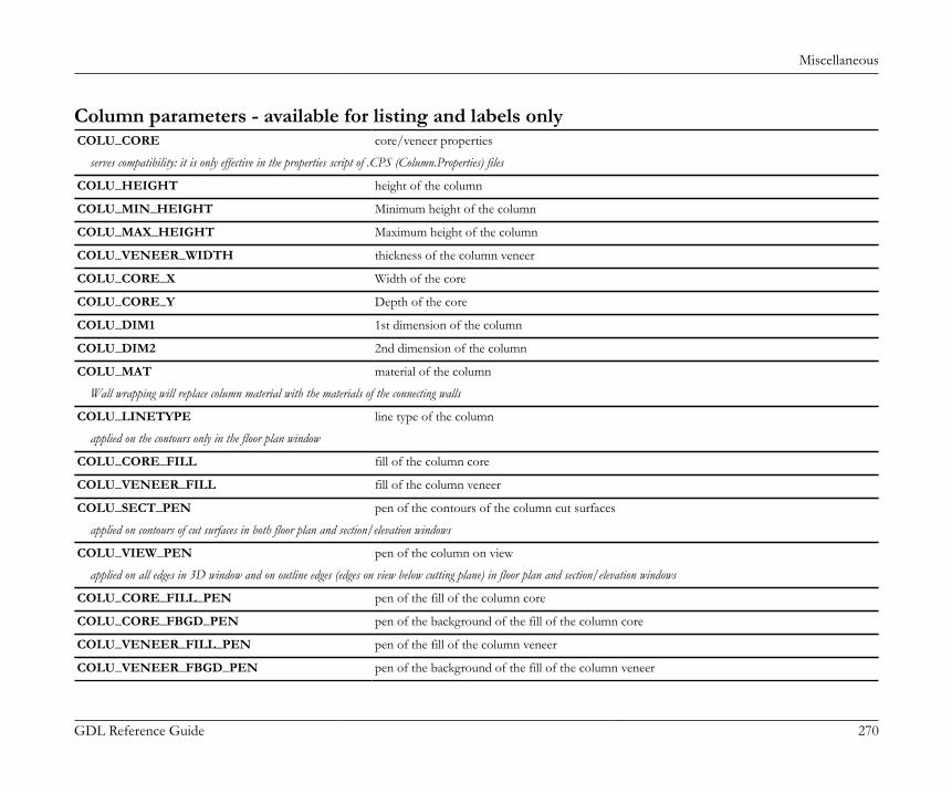
Miscellaneous
GDL Reference Guide 270
Column parameters - available for listing and labels onlyCOLU_CORE core/veneer properties
serves compatibility: it is only effective in the properties script of .CPS (Column.Properties) files
COLU_HEIGHT height of the column
COLU_MIN_HEIGHT Minimum height of the column
COLU_MAX_HEIGHT Maximum height of the column
COLU_VENEER_WIDTH thickness of the column veneer
COLU_CORE_X Width of the core
COLU_CORE_Y Depth of the core
COLU_DIM1 1st dimension of the column
COLU_DIM2 2nd dimension of the column
COLU_MAT material of the column
Wall wrapping will replace column material with the materials of the connecting walls
COLU_LINETYPE line type of the column
applied on the contours only in the floor plan window
COLU_CORE_FILL fill of the column core
COLU_VENEER_FILL fill of the column veneer
COLU_SECT_PEN pen of the contours of the column cut surfaces
applied on contours of cut surfaces in both floor plan and section/elevation windows
COLU_VIEW_PEN pen of the column on view
applied on all edges in 3D window and on outline edges (edges on view below cutting plane) in floor plan and section/elevation windows
COLU_CORE_FILL_PEN pen of the fill of the column core
COLU_CORE_FBGD_PEN pen of the background of the fill of the column core
COLU_VENEER_FILL_PEN pen of the fill of the column veneer
COLU_VENEER_FBGD_PEN pen of the background of the fill of the column veneer
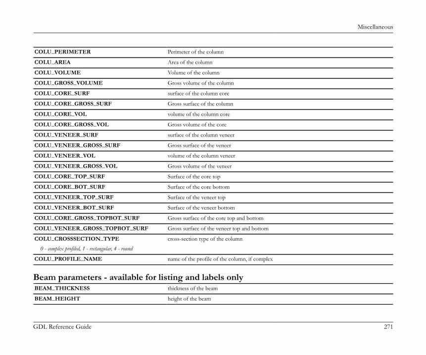
Miscellaneous
GDL Reference Guide 271
COLU_PERIMETER Perimeter of the column
COLU_AREA Area of the column
COLU_VOLUME Volume of the column
COLU_GROSS_VOLUME Gross volume of the column
COLU_CORE_SURF surface of the column core
COLU_CORE_GROSS_SURF Gross surface of the column
COLU_CORE_VOL volume of the column core
COLU_CORE_GROSS_VOL Gross volume of the core
COLU_VENEER_SURF surface of the column veneer
COLU_VENEER_GROSS_SURF Gross surface of the veneer
COLU_VENEER_VOL volume of the column veneer
COLU_VENEER_GROSS_VOL Gross volume of the veneer
COLU_CORE_TOP_SURF Surface of the core top
COLU_CORE_BOT_SURF Surface of the core bottom
COLU_VENEER_TOP_SURF Surface of the veneer top
COLU_VENEER_BOT_SURF Surface of the veneer bottom
COLU_CORE_GROSS_TOPBOT_SURF Gross surface of the core top and bottom
COLU_VENEER_GROSS_TOPBOT_SURF Gross surface of the veneer top and bottom
COLU_CROSSSECTION_TYPE cross-section type of the column
0 - complex profiled, 1 - rectangular, 4 - round
COLU_PROFILE_NAME name of the profile of the column, if complex
Beam parameters - available for listing and labels onlyBEAM_THICKNESS thickness of the beam
BEAM_HEIGHT height of the beam
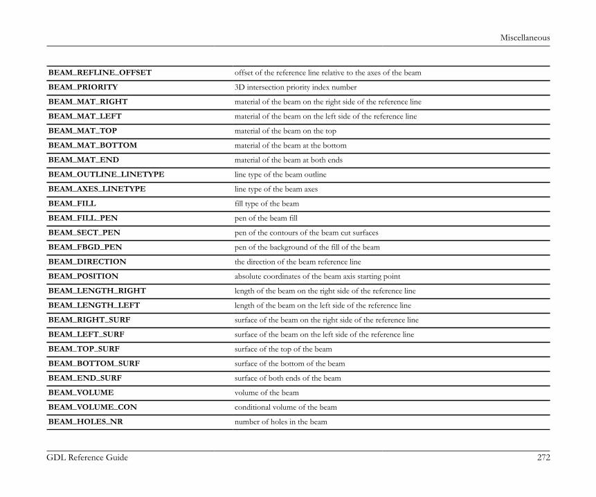
Miscellaneous
GDL Reference Guide 272
BEAM_REFLINE_OFFSET offset of the reference line relative to the axes of the beam
BEAM_PRIORITY 3D intersection priority index number
BEAM_MAT_RIGHT material of the beam on the right side of the reference line
BEAM_MAT_LEFT material of the beam on the left side of the reference line
BEAM_MAT_TOP material of the beam on the top
BEAM_MAT_BOTTOM material of the beam at the bottom
BEAM_MAT_END material of the beam at both ends
BEAM_OUTLINE_LINETYPE line type of the beam outline
BEAM_AXES_LINETYPE line type of the beam axes
BEAM_FILL fill type of the beam
BEAM_FILL_PEN pen of the beam fill
BEAM_SECT_PEN pen of the contours of the beam cut surfaces
BEAM_FBGD_PEN pen of the background of the fill of the beam
BEAM_DIRECTION the direction of the beam reference line
BEAM_POSITION absolute coordinates of the beam axis starting point
BEAM_LENGTH_RIGHT length of the beam on the right side of the reference line
BEAM_LENGTH_LEFT length of the beam on the left side of the reference line
BEAM_RIGHT_SURF surface of the beam on the right side of the reference line
BEAM_LEFT_SURF surface of the beam on the left side of the reference line
BEAM_TOP_SURF surface of the top of the beam
BEAM_BOTTOM_SURF surface of the bottom of the beam
BEAM_END_SURF surface of both ends of the beam
BEAM_VOLUME volume of the beam
BEAM_VOLUME_CON conditional volume of the beam
BEAM_HOLES_NR number of holes in the beam
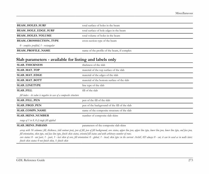
Miscellaneous
GDL Reference Guide 273
BEAM_HOLES_SURF total surface of holes in the beam
BEAM_HOLE_EDGE_SURF total surface of hole edges in the beam
BEAM_HOLES_VOLUME total volume of holes in the beam
BEAM_CROSSSECTION_TYPE cross-section type of the beam
0 - complex profiled, 1 - rectangular
BEAM_PROFILE_NAME name of the profile of the beam, if complex
Slab parameters - available for listing and labels onlySLAB_THICKNESS thickness of the slab
SLAB_MAT_TOP material of the top surface of the slab
SLAB_MAT_EDGE material of the edges of the slab
SLAB_MAT_BOTT material of the bottom surface of the slab
SLAB_LINETYPE line type of the slab
SLAB_FILL fill of the slab
fill index - its value is negative in case of a composite structure
SLAB_FILL_PEN pen of the fill of the slab
SLAB_FBGD_PEN pen of the background of the fill of the slab
SLAB_COMPS_NAME name of the composite structure of the slab
SLAB_SKINS_NUMBER number of composite slab skins
range of 1 to 8, 0 if single fill applied
SLAB_SKINS_PARAMS parameters of the composite slab skins
array with 16 columns: fill, thickness, (old contour pen), pen of fill, pen of fill background, core status, upper line pen, upper line type, lower line pen, lower line type, end face pen,fill orientation, skin type, end face line type, finish skin status, oriented fill status and with arbitrary number of rows.core status: 0 - not part, 1 - part, 3 - last skin of core, fill orientation: 0 - global, 1 - local; skin type: in the current ArchiCAD always 0 - cut, it can be used as in walls later;finish skin status: 0 not finish skin, 1: finish skin
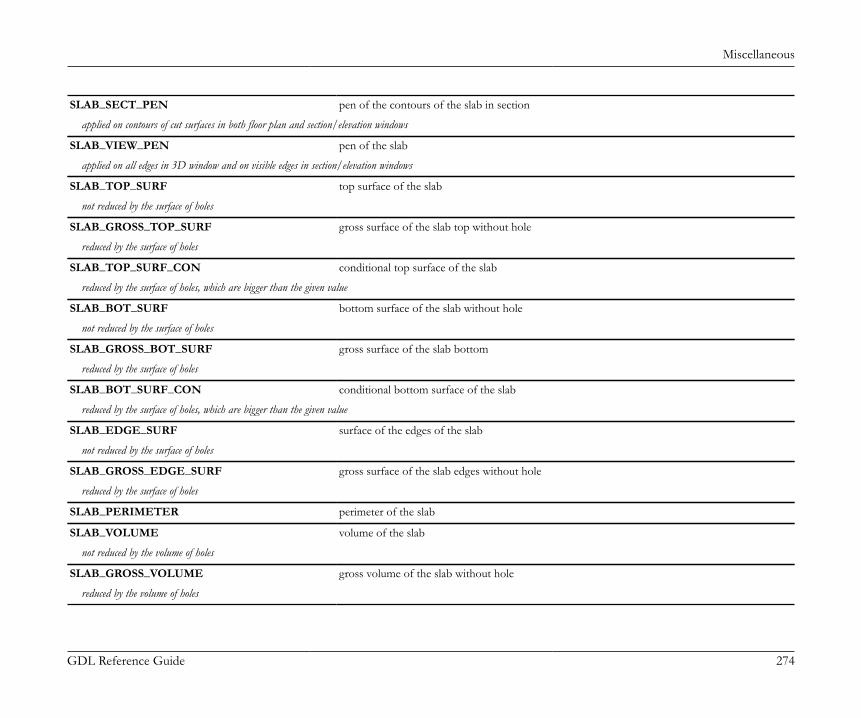
Miscellaneous
GDL Reference Guide 274
SLAB_SECT_PEN pen of the contours of the slab in section
applied on contours of cut surfaces in both floor plan and section/elevation windows
SLAB_VIEW_PEN pen of the slab
applied on all edges in 3D window and on visible edges in section/elevation windows
SLAB_TOP_SURF top surface of the slab
not reduced by the surface of holes
SLAB_GROSS_TOP_SURF gross surface of the slab top without hole
reduced by the surface of holes
SLAB_TOP_SURF_CON conditional top surface of the slab
reduced by the surface of holes, which are bigger than the given value
SLAB_BOT_SURF bottom surface of the slab without hole
not reduced by the surface of holes
SLAB_GROSS_BOT_SURF gross surface of the slab bottom
reduced by the surface of holes
SLAB_BOT_SURF_CON conditional bottom surface of the slab
reduced by the surface of holes, which are bigger than the given value
SLAB_EDGE_SURF surface of the edges of the slab
not reduced by the surface of holes
SLAB_GROSS_EDGE_SURF gross surface of the slab edges without hole
reduced by the surface of holes
SLAB_PERIMETER perimeter of the slab
SLAB_VOLUME volume of the slab
not reduced by the volume of holes
SLAB_GROSS_VOLUME gross volume of the slab without hole
reduced by the volume of holes
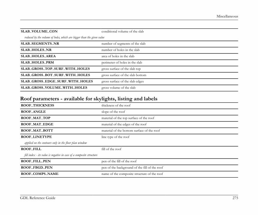
Miscellaneous
GDL Reference Guide 275
SLAB_VOLUME_CON conditional volume of the slab
reduced by the volume of holes, which are bigger than the given value
SLAB_SEGMENTS_NR number of segments of the slab
SLAB_HOLES_NR number of holes in the slab
SLAB_HOLES_AREA area of holes in the slab
SLAB_HOLES_PRM perimeter of holes in the slab
SLAB_GROSS_TOP_SURF_WITH_HOLES gross surface of the slab top
SLAB_GROSS_BOT_SURF_WITH_HOLES gross surface of the slab bottom
SLAB_GROSS_EDGE_SURF_WITH_HOLES gross surface of the slab edges
SLAB_GROSS_VOLUME_WITH_HOLES gross volume of the slab
Roof parameters - available for skylights, listing and labelsROOF_THICKNESS thickness of the roof
ROOF_ANGLE slope of the roof
ROOF_MAT_TOP material of the top surface of the roof
ROOF_MAT_EDGE material of the edges of the roof
ROOF_MAT_BOTT material of the bottom surface of the roof
ROOF_LINETYPE line type of the roof
applied on the contours only in the floor plan window
ROOF_FILL fill of the roof
fill index - its value is negative in case of a composite structure
ROOF_FILL_PEN pen of the fill of the roof
ROOF_FBGD_PEN pen of the background of the fill of the roof
ROOF_COMPS_NAME name of the composite structure of the roof
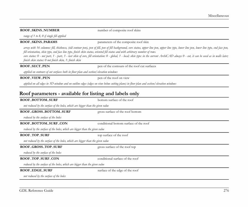
Miscellaneous
GDL Reference Guide 276
ROOF_SKINS_NUMBER number of composite roof skins
range of 1 to 8, 0 if single fill applied
ROOF_SKINS_PARAMS parameters of the composite roof skin
array with 16 columns: fill, thickness, (old contour pen), pen of fill, pen of fill background, core status, upper line pen, upper line type, lower line pen, lower line type, end face pen,fill orientation, skin type, end face line type, finish skin status, oriented fill status and with arbitrary number of rows.core status: 0 - not part, 1 - part, 3 - last skin of core, fill orientation: 0 - global, 1 - local; skin type: in the current ArchiCAD always 0 - cut, it can be used as in walls later;finish skin status: 0 not finish skin, 1: finish skin
ROOF_SECT_PEN pen of the contours of the roof cut surfaces
applied on contours of cut surfaces both in floor plan and section/elevation windows
ROOF_VIEW_PEN pen of the roof on view
applied on all edges in 3D window and on outline edges (edges on view below cutting plane) in floor plan and section/elevation windows
Roof parameters - available for listing and labels onlyROOF_BOTTOM_SURF bottom surface of the roof
not reduced by the surface of the holes, which are bigger than the given value
ROOF_GROSS_BOTTOM_SURF gross surface of the roof bottom
reduced by the surface of the holes
ROOF_BOTTOM_SURF_CON conditional bottom surface of the roof
reduced by the surface of the holes, which are bigger than the given value
ROOF_TOP_SURF top surface of the roof
not reduced by the surface of the holes, which are bigger than the given value
ROOF_GROSS_TOP_SURF gross surface of the roof top
reduced by the surface of the holes
ROOF_TOP_SURF_CON conditional surface of the roof
reduced by the surface of the holes, which are bigger than the given value
ROOF_EDGE_SURF surface of the edge of the roof
not reduced by the surface of the holes
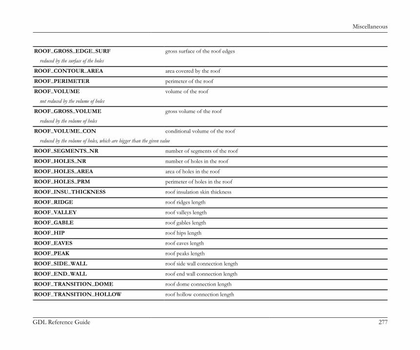
Miscellaneous
GDL Reference Guide 277
ROOF_GROSS_EDGE_SURF gross surface of the roof edges
reduced by the surface of the holes
ROOF_CONTOUR_AREA area covered by the roof
ROOF_PERIMETER perimeter of the roof
ROOF_VOLUME volume of the roof
not reduced by the volume of holes
ROOF_GROSS_VOLUME gross volume of the roof
reduced by the volume of holes
ROOF_VOLUME_CON conditional volume of the roof
reduced by the volume of holes, which are bigger than the given value
ROOF_SEGMENTS_NR number of segments of the roof
ROOF_HOLES_NR number of holes in the roof
ROOF_HOLES_AREA area of holes in the roof
ROOF_HOLES_PRM perimeter of holes in the roof
ROOF_INSU_THICKNESS roof insulation skin thickness
ROOF_RIDGE roof ridges length
ROOF_VALLEY roof valleys length
ROOF_GABLE roof gables length
ROOF_HIP roof hips length
ROOF_EAVES roof eaves length
ROOF_PEAK roof peaks length
ROOF_SIDE_WALL roof side wall connection length
ROOF_END_WALL roof end wall connection length
ROOF_TRANSITION_DOME roof dome connection length
ROOF_TRANSITION_HOLLOW roof hollow connection length
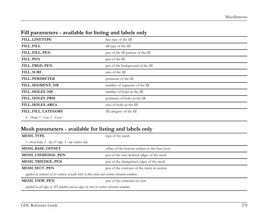
Miscellaneous
GDL Reference Guide 278
Fill parameters - available for listing and labels onlyFILL_LINETYPE line type of the fill
FILL_FILL fill type of the fill
FILL_FILL_PEN pen of the fill pattern of the fill
FILL_PEN pen of the fill
FILL_FBGD_PEN pen of the background of the fill
FILL_SURF area of the fill
FILL_PERIMETER perimeter of the fill
FILL_SEGMENT_NR number of segments of the fill
FILL_HOLES_NR number of holes in the fill
FILL_HOLES_PRM perimeter of holes in the fill
FILL_HOLES_AREA area of holes in the fill
FILL_FILL_CATEGORY fill category of the fill
0 - Draft, 1 - Cut, 2 - Cover
Mesh parameters - available for listing and labels onlyMESH_TYPE type of the mesh
1- closed body, 2 - top & edge, 3 - top surface only
MESH_BASE_OFFSET offset of the bottom surface to the base level
MESH_USEREDGE_PEN pen of the user defined ridges of the mesh
MESH_TRIEDGE_PEN pen of the triangulated edges of the mesh
MESH_SECT_PEN pen of the contours of the mesh in section
applied on contours of cut surfaces of walls both in floor plan and section/elevation windows
MESH_VIEW_PEN pen of the contours on view
applied on all edges in 3D window and on edges on view in section/elevation windows
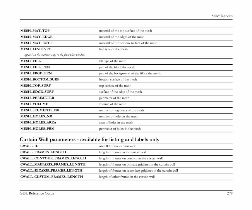
Miscellaneous
GDL Reference Guide 279
MESH_MAT_TOP material of the top surface of the mesh
MESH_MAT_EDGE material of the edges of the mesh
MESH_MAT_BOTT material of the bottom surface of the mesh
MESH_LINETYPE line type of the mesh
applied on the contours only in the floor plan window
MESH_FILL fill type of the mesh
MESH_FILL_PEN pen of the fill of the mesh
MESH_FBGD_PEN pen of the background of the fill of the mesh
MESH_BOTTOM_SURF bottom surface of the mesh
MESH_TOP_SURF top surface of the mesh
MESH_EDGE_SURF surface of the edge of the mesh
MESH_PERIMETER perimeter of the mesh
MESH_VOLUME volume of the mesh
MESH_SEGMENTS_NR number of segments of the mesh
MESH_HOLES_NR number of holes in the mesh
MESH_HOLES_AREA area of holes in the mesh
MESH_HOLES_PRM perimeter of holes in the mesh
Curtain Wall parameters - available for listing and labels onlyCWALL_ID user ID of the curtain wall
CWALL_FRAMES_LENGTH length of frames in the curtain wall
CWALL_CONTOUR_FRAMES_LENGTH length of frames on contour in the curtain wall
CWALL_MAINAXIS_FRAMES_LENGTH length of frames on primary gridlines in the curtain wall
CWALL_SECAXIS_FRAMES_LENGTH length of frames on secondary gridlines in the curtain wall
CWALL_CUSTOM_FRAMES_LENGTH length of other frames in the curtain wall
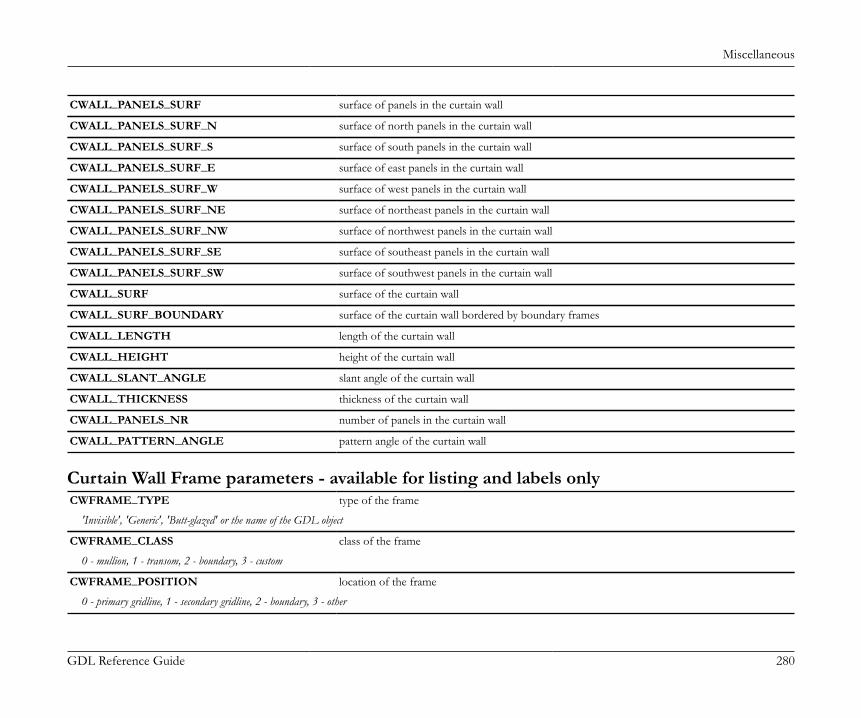
Miscellaneous
GDL Reference Guide 280
CWALL_PANELS_SURF surface of panels in the curtain wall
CWALL_PANELS_SURF_N surface of north panels in the curtain wall
CWALL_PANELS_SURF_S surface of south panels in the curtain wall
CWALL_PANELS_SURF_E surface of east panels in the curtain wall
CWALL_PANELS_SURF_W surface of west panels in the curtain wall
CWALL_PANELS_SURF_NE surface of northeast panels in the curtain wall
CWALL_PANELS_SURF_NW surface of northwest panels in the curtain wall
CWALL_PANELS_SURF_SE surface of southeast panels in the curtain wall
CWALL_PANELS_SURF_SW surface of southwest panels in the curtain wall
CWALL_SURF surface of the curtain wall
CWALL_SURF_BOUNDARY surface of the curtain wall bordered by boundary frames
CWALL_LENGTH length of the curtain wall
CWALL_HEIGHT height of the curtain wall
CWALL_SLANT_ANGLE slant angle of the curtain wall
CWALL_THICKNESS thickness of the curtain wall
CWALL_PANELS_NR number of panels in the curtain wall
CWALL_PATTERN_ANGLE pattern angle of the curtain wall
Curtain Wall Frame parameters - available for listing and labels onlyCWFRAME_TYPE type of the frame
'Invisible', 'Generic', 'Butt-glazed' or the name of the GDL object
CWFRAME_CLASS class of the frame
0 - mullion, 1 - transom, 2 - boundary, 3 - custom
CWFRAME_POSITION location of the frame
0 - primary gridline, 1 - secondary gridline, 2 - boundary, 3 - other
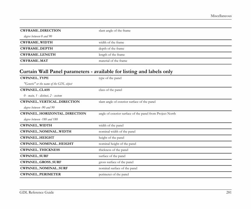
Miscellaneous
GDL Reference Guide 281
CWFRAME_DIRECTION slant angle of the frame
degree between 0 and 90
CWFRAME_WIDTH width of the frame
CWFRAME_DEPTH depth of the frame
CWFRAME_LENGTH length of the frame
CWFRAME_MAT material of the frame
Curtain Wall Panel parameters - available for listing and labels onlyCWPANEL_TYPE type of the panel
"Generic" or the name of the GDL object
CWPANEL_CLASS class of the panel
0 - main, 1 - distinct, 2 - custom
CWPANEL_VERTICAL_DIRECTION slant angle of exterior surface of the panel
degree between -90 and 90
CWPANEL_HORIZONTAL_DIRECTION angle of exterior surface of the panel from Project North
degree between -180 and 180
CWPANEL_WIDTH width of the panel
CWPANEL_NOMINAL_WIDTH nominal width of the panel
CWPANEL_HEIGHT height of the panel
CWPANEL_NOMINAL_HEIGHT nominal height of the panel
CWPANEL_THICKNESS thickness of the panel
CWPANEL_SURF surface of the panel
CWPANEL_GROSS_SURF gross surface of the panel
CWPANEL_NOMINAL_SURF nominal surface of the panel
CWPANEL_PERIMETER perimeter of the panel
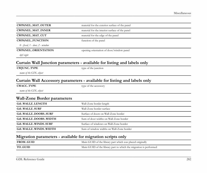
Miscellaneous
GDL Reference Guide 282
CWPANEL_MAT_OUTER material for the exterior surface of the panel
CWPANEL_MAT_INNER material for the interior surface of the panel
CWPANEL_MAT_CUT material for the edge of the panel
CWPANEL_FUNCTION function of the panel
0 - fixed, 1 - door, 2 - window
CWPANEL_ORIENTATION opening orientation of door/window panel
left/right
Curtain Wall Junction parameters - available for listing and labels onlyCWJUNC_TYPE type of the junction
name of the GDL object
Curtain Wall Accessory parameters - available for listing and labels onlyCWACC_TYPE type of the accessory
name of the GDL object
Wall-Zone Border parametersGdl_WALLZ_LENGTH Wall-Zone border length
Gdl_WALLZ_SURF Wall-Zone border surface
Gdl_WALLZ_DOORS_SURF Surface of doors on Wall-Zone border
Gdl_WALLZ_DOORS_WIDTH Sum of door widths on Wall-Zone border
Gdl_WALLZ_WINDS_SURF Surface of windows on Wall-Zone border
Gdl_WALLZ_WINDS_WIDTH Sum of window widths on Wall-Zone border
Migration parameters - available for migration scripts onlyFROM_GUID Main GUID of the library part which was placed originally
TO_GUID Main GUID of the library part to which the migration is performed
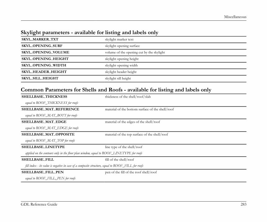
Miscellaneous
GDL Reference Guide 283
Skylight parameters - available for listing and labels onlySKYL_MARKER_TXT skylight marker text
SKYL_OPENING_SURF skylight opening surface
SKYL_OPENING_VOLUME volume of the opening cut by the skylight
SKYL_OPENING_HEIGHT skylight opening height
SKYL_OPENING_WIDTH skylight opening width
SKYL_HEADER_HEIGHT skylight header height
SKYL_SILL_HEIGHT skylight sill height
Common Parameters for Shells and Roofs - available for listing and labels onlySHELLBASE_THICKNESS thickness of the shell/roof/slab
equal to ROOF_THICKNESS for roofs
SHELLBASE_MAT_REFERENCE material of the bottom surface of the shell/roof
equal to ROOF_MAT_BOTT for roofs
SHELLBASE_MAT_EDGE material of the edges of the shell/roof
equal to ROOF_MAT_EDGE for roofs
SHELLBASE_MAT_OPPOSITE material of the top surface of the shell/roof
equal to ROOF_MAT_TOP for roofs
SHELLBASE_LINETYPE line type of the shell/roof
applied on the contours only in the floor plan window, equal to ROOF_LINETYPE for roofs
SHELLBASE_FILL fill of the shell/roof
fill index - its value is negative in case of a composite structure, equal to ROOF_FILL for roofs
SHELLBASE_FILL_PEN pen of the fill of the roof shell/roof
equal to ROOF_FILL_PEN for roofs
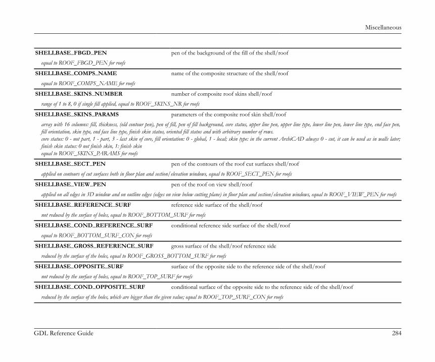
Miscellaneous
GDL Reference Guide 284
SHELLBASE_FBGD_PEN pen of the background of the fill of the shell/roof
equal to ROOF_FBGD_PEN for roofs
SHELLBASE_COMPS_NAME name of the composite structure of the shell/roof
equal to ROOF_COMPS_NAME for roofs
SHELLBASE_SKINS_NUMBER number of composite roof skins shell/roof
range of 1 to 8, 0 if single fill applied, equal to ROOF_SKINS_NR for roofs
SHELLBASE_SKINS_PARAMS parameters of the composite roof skin shell/roof
array with 16 columns: fill, thickness, (old contour pen), pen of fill, pen of fill background, core status, upper line pen, upper line type, lower line pen, lower line type, end face pen,fill orientation, skin type, end face line type, finish skin status, oriented fill status and with arbitrary number of rows.core status: 0 - not part, 1 - part, 3 - last skin of core, fill orientation: 0 - global, 1 - local; skin type: in the current ArchiCAD always 0 - cut, it can be used as in walls later;finish skin status: 0 not finish skin, 1: finish skinequal to ROOF_SKINS_PARAMS for roofs
SHELLBASE_SECT_PEN pen of the contours of the roof cut surfaces shell/roof
applied on contours of cut surfaces both in floor plan and section/elevation windows, equal to ROOF_SECT_PEN for roofs
SHELLBASE_VIEW_PEN pen of the roof on view shell/roof
applied on all edges in 3D window and on outline edges (edges on view below cutting plane) in floor plan and section/elevation windows, equal to ROOF_VIEW_PEN for roofs
SHELLBASE_REFERENCE_SURF reference side surface of the shell/roof
not reduced by the surface of holes, equal to ROOF_BOTTOM_SURF for roofs
SHELLBASE_COND_REFERENCE_SURF conditional reference side surface of the shell/roof
equal to ROOF_BOTTOM_SURF_CON for roofs
SHELLBASE_GROSS_REFERENCE_SURF gross surface of the shell/roof reference side
reduced by the surface of the holes, equal to ROOF_GROSS_BOTTOM_SURF for roofs
SHELLBASE_OPPOSITE_SURF surface of the opposite side to the reference side of the shell/roof
not reduced by the surface of holes, equal to ROOF_TOP_SURF for roofs
SHELLBASE_COND_OPPOSITE_SURF conditional surface of the opposite side to the reference side of the shell/roof
reduced by the surface of the holes, which are bigger than the given value; equal to ROOF_TOP_SURF_CON for roofs
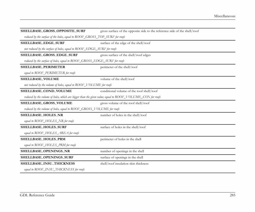
Miscellaneous
GDL Reference Guide 285
SHELLBASE_GROSS_OPPOSITE_SURF gross surface of the opposite side to the reference side of the shell/roof
reduced by the surface of the holes, equal to ROOF_GROSS_TOP_SURF for roofs
SHELLBASE_EDGE_SURF surface of the edge of the shell/roof
not reduced by the surface of holes, equal to ROOF_EDGE_SURF for roofs
SHELLBASE_GROSS_EDGE_SURF gross surface of the shell/roof edges
reduced by the surface of holes, equal to ROOF_GROSS_EDGE_SURF for roofs
SHELLBASE_PERIMETER perimeter of the shell/roof
equal to ROOF_PERIMETER for roofs
SHELLBASE_VOLUME volume of the shell/roof
not reduced by the volume of holes, equal to ROOF_VOLUME for roofs
SHELLBASE_COND_VOLUME conditional volume of the roof shell/roof
reduced by the volume of holes, which are bigger than the given value; equal to ROOF_VOLUME_CON for roofs
SHELLBASE_GROSS_VOLUME gross volume of the roof shell/roof
reduced by the volume of holes, equal to ROOF_GROSS_VOLUME for roofs
SHELLBASE_HOLES_NR number of holes in the shell/roof
equal to ROOF_HOLES_NR for roofs
SHELLBASE_HOLES_SURF surface of holes in the shell/roof
equal to ROOF_HOLES_AREA for roofs
SHELLBASE_HOLES_PRM perimeter of holes in the shell
equal to ROOF_HOLES_PRM for roofs
SHELLBASE_OPENINGS_NR number of openings in the shell
SHELLBASE_OPENINGS_SURF surface of openings in the shell
SHELLBASE_INSU_THICKNESS shell/roof insulation skin thickness
equal to ROOF_INSU_THICKNESS for roofs
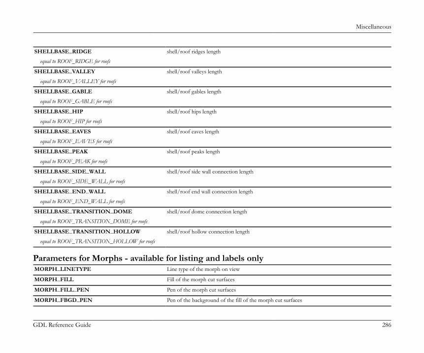
Miscellaneous
GDL Reference Guide 286
SHELLBASE_RIDGE shell/roof ridges length
equal to ROOF_RIDGE for roofs
SHELLBASE_VALLEY shell/roof valleys length
equal to ROOF_VALLEY for roofs
SHELLBASE_GABLE shell/roof gables length
equal to ROOF_GABLE for roofs
SHELLBASE_HIP shell/roof hips length
equal to ROOF_HIP for roofs
SHELLBASE_EAVES shell/roof eaves length
equal to ROOF_EAVES for roofs
SHELLBASE_PEAK shell/roof peaks length
equal to ROOF_PEAK for roofs
SHELLBASE_SIDE_WALL shell/roof side wall connection length
equal to ROOF_SIDE_WALL for roofs
SHELLBASE_END_WALL shell/roof end wall connection length
equal to ROOF_END_WALL for roofs
SHELLBASE_TRANSITION_DOME shell/roof dome connection length
equal to ROOF_TRANSITION_DOME for roofs
SHELLBASE_TRANSITION_HOLLOW shell/roof hollow connection length
equal to ROOF_TRANSITION_HOLLOW for roofs
Parameters for Morphs - available for listing and labels onlyMORPH_LINETYPE Line type of the morph on view
MORPH_FILL Fill of the morph cut surfaces
MORPH_FILL_PEN Pen of the morph cut surfaces
MORPH_FBGD_PEN Pen of the background of the fill of the morph cut surfaces
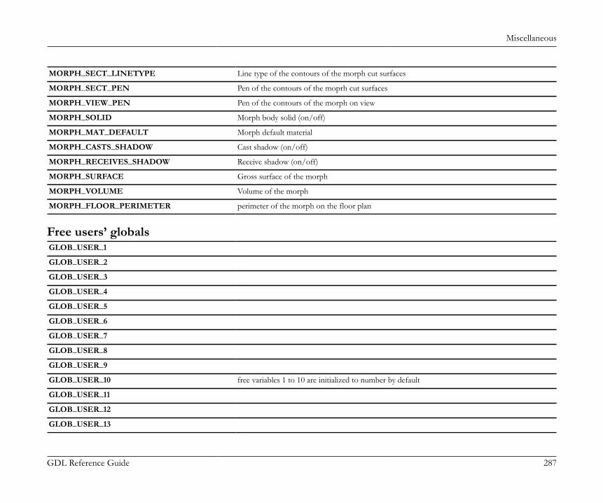
Miscellaneous
GDL Reference Guide 287
MORPH_SECT_LINETYPE Line type of the contours of the morph cut surfaces
MORPH_SECT_PEN Pen of the contours of the moprh cut surfaces
MORPH_VIEW_PEN Pen of the contours of the morph on view
MORPH_SOLID Morph body solid (on/off)
MORPH_MAT_DEFAULT Morph default material
MORPH_CASTS_SHADOW Cast shadow (on/off)
MORPH_RECEIVES_SHADOW Receive shadow (on/off)
MORPH_SURFACE Gross surface of the morph
MORPH_VOLUME Volume of the morph
MORPH_FLOOR_PERIMETER perimeter of the morph on the floor plan
Free users’ globalsGLOB_USER_1
GLOB_USER_2
GLOB_USER_3
GLOB_USER_4
GLOB_USER_5
GLOB_USER_6
GLOB_USER_7
GLOB_USER_8
GLOB_USER_9
GLOB_USER_10 free variables 1 to 10 are initialized to number by default
GLOB_USER_11
GLOB_USER_12
GLOB_USER_13
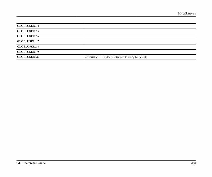
Miscellaneous
GDL Reference Guide 288
GLOB_USER_14
GLOB_USER_15
GLOB_USER_16
GLOB_USER_17
GLOB_USER_18
GLOB_USER_19
GLOB_USER_20 free variables 11 to 20 are initialized to string by default
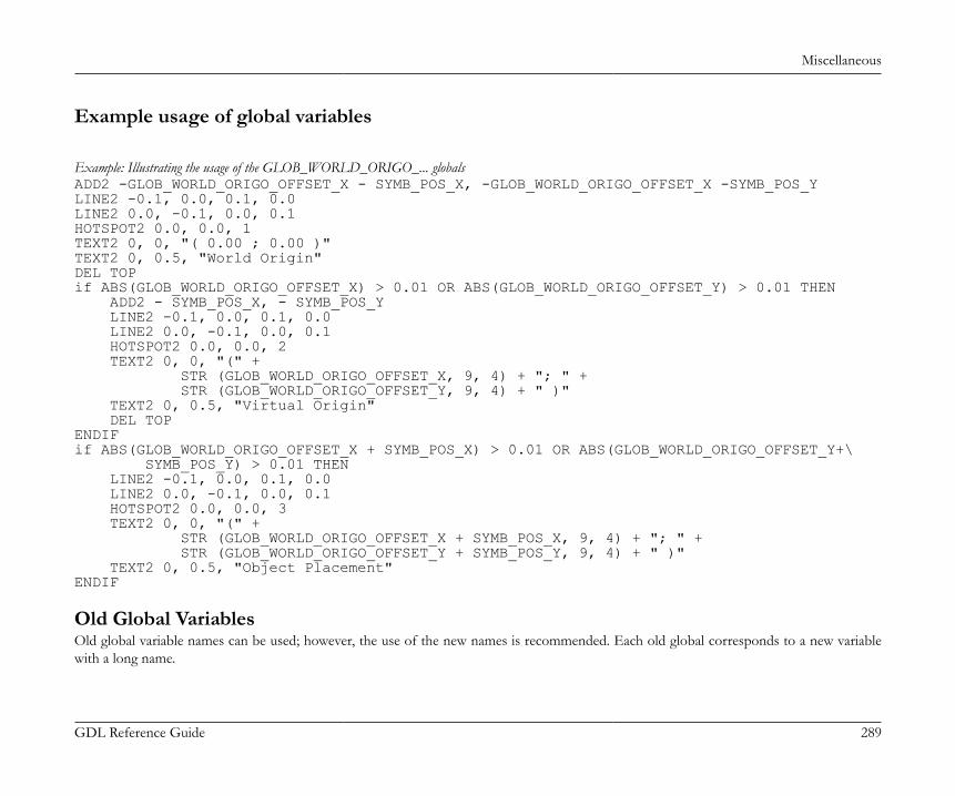
Miscellaneous
GDL Reference Guide 289
Example usage of global variables
Example: Illustrating the usage of the GLOB_WORLD_ORIGO_... globalsADD2 -GLOB_WORLD_ORIGO_OFFSET_X - SYMB_POS_X, -GLOB_WORLD_ORIGO_OFFSET_X -SYMB_POS_YLINE2 -0.1, 0.0, 0.1, 0.0LINE2 0.0, -0.1, 0.0, 0.1HOTSPOT2 0.0, 0.0, 1TEXT2 0, 0, "( 0.00 ; 0.00 )"TEXT2 0, 0.5, "World Origin"DEL TOPif ABS(GLOB_WORLD_ORIGO_OFFSET_X) > 0.01 OR ABS(GLOB_WORLD_ORIGO_OFFSET_Y) > 0.01 THEN ADD2 - SYMB_POS_X, - SYMB_POS_Y LINE2 -0.1, 0.0, 0.1, 0.0 LINE2 0.0, -0.1, 0.0, 0.1 HOTSPOT2 0.0, 0.0, 2 TEXT2 0, 0, "(" + STR (GLOB_WORLD_ORIGO_OFFSET_X, 9, 4) + "; " + STR (GLOB_WORLD_ORIGO_OFFSET_Y, 9, 4) + " )" TEXT2 0, 0.5, "Virtual Origin" DEL TOPENDIFif ABS(GLOB_WORLD_ORIGO_OFFSET_X + SYMB_POS_X) > 0.01 OR ABS(GLOB_WORLD_ORIGO_OFFSET_Y+\ SYMB_POS_Y) > 0.01 THEN LINE2 -0.1, 0.0, 0.1, 0.0 LINE2 0.0, -0.1, 0.0, 0.1 HOTSPOT2 0.0, 0.0, 3 TEXT2 0, 0, "(" + STR (GLOB_WORLD_ORIGO_OFFSET_X + SYMB_POS_X, 9, 4) + "; " + STR (GLOB_WORLD_ORIGO_OFFSET_Y + SYMB_POS_Y, 9, 4) + " )" TEXT2 0, 0.5, "Object Placement"ENDIF
Old Global VariablesOld global variable names can be used; however, the use of the new names is recommended. Each old global corresponds to a new variablewith a long name.
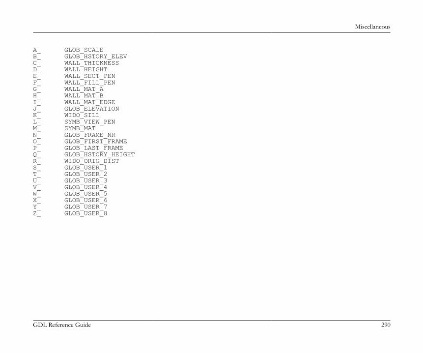
Miscellaneous
GDL Reference Guide 290
A_ GLOB_SCALEB_ GLOB_HSTORY_ELEVC_ WALL_THICKNESSD_ WALL_HEIGHTE_ WALL_SECT_PENF_ WALL_FILL_PENG_ WALL_MAT_AH_ WALL_MAT_BI_ WALL_MAT_EDGEJ_ GLOB_ELEVATIONK_ WIDO_SILLL_ SYMB_VIEW_PENM_ SYMB_MATN_ GLOB_FRAME_NRO_ GLOB_FIRST_FRAMEP_ GLOB_LAST_FRAMEQ_ GLOB_HSTORY_HEIGHTR_ WIDO_ORIG_DISTS_ GLOB_USER_1T_ GLOB_USER_2U_ GLOB_USER_3V_ GLOB_USER_4W_ GLOB_USER_5X_ GLOB_USER_6Y_ GLOB_USER_7Z_ GLOB_USER_8
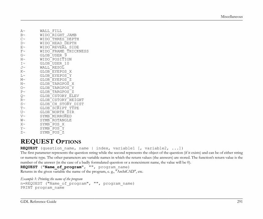
Miscellaneous
GDL Reference Guide 291
A~ WALL_FILLB~ WIDO_RIGHT_JAMBC~ WIDO_THRES_DEPTHD~ WIDO_HEAD_DEPTHE~ WIDO_REVEAL_SIDEF~ WIDO_FRAME_THICKNESSG~ GLOB_USER_9H~ WIDO_POSITIONI~ GLOB_USER_10J~ WALL_RESOLK~ GLOB_EYEPOS_XL~ GLOB_EYEPOS_YM~ GLOB_EYEPOS_ZN~ GLOB_TARGPOS_XO~ GLOB_TARGPOS_YP~ GLOB_TARGPOS_ZQ~ GLOB_CSTORY_ELEVR~ GLOB_CSTORY_HEIGHTS~ GLOB_CH_STORY_DISTT~ GLOB_SCRIPT_TYPEU~ GLOB_NORTH_DIRV~ SYMB_MIRROREDW~ SYMB_ROTANGLEX~ SYMB_POS_XY~ SYMB_POS_YZ~ SYMB_POS_Z
REQUEST OPTIONSREQUEST (question_name, name | index, variable1 [, variable2, ...])The first parameter represents the question string while the second represents the object of the question (if it exists) and can be of either stringor numeric type. The other parameters are variable names in which the return values (the answers) are stored. The function’s return value is thenumber of the answer (in the case of a badly formulated question or a nonexistent name, the value will be 0).REQUEST ("Name_of_program", "", program_name)Returns in the given variable the name of the program, e. g., "ArchiCAD", etc.
Example 1: Printing the name of the programn=REQUEST ("Name_of_program", "", program_name)PRINT program_name
Miscellaneous
GDL Reference Guide 292
REQUEST ("Name_of_macro", "", my_name)REQUEST ("Name_of_main", "", main_name)After executing these function calls, the my_name variable will contain the name of the macro, while main_name will contain the name of themain macro (if it doesn’t exist, empty string).REQUEST ("ID_of_main", "", id_string)For library parts placed on the floor plan, returns the identifier set in the tool’s settings dialog box in the id_string variable (otherwise emptystring).REQUEST ("Name_of_plan", "", name)Returns in the given variable the name of the current project.REQUEST ("Story", "", index, story_name)Returns in the index and story_name variables the index and the name of the current story.REQUEST ("Home_story", "", index, story_name)Returns in the index and story_name variables the index and the name of the home story.REQUEST ("Home_story_of_opening", "", index, story_name)Returns the index and the name of the home story of the opening in the index and story_name variables. The home story is the first story,where the opening is visible. Can be used in scripts of doors, windows, wallends, corner windows and skylights, and in the script of their labelsand markers.REQUEST ("Story_info", expr, nStories, index1, name1, elev1, height1 [, index2, name2, ...])Returns the story information in the given variables: number of stories and story index, name, elevation, height to next successively. If expr is anumerical expression, it means a story index: only the number of stories and the information on the specified story is returned. If expr is a stringexpression, it means that information on all stories is requested. The return value of the function is the number of successfully retrieved values.
Example 2:DIM t[]n = REQUEST ("STORY_INFO", "", nr, t)FOR i = 1 TO nr nr = STR ("%.0m", t [4 * (i - 1) + 1]) name = t [4 * (i - 1) + 2] elevation = STR ("%m", t [4 * (i - 1) + 3]) height = STR ("%m", t [4 * (i - 1) + 4]) TEXT2 0, -i, nr + "," + name + "," + elevation + "," + heightNEXT i
Miscellaneous
GDL Reference Guide 293
REQUEST ("Linear_dimension", "", format_string)REQUEST ("Angular_dimension", "", format_string)REQUEST ("Angular_length_dimension", "" format_string)REQUEST ("Radial_dimension", "", format_string)REQUEST ("Level_dimension", "", format_string)REQUEST ("Elevation_dimension", "", format_string)REQUEST ("Window_door_dimension", "", format_string)REQUEST ("Sill_height_dimension", "", format_string)REQUEST ("Area_dimension", "" format_string)REQUEST ("Calc_length_unit", "", format_string)REQUEST ("Calc_area_unit", "", format_string)REQUEST ("Calc_volume_unit", "", format_string)REQUEST ("Calc_angle_unit", "",format_string)With these requests, you can learn the dimension formats set in the Options/Preferences/Dimensions and Calculation Units dialog boxes.These requests return a format string that can be used as the first parameter in the STR () function.
Example 3:format = "" num = 60.55REQUEST ("Angular_dimension", "",format)!"%.2dd"TEXT2 0, 0, STR (format, num)!60.55
REQUEST ("Clean_intersections", "", state)Returns the state of the Clean Wall & Beam Intersections feature (1 when turned on, 0 when off)REQUEST ("Zone_category", "", name, code)For zones, returns the name and the code string of the current zone category.REQUEST ("Zone_relations", "", category_name, code, name, number [, category_name2, code2, name2, number2])Returns in the given variables the zone category name and code and the name and number of the zone where the library part containing thisrequest is located. For doors and windows, there can be a maximum of two zones. The return value of the request is the number of successfullyretrieved values (0 if the library part is not inside any zone).REQUEST ("Zone_relations_of_owner", "", category_name, code, name, number [, category_name2, code2, name2, number2])Returns in the given variables the category name & code and the zone name & number of the zone where the owner of the object is located.So, it is meaningful, if the library part has owner (door-window labels and door-window markers, etc.). In case of a door label, its owner is the

Miscellaneous
GDL Reference Guide 294
door. For doors and windows, there can be a maximum of two related zones. The return value of the request is the number of successfullyretrieved values (0 if the object has no owner, or its owner is not inside any zone).REQUEST ("Zone_colus_area", "", area)Returns in the area variable the total area of the columns placed in the current zone. Effective only for Zone Stamps. Available only forcompatibility reasons. It is recommended to use quantities set by ArchiCAD in Zone Stamp fix parameters.REQUEST ("Custom_auto_label", "", name)Returns in the name variable the name of the custom auto label of the library part or an empty string if it does not exist.REQUEST ("Rgb_of_material", name, r, g, b)REQUEST ("Rgb_of_pen", penindex, r, g, b)REQUEST ("Pen_of_RGB", "r g b", penindex)Like the REQ() function (but in just one call), returns in the specified variables the value of the r, g, b components of the material and pen,or the index of the pen corresponding to the given RGB values.REQUEST ("Height_of_style", name, height [, descent, leading])Returns in the given variables the total height of the style measured in millimeters (height in meters is height / 1000 * GLOB_SCALE); thedescent (the distance in millimeters from the text base line to the descent line) and the leading (the distance in millimeters from the descentline to the ascent line).REQUEST ("Style_info", name, fontname [, size, anchor, face_or_slant])Returns information in the given variables on the previously defined style (see style parameters at the DEFINE STYLE command). Can be usefulin macros to collect information on the style defined in a main script.REQUEST ("Name_of_material", index, name)Returns in the variable the material name identified by index.REQUEST ("Name_of_fill", index, name)Returns in the name variable the fill name identified by index.REQUEST ("Name_of_line_type", index, name)Returns in the given variable the line name identified by index.REQUEST ("Name_of_style", index, name)Returns in the given variable the name of the style identified by index.If index < 0, it refers to a material, fill, line type or style defined in the GDL script or the MASTER_GDL file. A call of a request with index= 0 returns in the variable the name of the default material or line type. (Empty string for fill and style.)The return value of the request is the number of successfully retrieved values (1 if no error occurred, 0 for error when the index is not valid).REQUEST ("WINDOW_DOOR_SHOW_DIM", "", show)Before 9.0 returns 1 in the show variable if Options/Display Options/Doors & Windows is set to "Show with Dimensions", 0 otherwise. Since9.0 display options were split to separate Door and Window display options, so for compatibility reasons AC checks if the request is used in a
Miscellaneous
GDL Reference Guide 295
Window (or marker of a Window) or a Door (or marker of a Door) and automatically returns the corresponding display option. In other cases(symbol, lamp, label) the Window option is returned. Can be used to hide/show custom dimensions according to the current Display Options.Since 9.0 the "window_show_dim", and the "door_show_dim" separate requests are available.REQUEST ("window_show_dim", "", show)Returns 1 in the show variable if in the Model View Options/Window options the "with Markers" is checked, 0 otherwise.REQUEST ("door_show_dim", "", show)Returns 1 in the show variable if in the Model View Options/Door options the "with Markers" is checked, 0 otherwise.REQUEST ("name_of_listed", "", name)Returns in the name variable the name of the library part associated with the property type library part containing this request. For elements(Walls, Slabs, etc.), the name is an empty string.REQUEST ("window_door_zone_relev", "", out_direction)Effective only for Doors and Windows. Use it as complement to the "zone_relations" request. Returns 1 in the out_direction variable if theDoor/Window opening direction is in that of the first room identified by the "zone_relations" request, 2 if the opening direction is towardsthe second room. It also returns 2 if there is only one room and the opening direction is to the outside.REQUEST ("window_door_zone_relev_of_owner", "", out_direction)Effective only if the library part’s parent is a door or a window (markers, labels). Use it as a complement to the "zone_relations_of_owner"request. Returns 1 in the out_direction variable if the parent’s opening direction is in that of the first zone identified by the zone relationstype requests, 2 if the opening direction is towards the second zone. It also returns 2 if there is only one zone and the opening direction isto the outside.REQUEST ("matching_properties", type, name1, name2, ...)If type = 1, returns in the given variables individually associated property library part names, otherwise property library part names associatedby criteria. If used in an associative label, the function returns the properties of the element the label is associated with.REQUEST ("Constr_Fills_display", "", optionVal)Returns in the given variable the value of the Cut Fills Display option as set in the Document/ Set Model View/ Model View Options (previousConstruction Fills).optionVal: cut fill display code.1: Show cut fill contours only (previous Empty)2: Show cut fill contours only with separator lines (previous No Fills)4: Cut fill patterns: Solid (previous Solid)6: Cut fill patterns: as in Settings (previous Vectorial Hatching)
REQUEST ("Working_length_unit", "", format_string)REQUEST ("Working_angle_unit", "", format_string)
Miscellaneous
GDL Reference Guide 296
With these requests, the user can get the working unit formats as set in the Options > Project Preferences > Working Units dialog box. Theyreturn a format string that can be used as the first parameter in the STR () function. The requests work only when interpreting the parameteror the user interface scripts.REQUEST ("Model_length_unit", "", format_string)REQUEST ("Layout_length_unit", "", format_string)With these requests, the user can get the layout and the model unit formats as set in the Options > Project Preferences > Working Units dialogbox. They return a format string that can be used as the first parameter in the STR () function. The requests work only when interpreting theparameter or the user interface scripts.REQUEST ("Model_text_size_unit", "", format_string)REQUEST ("Layout_text_size_unit", "", format_string)With these requests, the user can get the layout and the model text size formats. They return a format string that can be used as the firstparameter in the STR () function. The requests work only when interpreting the parameter or the user interface scripts.REQUEST ("ASSOCLP_PARVALUE", expr, name_or_index, type, flags, dim1, dim2, p_values)Returns information in the given variables on the library part parameter with which the library part containing this request is associated. Canbe used in property objects, labels and marker objects.The function return value is the number of successfully retrieved values, 0 if the specified parameter does not exist or an error occurred.expr: the request’s object, associated library p art parameter name or index expression.name_or_index: returns the index or the name of the parameter, depending on the previous expression type (returns index if a parameter
name, name if the index is specified).type: parameter type, possible values:1: boolean2: integer3: real number4: string5: length6: angle7: line8: material9: fill10: pen color11: light switch12: rgb color
Miscellaneous
GDL Reference Guide 297
13: light intensity14: separator15: title
flags:flags = j1 + 2*j2 + 64*j7 + 128*j8, where each j can be 0 or 1.j1: child/indented in parameter listj2: with bold text in parameter listj7: disabled (locked in all contexts)j8: hidden in the parameter list
dim1, dim2: dim1 is the number of rows, dim2 the number of columns.dim1 = 0, dim2 = 0: simple, scalar valuedim1 > 0, dim2 = 0: one dimensional arraydim1 > 0, dim2 > 0: two dimensional arrayIf dim2 > 0, then dim1 > 0.
p_values: returns the parameter value or array of values. The array elements are returned successively, row by row as a one dimensionalarray, independently of the dimensions of the variable specified to store it. If the variable is not a dynamic array, there are as many elementsstored as there is room for (for a simple variable only one, the first element). If values is a two dimensional dynamic array, all elements arestored in the first row.
REQUEST ("ASSOCLP_NAME", "", name)Returns in the given variable the name of the library part associated with the label or marker object. For elements (Walls, Slabs, etc.) the nameis an empty string.REQUEST ("ASSOCEL_PROPERTIES", parameter_string, nr_data, data)Returns, in the given variables, own property data or the element properties which the library part containing this request is associated to (inlabels and associative marker objects). The function return value is the number of successfully retrieved values, 0 if no property data was foundor an error occurred. The function does not work in property objects during the listing process.parameter_string: a combination of keywords separated by commas representing the requested fields of the property data records.
Records will be ordered accordingly. Possible values:"ISCOMP""DBSETNAME""KEYCODE""KEYNAME""CODE"
Miscellaneous
GDL Reference Guide 298
"NAME""FULLNAME""QUANTITY""TOTQUANTITY""UNITCODE""UNITNAME""UNITFORMATSTR""PROPOBJNAME"
nr_data: returns the number of the data items.data: returns the property data, records containing and being ordered by the fields specified in the parameter string. Values are returned as
a one dimensional array which contains the requested record fields successively, independently of the dimensions of the variable specified tostore it. If the variable is not a dynamic array, there are as many elements stored as there is room for (in case of a simple variable only one,the first element). If values is a two dimensional dynamic array, all elements are stored in the first row.
Example 4:DIM DATA []n = REQUEST ("ASSOCEL_PROPERTIES", "iscomp, code, name", nr, data)IF nr = 0 THEN TEXT2 0, 0, "No properties"ELSE j = 0 FOR i = 1 TO nr IF i MOD 3 = 0 THEN TEXT2 0, -j, DATA [i] ! name j = j + 1 ENDIF NEXT iENDIF
REQUEST ("REFERENCE_LEVEL_DATA", "", name1, elev1, name2, elev2, name3, elev3, name4, elev4)Returns in the given variables the names and elevations of the reference levels as set in the Options/Project Preferences/Reference Levelsdialog. The function return value is the number of successfully retrieved values, 0 if an error occurred.REQUEST ("ANCESTRY_INFO", expr, name [, guid, parent_name1, parent_guid1, ..., parent_namen, parent_guidn)
Miscellaneous
GDL Reference Guide 299
Ancestry information on a library partIf expr = 0, returns in the given variables the name and the globally unique identifier of the library part containing this request function.Optionally the function returns the names and globally unique identifiers of the parents of the library part (parent_namei, parent_guidi). If theparent templates are not loaded their names will be empty strings.If expr = 1, returns information on the library part replaced by the template containing this function. In this case if the template is not actuallyreplacing, no values are returned.The return value of the request is the number of successfully retrieved values.
Example 5:DIM strings[]n = REQUEST ("ANCESTRY_INFO", 1, name, guid, strings)IF n > 2 THEN ! data of replaced library part TEXT2 0, -1, "replacing: " + name + ' ' + guid ! parents l = -2 FOR i = 1 TO n - 2 STEP 2 TEXT2 0, l, strings [i] l = l - 1 NEXT iENDIF
REQUEST ("TEXTBLOCK_INFO", textblock_name, width, height)Returns in the given variables the sizes in x and y direction of a text block previously defined via the TEXTBLOCK command. The sizes arein mm or in m in model space depending on the fixed_height parameter value of TEXTBLOCK (millimeters if 1, meters in model space if0 ). If width was 0, the request returns the calculated width and height, if width was specified in the text block definition, returns the calculatedheight corresponding to that width.REQUEST{2} ("Material_info", name_or_index, param_name, value_or_values)Returns information in the given variable(s) on a parameter (or extra parameter, see the section called “Additional Data”) of the specifiedmaterial. RGB information is returned in three separate variables, texture information is returned in the following variables: file_name, width,height, mask, rotation_angle corresponding to the texture definition. All other parameter information is returned in single variables. Possiblematerial parameter names corresponding to parameters of the material definition:param_name:"gs_mat_surface_rgb": surface R, G, B [0.0..1.0]"gs_mat_ambient": ambient coefficient [0.0..1.0]"gs_mat_diffuse": diffuse coefficient [0.0..1.0]
Miscellaneous
GDL Reference Guide 300
"gs_mat_specular": specular coefficient [0.0..1.0]"gs_mat_transparent": transparent coefficient [0.0..1.0]"gs_mat_shining": shininess [0.0..100.0]"gs_mat_transp_att": transparency attenuation [0.0..4.0]"gs_mat_specular_rgb": specular color R, G, B [0.0..1.0]"gs_mat_emission_rgb": emission color R, G, B [0.0..1.0]"gs_mat_emission_att": emission attenuation [0.0..65.5]"gs_mat_fill_ind": fill index"gs_mat_fillcolor_ind": fill color index"gs_mat_texture": texture index
Example 6:REQUEST{2} ("Material_info", "Brick-Face", "gs_mat_ambient", a)REQUEST{2} ("Material_info", 1, "gs_mat_surface_rgb", r, g, b)REQUEST{2} ("Material_info", "Brick-Face", "gs_mat_texture", file_name, w, h, mask, alpha)REQUEST{2} ("Material_info", "My-Material", "my_extra_parameter", e)
REQUEST ("FONTNAMES_LIST", "", fontnames)Returns in the given variables the fontnames available on the current computer (with character codes included). This list (or any part of thislist) can be used in a VALUES command to set up a fontname popup. The function return value is the number of successfully retrieved values,0 if an error occurred.
Example 7:dim fontnames[]REQUEST ("FONTNAMES_LIST", "", fontnames)VALUES "f" fontnames, CUSTOMThis form of the VALUES command assembles a fontnames pop-up for the simple string-typed parameter "f". The "fontnames" variablecontains the possible fontnames (with character codes included) which can be set manually or using the REQUEST ("FONTNAMES_LIST", ...)command. The CUSTOM keyword is necessary for the correct handling of missing fonts on other platforms/computers: if it is specified, afontname set on another platform/computer missing in the current environment will be preserved in the parameter settings as a custom value(otherwise, due to the implementation of the VALUES command, a missing string popup value in the parameter settings will be replaced withthe first current string value).
REQUEST ("HomeDB_info", "", homeDBIntId, homeDBUserId, homeDBName, homeContext)Returns in the given variables the internal ID (integer), the user ID and name (strings) of the home database (where the library part containingthis request was placed).
Miscellaneous
GDL Reference Guide 301
• if placed on the floor plan: the story internal ID, index as a string and name, homeContext = 1,• if placed on a section: the section internal ID, reference ID and name, homeContext = 2,• if placed on a detail: the detail internal ID, reference ID and name, homeContext = 3,• if placed on a master layout: the layout internal ID, empty string and name, homeContext = 4,• if placed on a layout: the layout internal ID, number and name, homeContext = 5.For labels the returned data refers to the labeled element. The collected data can be used to uniquely identify elements in different ArchiCADdatabases of a plan file.REQUEST ("floor_plan_option", "", storyViewpointType)Returns the story viewpoint type which is set in the Model View Options. 0 stands for "Floor Plan", 1 stands for "Ceiling Plan".REQUEST ("class_of_fill", index, class)Returns class of the fill identified by index in the class variable.class: Possible values:1: vector fill2: symbol fill3: translucent fill4: linear gradient fill5: radial gradient fill6: image fill
REQUEST ("view_rotangle", "", angleViewRotation)Returns the rotation angle of the current view.REQUEST ("program_info", "", name[, version[, keySerialNumber[, isCommercial]]])Returns information on the currently running program.name: name of the programversion: version number of the programkeySerialNumber: serial number of the keyplugisCommercial: returns true if there is running a full (commercial) version of the programREQUEST (extension_name, parameter_string, variable1, variable2, ...)If the question isn’t one of those listed above, the REQUEST() function will attempt to use it as an extension-specific name. If this extensionis loaded, it will be used to get as many variable names as are specified. The parameter string is interpreted by the extension.
DOORS AND WINDOWSThis section discusses the various special options related to the creation of Door/Window library elements.
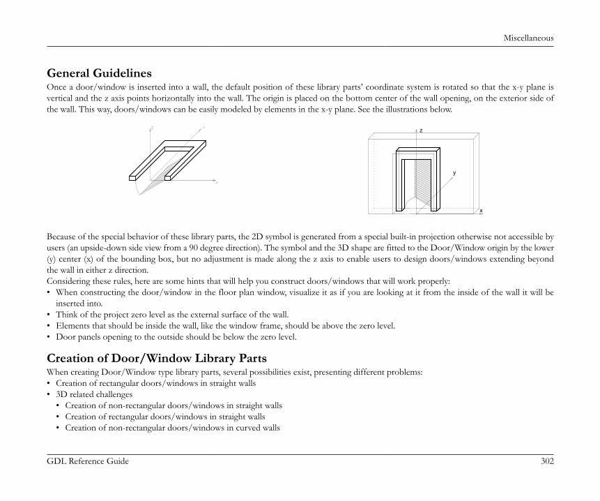
Miscellaneous
GDL Reference Guide 302
General GuidelinesOnce a door/window is inserted into a wall, the default position of these library parts’ coordinate system is rotated so that the x-y plane isvertical and the z axis points horizontally into the wall. The origin is placed on the bottom center of the wall opening, on the exterior side ofthe wall. This way, doors/windows can be easily modeled by elements in the x-y plane. See the illustrations below.
x
y
z
Because of the special behavior of these library parts, the 2D symbol is generated from a special built-in projection otherwise not accessible byusers (an upside-down side view from a 90 degree direction). The symbol and the 3D shape are fitted to the Door/Window origin by the lower(y) center (x) of the bounding box, but no adjustment is made along the z axis to enable users to design doors/windows extending beyondthe wall in either z direction.Considering these rules, here are some hints that will help you construct doors/windows that will work properly:• When constructing the door/window in the floor plan window, visualize it as if you are looking at it from the inside of the wall it will be
inserted into.• Think of the project zero level as the external surface of the wall.• Elements that should be inside the wall, like the window frame, should be above the zero level.• Door panels opening to the outside should be below the zero level.
Creation of Door/Window Library PartsWhen creating Door/Window type library parts, several possibilities exist, presenting different problems:• Creation of rectangular doors/windows in straight walls• 3D related challenges
• Creation of non-rectangular doors/windows in straight walls• Creation of rectangular doors/windows in straight walls• Creation of non-rectangular doors/windows in curved walls
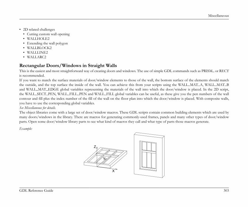
Miscellaneous
GDL Reference Guide 303
• 2D related challenges• Cutting custom wall opening• WALLHOLE2• Extending the wall polygon• WALLBLOCK2• WALLLINE2• WALLARC2
Rectangular Doors/Windows in Straight WallsThis is the easiest and most straightforward way of creating doors and windows. The use of simple GDL commands such as PRISM_ or RECTis recommended.If you want to match the surface materials of door/window elements to those of the wall, the bottom surface of the elements should matchthe outside, and the top surface the inside of the wall. You can achieve this from your scripts using the WALL_MAT_A, WALL_MAT_Band WALL_MAT_EDGE global variables representing the materials of the wall into which the door/window is placed. In the 2D script,the WALL_SECT_PEN, WALL_FILL_PEN and WALL_FILL global variables can be useful, as these give you the pen numbers of the wallcontour and fill plus the index number of the fill of the wall on the floor plan into which the door/window is placed. With composite walls,you have to use the corresponding global variables.See Miscellaneous for details.The object libraries come with a large set of door/window macros. These GDL scripts contain common building elements which are used bymany doors/windows in the library. There are macros for generating commonly-used frames, panels and many other types of door/windowparts. Open some door/window library parts to see what kind of macros they call and what type of parts those macros generate.
Example:
X
Y
Z
Miscellaneous
GDL Reference Guide 304
a=0.9: b=1.5: c=0.1: d=0.08e=0.08: f=0.9: g=0.03: h=3PRISM_ 10, c, -a/2, 0, 15, a/2, 0, 15, a/2, b, 15, -a/2, b, 15, -a/2, 0, -1, -a/2+d, d, 15, a/2-d, d, 15, a/2-d, b-d, 15, -a/2+d, b-d, 15, -a/2+d, d, -1ADD -a/2+d, f, 0BRICK a-2*d, e, cADD -g/2, -f+d, c/2GOSUB 1ADDZ -gGOSUB 1DEL 2MATERIAL "Glass"ADD 0, -f+d, c/2RECT a-2*d, f-dADDY f-d+eRECT a-2*d, b-f-e-dEND
1: FOR i=1 TO h-1 ADDX (a-2*d)/3 BLOCK g, f-d, g ADDY f+e-d BLOCK g, b-f-d-e, g DEL 1 NEXT i DEL h-1 RETURN
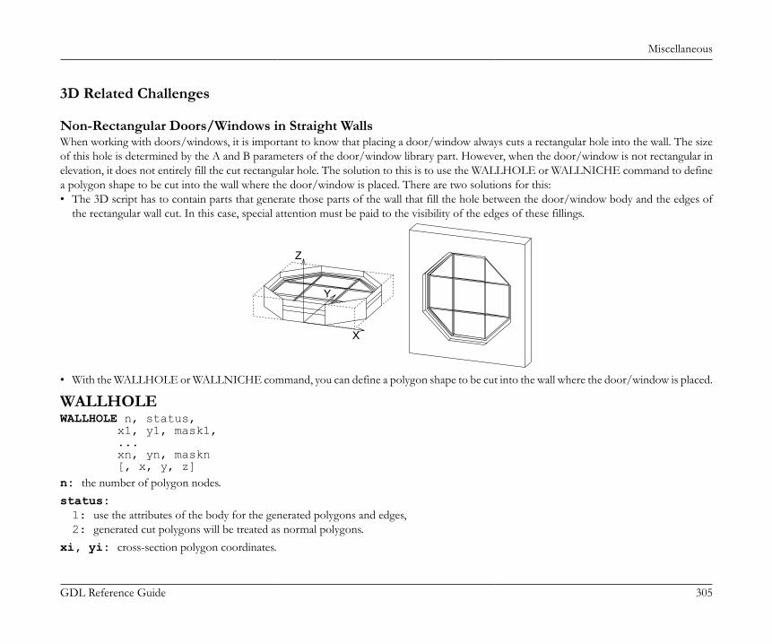
Miscellaneous
GDL Reference Guide 305
3D Related Challenges
Non-Rectangular Doors/Windows in Straight WallsWhen working with doors/windows, it is important to know that placing a door/window always cuts a rectangular hole into the wall. The sizeof this hole is determined by the A and B parameters of the door/window library part. However, when the door/window is not rectangular inelevation, it does not entirely fill the cut rectangular hole. The solution to this is to use the WALLHOLE or WALLNICHE command to definea polygon shape to be cut into the wall where the door/window is placed. There are two solutions for this:• The 3D script has to contain parts that generate those parts of the wall that fill the hole between the door/window body and the edges of
the rectangular wall cut. In this case, special attention must be paid to the visibility of the edges of these fillings.
X
Y
Z
• With the WALLHOLE or WALLNICHE command, you can define a polygon shape to be cut into the wall where the door/window is placed.
WALLHOLEWALLHOLE n, status, x1, y1, mask1, ... xn, yn, maskn [, x, y, z]n: the number of polygon nodes.status:1: use the attributes of the body for the generated polygons and edges,2: generated cut polygons will be treated as normal polygons.
xi, yi: cross-section polygon coordinates.
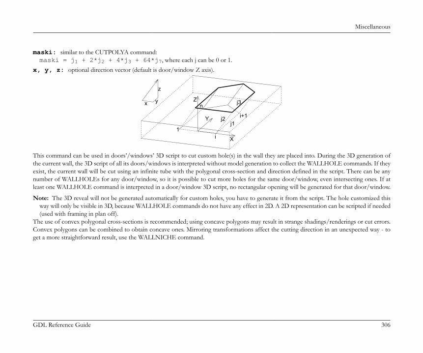
Miscellaneous
GDL Reference Guide 306
maski: similar to the CUTPOLYA command:maski = j1 + 2*j2 + 4*j3 + 64*j7, where each j can be 0 or 1.
x, y, z: optional direction vector (default is door/window Z axis).
x
z
y
1
n
i
i+1j1
j2
j3Z
Y
X
This command can be used in doors’/windows’ 3D script to cut custom hole(s) in the wall they are placed into. During the 3D generation ofthe current wall, the 3D script of all its doors/windows is interpreted without model generation to collect the WALLHOLE commands. If theyexist, the current wall will be cut using an infinite tube with the polygonal cross-section and direction defined in the script. There can be anynumber of WALLHOLEs for any door/window, so it is possible to cut more holes for the same door/window, even intersecting ones. If atleast one WALLHOLE command is interpreted in a door/window 3D script, no rectangular opening will be generated for that door/window.
Note: The 3D reveal will not be generated automatically for custom holes, you have to generate it from the script. The hole customized thisway will only be visible in 3D, because WALLHOLE commands do not have any effect in 2D. A 2D representation can be scripted if needed(used with framing in plan off).
The use of convex polygonal cross-sections is recommended; using concave polygons may result in strange shadings/renderings or cut errors.Convex polygons can be combined to obtain concave ones. Mirroring transformations affect the cutting direction in an unexpected way - toget a more straightforward result, use the WALLNICHE command.
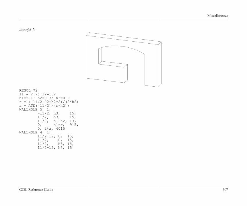
Miscellaneous
GDL Reference Guide 307
Example 1:
RESOL 72l1 = 2.7: l2=1.2h1=2.1: h2=0.3: h3=0.9r = ((l1/2)^2+h2^2)/(2*h2)a = ATN((l1/2)/(r-h2))WALLHOLE 5, 1, -l1/2, h3, 15, l1/2, h3, 15, l1/2, h1-h2, 13, 0, h1-r, 915, 0, 2*a, 4015WALLHOLE 4, 1, l1/2-l2, 0, 15, l1/2, 0, 15, l1/2, h3, 15, l1/2-l2, h3, 15
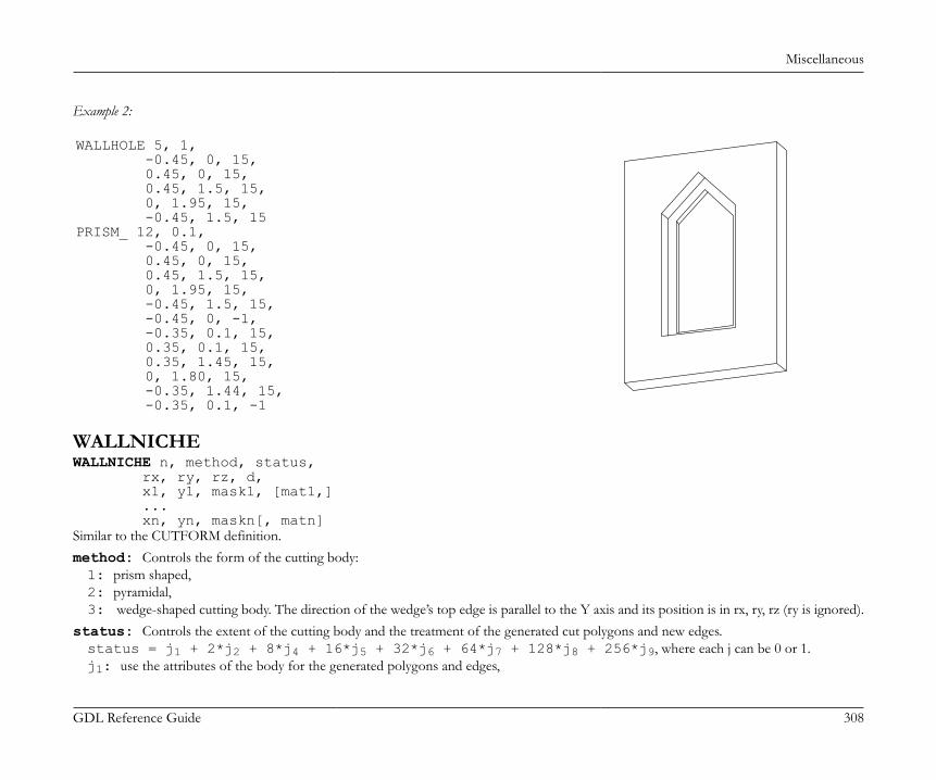
Miscellaneous
GDL Reference Guide 308
Example 2:
WALLHOLE 5, 1, -0.45, 0, 15, 0.45, 0, 15, 0.45, 1.5, 15, 0, 1.95, 15, -0.45, 1.5, 15PRISM_ 12, 0.1, -0.45, 0, 15, 0.45, 0, 15, 0.45, 1.5, 15, 0, 1.95, 15, -0.45, 1.5, 15, -0.45, 0, -1, -0.35, 0.1, 15, 0.35, 0.1, 15, 0.35, 1.45, 15, 0, 1.80, 15, -0.35, 1.44, 15, -0.35, 0.1, -1
WALLNICHEWALLNICHE n, method, status, rx, ry, rz, d, x1, y1, mask1, [mat1,] ... xn, yn, maskn[, matn]Similar to the CUTFORM definition.method: Controls the form of the cutting body:1: prism shaped,2: pyramidal,3: wedge-shaped cutting body. The direction of the wedge’s top edge is parallel to the Y axis and its position is in rx, ry, rz (ry is ignored).
status: Controls the extent of the cutting body and the treatment of the generated cut polygons and new edges.status = j1 + 2*j2 + 8*j4 + 16*j5 + 32*j6 + 64*j7 + 128*j8 + 256*j9, where each j can be 0 or 1.j1: use the attributes of the body for the generated polygons and edges,
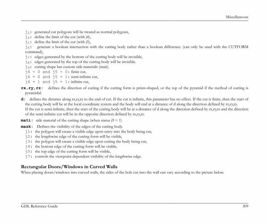
Miscellaneous
GDL Reference Guide 309
j2: generated cut polygons will be treated as normal polygons,j4: define the limit of the cut (with j4),j5: define the limit of the cut (with j5),j6: generate a boolean intersection with the cutting body rather than a boolean difference. (can only be used with the CUTFORMcommand),j7: edges generated by the bottom of the cutting body will be invisible,j8: edges generated by the top of the cutting body will be invisible.j9: cutting shape has custom side materials (mati).j4 = 0 and j5 = 0: finite cut,j4 = 0 and j5 = 1: semi-infinite cut,j4 = 1 and j5 = 1: infinite cut,
rx,ry,rz: defines the direction of cutting if the cutting form is prism-shaped, or the top of the pyramid if the method of cutting ispyramidal.
d: defines the distance along rx,ry,rz to the end of cut. If the cut is infinite, this parameter has no effect. If the cut is finite, then the start ofthe cutting body will be at the local coordinate system and the body will end at a distance of d along the direction defined by rx,ry,rz.If the cut is semi-infinite, then the start of the cutting body will be at a distance of d along the direction defined by rx,ry,rz and the directionof the semi-infinite cut will be in the opposite direction defined by rx,ry,rz.
mati: side material of the cutting shape (when status j9 = 1)mask: Defines the visibility of the edges of the cutting body.j1: the polygon will create a visible edge upon entry into the body being cut,j2: the lengthwise edge of the cutting form will be visible,j3: the polygon will create a visible edge upon exiting the body being cut,j4: the bottom edge of the cutting form will be visible,j5: the top edge of the cutting form will be visible,j7: controls the viewpoint dependent visibility of the lengthwise edge.
Rectangular Doors/Windows in Curved WallsWhen placing doors/windows into curved walls, the sides of the hole cut into the wall can vary according to the picture below.
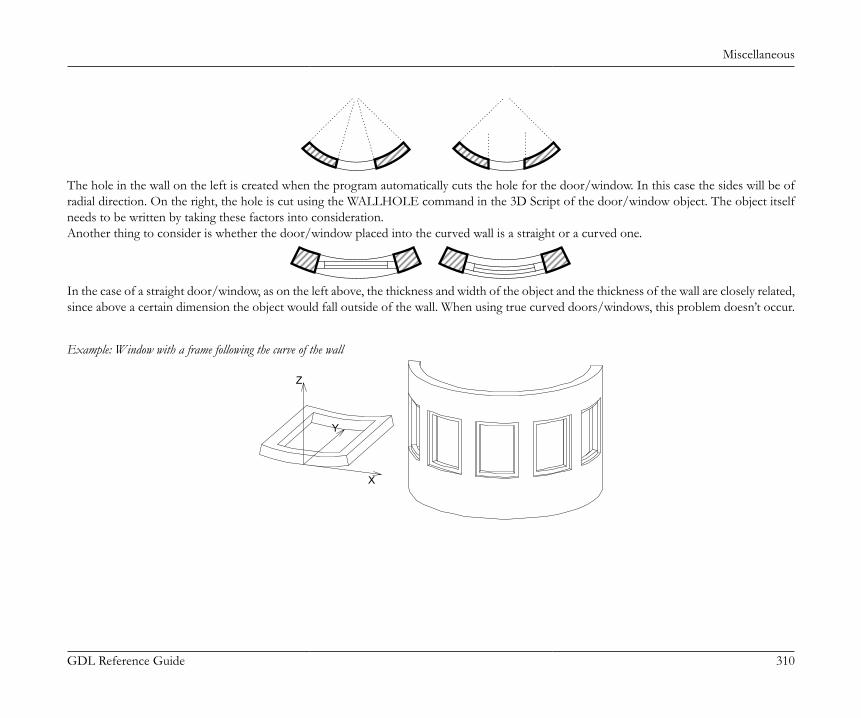
Miscellaneous
GDL Reference Guide 310
The hole in the wall on the left is created when the program automatically cuts the hole for the door/window. In this case the sides will be ofradial direction. On the right, the hole is cut using the WALLHOLE command in the 3D Script of the door/window object. The object itselfneeds to be written by taking these factors into consideration.Another thing to consider is whether the door/window placed into the curved wall is a straight or a curved one.
In the case of a straight door/window, as on the left above, the thickness and width of the object and the thickness of the wall are closely related,since above a certain dimension the object would fall outside of the wall. When using true curved doors/windows, this problem doesn’t occur.
Example: Window with a frame following the curve of the wall
Y
X
Z
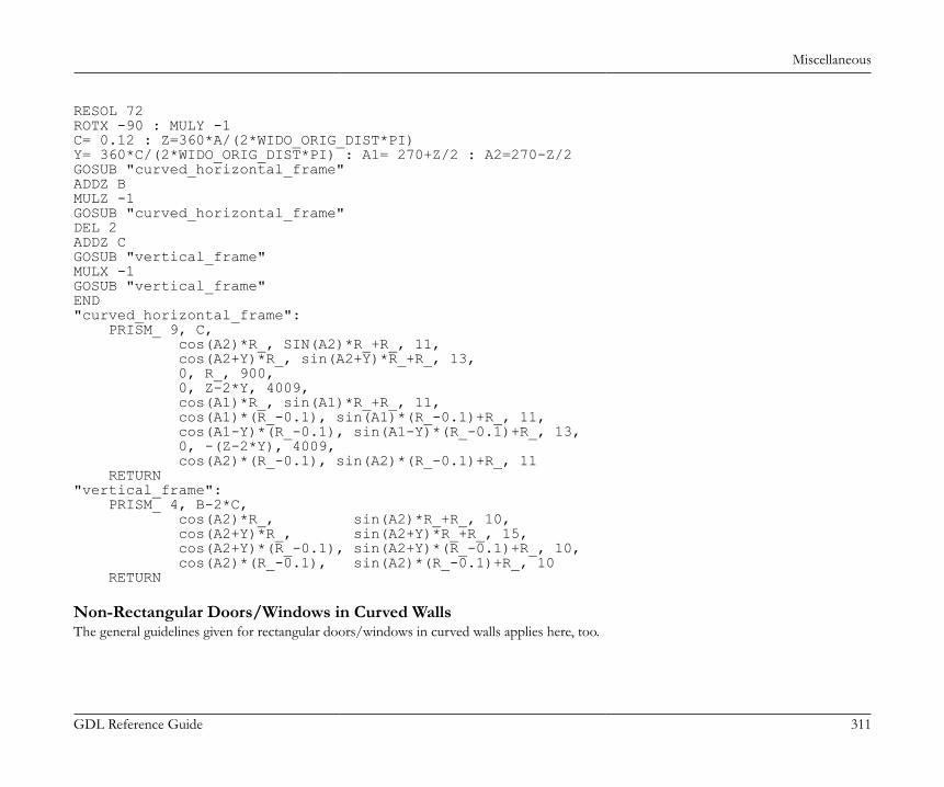
Miscellaneous
GDL Reference Guide 311
RESOL 72ROTX -90 : MULY -1C= 0.12 : Z=360*A/(2*WIDO_ORIG_DIST*PI)Y= 360*C/(2*WIDO_ORIG_DIST*PI) : A1= 270+Z/2 : A2=270-Z/2GOSUB "curved_horizontal_frame"ADDZ BMULZ -1GOSUB "curved_horizontal_frame"DEL 2ADDZ CGOSUB "vertical_frame"MULX -1GOSUB "vertical_frame"END"curved_horizontal_frame": PRISM_ 9, C, cos(A2)*R_, SIN(A2)*R_+R_, 11, cos(A2+Y)*R_, sin(A2+Y)*R_+R_, 13, 0, R_, 900, 0, Z-2*Y, 4009, cos(A1)*R_, sin(A1)*R_+R_, 11, cos(A1)*(R_-0.1), sin(A1)*(R_-0.1)+R_, 11, cos(A1-Y)*(R_-0.1), sin(A1-Y)*(R_-0.1)+R_, 13, 0, -(Z-2*Y), 4009, cos(A2)*(R_-0.1), sin(A2)*(R_-0.1)+R_, 11 RETURN"vertical_frame": PRISM_ 4, B-2*C, cos(A2)*R_, sin(A2)*R_+R_, 10, cos(A2+Y)*R_, sin(A2+Y)*R_+R_, 15, cos(A2+Y)*(R_-0.1), sin(A2+Y)*(R_-0.1)+R_, 10, cos(A2)*(R_-0.1), sin(A2)*(R_-0.1)+R_, 10 RETURN
Non-Rectangular Doors/Windows in Curved WallsThe general guidelines given for rectangular doors/windows in curved walls applies here, too.
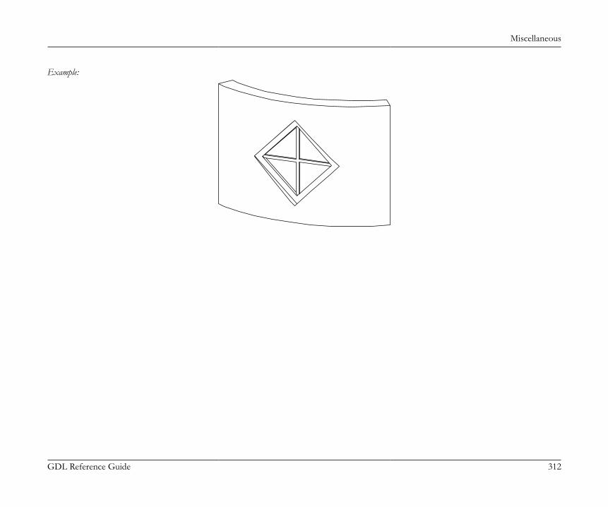
Miscellaneous
GDL Reference Guide 312
Example:
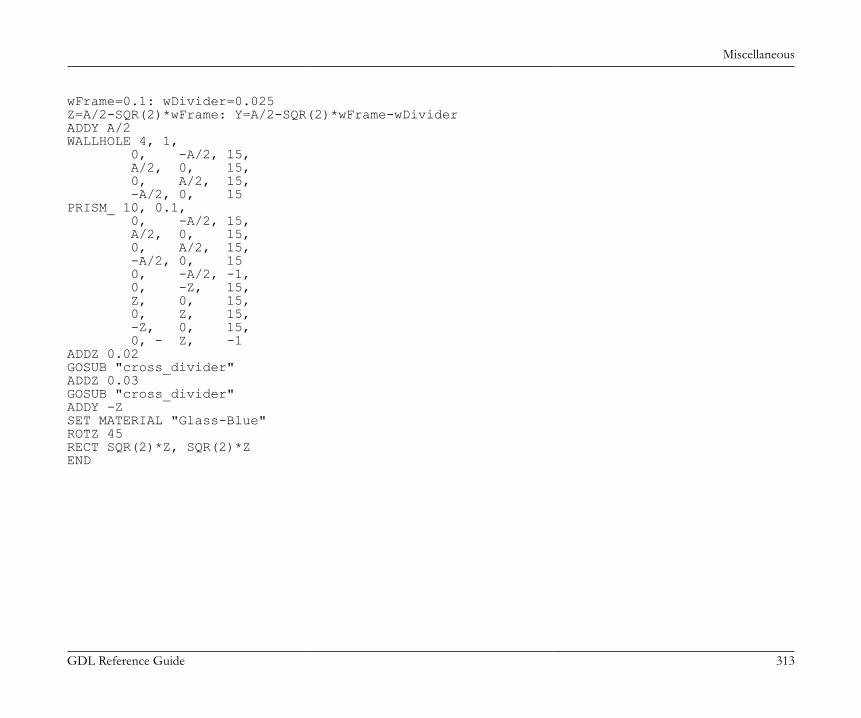
Miscellaneous
GDL Reference Guide 313
wFrame=0.1: wDivider=0.025Z=A/2-SQR(2)*wFrame: Y=A/2-SQR(2)*wFrame-wDividerADDY A/2WALLHOLE 4, 1, 0, -A/2, 15, A/2, 0, 15, 0, A/2, 15, -A/2, 0, 15PRISM_ 10, 0.1, 0, -A/2, 15, A/2, 0, 15, 0, A/2, 15, -A/2, 0, 15 0, -A/2, -1, 0, -Z, 15, Z, 0, 15, 0, Z, 15, -Z, 0, 15, 0, - Z, -1ADDZ 0.02GOSUB "cross_divider"ADDZ 0.03GOSUB "cross_divider"ADDY -ZSET MATERIAL "Glass-Blue"ROTZ 45RECT SQR(2)*Z, SQR(2)*ZEND
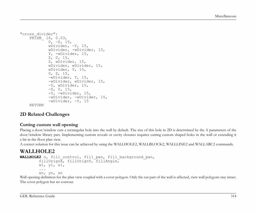
Miscellaneous
GDL Reference Guide 314
"cross_divider": PRISM_ 16, 0.03, 0, -Z, 15, wDivider, -Y, 15, wDivider, -wDivider, 15, Y, -wDivider, 15, Z, 0, 15, Z, wDivider, 15, wDivider, wDivider, 15, wDivider, Y, 15, 0, Z, 15, -wDivider, Y, 15, -wDivider, wDivider, 15, -Y, wDivider, 15, -Z, 0, 15, -Y, -wDivider, 15, -wDivider, -wDivider, 15, -wDivider, -Y, 15 RETURN
2D Related Challenges
Cutting custom wall openingPlacing a door/window cuts a rectangular hole into the wall by default. The size of this hole in 2D is determined by the A parameters of thedoor/window library part. Implementing custom reveals or cavity closures requires cutting custom shaped holes in the wall or extending ita bit in the floor plan view.A correct solution for this issue can be achieved by using the WALLHOLE2, WALLBLOCK2, WALLLINE2 and WALLARC2 commands.
WALLHOLE2WALLHOLE2 n, fill_control, fill_pen, fill_background_pen, fillOrigoX, fillOrigoY, fillAngle, x1, y1, s1, ... xn, yn, snWall opening definition for the plan view coupled with a cover polygon. Only the cut part of the wall is affected, view wall polygons stay intact.The cover polygon has no contour.
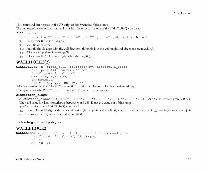
Miscellaneous
GDL Reference Guide 315
This command can be used in the 2D script of door/window objects only.The parameterization of the command is mainly the same as the one of the POLY2_B{2} command.fill_control:fill_control = 2*j2 + 8*j4 + 16*j5 + 32*j6 + 64*j7, where each j can be 0 or 1.j2: draw cover fill on the polygon,j4: local fill orientation,j5: local fill should align with the wall direction (fill origin is at the wall origin and directions are matching),j6: fill is cut fill (default is drafting fill),j7: fill is cover fill (only if j6 = 0, default is drafting fill).
WALLHOLE2{2}WALLHOLE2{2} n, frame_fill, fillcategory, distortion_flags, fill_pen, fill_background_pen, fillOrigoX, fillOrigoY, mxx, mxy, myx, myy, innerRadius, x1, y1, s1, ..., xn, yn, snAdvanced version of WALLHOLE2, where fill distortion can be controlled in an enhanced way.It is equivalent to the POLY2_B{5} command in the geometric definition.distortion_flags:distortion_flags = j1 + 2*j2 + 4*j3 + 8*j4 + 16*j5 + 32*j6 + 64*j7 + 128*j8, where each j can be 0 or 1.The valid value for distortion_flags is between 0 and 255. Don’t use value out of this range.j1-j7: similar to the POLY2_B{5} command,j8: local fill should align with the wall direction (fill origin is at the wall origin and directions are matching), meaningful only when j4 isset. Distortion matrix (mij parameters) are omitted.
Extending the wall polygon
WALLBLOCK2WALLBLOCK2 n, fill_control, fill_pen, fill_background_pen, fillOrigoX, fillOrigoY, fillAngle, x1, y1, s1, ... xn, yn, sn
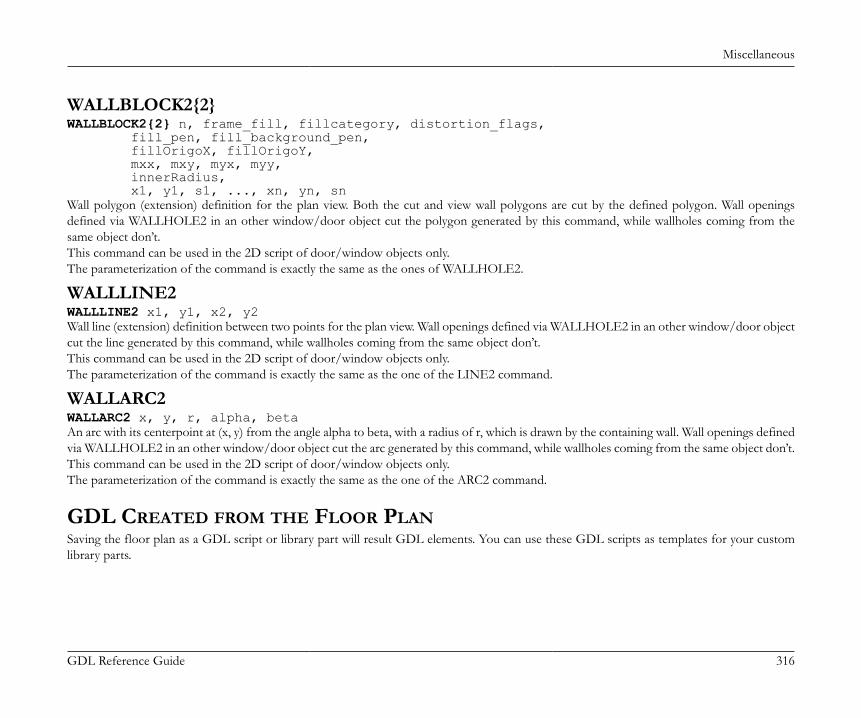
Miscellaneous
GDL Reference Guide 316
WALLBLOCK2{2}WALLBLOCK2{2} n, frame_fill, fillcategory, distortion_flags, fill_pen, fill_background_pen, fillOrigoX, fillOrigoY, mxx, mxy, myx, myy, innerRadius, x1, y1, s1, ..., xn, yn, snWall polygon (extension) definition for the plan view. Both the cut and view wall polygons are cut by the defined polygon. Wall openingsdefined via WALLHOLE2 in an other window/door object cut the polygon generated by this command, while wallholes coming from thesame object don’t.This command can be used in the 2D script of door/window objects only.The parameterization of the command is exactly the same as the ones of WALLHOLE2.
WALLLINE2WALLLINE2 x1, y1, x2, y2Wall line (extension) definition between two points for the plan view. Wall openings defined via WALLHOLE2 in an other window/door objectcut the line generated by this command, while wallholes coming from the same object don’t.This command can be used in the 2D script of door/window objects only.The parameterization of the command is exactly the same as the one of the LINE2 command.
WALLARC2WALLARC2 x, y, r, alpha, betaAn arc with its centerpoint at (x, y) from the angle alpha to beta, with a radius of r, which is drawn by the containing wall. Wall openings definedvia WALLHOLE2 in an other window/door object cut the arc generated by this command, while wallholes coming from the same object don’t.This command can be used in the 2D script of door/window objects only.The parameterization of the command is exactly the same as the one of the ARC2 command.
GDL CREATED FROM THE FLOOR PLANSaving the floor plan as a GDL script or library part will result GDL elements. You can use these GDL scripts as templates for your customlibrary parts.
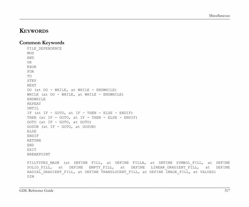
Miscellaneous
GDL Reference Guide 317
KEYWORDS
Common KeywordsFILE_DEPENDENCEMODANDOREXORFORTOSTEPNEXTDO (at DO - WHILE, at WHILE - ENDWHILE)WHILE (at DO - WHILE, at WHILE - ENDWHILE)ENDWHILEREPEATUNTILIF (at IF - GOTO, at IF - THEN - ELSE - ENDIF)THEN (at IF - GOTO, at IF - THEN - ELSE - ENDIF)GOTO (at IF - GOTO, at GOTO)GOSUB (at IF - GOTO, at GOSUB)ELSEENDIFRETURNENDEXITBREAKPOINT
FILLTYPES_MASK (at DEFINE FILL, at DEFINE FILLA, at DEFINE SYMBOL_FILL, at DEFINESOLID_FILL, at DEFINE EMPTY_FILL, at DEFINE LINEAR_GRADIENT_FILL, at DEFINERADIAL_GRADIENT_FILL, at DEFINE TRANSLUCENT_FILL, at DEFINE IMAGE_FILL, at VALUES)DIM
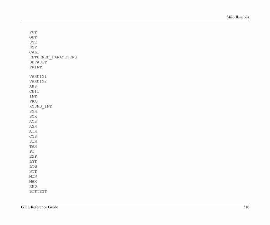
Miscellaneous
GDL Reference Guide 318
PUTGETUSENSPCALLRETURNED_PARAMETERSDEFAULTPRINT
VARDIM1VARDIM2ABSCEILINTFRAROUND_INTSGNSQRACSASNATNCOSSINTANPIEXPLGTLOGNOTMINMAXRNDBITTEST
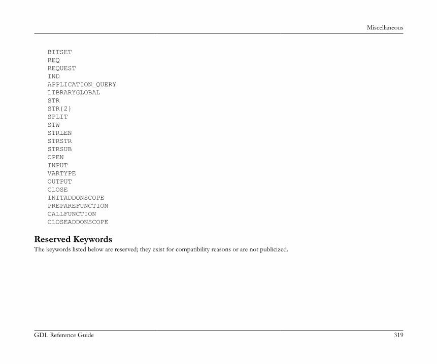
Miscellaneous
GDL Reference Guide 319
BITSETREQREQUESTINDAPPLICATION_QUERYLIBRARYGLOBALSTRSTR{2}SPLITSTWSTRLENSTRSTRSTRSUBOPENINPUTVARTYPEOUTPUTCLOSEINITADDONSCOPEPREPAREFUNCTIONCALLFUNCTIONCLOSEADDONSCOPE
Reserved KeywordsThe keywords listed below are reserved; they exist for compatibility reasons or are not publicized.
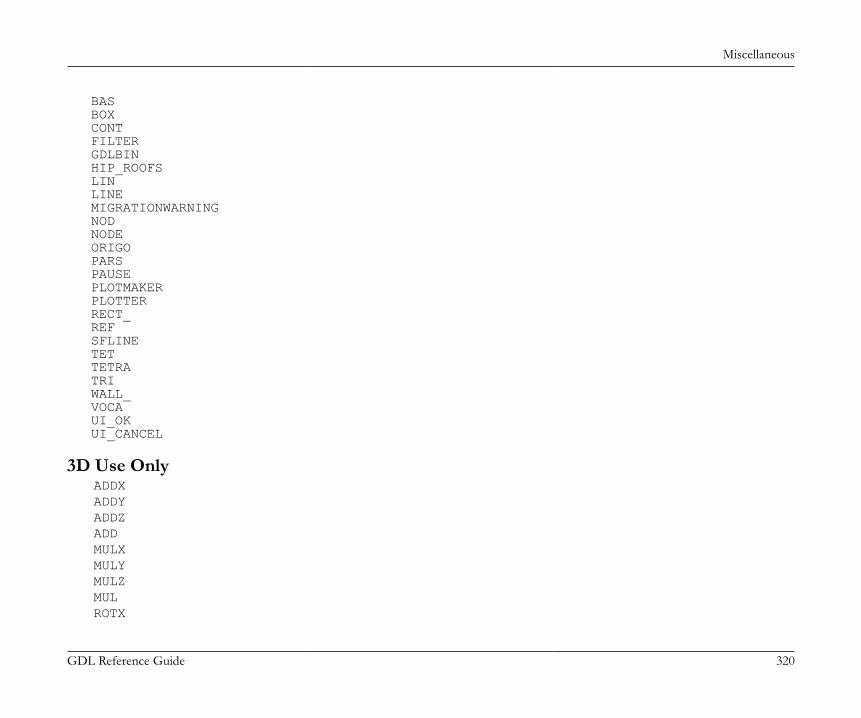
Miscellaneous
GDL Reference Guide 320
BAS BOX CONT FILTER GDLBIN HIP_ROOFS LIN LINE MIGRATIONWARNING NOD NODE ORIGO PARS PAUSE PLOTMAKER PLOTTER RECT_ REF SFLINE TET TETRA TRI WALL_ VOCA UI_OK UI_CANCEL
3D Use OnlyADDXADDYADDZADDMULXMULYMULZMULROTX
Miscellaneous
GDL Reference Guide 321
ROTYROTZROTXFORM
BLOCKBRICKCYLINDSPHEREELLIPSCONEPRISMPRISM_CPRISM_CPRISM_{2}BPRISM_FPRISM_HPRISM_SPRISM_SPRISM_{2}SLABSLAB_CSLAB_CWALL_BWALL_XWALL_XWALL_{2}BEAMCROOF_CROOF_{2}MESHARMCARME
Miscellaneous
GDL Reference Guide 322
ELBOWEXTRUDEPYRAMIDREVOLVEREVOLVE{2}RULEDRULED{2}SWEEPTUBETUBEACOONSMASSPOLYROOFEXTRUDEDSHELLREVOLVEDSHELLREVOLVEDSHELLANGULARRULEDSHELLTEXTBODYBASECUTPLANECUTEND (at CUTPLANE, at CUTPLANE{2}, at CUTPLANE{3}, at CUTPOLY, at CUTPOLYA, at CUTSHAPE)CUTPLANE{2}CUTPLANE{3}CUTPOLYCUTPOLYACUTSHAPECUTFORMGROUPENDGROUPADDGROUPADDGROUP{2}SUBGROUP
Miscellaneous
GDL Reference Guide 323
SUBGROUP{2}ISECTGROUPISECTGROUP{2}ISECTLINESPLACEGROUPKILLGROUPSWEEPGROUPSWEEPGROUP{2}SWEEPGROUP{3}CREATEGROUPWITHMATERIALBINARYWALLNICHE
HOTSPOTHOTLINEHOTARCLIN_RECTPOLYPOLY_PLANEPLANE_CIRCLEARCLIGHTPICTURERICHTEXTVERTTEVEVECTEDGEPGONPGON{2}
Miscellaneous
GDL Reference Guide 324
PIPGCOORMODELWIRESURFACESOLIDMATERIALSECT_FILLSECT_ATTRSSHADOWONOFFAUTODEFINE MATERIAL (at DEFINE MATERIAL, at DEFINE MATERIAL BASED_ON)BASED_ONDEFINE TEXTUREWALLHOLE
2D Use OnlyADD2MUL2ROT2
LINE2RECT2POLY2POLY2_POLY2_APOLY2_BPOLY2_B{2}POLY2_B{3}POLY2_B{4}POLY2_B{5}
Miscellaneous
GDL Reference Guide 325
ARC2CIRCLE2SPLINE2SPLINE2ATEXT2RICHTEXT2FRAGMENT2PROJECT2PROJECT2{2}PROJECT2{3}DRAWING2DRAWING3DRAWING3{2}DRAWING3{3}WALLHOLE2WALLHOLE2{2}WALLBLOCK2WALLBLOCK2{2}WALLLINE2WALLARC2
HOTSPOT2HOTLINE2HOTARC2PICTURE2PICTURE2{2}LINE_PROPERTYDRAWINDEXFILLLINE_TYPEDEFINE FILLDEFINE FILLADEFINE SYMBOL_FILL
Miscellaneous
GDL Reference Guide 326
DEFINE SOLID_FILLDEFINE EMPTY_FILLDEFINE LINEAR_GRADIENT_FILLDEFINE RADIAL_GRADIENT_FILLDEFINE TRANSLUCENT_FILLDEFINE IMAGE_FILLDEFINE LINE_TYPEDEFINE SYMBOL_LINE
2D and 3D UseDEL (at DEL, at DEL TOP)TOPNTRADDITIONAL_DATA (at LIGHT, at DEFINE MATERIAL BASED_ON)LETRADIUSRESOLTOLERPENSET (at [SET] STYLE, at [SET] MATERIAL, at [SET] FILL, at [SET] LINE_TYPE)STYLEDEFINE STYLEDEFINE STYLE{2}PARAGRAPHENDPARAGRAPHTEXTBLOCKTEXTBLOCK_
Non-Geometric Scripts
Properties ScriptDATABASE_SET
Miscellaneous
GDL Reference Guide 327
DESCRIPTORREF DESCRIPTORCOMPONENTREF COMPONENTBINARYPROPSURFACE3DVOLUME3DPOSITIONWALLSCOLUMNSBEAMSDOORSWINDOWSOBJECTSCEILSPITCHED_ROOFSLIGHTSHATCHESROOMSMESHESDRAWING
Parameter ScriptVALUESCUSTOM (at VALUES, at UI_INFIELD{3})RANGEPARAMETERS (at PARAMETERS, at CALL)LOCKALL (at LOCK, at HIDEPARAMETER, at CALL)HIDEPARAMETER
Interface ScriptUI_DIALOG
Miscellaneous
GDL Reference Guide 328
UI_PAGEUI_CURRENT_PAGEUI_BUTTON (at UI_BUTTON, at UI_TOOLTIP)UI_PREVUI_NEXTUI_FUNCTIONUI_LINKUI_PICT_BUTTON (at UI_PICT_BUTTON, at UI_TOOLTIP)UI_SEPARATORUI_GROUPBOXUI_PICT (at UI_PICT, at UI_TOOLTIP)UI_STYLEUI_OUTFIELD (at UI_OUTFIELD, at UI_TOOLTIP)UI_INFIELD (at UI_INFIELD, at UI_TOOLTIP)UI_INFIELD{2} (at UI_INFIELD{2}, at UI_TOOLTIP)UI_INFIELD{3} (at UI_INFIELD{3}, at UI_TOOLTIP)UI_RADIOBUTTON (at UI_RADIOBUTTON, at UI_TOOLTIP)UI_TOOLTIP
Forward and Backward Migration ScriptsSETMIGRATIONGUIDDELETED_PAR_VALUENEWPARAMETER
PARAMETER NAMING CONVENTIONBecause of the subtype hierarchy, the child library parts automatically inherit all parameters of the parent. (Read more about subtypes andparameter in the ArchiCAD User Guide). Parameters are identified by their name, so inherited and original parameters can have the same name.It is the responsibility of the library author to avoid conflicts by using descriptive parameter names prefixed with abbreviated library part names.For handler parameters and user-defined parameters, GRAPHISOFT has introduced a parameter naming convention in its libraries.
Miscellaneous
GDL Reference Guide 329
NoteHandlers add extra functionality to library parts (e.g. doors and windows cut holes in walls). Parameters names with the prefix ac_ arereserved for special parameters associated with ArchiCAD handlers (e.g. ac_corner_window). Check the standard ArchiCAD Librarysubtype templates for the complete list.
Standard GRAPHISOFT parameter names are marked with the gs_ prefix (e.g. gs_frame_pen). Please check the AC library parts for reference.Use these parameters in your GDL scripts to ensure full compatibility with GRAPHISOFT libraries.FM_ is reserved for ArchiFM (e.g. FM_Type) and HVAC_ is assigned to HVAC for ArchiCAD parameters (e.g. HVAC_Manufacturer).
GDL DATA I/O ADD-ONThe GDL Data In/Out Add-On allows you to access a simple kind of database by using GDL commands. Otherwise this Add-On is similarto the GDL Text In/Out Add-On.
Description of DatabaseThe database is a text file in which the records are stored in separate lines. The database can be queried and modified based on a single key.The key and the other items are separated by a character (specified in the OPEN command).The length of the lines does not need to be the same and even the number of columns in the records may be different.If a database is open for writing then there should be enough space beside the database file for duplicating the whole file.Opening and closing a database may be time consuming, so consecutive closing and opening of a database should be avoided.Large databases (with more than some hundred thousand records) should be ordered by the key values.A database can be opened, queried, modified and closed by this Add-On using the OPEN, INPUT, OUTPUT and CLOSE GDL commands.
Opening a Databasechannel = OPEN (filter, filename, paramstring)Opens the database. If the database file is to be opened for modification and the file does not exist, it creates a new file. If the database file isto be opened for reading and the file does not exist, an error message is displayed.Its return value is a positive integer that will identify the specific database. This value will be the database’s future reference number.If the database is opened before open command, it will generate a channel number only.filter: the internal name of the Add-On, in this case "DATA"filename: the name of the database file to be openedparamstring: add-on specific parameter, contains separator characters and file opening mode parameters
The paramstring may contain the following:
Miscellaneous
GDL Reference Guide 330
SEPARATOR: after the keyword between single quotation marks ('') you can define a character that you want to use in your text file (bothin case of writing and reading) for the separation of data fields. A special case is the tabulator character ('\t').MODE: after the keyword the mode of opening has to follow. There are three modes of opening:• RO (read only)• WA (read, append/modify)• WO (overwrite) Empties the database if exists.DIALOG: the 'filename' parameter is working as a file-identifier, otherwise it is a full-path-name. The file-identifier is a simple string, whichwill be matched to an existing file by the Add-On during a standard 'Open/Save as' dialog. This matching is stored by the Add-On and itwon't ask again except when the file is not available any more. If the open mode is read only, the Add-On will put up an Open dialog toselect an existing document. Otherwise the Add-On put up an alert-dialog to select between the 'Create' and 'Browse' options:• Create: create a new data-file (Save as Dialog).• Browse: search an existing data-file (Open dialog)LIBRARY: If the LIBRARY keyword is present in the parameter string, the data file has to be in the loaded library.Always put a comma (,) between the components of paramstring.If you use keywords that don’t exist, if the separator characters given are wrong or if there is nothing in the parameter string, the extensionwill use the default settings: "SEPARATOR = '\t', MODE = RO"
Example:ch1 = OPEN ("DATA", "file1", "SEPARATOR=';', MODE = RO, DIALOG")ch2 = OPEN ("DATA", "file2", "")ch3 = OPEN ("DATA", "newfile", "SEPARATOR = '\t', MODE = WA")
Reading Values from DatabaseINPUT (channel, recordID, fieldID, var1 [, var2, ...])Queries the database based on the key value.If it finds the record, it reads items from the record starting from the given column and puts the read values into the parameters in sequence.In the parameter list there has to be at least one value. The values can be of numeric or string type independently of the parameter type definedfor them. The return value is the number of successfully read values.If there are more parameters than values, the parameters without corresponding values will be set to zero. In case of empty columns (i.e. ifthere is nothing between the separator characters) the parameters will be set to zero.If it finds no record it returns (-1).channel: channel value, used to identify the connection.
Miscellaneous
GDL Reference Guide 331
recordID: key value (numeric or string).fieldID: the column number in the given record (the smallest number, 1 refers to the item after the key value).vari: variables to receive the read record items.
Example:! input of three values from the first column of the first rownr = INPUT (ch1, "key1", 1, v1, v2, v3)
PRINT nr, v1, v2, v3
Writing Values into DatabaseOUTPUT channel, recordID, fieldID, expr1 [, expr2, ...]In case of record creation or modification, it sets the record belonging to the given key value. The record will contain the given values in thesame sequence as they appear in the command. The values can be of numeric or string type. There has to be at least one expression.In case of deletion the record belonging to the given key value is removed from the database. The expression values are ignored, however atleast one should be specified.recordID: key value (numeric or string)fieldID: flag: specify 0 (or <= 0) to delete a record, specify 1 (or > 0) to create or modify a recordexpri: new item values of the found or new record in case of deletion these values are ignored
Example:string = "Date: 19.01.1996"a = 1.5OUTPUT ch2, "keyA", 1, "New record"OUTPUT ch2, "keyA", 1, "Modified record"OUTPUT ch2, "keyA", 0, 0 ! deletes the recordOUTPUT ch2, "keyB", 1, a, string
Closing DatabaseCLOSE channelchannel: channel valueCloses the database identified by the channel value.
Miscellaneous
GDL Reference Guide 332
GDL DATETIME ADD-ONThe DateTime extension allows you to set various formats for the current date and time set on your computer.The Add-On works the same way the GDL file operations. You have to open a channel, read the information and close the channel.This Add-On is also available by using the REQUEST GDL command, in which case the sequence of commands OPEN, INPUT and CLOSEis called internally. This is the simplest way to obtain the date/time information, with just a single GDL command line:REQUEST ("DateTime", format, datetimestring)The second parameter of the Request function is the same as that described in the OPEN function paramstring parameter.
Opening Channelchannel = OPEN (filter, filename, paramstring)Its return value is a positive integer that will identify the opened channel. This value will become the channel’s future reference number. Theparamstring can contain specifiers and other characters.filter: the internal name of the Add-On, in this case "DateTime"filename: unused (there is no need to open any file to get the system date and time)paramstring: add-on specific parameter, contains the desired output format of the date and timeThe specifiers are replaced with date and time values as follows:
%y year without century, as a decimal number (00-99)
%Y year with century, as a decimal number
%b abbreviated month name
%B full month name
%m month, as a decimal number (01-12)
%d day of the month as a decimal number (01-31)
%H hour (24-hour clock), as a decimal number (00-23)
%I hour (12-hour clock), as a decimal number (01-12)
%M minute, as a decimal number (00-59)
%S second, as a decimal number (00-59)
%P AM/PM designation for a 12-hour clock
Miscellaneous
GDL Reference Guide 333
%c date and time in the form: 01:35:56 PM Wednesday, March 27, 1996
%x date in the form Wednesday, March 27, 1996
%X time in the form 01:35:56 PM
%a abbreviated weekday name
%A full weekday name
%w weekday, as a decimal number (0 (Sunday)-6 (Saturday))
%j day of the year, as a decimal number (001-366)
%U week number of the year (with Sunday as the first day of the first week), as a decimal number
%W week number of the year (with Monday as the first day of the first week), as a decimal number (00-53)
%Z GDL ignores this specifier. According to the standard, it prints the time zone if it can be determined
%% the % character
Example:dstr = ""ch = OPEN ("DateTime", "", "%w/%m/%d/%Y, %H:%M%P")n = INPUT (ch, "", "", dstr)CLOSE (ch)PRINT dstr !it prints 3/03/27/1996, 14:36 PM
Reading Informationn = INPUT (channel, "", "", datetimestr)It reads a string type value which represents the date and/or time in the format given at the OPEN sequence. The second and third parametersare unused (they can be empty strings or 0-s as well)The return value is the number of successfully read values, in this case 1.channel: channel value, used to identify the connection.datetimestr: string type value
Closing ChannelCLOSE channelCloses the channel identified by the channel value.
Miscellaneous
GDL Reference Guide 334
GDL FILE MANAGER I/O ADD-ONThe GDL File Manager In-Out Add-On allows you to scan a folder for the contained files/subfolders from a GDL script.Specify the folder you would like to scan by using the OPEN command.Get the first/next file/folder name in the specified folder by using the INPUT command.Finish folder scanning by using the CLOSE command.
Specifying Folderchannel = OPEN (filter, filename, paramstring)channel: folder idfilter: the internal name of the Add-On, in this case "FileMan"filename: the name of folder to be scanned (OS dependent path) - folder id string (in DIALOG mode - see later)paramstring: Add-on specific parameter. The parameters in paramString must be separated by commas (,).1. parameter: FILES/FOLDERS: What would you like to search for?2. parameter (optional): DIALOG: Indicates that the folder is given by a file id string instead of a file path. When this isthe case, at the first time (and each time when the corresponding file path seems to be invalid) the user will be faced a dialog box to set theid string - file path correspondence, which will be stored.
Example: Opening the root directory of the C drive (on a PC) for file-scanningfolder = OPEN ("FileMan", "c:\", "FOLDERS")
Getting File/Folder Namen = INPUT (channel, recordID, fieldID, var1 [, var2, ...])channel: folder id (returned by the OPEN command)recordID: 0 (reserved for further development)fieldID: 0 (reserved for future development)var1, ...: variable(s) to receive the file/folder name(s)n: the number of successfully filled variables
Example: Fetching the next file name from the specified foldern = INPUT (folder, 0, 0, fileName)
Miscellaneous
GDL Reference Guide 335
If it succeeds, n will be 1. If there are no more files/subfolders the variable n will be set to zero.
Finishing Folder ScanningCLOSE (channel)Closes the folder identified by the channel value.
Example: Listing a single foldertopFolder = open ("FileMan", "MyFavouriteFolder", "files, dialog")y = 0n = input (topFolder, 0, 0, fileName)while n = 1 do text2 0, y, fileName y = y - 0.6 n = input (topFolder, 0, 0, fileName)endwhileclose (topFolder)This code segment (as the 2D script section of an object, for example) lists the files in the folder specified by the MyFavouriteFolder identifier.At first usage, the user will have to assign an existing folder to this identifier. Later, MyFavouriteFolder id will represent that folder.
GDL TEXT I/O ADD-ONThe GDL Text In/Out Add-On allows you to open external text files for reading/writing and to manipulate them by putting/getting valuesfrom/to GDL scripts.This Add-On interprets the strings on the parameter list of the OPEN, INPUT, OUTPUT commands from the GDL script.The created files are placed in a subfolder of the application data folder if it is given by a relative path. The folder can contain subfolders wherethe extension will look for existing files. It can read and write TEXT type files.
Opening Filechannel = OPEN (filter, filename, paramstring)Opens the file. If the file into which you want to write doesn’t exist, it creates the file. If a file to be read doesn’t exist, an error message is displayed.Its return value is a positive integer that will identify the specific file. This value will be the file’s future reference number.filter: the internal name of the Add-On, in this case "TEXT"filename: the name of the file to be openedparamstring: add-on specific parameter, contains separator characters and file opening mode parameters
Miscellaneous
GDL Reference Guide 336
The paramstring may contain the following:SEPARATOR: after the keyword between apostrophes (') you can assign a character to use in the text file (for both writing and reading)to separate columns. Special cases are the tabulator ('\t') and the new row ('\n') characters.MODE: the mode of opening has to follow this keyword. There are only three modes of opening:• RO (read only)• WA (write only, append at the end of the file)• WO (write only, overwrite) the data previously stored in the file will be lost!A file cannot be open for reading and writing at the same time.DIALOG: If this keyword is present, a dialog box will appear in which you can enter a file name.FULLPATH: If this keyword is present, the file name will be interpreted as a full path name.LIBRARY: If this keyword is present, the data file must be in the loaded library.Always put a comma (,) between the keywords.If you use keywords that don’t exist, if the separator characters given are wrong or if there is nothing in the parameter string, the extensionwill use the default settings: "SEPARATOR = '\t', MODE = RO"
Example:ch1 = OPEN ("TEXT", "file1", "SEPARATOR = ';', MODE = RO")ch2 = OPEN ("TEXT", "file2", "")ch3 = OPEN ("TEXT", "file3", "SEPARATOR = '\n', MODE = WO")
Reading ValuesINPUT (channel, recordID, fieldID, var1 [, var2, ...])It reads as many values from the given starting position of the file identified by the channel value as many parameters are given. In the parameterlist there has to be at least one value. The function puts the read values into the parameters in sequence. The values can be of numeric or stringtype independently of the parameter type defined for them.The return value is the number of successfully read values, in case of end of file (-1).Both the row and the column numbers have to be positive integers, otherwise you will get an error message.If the row or column numbers are incorrect, the input will not be carried out. (n = 0)If the row and the column can be identified, as many values shall be input from the given starting position as many parameters are given, or ifthere are more parameters than values, the parameters without corresponding values will be set to zero.In case of empty columns (i.e. if there is nothing between the separator characters) the parameters will be set to zero.channel: channel value, used to identify the connection.recordID: the row number (numeric or string)
Miscellaneous
GDL Reference Guide 337
fieldID: the column number in the given rowvar1, ...: variables to receive the read record items
Example:nr = INPUT (ch1, 1, 1, v1, v2, v3) ! input of three values! from the firstcolumn of the first rowPRINT nr, v1, v2, v3
Writing ValuesOUTPUT channel, recordID, fieldID, expr1 [, expr2, ...]Outputs as many values into the file identified by the channel value from the given position as many expressions are defined. There has to beat least one expression. The types of the output values are the same as those of the expressions.In case of a text extension, the OUTPUT will either (depending on the mode of opening) overwrite the file or add to the end of the file thegiven expressions to consecutive positions using between them the separator characters defined when opening the file. In this case, the givenposition is not interpreted.channel: channel valuerecordID: The recordID is used to direct the new rows in the output
If the recordID is positive, the output values will be followed by a new row, otherwise the last value will be followed by a separator character.fieldID: no role, its value is not usedexpr1: values to output
Example:string = "Date: 19.01.1996"a = 1.5OUTPUT ch2, 1, 0, string ! string followed by a new rowOUTPUT ch2, 0, 0, a, a + 1, a + 2! separator character after a + 2 ! without new row
Closing FileCLOSE channelCloses the text file identified by the channel value.channel: channel value
Miscellaneous
GDL Reference Guide 338
Example:A GDL object that will simply copy the contents of the "f1" file both into the "f2" and the "f3" files, but will write all the values tabulatedin "f1" into a separate row in both "f2" and "f3".ch1 = open ("TEXT", "f1", "mode = ro")ch2 = open ("TEXT", "f2", "separator = '\n', mode = wo")ch3 = open ("TEXT", "f3", "separator = '\n', mode = wo")i = 1
1: n = input (ch1, i, 1, var1, var2, var3, var4) if n <> -1 then output ch2, 1, 0, var1, var2, var3, var4 output ch3, 1, 0, var1, var2, var3, var4 i = i + 1 goto 1 else goto "close all" endif
"close all": close ch1 close ch2 close ch3 end
PROPERTY GDL ADD-ONThe purpose of this add-on is to make an ArchiCAD property database accessible from GDL scripts. You can open database tables and querytheir contents, just like you would do it with SQL. You can query single records and multiple records (lists). Note that you cannot modify thedatabase, and you cannot append records to it.For the detailed description of the property database please refer to the “ArchiCAD Calculation Guide” in the Help menu.
Open property databaseOPEN ("PROP", "database set name", "[database files]")Return value: channel numberOpens a communication channel to the given database files. The content of the database files are read into memory for faster access. As longas it is open modifications to the property database will not be accessible from this add-on. This is usually not a problem though.
Miscellaneous
GDL Reference Guide 339
database set name: an arbitrary name that will identify a set of database files in subsequent OPEN calls.database files: a list of text files that are part of the property database. This parameter is optional, if you have previously assigneddatabase set name to the files you would like to read. The order of the files is fixed: key file, component file, descriptorfile, unit file. You don’t need to give full paths, because ArchiCAD will look up these files for you in the active libraries. If you uselong filenames or names with spaces, put them between quotes (' or ").
Example 1:channel = OPEN ("PROP", "sample", "'AC 8_KEY.txt', 'AC 8_COMP.txt', 'AC 8_DESC.txt', 'AC 8_UNIT.txt'")Opens a database that consists of the files above (those are the files of the ArchiCAD Property database), and names it "sample". Note thatinside the third parameter you must use a different quotation character (you can use " and ').
Example 2:channel = OPEN ("PROP", "sample", "")This command can be issued after explicitly opening the database files (like in example 1), but before closing it. This lets you use the explicitcommand at one place in the Master_GDL script, and use the shorter version later.
Close property databaseCLOSE (channel_number)Return value: noneCloses the previously opened communication channel.
Input to property databaseINPUT (channel_number, "query type", "field list", variable1 [, ...])channel_number: a valid communication channel number given by a previous OPEN command.query type: specifies the query you would like to execute. The add-on understands the following keywords:
• Single-record queries:• KEY, <keycode> - query the record from the key database where <keycode> is the value of the keycode attribute. Valid fields:
KEYCODE, KEYNAME• UNIT, <unitcode> - query the record from the unit database where <unitcode> is the value of the unit code attribute. Valid fields:
UNITCODE, UNITNAME, UNITFORMATSTR
Miscellaneous
GDL Reference Guide 340
• COMP, <keycode>, <code> - query the record from the unit database where <keycode> is the key code attribute value, and <code>is the component code attribute value. Valid fields: KEYCODE, KEYNAME, CODE, NAME, QUANTITY, QUANTITYSTR,UNITCODE, UNITNAME, UNITFORMATSTR
• DESC, <keycode>, <code> - query the record from the unit database where <keycode> is the key code attribute value, and <code>is the descriptor code attribute value. Valid fields: KEYCODE, KEYNAME, CODE, NAME, NUMOFLINES, FULLNAME
• Listing queries:• KEYLIST - list all records in the key database. Valid fields: KEYCODE, KEYNAME• UNITLIST - list all records in the unit database. Valid fields: UNITCODE, UNITNAME, UNITFORMATSTR• COMPLIST[, <keycode>] - list all records in the component database, or if <keycode> is given, then only those records are listed whose
keycode equals <keycode>. Valid fields: KEYCODE, KEYNAME, CODE, NAME, QUANTITY, QUANTITYSTR, UNITCODE,UNITNAME, UNITFORMATSTR
• DESCLIST[, keycode] - list all records in the descriptor database, or if <keycode> is given, then only those records are listed whosekeycode equals <keycode>. Valid fields: KEYCODE, KEYNAME, CODE, NAME, NUMOFLINES, FULLNAME
• COMPDESCLIST[, <keycode>] - list all records in the component and the descriptor database, or if <keycode> is given, then only thoserecords are listed whose keycode equals <keycode>. Valid fields: ISCOMP, KEYCODE, KEYNAME, CODE, NAME, QUANTITY,QUANTITYSTR, UNITCODE, UNITNAME, UNITFORMATSTR, NUMOFLINES, FULLNAMEUse this query with care! If either field is not valid in a database (eg. FULLNAME in the component database) it will be simply leftout from the resulting list (you should be aware of that)
field list: lists the database attributes whose values you would like to see in the output. If the output is a list, it will be sorted in theorder of the fields listed here.The following fields can be used:• KEYCODE - key code attribute. Type: string. Usable in queries: KEY, COMP, DESC, KEYLIST, COMPLIST, DESCLIST,
COMPDESCLIST• KEYNAME - key name attribute. Type: string. Usable in queries: KEY, COMP, DESC, KEYLIST, COMPLIST, DESCLIST,
COMPDESCLIST.• UNITCODE - unit code attribute. Type: string. Usable in queries: UNIT, COMP, UNITLIST, COMPLIST, COMPDESCLIST• UNITNAME - unit name attribute. Type: string. Usable in queries: UNIT, COMP, UNITLIST, COMPLIST, COMPDESCLIST• UNITFORMATSTR - GDL format string of the unit. Type: string. Usable in queries: UNIT, COMP, UNITLIST, COMPLIST,
COMPDESCLIST.• CODE - component or descriptor code attribute (depends on the query). Type: string. Usable in queries: COMP, DESC, COMPLIST,
DESCLIST, COMPDESCLIST.
Miscellaneous
GDL Reference Guide 341
• NAME - name of component or the first line of a descriptor record. Type: string. Usable in queries: COMP, DESC, COMPLIST,DESCLIST, COMPDESCLIST.
• QUANTITY - quantity of a component as a number (for calculations). Type: number. Usable in queries: COMP, COMPLIST,COMPDESCLIST.
• QUANTITYSTR - quantity of a component in string format. Type: string. Usable in queries: COMP, COMPLIST, COMPDESCLIST.• NUMOFLINES - number of lines in a descriptor record. Type: number. Usable in queries: DESC, DESCLIST.• FULLNAME - the whole descriptor record. Type: string(s). Usable in queries: DESC, DESCLIST.• ISCOMP - tells you whether the next record is a component or a descriptor. Type: number (1 if component, 0 if descriptor). Usable in
queries: COMPDESCLISTvariables: will hold the result of the query upon completion. You can list several variables if you know exactly how many you need (eg.
with single queries) or you can specify a dynamic array. The records are listed sequentially.
Example 1:INPUT (channel, "KEY, 001", "KEYNAME", keyname)This is a simple query: the name of the key with "001" code is put into the keyname variable.
Example 2:INPUT (channel, "DESC, 004, 10", "NUMOFLINES, FULLNAME", desc_txt)The descriptor record with keycode "004" and code "10" is processed, the number of lines of the description text and the text itself is putinto the desc_txt array. The result is:desc_txt[1] = <numoflines> (number)desc_txt[2] = <first row of description> (string)...desc_txt[<numoflines+1>] = <last row of description>
Example 3:INPUT (channel, "COMPLIST", "NAME, KEYNAME, QUANTITY", comp_list)Create a component list, sort it by the name field, then by the keyname and finally by the quantity field and put it into the comp_list array.The result is:complist[1] = <name1> (string)complist[2] = <keyname1> (string)complist[3] = <quantity1> (number)complist[4] = <name2> (string)
Miscellaneous
GDL Reference Guide 342
... etc.
Example 4:INPUT (channel, "COMPDESCLIST, 005", "ISCOMP, KEYNAME, NAME, QUANTITY", x_list)Creates a common component and descriptor list, which means that records from both tables are listed where <keycode> is "005". The output is:x_list[1] = 0 (number, 0 –> it is a descriptor)x_list[2] = <name1> (string –> descriptors do not have <keyname> field, so it is left out)x_list[3] = 0 (number, descriptors do not have quantity field)...x_list[(n*2)-1] = 1 (number –> there were n-1 descriptors listed, now the components come)x_list[n*2] = <keyname_n> (string) ... etc.
Output to property databaseThis command is not implemented in this add-on, since property databases are read-only.
GDL XML EXTENSIONThis extension allows reading, writing and editing XML files. It implements a subset of the Document Object Model (DOM) interface. XMLis a text file that uses tags to structure data into a hierarchical system, similar to HTML. An XML document can be modeled by a hierarchicaltree structure whose nodes contain the data of the document. The following node types are known by the extension:• Element: what is between a start-tag and an end-tag in the document, or for an empty-element it can be an empty-element tag. Elements have
a name, may have attributes, and usually but not necessarily have content. It means that element type nodes can have child nodes. Attributesare held in an attribute list where each attribute has a different name and a text value.
• Text: a character sequence. It cannot have child nodes.• Comment: text between the comment delimiters: <!-- the comment itself --> . In the text of the comment each '-' character must be followed
by a character different from '-'. It also means that the following is illegal: <!-- comment ---> . Comment type nodes cannot have child nodes.• CDATASection: text between the CDATA section delimiters: <![CDATA[ the text itself ]]> . In a CDATA section characters that have special
meaning in an XML document need not (and must not) be escaped. The only markup recognized is the closing "]]>". CData section nodescannot have child nodes.
• Entity-reference: reference to a predefined entity. Such a node can have a read-only subtree and this subtree gives the value of the referencedentity. During the parsing of the document it can be chosen that entity references are translated into text nodes.
On the top level it is obligatory to have exactly one element type node (the root), and there can be several comment type nodes, as well. Thedocument type node of the DOM interface is not available through the extension’s interface.
Miscellaneous
GDL Reference Guide 343
name value
Element name of the tag "" (empty string)
Text "#text" the text content of the node
Comment "#comment" the text content of the node
CDATASection "#cdata-section" the text content of the node
Entity-reference name of the referenced entity "" (empty string)
For each node in the tree there is a name and a value string associated whose meanings depend on the type of the node:
Element: ELEM
Text: TXT
Comment: CMT
CDATA section: CDATA
Entity reference: EREF
The success or error code of an OPEN, INPUT or OUTPUT command can be retrieved by the GetLastError instruction of the INPUTcommand.
Opening an XML Documentchannel = OPEN (filter, filename, parameter_string)filter: file extension. This should be 'XML'.filename: name and path of the file to open (or create), or an identifier name if the file is opened through a dialog box and the file’s
location is given by the user.parameter_string: a sequence of character flags that determine the open-mode:'r': open in read-only mode. In general only the INPUT command can be used.'e': entity references are not translated into text nodes in the tree. Without this flag there are no entity-references in the document structure.'v': validity check is performed during reading in and writing out. If a DTD exists in the document, the document’s structure must agreewith it. Without this flag a well-structured but invalid document can be read in and written out without error message.'n': create a new file. If the file exists, the open will fail. (After the OPEN the CreateDocument instruction must be the first to execute.)
Miscellaneous
GDL Reference Guide 344
'w': overwrite file with empty document if it exists. If it doesn’t exist, a new file will be created. (After the OPEN the CreateDocumentinstruction must be the first to execute.)'d': the file is obtained from the user in a dialog box. In later runs it will be associated with the identifier given in the filename parameterof the OPEN command. (If the identifier is already associated to a file, the dialog box will not be opened to the user.)'f': the filename parameter contains a full path.'l': the file is in the loaded library parts.
channel: used to identify the connection in subsequent I/O commands.If you want to open an existing XML file for modification, then none of the 'r', 'n' and 'w' flags must be set in the parameter string. Only one ofthe 'd', 'f' and 'l' flags should be set. If none of these flags is set then filename is considered to be a path relative to the user’s documents folder.
Reading an XML DocumentDOM is an object-oriented model that cannot be adapted to a BASIC-like language like GDL directly. To represent the nodes in the hierarchytree we define position descriptors. When we want to walk through the nodes of the tree, first we have to request a new position descriptorfrom the extension. Originally a new descriptor points to the root element. The descriptor is in fact a 32 bit identification number whose valuehas no interest for the GDL script. The position it refers to can be changed as we move from one node in the tree to another.INPUT (ch, recordID, fieldID, var1, var2, ...)ch: channel returned by the OPEN command.recordID: instruction name plus parameters.fieldID: usually a position descriptor.var1, var2, ...: optional list of variables receiving returned data.INPUT instructions:• GetLastError: retrieve the result of the last operation
recordID: "GetLastError"fieldID: ignoredreturn values:var1: error code / okvar2: the explanation text of error / ok
• NewPositionDesc: request for a new position descriptorrecordID: "NewPositionDesc"fieldID: ignoredreturn value: var1: the new position descriptor (initially refers to the root)
Miscellaneous
GDL Reference Guide 345
• CopyPositionDesc: request for a new position descriptor whose starting node is taken from another descriptor.recordID: "CopyPositionDesc"fieldID: an existing position descriptorreturn value: var1: the new position descriptor (initially refers to where the descriptor given in fieldID refers to)
• ReturnPositionDesc: when a position descriptor is no longer needed.recordID: "ReturnPositionDesc"fieldID: the position descriptorvar1: ignoredCall this instruction when a position descriptor received from the NewPositionDesc or CopyPositionDesc instructions is no longer used.
• MoveToNode: change the position of a descriptor. (and retrieve the data of the new node)This instruction can be used for navigating in the tree hierarchy.recordID: "MoveToNode searchmode nodename nodetype nodenumber">fieldID: position descriptorsearchmode (or movemode): the nodename parameter must contain a path that determines an element or entity reference node in the xmldocument.The path is relative to the node given in fieldID. The delimiter is the ':' character (which is otherwise an accepted character in an element'sname so this doesn't work for all cases). The '..' string in the path means a step to the parent node. The starting node can be different froman element or entity reference node, in which case the path must begin with '..' to step back. If there are several element nodes on the samelevel with the same name then the first one is chosen.For the following move-modes the rest of the parameters must not be present:ToParent: moves to the parent of the node given in fieldID.ToNextSibling: moves to the next node on the same level.ToPrevSibling: moves to the previous node on the same level.ToFirstChild: moves to the first descendant of the fieldID node.ToLastChild: moves to the last descendant of the fieldID node.The following are the search-modes for which the rest of the parameters may occur, but they have default values if not present:FromNextSibling: searching starts from the next node on the same level and it moves forward.FromPrevSibling: searching starts from the node before fieldID and it moves backward on the same level.FromFirstChild: searching starts from the first descendant of the fieldID node and moves forward.FromLastChild: searching starts from the last descendant of the fieldID node and moves backward.nodename: the searching considers those nodes only whose name or value matches nodename. The * and ? characters in nodename areconsidered as wildcard characters. For element and entity reference type nodes the name is compared, while for text, comment and CDATAsection nodes the value is compared. Default value: *

Miscellaneous
GDL Reference Guide 346
nodetype: the searching considers those nodes only whose type is allowed by nodetype. The * means all types are allowed. Otherwise thetype keywords can be combined with the + character to form the nodetype (it must be one word without spaces, like TXT+CDATA.) Thedefault value is *nodenumber: if there are several matching nodes, this gives the number of the searched node in the sequence of matching nodes. (Startsfrom 1) Default value: 1return values:var1: name of the nodevar2: value of the nodevar3: type keyword of the node
Example:We want to move backwards on the same level to the 2nd node that is an element or an entity reference and whose name starts with K:INPUT (ch, "MoveToNode FromPrevSibling K* ELEM+EREF 2", posDesc, name, val, type)
• GetNodeData: retrieve the data of a given node.recordID: "GetNodeData"fieldID: the position descriptorreturn values:var1: name of the nodevar2: value of the nodevar3: type keyword of the node
• NumberofChildNodes: gives the number of child nodes of a given noderecordID: "NumberofChildNodes nodetype nodename"The following optional parameters can narrow the set of child nodes considered:nodetype: allowed node types as defined in the MoveToNode instructionnodename: allowed node names or values as defined in the MoveToNode instructionfieldID: position descriptorreturn values:var1: number of child nodes
• NumberofAttributes: returns the number of attributes of an element node.recordID: "NumberofAttributes attrname"attrname: if present, it can narrow the set of attributes considered as only those attributes will be counted whose names (and not the values)match attrname. In attrname the * and ? characters are considered wildcard characters.fieldID: position descriptor (must refer to an element node)
Miscellaneous
GDL Reference Guide 347
return values:var1: number of attributes
• GetAttribute: return the data of an attribute of an element noderecordID: "GetAttribute attrname attrnumber"fieldID: position descriptor (must refer to an element node)optional parameters:attrname: give the name of the attribute. The * and ? are considered wildcard characters. Default value: *attrnumber: If several attribute matches attrname, attrnumber chooses the attribute in the sequence of matching attributes. (Counting startsfrom 1.) Default value: 1return values:var1: value of the attributevar2: name of the attribute
• Validate: check the validity of the document.The validity is not checked during a document modification instruction. It is checked during writing back the file to disk if the 'v' flag was setin the open-mode string. A validity check can be forced any time by the Validate instruction, however it can consume considerable amountof time and memory so it is not advisable to do so after every modification.recordID: "Validate"fieldID: ignoredvar1: ignored
Modifying an XML DocumentOUTPUT (ch, recordID, fieldID, var1, var2, ...)ch: channel returned by the OPEN command.recordID: instruction name plus parameters.fieldID: usually a position descriptor.var1, var2, ...: additional input data.OUTPUT instructions:Most of the OUTPUT instructions are invalid for files opened in read-only mode.• CreateDocument:
recordID: "CreateDocument"fieldID: ignoredvar1: name of the document. This will be the tagname of the root element, as well.
Miscellaneous
GDL Reference Guide 348
CreateDocument is allowed only if the file was opened in new-file or overwrite mode. In these modes this instruction must be the first tobe executed in order to create the XML document.
• NewElement: insert a new element type node in the documentrecordID: "NewElement insertpos"fieldID: a position descriptor relative to which the new node is insertedvar1: name of the new element (element tag-name)insertpos can be:AsNextSibling: new element is inserted after the position given in fieldIDAsPrevSibling: new element is inserted before the position given in fieldIDAsFirstChild: new element is inserted as the first child of the node given in fieldID (which must be an element node)AsLastChild: new element is inserted as the last child of the node given in fieldID (which must be an element node)
• NewText: insert a new text node in the documentrecordID: "NewText insertpos"fieldID: position descriptorvar1: text to be insertedSee also the NewElement.
• NewComment: insert a new comment node in the documentrecordID: "NewComment insertpos"fieldID: position descriptorvar1: text of the comment to be insertedSee also the NewElement.
• NewCDATASection: insert a new CDATA section node in the documentrecordID: "NewCDATASection insertpos"fieldID: position descriptorvar1: text of the CDATA section to be insertedSee also the NewElement.
• Copy: make a copy of a subtree of the document under some noderecordID: "Copy insertpos"fieldID: position descriptor relative to which the subtree is insertedvar1: position descriptor giving the node of the subtree to be copiedinsertpos: same as in the NewElementThe copied subtree remains unchanged. Position descriptors pointing to some node in the copied subtree will point to the same node afterthe copy.
Miscellaneous
GDL Reference Guide 349
• Move: replace some subtree in the document to some other locationrecordID: "Move insertpos"fieldID: position descriptor relative to which the subtree is insertedvar1: position descriptor giving the node of the subtree to be movedinsertpos: same as in the NewElementThe original subtree is deleted. Position descriptors pointing to some node in the moved subtree will point to the same node in the newposition of the subtree.
• Delete: delete a node and its subtree from the documentrecordID: "Delete"fieldID: position descriptor giving the node to deletevar1: ignoredAll position descriptors pointing to some node in the deleted subtree become invalid.
• SetNodeValue: change the value of a noderecordID: "SetNodeValue"fieldID: position descriptor, it must refer to either a text, a comment or a CDATA section type nodevar1: new text value of the node
• SetAttribute: change an attribute of an element node or create a new onerecordID: "SetAttribute"fieldID: position descriptor, it must refer to an element type nodevar1: name of the attributevar2: text value of the attributeIf the element already has an attribute with this name then its value is changed, otherwise a new attribute is added to the element's list ofattributes.
• RemoveAttribute: removes an attribute of an element noderecordID: "RemoveAttribute"fieldID: position descriptor, it must refer to an element type nodevar1: name of the attribute to remove
• Flush: write the current document back to filerecordID: "Flush"fieldID: ignoredvar1: ignoredIf the file was opened in validate mode, then only a valid document is saved.
• ChangeFileName: associate another file with the current document
Miscellaneous
GDL Reference Guide 350
recordID: "ChangeFileName"fieldID: new file pathvar1: gives how fieldID should be interpreted. If var1 is an empty string, fieldID contains a path relative to the user's documents folder.'d' means the file's location is obtained from the user from a file dialog box (see open-mode flags in the section called “Opening an XMLDocument”). 'l' means the file is taken from the loaded libraries. 'f' means fieldID contains a full path.This instruction can be called even if the file was opened in read-only mode. In this case after the execution the document loses the read-only attribute, so it can be modified and saved to the new file location.
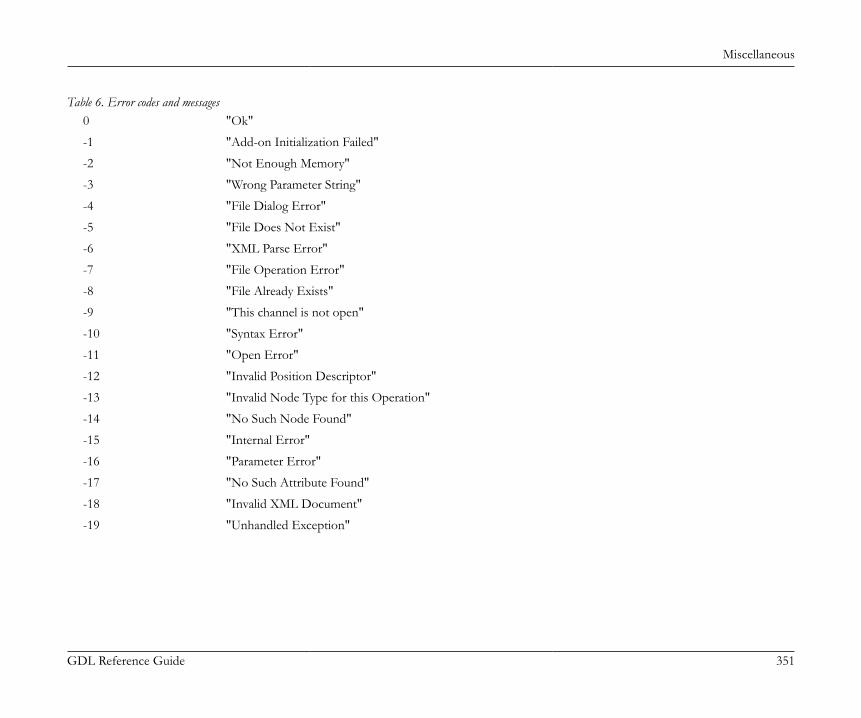
Miscellaneous
GDL Reference Guide 351
Table 6. Error codes and messages0 "Ok"
-1 "Add-on Initialization Failed"
-2 "Not Enough Memory"
-3 "Wrong Parameter String"
-4 "File Dialog Error"
-5 "File Does Not Exist"
-6 "XML Parse Error"
-7 "File Operation Error"
-8 "File Already Exists"
-9 "This channel is not open"
-10 "Syntax Error"
-11 "Open Error"
-12 "Invalid Position Descriptor"
-13 "Invalid Node Type for this Operation"
-14 "No Such Node Found"
-15 "Internal Error"
-16 "Parameter Error"
-17 "No Such Attribute Found"
-18 "Invalid XML Document"
-19 "Unhandled Exception"
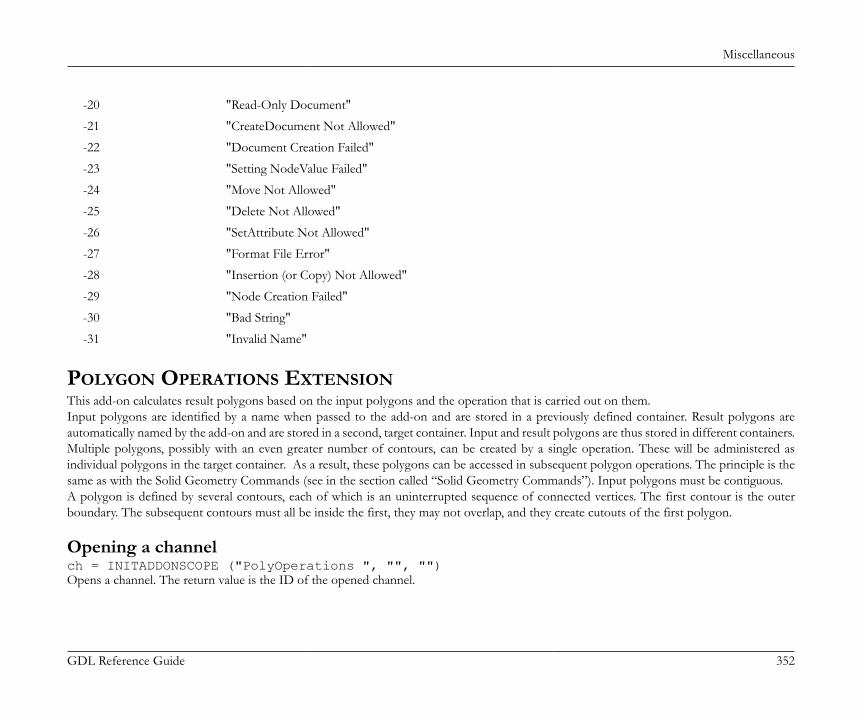
Miscellaneous
GDL Reference Guide 352
-20 "Read-Only Document"
-21 "CreateDocument Not Allowed"
-22 "Document Creation Failed"
-23 "Setting NodeValue Failed"
-24 "Move Not Allowed"
-25 "Delete Not Allowed"
-26 "SetAttribute Not Allowed"
-27 "Format File Error"
-28 "Insertion (or Copy) Not Allowed"
-29 "Node Creation Failed"
-30 "Bad String"
-31 "Invalid Name"
POLYGON OPERATIONS EXTENSIONThis add-on calculates result polygons based on the input polygons and the operation that is carried out on them.Input polygons are identified by a name when passed to the add-on and are stored in a previously defined container. Result polygons areautomatically named by the add-on and are stored in a second, target container. Input and result polygons are thus stored in different containers.Multiple polygons, possibly with an even greater number of contours, can be created by a single operation. These will be administered asindividual polygons in the target container. As a result, these polygons can be accessed in subsequent polygon operations. The principle is thesame as with the Solid Geometry Commands (see in the section called “Solid Geometry Commands”). Input polygons must be contiguous.A polygon is defined by several contours, each of which is an uninterrupted sequence of connected vertices. The first contour is the outerboundary. The subsequent contours must all be inside the first, they may not overlap, and they create cutouts of the first polygon.
Opening a channelch = INITADDONSCOPE ("PolyOperations ", "", "")Opens a channel. The return value is the ID of the opened channel.
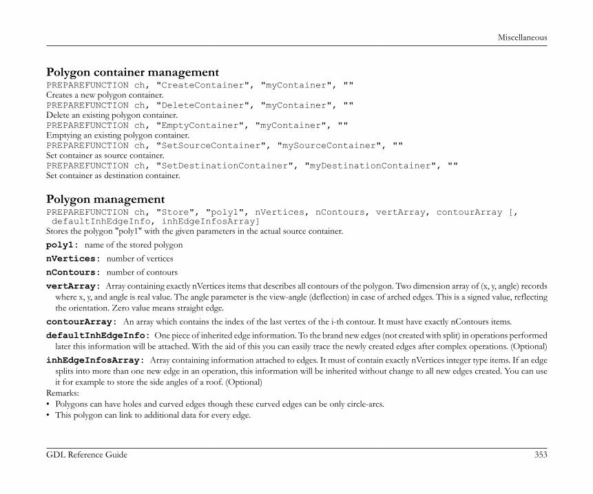
Miscellaneous
GDL Reference Guide 353
Polygon container managementPREPAREFUNCTION ch, "CreateContainer", "myContainer", ""Creates a new polygon container.PREPAREFUNCTION ch, "DeleteContainer", "myContainer", ""Delete an existing polygon container.PREPAREFUNCTION ch, "EmptyContainer", "myContainer", ""Emptying an existing polygon container.PREPAREFUNCTION ch, "SetSourceContainer", "mySourceContainer", ""Set container as source container.PREPAREFUNCTION ch, "SetDestinationContainer", "myDestinationContainer", ""Set container as destination container.
Polygon managementPREPAREFUNCTION ch, "Store", "poly1", nVertices, nContours, vertArray, contourArray [, defaultInhEdgeInfo, inhEdgeInfosArray]Stores the polygon "poly1" with the given parameters in the actual source container.poly1: name of the stored polygonnVertices: number of verticesnContours: number of contoursvertArray: Array containing exactly nVertices items that describes all contours of the polygon. Two dimension array of (x, y, angle) records
where x, y, and angle is real value. The angle parameter is the view-angle (deflection) in case of arched edges. This is a signed value, reflectingthe orientation. Zero value means straight edge.
contourArray: An array which contains the index of the last vertex of the i-th contour. It must have exactly nContours items.defaultInhEdgeInfo: One piece of inherited edge information. To the brand new edges (not created with split) in operations performed
later this information will be attached. With the aid of this you can easily trace the newly created edges after complex operations. (Optional)inhEdgeInfosArray: Array containing information attached to edges. It must of contain exactly nVertices integer type items. If an edge
splits into more than one new edge in an operation, this information will be inherited without change to all new edges created. You can useit for example to store the side angles of a roof. (Optional)
Remarks:• Polygons can have holes and curved edges though these curved edges can be only circle-arcs.• This polygon can link to additional data for every edge.
Miscellaneous
GDL Reference Guide 354
• The first vertex must be always repeated in the last for all contours. So in this representation, a triangle have four vertices, where the firstand the last vertex is identical.
• The first contour is the main contour, and it must contain the others.PREPAREFUNCTION ch, "Dispose", "poly1", "myContainer"Deletes the polygon "poly1" from the container "myContainer".
Polygon operation settingsPREPAREFUNCTION ch, "HalfPlaneParams", "", ca, cb, ccSet the half plane in 2D to be used in the "PolyCut" operation.Defining inequality for the half plane: ca * x + cb * y > cc.ca: Coefficient of xcb: Coefficient of ycc: ConstantPREPAREFUNCTION ch, "OffsetParams", "", itemIdx, offsetValueSet the offset parameters used in "OffsetEdge" and "ResizeContour" operation.itemIdx: Index of the edge to be translated (for "OffsetEdge" operation). Index of the resizable contour (for "ResizeContour" operation).offsetValue: Distance of the translation. Negative and positive offset values make the edge move inside and outside, respectively. If the
offset is big, the neighboring vertices can be cut out.
Polygon operationsIn the following polygon operations the "poly1" and "poly2" source polygons are located in the source polygon container. The resulting polygonsare stored in the destination polygon container with an unique name started with "resPolygonID", where "ID" is a number.dim resPolyIDArray[]nPgon = CALLFUNCTION (ch, "poly1 OP poly2", "", resPolyIDArray)Executes the "OP" operation with "poly1" and "poly2" polygons and puts the new values into the given parameters. The return value is thenumber of the generated polygonsOP: can be:+: Polygon addition-: Polygon subtraction/: Polygon intersection
resPolyIDArray: Array of resulting polygon identifiers.
Miscellaneous
GDL Reference Guide 355
Copying a polygon from the source container to the destination containerdim resPolyIDArray[]nPgon = CALLFUNCTION (ch, "CopyPolygon", "poly1", resPolyIDArray)Regularizing a polygon - Making it geometrically valid.dim resPolyIDArray[]nPgon = CALLFUNCTION (ch, "Regularize", "poly1", resPolyIDArray)A polygon is valid if• Its first boundary contains all the others• Is oriented correctly (the main contour is a positively oriented curve, the rest is oriented negatively)• Has no self-intersections• Its area is not zero• Has no zero length edgesIntersecting the polygon with a halfplane.The halfplane must be set with an "HalfPlaneParams" command. The result will be regularized.dim resPolyIDArray[]nPgon = CALLFUNCTION (ch, "PolyCut", "poly1", resPolyIDArray)Translating an edge of a polygon perpendicularly to its direction.The edge index and translation offset must be set with an "OffsetParams" command. The result will be regularized.dim resPolyIDArray[]nPgon = CALLFUNCTION (ch, "OffsetEdge", "poly1", resPolyIDArray)Enlarges or shrinks a contour of a polygon.The contour index and translation offset must be set with an "OffsetParams" command. The result will be regularized.dim resPolyIDArray[]nPgon = CALLFUNCTION (ch, "ResizeContour", "poly1", resPolyIDArray)
Get resulting polygonsGetting all polygon names from the actual source container.dim resPolyIDArray[]nPgon = CALLFUNCTION (ch, "GetSourcePolygons", "", resPolyIDArrayGetting all polygon names from the actual destination container.dim resPolyIDArray[]nPgon = CALLFUNCTION (ch, "GetDestinationPolygons", "", resPolyIDArray)Getting the resulting polygon vertices after any polygon operation call.The polygon with name "polygonID" located in the destination polygon container.
Miscellaneous
GDL Reference Guide 356
dim resVertices[]nVertices = CALLFUNCTION (ch, "GetVertices", polygonID, resVertices)Getting the resulting polygon contour end indices after any polygon operation call.The polygon with name "polygonID" located in the destination polygon container.dim contArr[]nContours = CALLFUNCTION (ch, "GetContourEnds", polygonID, contArr)Getting the resulting polygon edge informations after any polygon operation call.dim inhEdgeInfosArr[]nEdgeInfos = CALLFUNCTION (ch, "GetInhEdgeInfos", polygonID, inhEdgeInfosArr)The polygon with name "polygonID" located in the destination polygon container.
Closing channelCLOSEADDONSCOPE (ch)Closes channel "ch". Deletes all of the stored polygons.
Index
GDL Reference Guide 357
INDEX
SYNTAX LISTING OF GDL COMMANDS
AABS (x)
ACS (x)
ADD dx, dy, dz
ADD2 x, y
ADDGROUP (g_expr1, g_expr2)
ADDGROUP{2} (g_expr1, g_expr2, edgeColor, materialId, materialColor)
ADDX dx
ADDY dy
ADDZ dz
APPLICATION_QUERY (extension_name, parameter_string, variable1, variable2, ...)
ARC r, alpha, beta
ARC2 x, y, r, alpha, beta
ARMC r1, r2, l, h, d, alpha
ARME l, r1, r2, h, d
ASN (x)
ATN (x)
Index
GDL Reference Guide 358
BBASE
BEAM left_material, right_material, vertical_material, top_material, bottom_material, height, x1, x2, x3, x4, y1, y2, y3, y4, t, mask1, mask2, mask3, mask4
BINARY mode [, section]
BINARYPROP
BITSET (x, b [, expr])
BITTEST (x, b)
BLOCK a, b, c
BODY status
BPRISM_ top_material, bottom_material, side_material, n, h, radius, x1, y1, s1, ... xn, yn, sn
BREAKPOINT expression
BRICK a, b, c
BWALL_ left_material, right_material, side_material, height, x1, x2, x3, x4, t, radius, mask1, mask2, mask3, mask4, n, x_start1, y_low1, x_end1, y_high1, frame_shown1, ..., x_startn, y_lown, x_endn, y_highn, frame_shownn, m, a1, b1, c1, d1,
Index
GDL Reference Guide 359
..., am, bm, cm, dm
CCALL macro_name_string [,] PARAMETERS [ALL][name1=value1, ... namen=valuen][[,] RETURNED_PARAMETERS r1, r2, ...]
CALL macro_name_string [,]PARAMETERS value1 or DEFAULT [, ... valuen or DEFAULT]
CALL macro_name_string [, parameter_list]
CALLFUNCTION (channel, function_name, parameter, variable1 [, variable2, ...])
CEIL (x)
CIRCLE r
CIRCLE2 x, y, r
CLOSE channel
CLOSEADDONSCOPE channel
COMPONENT name, quantity, unit [, proportional_with, code, keycode, unitcode]
CONE h, r1, r2, alpha1, alpha2
COONS n, m, mask, x11, y11, z11, ... x1n, y1n, z1n, x21, y21, z21, ... x2n, y2n, z2n, x31, y31, z31, ... x3m, y3m, z3m, x41, y41, z41, ... x4m, y4m, z4m
COOR wrap, vert1, vert2, vert3, vert4
COS (x)
Index
GDL Reference Guide 360
CPRISM_ top_material, bottom_material, side_material, n, h, x1, y1, s1, ... xn, yn, sn
CPRISM_{2} top_material, bottom_material, side_material, n, h, x1, y1, alpha1, s1, mat1, ..., xn, yn, alphan, sn, matn
CREATEGROUPWITHMATERIAL (g_expr, repl_directive, pen, material)
CROOF_ top_material, bottom_material, side_material, n, xb, yb, xe, ye, height, angle, thickness, x1, y1, alpha1, s1, ..., xn, yn, alphan, sn
CROOF_{2} top_material, bottom_material, side_material, n, xb, yb, xe, ye, height, angle thickness, x1, y1, alpha1, s1, mat1, ... xn, yn, alphan, sn, matn
CSLAB_ top_material, bottom_material, side_material, n, h, x1, y1, z1, s1, ... xn, yn, zn, sn
CUTFORM n, method, status, rx, ry, rz, d, x1, y1, mask1, [mat1,] ... xn, yn, maskn [, matn]
CUTPLANE [x [, y [, z [, side [, status]]]]][statement1 ... statementn]CUTEND
Index
GDL Reference Guide 361
CUTPLANE{2} angle [, status][statement1 ... statementn]CUTEND
CUTPLANE{3} [x [, y [, z [, side [, status]]]]][statement1 ... statementn]CUTEND
CUTPOLY n, x1, y1, ... xn, yn [, x, y, z][statement1statement2...statementn]CUTEND
CUTPOLYA n, status, d, x1, y1, mask1, ... xn, yn, maskn [, x, y, z][statement1statement2...statementn]CUTEND
CUTSHAPE d [, status][statement1 statement2 ... statementn]CUTEND
CWALL_ left_material, right_material, side_material, height, x1, x2, x3, x4, t, mask1, mask2, mask3, mask4, n, x_start1, y_low1, x_end1, y_high1, frame_shown1,
Index
GDL Reference Guide 362
..., x_startn, y_lown, x_endn, y_highn, frame_shownn, m, a1, b1, c1, d1, ..., am, bm, cm, dm
CYLIND h, r
DDATABASE_SET set_name [, descriptor_name, component_name, unit_name, key_name, criteria_name, list_set_name]
DEFINE EMPTY_FILL name [[,] FILLTYPES_MASK fill_types]
DEFINE FILL name [[,] FILLTYPES_MASK fill_types,] pattern1, pattern2, pattern3, pattern4, pattern5, pattern6, pattern7, pattern8, spacing, angle, n, frequency1, direction1, offset_x1, offset_y1, m1, length11, ... length1m, ... frequencyn, directionn, offset_xn, lengthn1, ... lengthnm
DEFINE FILLA name [,] [FILLTYPES_MASK fill_types,] pattern1, pattern2, pattern3, pattern4, pattern5, pattern6, pattern7, pattern8, spacing_x, spacing_y, angle, n, frequency1, directional_offset1, direction1, offset_x1, offset_y1, m1, length11, ... length1m, ... frequencyn, directional_offsetn, directionn,
Index
GDL Reference Guide 363
offset_xn, offset_yn, mn, lengthn1, ... lengthnm
DEFINE IMAGE_FILL name image_name [[,] FILLTYPES_MASK fill_types] part1, part2, part3, part4, part5, part6, part7, part8, image_vert_size, image_hor_size, image_mask, image_rotangle
DEFINE LINEAR_GRADIENT_FILL name [[,] FILLTYPES_MASK fill_types]
DEFINE LINE_TYPE name spacing, n, length1, ... lengthn
DEFINE MATERIAL name type, surface_red, surface_green, surface_blue [, ambient_ce, diffuse_ce, specular_ce, transparent_ce, shining, transparency_attenuation [, specular_red, specular_green, specular_blue, emission_red, emission_green, emission_blue, emission_att]] [, fill_index [, fillcolor_index, texture_index]]
DEFINE MATERIAL name [,] BASED_ON orig_name [,] PARAMETERS name1 = expr1 [, ...] [[,] ADDITIONAL_DATA name1 = expr1 [, ...]]
DEFINE RADIAL_GRADIENT_FILL name [[,] FILLTYPES_MASK fill_types]
DEFINE SOLID_FILL name [[,] FILLTYPES_MASK fill_types]
DEFINE STYLE name font_family, size, anchor, face_code
DEFINE STYLE{2} name font_family, size, face_code
DEFINE SYMBOL_FILL name [,][FILLTYPES_MASK fill_types,] pat1, pat2, pat3, pat4, pat5, pat6, pat7, pat8, spacingx1, spacingy1, spacingx2, spacingy2, angle, scaling1, scaling2, macro_name [,] PARAMETERS [name1 = value1, ... namen = valuen]
DEFINE SYMBOL_LINE name dash, gap, macro_name PARAMETERS [name1 = value1, ...
Index
GDL Reference Guide 364
namen = valuen]
DEFINE TEXTURE name expression, x, y, mask, angle
DEFINE TRANSLUCENT_FILL name [[,] FILLTYPES_MASK fill_types] pat1, pat2, pat3, pat4, pat5, pat6, pat7, pat8, percentage
DEL n [, begin_with]
DEL TOP
DELETED_PAR_VALUE (oldparname, outputvalue)
DESCRIPTOR name [, code, keycode]
DIM var1[dim_1], var2[dim_1][dim_2], var3[ ], var4[ ][ ], var5[dim_1][ ], var5[ ][dim_2]
DO [statment1 statement2 ... statementn]WHILE condition
DRAWINDEX number
DRAWING
DRAWING2 [expression]
DRAWING3 projection_code, angle, method
DRAWING3{2} projection_code, angle, method [, backgroundColor, fillOrigoX, fillOrigoY, filldirection]
DRAWING3{3} projection_code, angle, method, parts [, backgroundColor, fillOrigoX, fillOrigoY, filldirection][[,] PARAMETERS name1=value1, ... namen=valuen]

Index
GDL Reference Guide 365
EEDGE vert1, vert2, pgon1, pgon2, status
ELBOW r1, alpha, r2
ELLIPS h, r
END [v1, v2, ..., vn]
EXIT [v1, v2, ..., vn]
EXP (x)
EXTRUDE n, dx, dy, dz, mask, x1, y1, s1, ..., xn, yn, sn
EXTRUDEDSHELL topMat, bottomMat, sideMat_1, sideMat_2, sideMat_3, sideMat_4, defaultMat, n, offset, thickness, flipped, trimmingBody, x_tb, y_tb, x_te, y_te, topz, tangle, x_bb, y_bb, x_be, y_be, bottomz, bangle, preThickenTran_11, preThickenTran_12, preThickenTran_13, preThickenTran_14, preThickenTran_21, preThickenTran_22, preThickenTran_23, preThickenTran_24, preThicakenTran_31, preThickenTran_32, preThickenTran_33, preThickenTran_34, x_1, y_1, s_1, ... x_n, y_n, s_n
FFILE_DEPENDENCE "name1" [, "name2", ...]
FOR variable_name = initial_value TO end_value [ STEP step_value ] NEXT variable_name
FPRISM_ top_material, bottom_material, side_material, hill_material,
Index
GDL Reference Guide 366
n, thickness, angle, hill_height, x1, y1, s1, ..., xn, yn, sn
FRA (x)
FRAGMENT2 fragment_index, use_current_attributes_flag
FRAGMENT2 ALL, use_current_attributes_flag
GGET (n)
GOSUB label
GOTO label
GROUP "name" [statement1 ... statementn]ENDGROUP
HHIDEPARAMETER name1 [, name2, ..., namen]
HIDEPARAMETER ALL [name1 [, name2, ..., namen]]
HOTARC r, alpha, beta, unID
HOTARC2 x, y, r, startangle, endangle
HOTLINE x1, y1, z1, x2, y2, z2, unID
HOTLINE2 x1, y1, x2, y2
HOTSPOT x, y, z [, unID [, paramReference, flags] [, displayParam]]
HOTSPOT2 x, y [, unID [, paramReference, flags] [, displayParam]]
HPRISM_ top_mat, bottom_mat, side_mat,
Index
GDL Reference Guide 367
hill_mat, n, thickness, angle, hill_height, status, x1, y1, s1, ..., xn, yn, sn
IIF condition THEN labelIF condition GOTO labelIF condition GOSUB label
IF condition THEN statement [ELSE statement]
IF condition THEN [statement1 statement2 ... statementn][ELSE statementn+1 statementn+2 ... statementn+m]ENDIF
IND (MATERIAL, name_string
IND (FILL, name_string)
IND (LINE_TYPE, name_string)
IND (STYLE, name_string)
IND (TEXTURE, name_string)
INITADDONSCOPE (extension, parameter_string1, parameter_string2)
Index
GDL Reference Guide 368
INPUT (channel, recordID, fieldID, variable1 [, variable2, ...])
INT (x)
ISECTGROUP (g_expr1, g_expr2)
ISECTGROUP{2} (g_expr1, g_expr2, edgeColor, materialId, materialColor)
ISECTLINES (g_expr1, g_expr2)
KKILLGROUP g_expr
L[LET] varnam = n
LGT (x)
LIBRARYGLOBAL (object_name, parameter, value)
LIGHT red, green, blue, shadow, radius, alpha, beta, angle_falloff, distance1, distance2, distance_falloff [[,] ADDITIONAL_DATA name1 = value1, name2 = value2, ...]
LINE2 x1, y1, x2, y2
LINE_PROPERTY expr
LIN_ x1, y1, z1, x2, y2, z2
LOCK name1 [, name2, ..., namen]
LOCK ALL [name1 [, name2, ..., namen]]
LOG (x)
Index
GDL Reference Guide 369
MMASS top_material, bottom_material, side_material, n, m, mask, h, x1, y1, z1, s1, ... xn, yn, zn, sn, xn+1, yn+1, zn+1, sn+1, ... xn+m, yn+m, zn+m, sn+m
MAX (x1, x2, ... xn)
MESH a, b, m, n, mask, z11, z12, ... z1m, z21, z22, ... z2m, ... zn1, zn2, ... znm
MIN (x1, x2, ... xn)
MODEL WIRE
MODEL SURFACE
MODEL SOLID
MUL mx, my, mz
MUL2 x, y
MULX mx
MULY my
MULZ mz
NNEWPARAMETER name, type [, dim1 [, dim2]]
Index
GDL Reference Guide 370
NOT (x)
NSP
NTR ()
OOPEN (filter, filename, parameter_string)
OUTPUT channel, recordID, fieldID, expression1 [, expression2, ...]
PPARAGRAPH name alignment, firstline_indent, left_indent, right_indent, line_spacing [, tab_position1, ...] [PEN index] [[SET] STYLE style1] [[SET] MATERIAL index] 'string1' 'string2' ... 'string n' [PEN index] [[SET] STYLE style2] [[SET] MATERIAL index] 'string1' 'string2' ... 'string n' ...ENDPARAGRAPH
PARAMETERS name1 = expression1 [, name2 = expression2, ...,
Index
GDL Reference Guide 371
namen = expressionn]
PEN n
PGON n, vect, status, edge1, edge2, ... edgen
PGON{2} n, vect, status, wrap, edge_or_wrap1, ..., edge_or_wrapn
PI
PICTURE expression, a, b, mask
PICTURE2 expression, a, b, mask
PICTURE2{2} expression, a, b, mask
PIPG expression, a, b, mask, n, vect, status, edge1, edge2, ... edgen
PLACEGROUP g_expr
PLANE n, x1, y1, z1, ... xn, yn, zn
PLANE_ n, x1, y1, z1, s1, ... xn, yn, zn, sn
POLY n, x1, y1, ... xn, yn
POLY2 n, frame_fill, x1, y1, ... xn, yn
POLY2_ n, frame_fill, x1, y1, s1, ... xn, yn, sn
POLY2_A n, frame_fill, fill_pen, x1, y1, s1, ..., xn, yn, sn
POLY2_B n, frame_fill, fill_pen, fill_background_pen, x1, y1, s1, ..., xn, yn, sn
POLY2_B{2} n, frame_fill, fill_pen, fill_background_pen, fillOrigoX, fillOrigoY, fillAngle,
Index
GDL Reference Guide 372
x1, y1, s1, ..., xn, yn, sn
POLY2_B{3} n, frame_fill, fill_pen, fill_background_pen, fillOrigoX, fillOrigoY, mxx, mxy, myx, myy, x1, y1, s1, ..., xn, yn, sn
POLY2_B{4} n, frame_fill, fill_pen, fill_background_pen, fillOrigoX, fillOrigoY, mxx, mxy, myx, myy, gradientInnerRadius, x1, y1, s1, ..., xn, yn, sn
POLY2_B{5} n, frame_fill, fillcategory, distortion_flags, fill_pen, fill_background_pen, fillOrigoX, fillOrigoY, mxx, mxy, myx, myy, gradientInnerRadius, x1, y1, s1, ..., xn, yn, sn
POLYROOF defaultMat, k, m, n, offset, thickness, applyContourInsidePivot, z_1, ... z_k, pivotX_1, pivotY_1, pivotMask_1, roofAngle_11, gableOverhang_11, topMat_11, bottomMat_11, ... roofAngle_1k, gableOverhang_1k, topMat_1k, bottomMat_1k, ... pivotX_m, pivotY_m, pivotMask_m, roofAngle_m1, gableOverhang_m1, topMat_m1, bottomMat_m1, ... roofAngle_mk, gableOverhang_mk, topMat_mk, bottomMat_mk, contourX_1, contourY_1, contourMask_1, edgeTrim_1, edgeAngle_1, edgeMat_1, ...
Index
GDL Reference Guide 373
contourX_n, contourY_n, contourMask_n, edgeTrim_n, edgeAngle_n, edgeMat_n
POLY_ n, x1, y1, s1, ... xn, yn, sn
POSITION position_keyword
PREPAREFUNCTION channel, function_name, expression1 [, expression2, ...]
PRINT expression [, expression, ...]
PRISM n, h, x1, y1, ... xn, yn
PRISM_ n, h, x1, y1, s1, ... xn, yn, sn
PROJECT2 projection_code, angle, method
PROJECT2{2} projection_code, angle, method [, backgroundColor, fillOrigoX, fillOrigoY, filldirection]
PROJECT2{3} projection_code, angle, method, parts [, backgroundColor, fillOrigoX, fillOrigoY, filldirection][[,] PARAMETERS name1=value1, ... namen=valuen]
PUT expression [, expression, ...]
PYRAMID n, h, mask, x1, y1, s1, ... xn, yn, sn
RRADIUS radius_min, radius_max
RECT a, b
RECT2 x1, y1, x2, y2
REF COMPONENT code [, keycode [, numeric_expression]]
REF DESCRIPTOR code [, keycode]
REPEAT [statement1 statement2 ...
Index
GDL Reference Guide 374
statementn]UNTIL condition
REQ (parameter_string)
REQUEST (question_name, name | index, variable1 [, variable2, ...])
RESOL n
RETURN
REVOLVE n, alpha, mask, x1, y1, s1, ... xn, yn, sn
REVOLVEDSHELL topMat, bottomMat, sideMat_1, sideMat_2, sideMat_3, sideMat_4, defaultMat, n, offset, thickness, flipped, trimmingBody, alphaOffset, alpha, preThickenTran_11, preThickenTran_12, preThickenTran_13, preThickenTran_14, preThickenTran_21, preThickenTran_22, preThickenTran_23, preThickenTran_24, preThickenTran_31, preThickenTran_32, preThickenTran_33, preThickenTran_34, x_1, y_1, s_1, ... x_n, y_n, s_n
REVOLVEDSHELLANGULAR topMat, bottomMat, sideMat_1, sideMat_2, sideMat_3, sideMat_4, defaultMat, n, offset, thickness, flipped, trimmingBody, alphaOffset, alpha, segmentationType, nOfSegments, preThickenTran_11, preThickenTran_12, preThickenTran_13, preThickenTran_14, preThickenTran_21, preThickenTran_22, preThickenTran_23, preThickenTran_24, preThickenTran_31, preThickenTran_32, preThickenTran_33, preThickenTran_34, x_1, y_1, s_1, ... x_n, y_n, s_n
Index
GDL Reference Guide 375
REVOLVE{2} n, alphaOffset, alpha, mask, sideMat, x1, y1, s1, mat1, ... xn, yn, sn, matn
RICHTEXT x, y, height, 0, textblock_name
RICHTEXT2 x, y, textblock_name
RND (x)
ROT x, y, z, alpha
ROT2 alpha
ROTX alphax
ROTY alphay
ROTZ alphaz
ROUND_INT (x)
RULED n, mask, u1, v1, s1, ... un, vn, sn, x1, y1, z1, ... xn, yn, zn
RULEDSHELL topMat, bottomMat, sideMat_1, sideMat_2, sideMat_3, sideMat_4, defaultMat, n, m, g, offset, thickness, flipped, trimmingBody, preThickenTran_11, preThickenTran_12, preThickenTran_13, preThickenTran_14, preThickenTran_21, preThickenTran_22, preThickenTran_23, preThickenTran_24, preThickenTran_31, preThickenTran_32, preThickenTran_33, preThickenTran_34, firstpolyX_1, firstpolyY_1, firstpolyS_1, ... firstpolyX_n, firstpolyY_n, firstpolyS_n, secondpolyX_1, secondpolyY_1, secondpolyS_1, ... secondpolyX_m, secondpolyY_m, secondpolyS_m, profile2Tran_11, profile2Tran_12, profile2Tran_13, profile2Tran_14
Index
GDL Reference Guide 376
profile2Tran_21, profile2Tran_22, profile2Tran_23, profile2Tran_24 profile2Tran_31, profile2Tran_32, profile2Tran_33, profile2Tran 34 generatrixFirstIndex_1, generatrixSecondIndex_1, ... generatrixFirstIndex_g, generatrixSecondIndex_g
RULED{2} n, mask, u1, v1, s1, ... un, vn, sn, x1, y1, z1, ... xn, yn, zn
SSECT_ATTRS fill, fill_background_pen, fill_pen, contour_pen [, line_type]
SECT_FILL fill, fill_background_pen, fill_pen, contour_pen
[SET] STYLE name_string
[SET] STYLE index
[SET] MATERIAL name_string
[SET] MATERIAL index
[SET] FILL name_string
[SET] FILL index
[SET] LINE_TYPE name_string
[SET] LINE_TYPE index
SETMIGRATIONGUID guid
SGN (x)
SHADOW casting [, catching]
SIN (x)
Index
GDL Reference Guide 377
SLAB n, h, x1, y1, z1, ... xn, yn, zn
SLAB_ n, h, x1, y1, z1, s1, ... xn, yn, zn, sn
SPHERE r
SPLINE2 n, status, x1, y1, angle1, ..., xn, yn, anglen
SPLINE2A n, status, x1, y1, angle1, length_previous1, length_next1, ... xn, yn, anglen, length_previousn, length_nextn
SPLIT (string, format, variable1 [, variable2, ..., variablen])
SPRISM_ top_material, bottom_material, side_material, n, xb, yb, xe, ye, h, angle, x1, y1, s1, ... xn, yn, sn
SPRISM_{2} top_material, bottom_material, side_material, n, xtb, ytb, xte, yte, topz, tangle, xbb, ybb, xbe, ybe, bottomz, bangle, x1, y1, s1, mat1, ..., xn, yn, sn, matn
SQR (x)
STR (numeric_expression, length, fractions)
STR (format_string, numeric_expression)
STRLEN (string_expression)
STRSTR (string_expression1, string_expression2)
STRSUB (string_expression, start_position, characters_number)
STR{2} (format_string, numeric_expression [, extra_accuracy_string])
Index
GDL Reference Guide 378
STW (string_expression)
SUBGROUP (g_expr1, g_expr2)
SUBGROUP{2} (g_expr1, g_expr2, edgeColor, materialId, materialColor)
SURFACE3D ()
SWEEP n, m, alpha, scale, mask, u1, v1, s1, ... un, vn, sn, x1, y1, z1, ... xm, ym, zm
SWEEPGROUP (g_expr, x, y, z)
SWEEPGROUP{2} (g_expr, x, y, z)
SWEEPGROUP{3} (g_expr, x, y, z, edgeColor, materialId, materialColor, method)
TTAN (x)
TEVE x, y, z, u, v
TEXT d, 0, expression
TEXT2 x, y, expression
TEXTBLOCK name width, anchor, angle, width_factor, charspace_factor, fixed_height, 'string_expr1' [, 'string_expr2', ...]
TEXTBLOCK_ name width, anchor, angle, width_factor, charspace_factor, fixed_height, 'string_expr1' [, 'string_expr2', ...]
TOLER d
TUBE n, m, mask, u1, w1, s1, ... un, wn, sn, x1, y1, z1, angle1,
Index
GDL Reference Guide 379
... xm, ym, zm, anglem
TUBEA n, m, mask, u1, w1, s1, ... un, wn, sn, x1, y1, z1, ... xm, ym, zm
UUI_BUTTON type, text, x, y [, width, height, id [, url]]
UI_BUTTON type, text, x, y, width, height [, id [, url]] [ UI_TOOLTIP tooltiptext ]
UI_CURRENT_PAGE index
UI_DIALOG title [, size_x, size_y]
UI_GROUPBOX text, x, y, width, height
UI_INFIELD "name", x, y, width, height [, method, picture_name, images_number, rows_number, cell_x, cell_y, image_x, image_y, expression_image1, text1, ..., expression_imagen, textn]
UI_INFIELD "name", x, y, width, height [, extra parameters ... ] [ UI_TOOLTIP tooltiptext ]
UI_INFIELD{2} name, x, y, width, height [, method, picture_name, images_number,
Index
GDL Reference Guide 380
rows_number, cell_x, cell_y, image_x, image_y, expression_image1, text1, ..., expression_imagen, textn]
UI_INFIELD{2} name, x, y, width, height [, extra parameters ... ] [ UI_TOOLTIP tooltiptext ]
UI_INFIELD{3} name, x, y, width, height [, method, picture_name, images_number, rows_number, cell_x, cell_y, image_x, image_y, expression_image1, text1, value_definition1, ..., expression_imagen, textn, value_definitionn]
UI_INFIELD{3} name, x, y, width, height [, extra parameters ... ] [ UI_TOOLTIP tooltiptext ]
UI_OUTFIELD expression, x, y [, width, height [, flags]]
UI_OUTFIELD expression, x, y, width, height [, flags] [ UI_TOOLTIP tooltiptext ]
UI_PAGE page_number
UI_PICT picture_reference, x, y [, width, height [, mask]]
UI_PICT expression, x, y [, width, height [, mask]] [ UI_TOOLTIP tooltiptext ]
UI_PICT_BUTTON type, text, picture_reference, x, y, width, height [, id [, url]]
UI_PICT_BUTTON type, text, picture_reference, x, y, width, height [, id [, url]] [ UI_TOOLTIP tooltiptext ]
UI_RADIOBUTTON name, value, text, x, y, width, height
UI_RADIOBUTTON name, value, text, x, y, width, height [ UI_TOOLTIP tooltiptext ]
Index
GDL Reference Guide 381
UI_SEPARATOR x1, y1, x2, y2
UI_STYLE fontsize, face_code
USE (n)
VVALUES "parameter_name" [,]value_definition1 [, value_definition2, ...]
VALUES "fill_parameter_name" [[,] FILLTYPES_MASK fill_types,] value_definition1 [, value_definition2, ...]
VARDIM1 (expr)
VARDIM2 (expr)
VARTYPE (expression)
VECT x, y, z
VERT x, y, z
VOLUME3D ()
WWALLARC2 x, y, r, alpha, beta
WALLBLOCK2 n, fill_control, fill_pen, fill_background_pen, fillOrigoX, fillOrigoY, fillAngle, x1, y1, s1, ... xn, yn, sn
WALLBLOCK2{2} n, frame_fill, fillcategory, distortion_flags, fill_pen, fill_background_pen, fillOrigoX, fillOrigoY, mxx, mxy, myx, myy, innerRadius, x1, y1, s1, ..., xn, yn, sn
Index
GDL Reference Guide 382
WALLHOLE n, status, x1, y1, mask1, ... xn, yn, maskn [, x, y, z]
WALLHOLE2 n, fill_control, fill_pen, fill_background_pen, fillOrigoX, fillOrigoY, fillAngle, x1, y1, s1, ... xn, yn, sn
WALLHOLE2{2} n, frame_fill, fillcategory, distortion_flags, fill_pen, fill_background_pen, fillOrigoX, fillOrigoY, mxx, mxy, myx, myy, innerRadius, x1, y1, s1, ..., xn, yn, sn
WALLLINE2 x1, y1, x2, y2
WALLNICHE n, method, status, rx, ry, rz, d, x1, y1, mask1, [mat1,] ... xn, yn, maskn[, matn]
WHILE condition DO [statement1 statement2 ... statementn]ENDWHILE
Index
GDL Reference Guide 383
XXFORM a11, a12, a13, a14, a21, a22, a23, a24, a31, a32, a33, a34
XWALL_ left_material, right_material, vertical_material, horizontal_material, height, x1, x2, x3, x4, y1, y2, y3, y4, t, radius, log_height, log_offset, mask1, mask2, mask3, mask4, n, x_start1, y_low1, x_end1, y_high1, frame_shown1, ..., x_startn, y_lown, x_endn, y_highn, frame_shownn, m, a1, b1, c1, d1, ..., am, bm, cm, dm, status
XWALL_{2} left_material, right_material, vertical_material, horizontal_material, height, x1, x2, x3, x4, y1, y2, y3, y4, t, radius, log_height, log_offset, mask1, mask2, mask3, mask4, n, x_start1, y_low1, x_end1, y_high1, sill_depth1, frame_shown1, ...,
Index
GDL Reference Guide 384
x_startn, y_lown, x_endn, y_highn, sill_depthn, frame_shownn, m, a1, b1, c1, d1, ..., am, bm, cm, dm, status