gas well/water well contamination - confex principles of the cement bond log cement bond log...
TRANSCRIPT
8/24/2013
1
GAS WELL/WATER WELL SUBSURFACE CONTAMINATION
Rick RailsbackProfessional Geoscientist
CURA Environmental & Emergency Services
“And ye shall know the truth and the truth shall make you free.”
• Oil companies –“it has never been proven that an oil or gas well has contaminated an aquifer.”
“And ye shall know the truth and the truth shall make you free.”
• Environmentalists – “every oil and gas well has contaminated all our aquifers.”
“And ye shall know the truth and the truth shall make you free.”
• Oil companies – “it has never been proven that an oil or gas well has contaminated an aquifer.”
• Environmentalists – “every oil and gas well has contaminated all our aquifers.”
The Physical System

8/24/2013
2
Well Geometry(view looking down on the wellhead)
Jet Perforation
Well Site during Frac Litigation Support
• Tools & methods for investigation
• Generally presented from
simplest tools to more complex
least expensive to most expensive
Plan for Investigation
• Proximity
• Timing of the impact
• Other contaminant sources
• Oil & gas well records
• Pressure data from the gas well
• Pressure data from the water well
Plan for Investigation
• Data on frac geometry
• Natural gas composition
• Condensate composition
• Water composition
• Seismic data
• Cement bond logs
8/24/2013
3
Wireline Logging Truck Wireline Logging Tool
Well Log Plan for Investigation
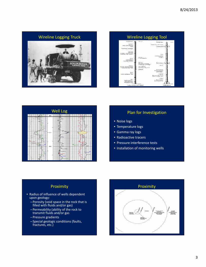
• Noise logs
• Temperature logs
• Gamma ray logs
• Radioactive tracers
• Pressure interference tests
• Installation of monitoring wells
Proximity
• Radius of influence of wells dependent upon geology:–Porosity (void space in the rock that is filled with fluids and/or gas)
–Permeability (ability of the rock to transmit fluids and/or gas
–Pressure gradients–Special geologic conditions (faults, fractures, etc.)
Proximity

8/24/2013
4
Timing
• Water well installation
• Gas well installation:– Spud date
– Surface casing set
– Vertical casing set
– Horizontal well completed & casing set
– Frac job and flow back
– Production
• Time of impact to water well
Timing
Other Contaminant Sources
• A variety of other sources may be available
• Common sources are usually shallow – within 50 feet of surface
• Impact to deeper aquifers from shallow sources unlikely due to shallow water table & impermeable layers
• Minor amounts of methane occur naturally in aquifers & may be generated by organics in the water well & equipment
Other Contaminant Sources
Oil & Gas Well Records
• W‐1 Drilling Permit Application
• G‐1 or W‐2 ‐ Gas or Oil Well Completion Test
• G‐5 Gas Well Classification Report
• Railroad Commission Online Research
–http://www.rrc.state.tx.us/data/index.php
• Railroad Commission Public GIS Map Viewer
–http://gis2.rrc.state.tx.us/public/startit.htm
8/24/2013
5
Pressure Data from Gas Well Pressure Data from Water Well
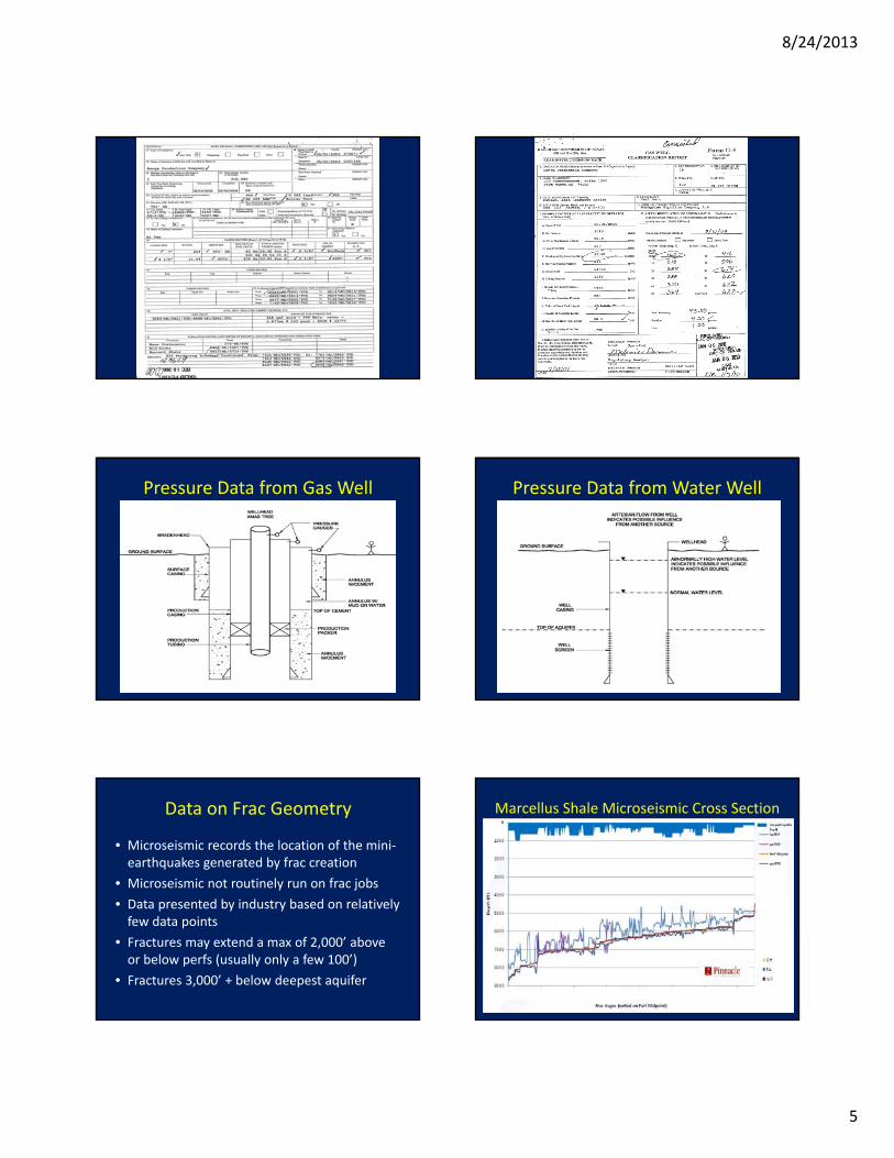
Data on Frac Geometry
• Microseismic records the location of the mini‐earthquakes generated by frac creation
• Microseismic not routinely run on frac jobs
• Data presented by industry based on relatively few data points
• Fractures may extend a max of 2,000’ above or below perfs (usually only a few 100’)
• Fractures 3,000’ + below deepest aquifer
Marcellus Shale Microseismic Cross Section
8/24/2013
6
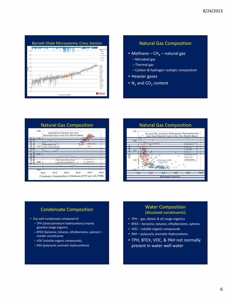
Barnett Shale Microseismic Cross Section Natural Gas Composition
• Methane – CH4 – natural gas–Microbial gas
– Thermal gas
–Carbon & hydrogen isotopic composition
• Heavier gases
• N2 and CO2 content
Natural Gas Composition Natural Gas Composition
Condensate Composition
• Gas well condensate composed of:
– TPH (total petroleum hydrocarbons) mainly gasoline range organics
– BTEX (benzene, toluene, ethylbenzene, xylenes) –marker constituents
– VOC (volatile organic compounds)
– PAH (polycyclic aromatic hydrocarbons)
Water Composition(dissolved constituents)
• TPH ‐ gas, diesel, & oil range organics
• BTEX – benzene, toluene, ethylbenzene, xylenes
• VOC – volatile organic compounds
• PAH – polycyclic aromatic hydrocarbons
• TPH, BTEX, VOC, & PAH not normally present in water well water
8/24/2013
7
Water Composition(dissolved constituents)
• Methane – CH4 – natural gas– Lab analysis for methane & other gases
– Flame ionization detector with carbon filter
–Methane meter
– Explosimeter
– Light it?
–Methane not normally present in high concentrations in water well water
Water Composition(dissolved constituents)
• Minerals & salts – naturally occurring
• TDS (total dissolved solids) & chlorides measure dissolved minerals & salts in water
• TDS – total dissolved solids– Water wells (500 – 1,800 ppm)
– Gas wells (typically > 20,000 ppm)
• Chlorides– Water wells (20 ‐ 500 ppm)
– Gas wells (typically > 20,000 ppm)
Seismic Data
• Seismic or sound waves used to image the subsurface
• Analogous to sonograms
• Gas accumulations give a “bright spot” amplitude anomaly
• 3D seismic is available over most oilfields
Seismic “Bright Spots”
Seismic Data (Potential Problems)
• Timing of data acquisition relative to gas accumulation
• Seismic data focus may not yield useable data in shallow subsurface
• Zone of gas accumulation too thin for seismic resolution
• “Bright spot” not a unique solution for gas
Cement Bond Logs
• Acoustic (sonic) device utilizes sound waves to image
• Analogous to sonograms• Free pipe returns a much greater amplitude signal than cemented pipe
• Amplitude display• VDL (variable density log) display

8/24/2013
8
Principles of the Cement Bond Log Cement Bond Log Presentation
Noise Logs (Sound Surveys)
• Sensor is an underwater microphone (hydrophone)
• Will detect flow within wellbore or behind pipe
• Turbulent fluid flow
• Gas expansion
• Disturbance of gas/liquid interface
Noise Logs (Sound Surveys)
Noise Logs (Sound Surveys) Temperature Logs
• Temperature increases with depth – normal geothermal gradient
• Anomalies created by fluids or gas entering wellbore or annulus or exiting into formation
• Identify zones producing or taking fluid
• Evaluating cement jobs
• Evaluating frac jobs
8/24/2013
9
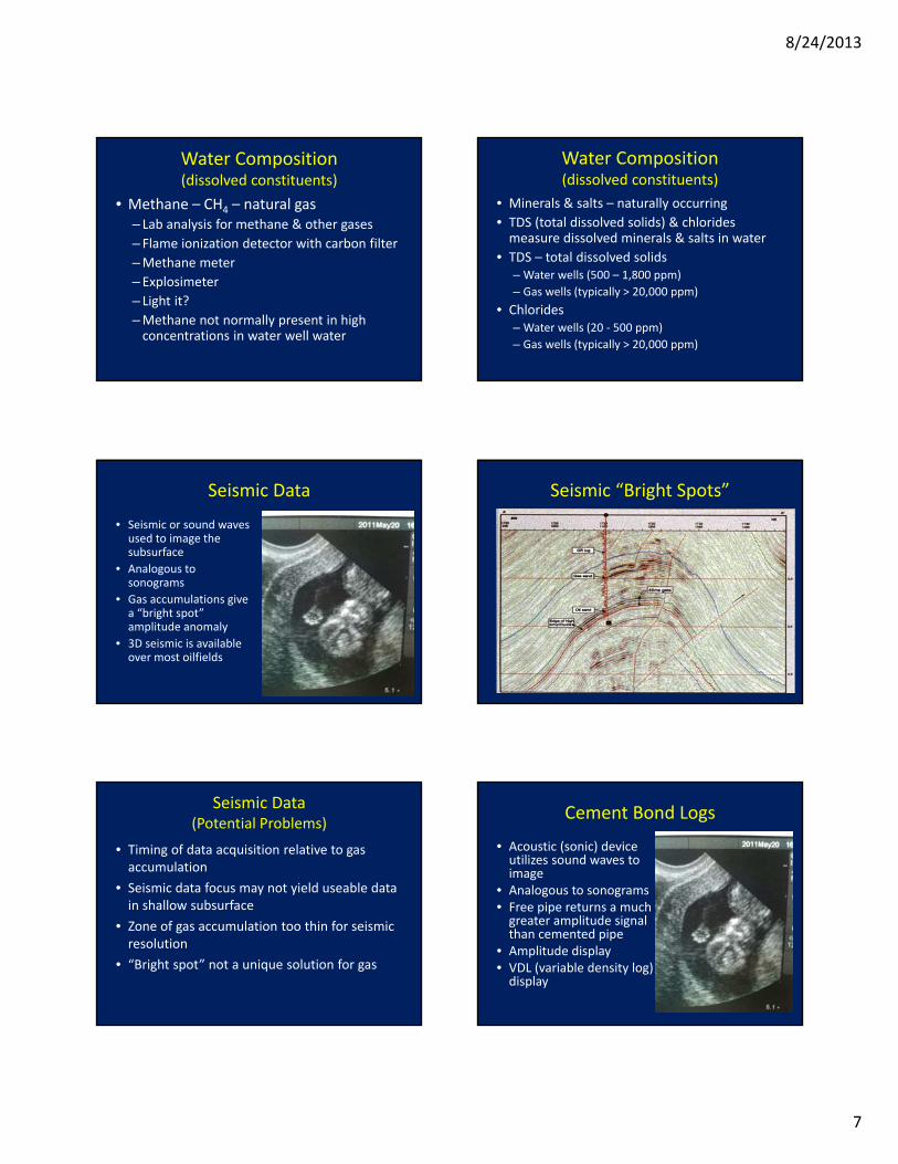
Temperature Logs
• EPA Underground Injection Control (UIC) program approves temperature logs to demonstrate well mechanical integrity –
“no significant fluid movement into an underground source of drinking water through vertical channels adjacent to the injection wellbore”.
Temperature Logs
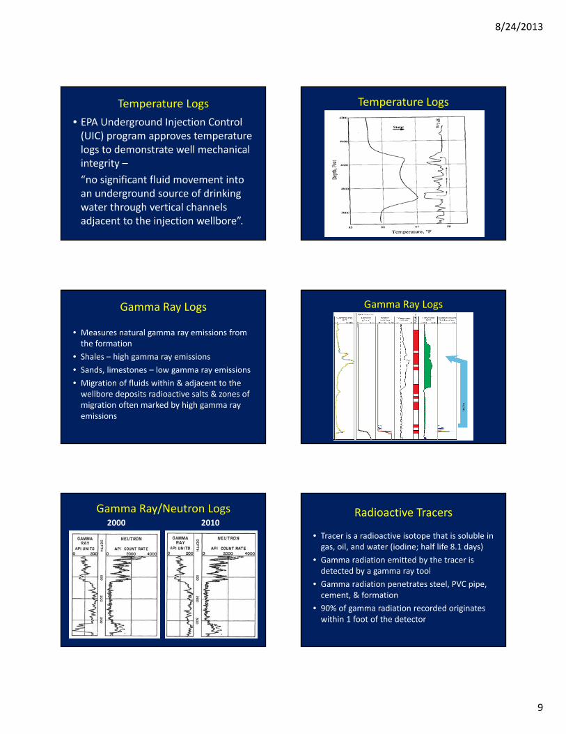
Gamma Ray Logs
• Measures natural gamma ray emissions from the formation
• Shales – high gamma ray emissions
• Sands, limestones – low gamma ray emissions
• Migration of fluids within & adjacent to the wellbore deposits radioactive salts & zones of migration often marked by high gamma ray emissions
Gamma Ray Logs
Gamma Ray/Neutron Logs2000 2010
Radioactive Tracers
• Tracer is a radioactive isotope that is soluble in gas, oil, and water (iodine; half life 8.1 days)
• Gamma radiation emitted by the tracer is detected by a gamma ray tool
• Gamma radiation penetrates steel, PVC pipe, cement, & formation
• 90% of gamma radiation recorded originates within 1 foot of the detector
8/24/2013
10
Radioactive Tracers
• Tool can inject tracer and record gamma emissions simultaneously
• Fluid movement & velocity & volume can be monitored within a well, behind casing, & between wells
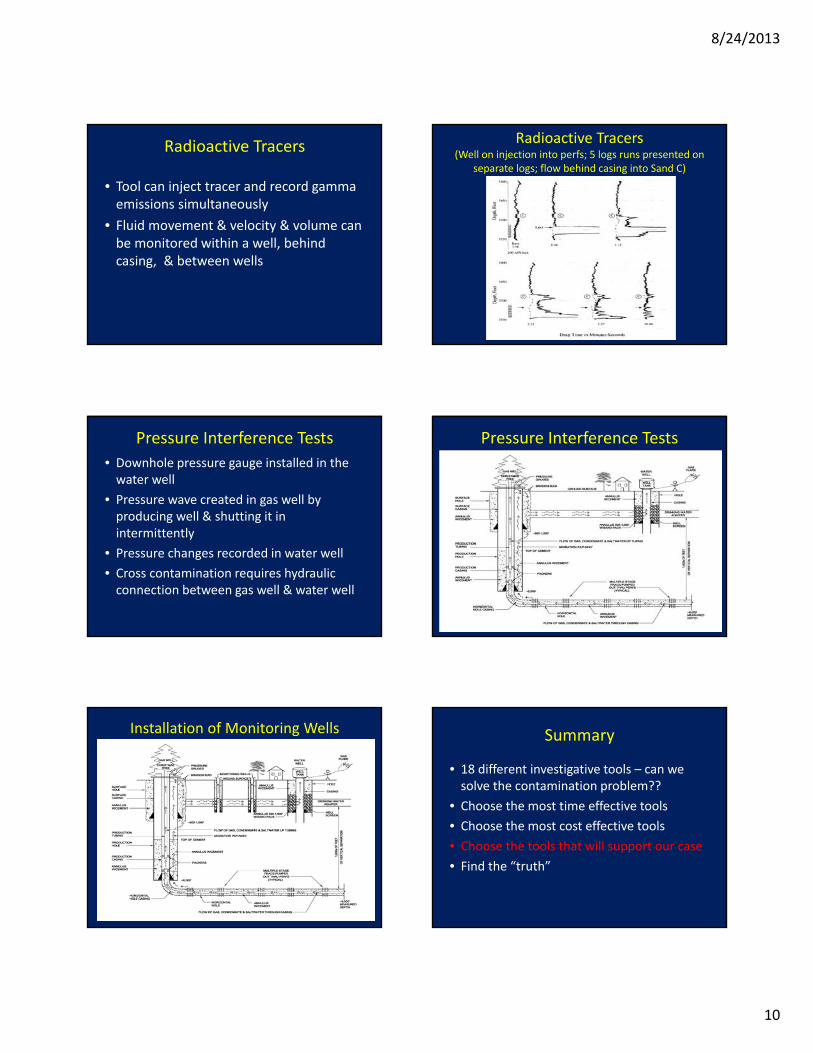
Radioactive Tracers(Well on injection into perfs; 5 logs runs presented on
separate logs; flow behind casing into Sand C)
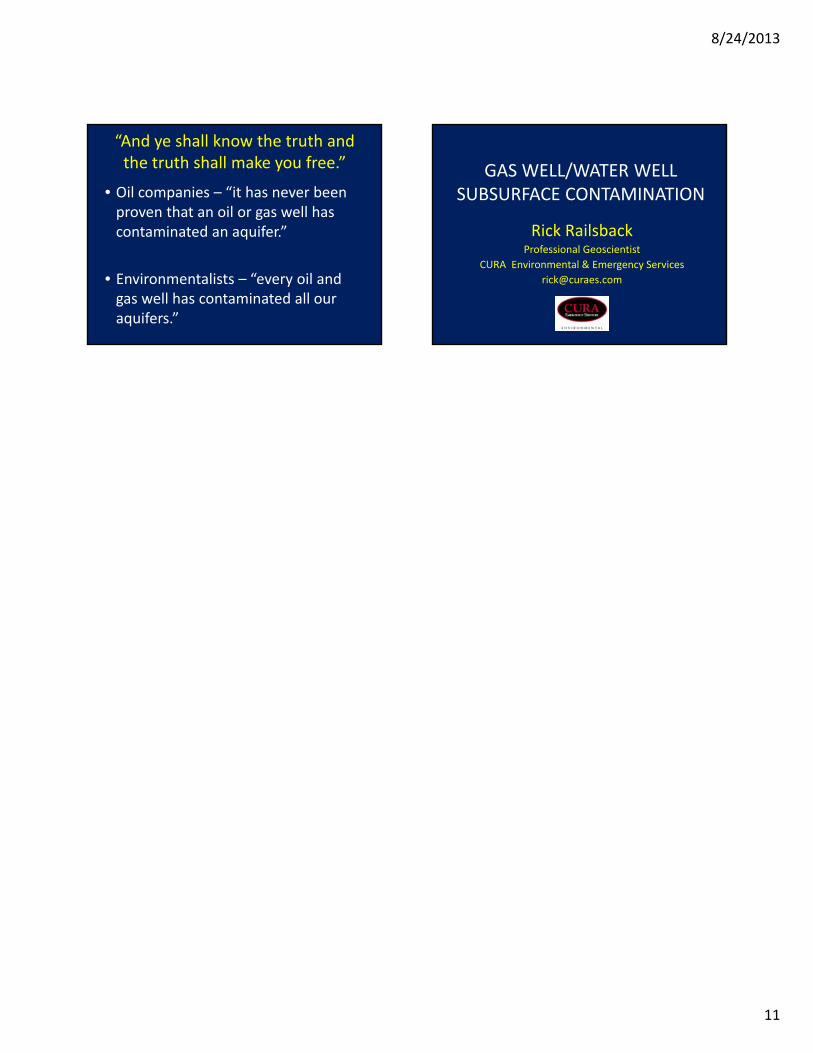
Pressure Interference Tests
• Downhole pressure gauge installed in the water well
• Pressure wave created in gas well by producing well & shutting it in intermittently
• Pressure changes recorded in water well
• Cross contamination requires hydraulic connection between gas well & water well
Pressure Interference Tests
Installation of Monitoring Wells Summary
• 18 different investigative tools – can we solve the contamination problem??
• Choose the most time effective tools
• Choose the most cost effective tools
• Choose the tools that will support our case
• Find the “truth”
8/24/2013
11
“And ye shall know the truth and the truth shall make you free.”
• Oil companies – “it has never been proven that an oil or gas well has contaminated an aquifer.”
• Environmentalists – “every oil and gas well has contaminated all our aquifers.”
GAS WELL/WATER WELL SUBSURFACE CONTAMINATION
Rick RailsbackProfessional Geoscientist
CURA Environmental & Emergency Services