gas sampling - uis. · pdf filemud logging. fluorescence is the ability of a substance to emit...
TRANSCRIPT
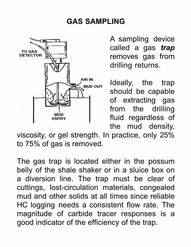
GAS SAMPLING
A sampling devicecalled a gas trapremoves gas fromdrilling returns.
Ideally, the trapshould be capableof extracting gasfrom the drillingfluid regardless ofthe mud density,
viscosity, or gel strength. In practice, only 25%to 75% of gas is removed.
The gas trap is located either in the possumbelly of the shale shaker or in a sluice box ona diversion line. The trap must be clear ofcuttings, lost-circulation materials, congealedmud and other solids at all times since reliableHC logging needs a consistent flow rate. Themagnitude of carbide tracer responses is agood indicator of the efficiency of the trap.

MUD SAMPLING
Mud samples are usually caught at the sametime as cuttings. Consistency of procedure,cleanliness of containers and avoidance of gasand oil evaporation are the key samplingproblems.
CUTTINGS SAMPLING
Cuttings are used to determine thestratigraphic interval, estimate reservoircharacteristics, and identify gas and oilsaturated intervals.
Special samples should be taken whenevergas-in-mud levels increase and one lag(estimated as pump stroke) after a drillingbreak.
Rapid processing of samples for gas and oilanalysis is essential to avoid fluid loss byevaporation.
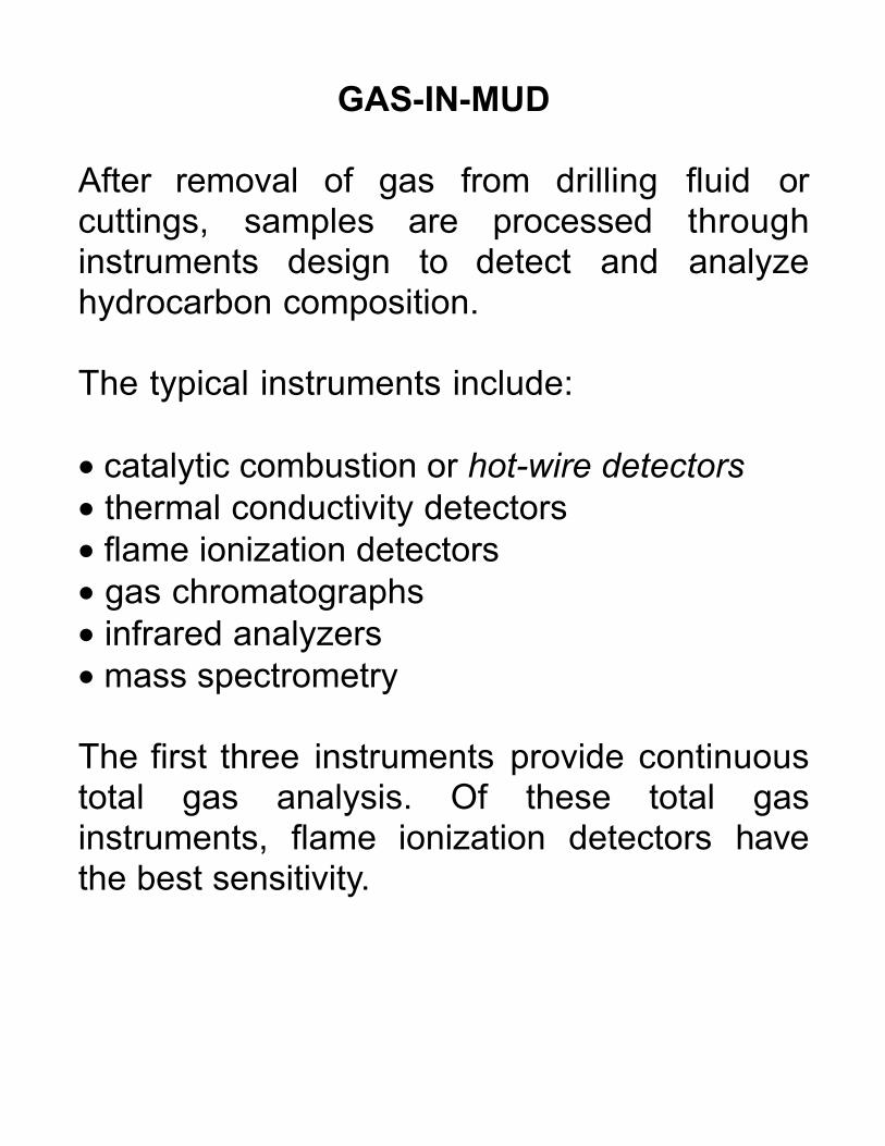
GAS-IN-MUD
After removal of gas from drilling fluid orcuttings, samples are processed throughinstruments design to detect and analyzehydrocarbon composition.
The typical instruments include:
• catalytic combustion or hot-wire detectors• thermal conductivity detectors• flame ionization detectors• gas chromatographs• infrared analyzers• mass spectrometry
The first three instruments provide continuoustotal gas analysis. Of these total gasinstruments, flame ionization detectors havethe best sensitivity.

OIL-IN-MUD
At low gas-oil ratios, gas-in-mud analysis maynot detect oil reservoirs. Friable reservoirs maytotally disaggregate and fail to provide anycomposite chips to show oil staining.
In these circumstances, oil-in-mud analysismay be the only basis for recognizing oilsaturation.
Oil can sometimes be seen in drilling fluid as acolour sheen or as globules on the surfaceafter dilution with water. Examination of thediluted mud sample under ultraviolet light mayalso detect oil as a surface fluorescence.
Procedures are available to distill out the oilfraction for liquid-liquid chromatography orinfrared analyzers.

GAS-IN-CUTTINGS
Fresh cuttings are routinely examined for gascontent. A measured weight of sample chips ispulverized in a fixed amount of water.
The vapour above the pulverized slurry isanalyzed with at total gas detector. Theresulting readings are logged as cuttings gasor microgas. Note is also made of any oil filmor globules on the surface of the slurry.
Significant amounts of gas-in-cuttings arecharacteristic of gas saturation in lowpermeability rocks.

OIL-IN-CUTTINGS
Procedures for detecting and evaluating oil-in-cuttings include:
• hydrocarbon odour• description of oil staining• ultraviolet fluorescence• solvent cut test• acid (HCl) test• hot water immersion• pyrolysis chromatography• iridescence
HYDROCARBON ODOUR
Very small amounts of HC can be detected byodour under favourable conditions. Becauseodour can dissipate rapidly, immediateevaluation is best. Sample descriptions shouldrecord odour in fresh cuttings as "none","slight", "fair" or "good".

OIL STAINING
Oil-in-cuttings is indicated by a colourationcalled staining. The colour and nature of thestain depends on the nature of the oil.
Low-gravity oils tend to stain dark brown orblack. Light oils stains can be almostcolourless.
Samples are examined immediately afterrecovery and while still wet. A binocularmicroscope with standard illumination sourceused in conjunction with standard colourcharts is recommended for consistency.
Distribution of the stain with respect to grains,pores and fracture surfaces etc should berecorded.
Description of oil staining is not wellstandardized and comparisons are difficult butsome estimate of the percentage of stainedchips should be made.

FLUORESCENCE
Fluorescence has been used as a detectionmethod for crude oil since the earliest days ofmud logging. Fluorescence is the ability of asubstance to emit light after absorbingelectromagnetic energy from an externalsource.
All crude oils fluoresce (because they containcyclic and polycyclic HCs or asphaltenes.These compounds are most abundant inaromatic crudes and least abundant inparaffinic crudes. The intensity of fluorescencedepends on both composition andconcentration.
The colour of fluorescence can be used toroughly estimate API gravity since thefluorescence wavelength decreases as APIgravity increases.
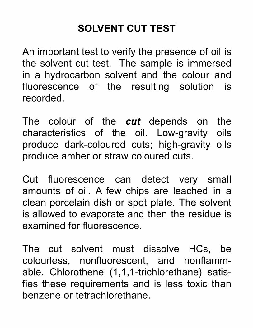
SOLVENT CUT TEST
An important test to verify the presence of oil isthe solvent cut test. The sample is immersedin a hydrocarbon solvent and the colour andfluorescence of the resulting solution isrecorded.
The colour of the cut depends on thecharacteristics of the oil. Low-gravity oilsproduce dark-coloured cuts; high-gravity oilsproduce amber or straw coloured cuts.
Cut fluorescence can detect very smallamounts of oil. A few chips are leached in aclean porcelain dish or spot plate. The solventis allowed to evaporate and then the residue isexamined for fluorescence.
The cut solvent must dissolve HCs, becolourless, nonfluorescent, and nonflamm-able. Chlorothene (1,1,1-trichlorethane) satis-fies these requirements and is less toxic thanbenzene or tetrachlorethane.

ACID TEST
Stain in carbonates and calcareous sands canbe detected by immersing cuttings in dilute(15%) HCl. Bubbles will float oil-stained chips,unstained chips remain submerged.
HOT WATER TEST
Immersion of unwashed cuttings in hot (>75oC)water may release oil to float as a film than canbe detected with ultraviolet light.
PYROLYSIS CHROMATOGRAPHY
Heating cuttings and passing the gasesthrough a chromatograph can detect lowconcentrations of HC in low permeability rocks.
IRIDESCENCE
Iridescence on wet cuttings without apparentstaining can indicate the presence of light oilor condensate.

CUTTINGS TRANSPORT
Ideally, cuttings would be recovered in thesame order with the same composition as theywere cut. This does not happen becauseparticles travel at different velocities in theannulus.
The spread of arrival times for material cut atthe same time is minimized by the use of highdensity muds with the minimum gel strengthnecessary to keep the cuttings in suspension.
Spread depends on particle size, shape anddensity. The largest particles are usually fromborehole wall caving. The smallest particlesare likely to be the result of recirculation.
The location of the diversion line for samplingcuttings can be used to eliminate largeparticles from caving and avoid recirculatedfines.

CUTTINGS EXAMINATION
The AAPG Sample Examination Manualprovides a standard for cuttings description.The manual lists the items to be recorded, aset of standard abbreviations and arecommended order in which items shouldappear.
The more important items in the AAPGrecommended order are:
LOGGED ITEMS EXAMPLESRock Type SS SLTST LS
Color LT GRY-BUFF GRY-BRN LT BRN
Hardness FM V FRI SFT
Grain Size MED GR F GR C GR
Sorting PR SRTD W SRTRD MOD SRTD
Cementation/Matrix NO CMT SIL CMT CALC CMT
Porosity NO VIS POR INT GRAN POR FR POR
Stain OIL STN DK OIL STN LT OIL STN
Fluorescence YEL-BRN FLOR M-DK BRN FLOR YEL FLOR
Cut RPD AMBER CUT WEAK LT BRN CUT DK STRAW CUT
Cut Fluorescence BRT YEL CUT FLOR GOLD CUT FLOR BLU WH CUT FLOR

SIGNIFICANCE OF SHOWS
The significance of an oil or gas show dependson a large number of factors including:
• Formation oil and gas content
interval porosity, interval saturation, hole diameter
• Flushing
overbalance, mud filtrate mobility, formation permeability,drill bit design (jets), drilling rate
• Mud volume
circulation rate, drilling rate
• Reservoir P-T conditions
volume changes moving to surface
• Retained oil saturation
oil retained in cuttings and not released to mud

GAS LOG ZEROS
For calibration purposes, the CCD (catalyticcombustion detector) true zero (or pure airbackground) is found by passing a stream ofair through the filament chamber.
During a trip, the drillstring is removed fromthe hole, usually to replace a bit or for coring.Drilling and circulation are halted for asignificant period. Cold and stagnant muddegasses with time and the total gas recorderapproaches the pure air background.
When circulation is resumed, the total gasrises as system sources of all kinds contributeto the recorded level. This level is the systembackground gas.
When a connection is made (new pipeconnected), circulation ceases and the gas logrecords a reduced level used as a systemzero.

TRIP GAS AND CONNECTION GAS
When a trip occurs the swabbing (pumping)action of the rods causes production frompreviously drilled intervals. When circulation isrestarted after a trip a slug of accumulatedproduction called trip gas is moved to thesurface.
It is normal practice to carry out a carbide testafter a trip by adding acetylene-generatingcalcium carbide to the mud. This tracer travelsdown the drillstem to the bit and up theannulus back to surface. The trip gas mustarrive ahead of the carbide test.
Diesel is often added to drilling mud as alubricant. This appears after one lag as anincrease in total gas making necessary to re-establish the system background.
Gas production during a connection appearsafter one lag and can thus be recognized asconnection gas rather than a show.

KELLY CUT
After a trip and sometimes after a connection,the drillstring may not be full of mud and aslug of air is pumped around the circulationsystem.
The air is compressed as it moves downholeand produces a slug on aerated mud in theannulus. The aerated mud scavenges gas andresults in an increase in the total gas recordedat surface.
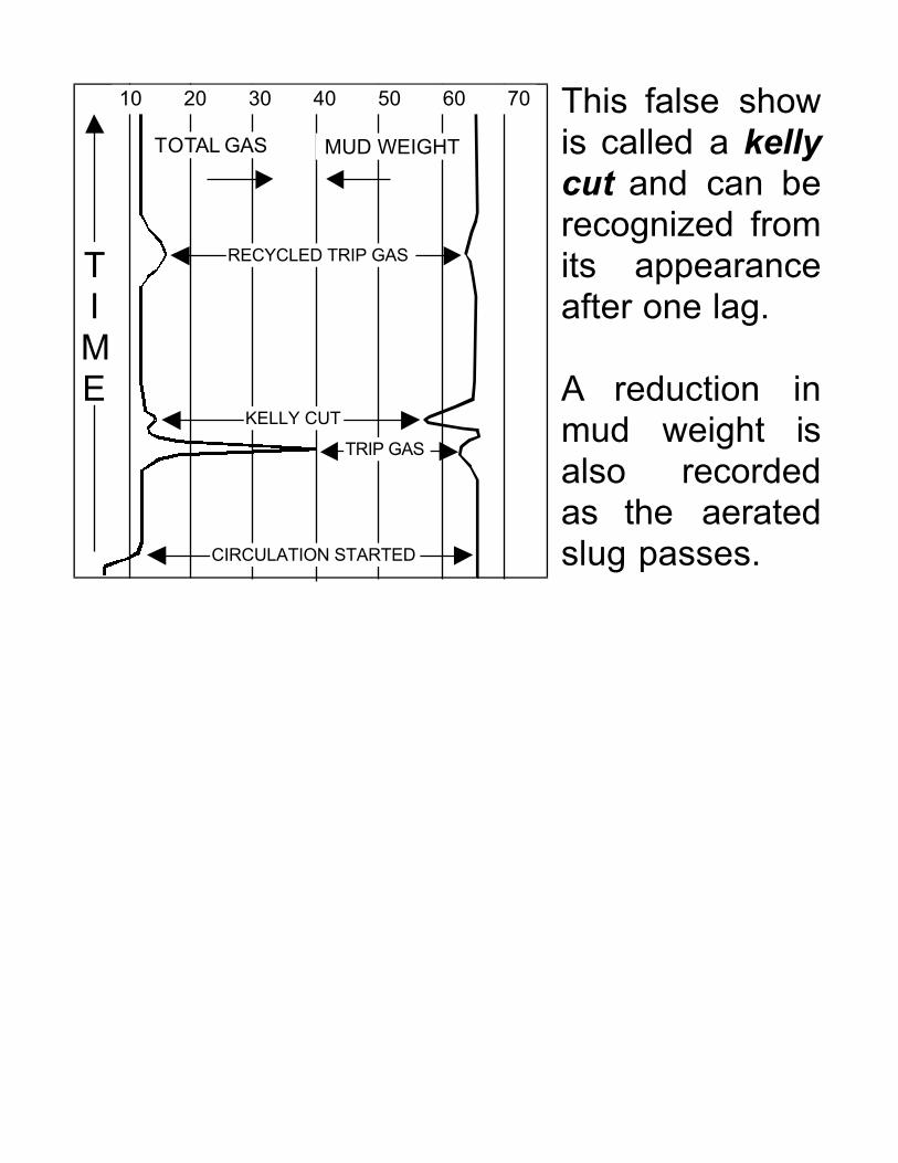
This false showis called a kellycut and can berecognized fromits appearanceafter one lag.
A reduction inmud weight isalso recordedas the aeratedslug passes.
TIME
TOTAL GAS MUD WEIGHT
10 20 30 40 50 60 70
TRIP GAS
KELLY CUT
RECYCLED TRIP GAS
CIRCULATION STARTED

TOTAL GAS LOG

A gas show is a total gas peak that cannot beattributed to one of the many system relatedevents that can produce false shows.

DRY GAS SHOW
Reservoirs saturated with gas:• increase in gas-in-mud• lack of oil stain in cuttings• little or no fluorescence• absence of oil-in-mud• high methane ratios C1:C2, C1:C3, .....• good penetration rate• visible porosity
The log shows three reservoirs at A, B, and C:• A is a dry gas sand reservoir• B is a water sand reservoir• C is a gas-bearing low permeability sand.

GAS CAP OIL SHOW
An oil show in or near the gas cap of an oil orcondensate pool can be recognized by:
• increase in total gas (ditch gas)• low to moderate oil in cuttings• trace only of free oil-in-mud• high methane ratios• good penetration rate• visible porosity
Mud conductivity or salinity should bemonitored to provide evidence of a bottomwater contact.

LIGHT-MEDIUM OIL SHOW
A light-medium gravity oil show in a reservoircan be recognized by:
• moderate gas-in-mud (ditch gas)• moderate to high gas-in-cuttings• abundant free oil-in-mud• abundant free oil-in-cuttings, light oil stain• moderate methane ratios• rapid solvent cut indicating mobile oil• good penetration rate• visible porosity
As oil gravity increases C3 and C4 may exceedC2 in the chromatographic analysis, oil stainbecomes darker and solvent cut is less rapid.

HEAVY OIL SHOW
A low gravity heavy oil show in a reservoir canbe recognized by:
• low to moderate gas-in-mud• low gas-in-cuttings• trace or no oil-in-mud• fair to good oil-in-cuttings, dark oil stain• moderate to low methane ratios• slow solvent cut indicating low oil mobility• good penetration rate• visible porosity
Reverse drilling breaks in the drilling rate logindicates shale partings in the reservoir. Veryhigh drillings rates responsible for moderaterather than low gas-in-mud.

UNDERSATURATED HEAVY OIL SHOW
An undersaturated (below bubble-point) heavyoil show in a reservoir can be recognized by:
• no gas-in-mud• no gas-in cuttings• abundant free oil-in-mud• abundant free oil-in-cuttings, dark oil stain• slow solvent cut indicating low oil mobility• good penetration rate• visible porosity
The absence of gas indicates a water-wetreservoir with undersaturated oil.

TIGHT OIL SHOW
An oil show in a tight formation displays:
• low gas-in-mud peak• higher gas-in cuttings• fair oil-in-mud• fair oil-in cuttings• moderate to low methane ratios• slow solvent cut• higher crush cut indicating low perm• moderate penetration rate• no visible porosity
The drilling rate and lack of visible porositycombined with the increased crush cut are thediagnostic features of a tight formation.

MUD CAKE
The build-up of mudsolids on the boreholeface in permeableformations is called mudcake. This limits furtherinvasion of drilling fluidsinto the reservoir.
A fluid phase called mud filtrate can pass through mudcake to replace reservoir fluids in an annulus around theborehole. The mud-impregnated zone is surrounded bya larger infiltrated zone. Together these form theinvaded zone. In the flushed zone, all but residual HChas been removed.

MUD CAKE FORMATION
Mud cake is an essentialprotection for the reservoirduring drilling. When thedrilling is overbalanced,there is a radial outwardpressure gradient fromthe wellbore to theformation.
Initially mud particles invade the reservoir andbegin to form a seal. As the mud particles clogthe pores, the passage of mud filtrate is moreprogressively restricted.
Mud cake can be clearlyidentified on manywireline logs, particular-ly caliper.
Some micro-resistivitylogs are designed torespond to mud filtrate.

BOREHOLE GEOMETRY
Rotary drilling creates acavity when mud replacesthe broken formation.Borehole size and shapeis measured with a calipertool. Tools may have fromone to four arms. Eachdevice measures differentproperties.
1- or 2-armed devicesmeasure the longest axisof the hole. 3-armed toolsmeasure some averagediameter. 4-armed cali-pers record the long-axisand a short-axis at rightangles. Caliper devicesused with other wirelinetools when their responsedepends on boreholegeometry.

TEMPERATURE DISTURBANCE
Drilling fluids are normally warmer thanshallow formations and cooler than deepformations giving rise to temperaturedisturbances around the hole.
This may effect some wireline logs where theregion sensed is close to the hole (e.g. micro-resistivity).
Bottom hole temperatures change with timeand when drilling circulation is stopped theyreturn to their natural equilibrium levels.
Temperature logs in wells are mainly used for:
• determination of geothermal gradients• location of fluid inflows• location of artificially fractured zones• location of casing leaks• location of primary cement tops

STRESS DISTURBANCE
Vertical stresses are readily estimated fromdepth and specific weight:
σσσσv = γγγγ.h
Horizontal stresses are generally unknown butcan be deduced from well-wall damage indeep wells called breakouts.
The elastic stressesaround a circularopening in anaxisymmetric stressfield are readilycalculated.
In weak materials, thematerial around thewell may collapseproducing a "plastic"annulus where thestresses are reduced.

WELLBORE STABILITY
The borehole wall must support the loads fromboth the in-situ stresses and the pressure ofthe wellbore fluids. Failure can enlarge,reduce, fracture or collapse the hole.
Fracing (hydrofracture)occurs when the mudweight exceeds theeffective tangentialstress by an amountequal to the tensilestrength of the rock.
Brittle elastic failure of the rock at thecircumference of the hole occurs if the stressexceeds the compressive strength. This kind offailure is called a borehole breakout.
Plastic yield or collapse may occur in weakmaterials such as shales and unconsolidatedsands resulting in squeezing or caving.Control of mud weight can prevent wellborefailure.