gas metal arc welding machine - askaynak.com.tr€¦ · welding method and specifications gmaw...
TRANSCRIPT

3Phase
Welding Method and Specifications
GMAW (MIG/MAG)
Eczacıbaşı - Lincoln Electric recommend to use “ASKAYNAK” gas metal arc welding wire for obtaining high performance from MasterMIG 350.
Gas Metal ArcWelding Machine
USER MANUAL
US
ER
M
AN
UA
L
2 years limited spare part warranty (Clamps and cables excluded)

“AT” UYGUNLUK BEYANI“EU” DECLARATION OF CONFORMITY
Kaynak Tekniği Sanayi ve Ticaret A.Ş.İmalatçı / Manufacturer
Teknik Hizmetler Müdürü - Technical Sevices ManagerSertaç ÖZEN
Kocaeli, TURKEY
Kaynak Tekniği Sanayi ve Ticaret A.Ş.TOSB Otomotiv Yan Sanayi İhtisas Organize Sanayi Bölgesi
2. Cadde, No: 5, Şekerpınar 41420 Çayırova, Kocaeli - TURKEY
CE sertifikası yılında eklenmiştir.CE mark was first affixed in .
Ürün / Product
Marka - Model / Brand - Model
Yukarıda tanımlanan beyanın nesnesi, ilgili uyumlaştırılmış AB mevzuatı ile uyumludur.The object of the declaration described above, is in conformity with the relevant union
harmonisation legislation.
Direktifler / Directives
Uyumlaştırılmış Standartlar / Harmonised Standards
Bu uygunluk beyanı yalnızca imalatçının sorumluluğu altında düzenlenir.This declaration of conformity is issued under the sole responsability of the manufacturer.
09.03.2017
20092009
TS EN 60974-1:2013, TS EN 60974-10:2014
Gazaltı Kaynak Makinesi - GMA Welding Machine
®Askaynak MasterMIG® 350
2014/35/EU, 2014/30/EU
US
ER
M
AN
UA
L
46

US
ER
M
AN
UA
L
47
Contents
MANUFACTURER
Kaynak Tekniği Sanayi ve Ticaret A.Ş.
TOSB Otomotiv Yan Sanayi İhtisas Organize Sanayi Bölgesi 2. Cadde, No: 5, Şekerpınar 41420 Çayırova, KOCAELİ - TURKEY
Tel: (+90 262) 679 78 00 Fax: (+90 262) 679 77 00
www.askaynak.com.tr
Manufactured in People’s Republic of China byKAYNAK TEKNİĞİ SANAYİ ve TİCARET A.Ş.
Safety in Welding ................................................................................. 48 - 56
Electromagnetic Compliance ............................................................... 57 - 58
General Information ............................................................................. 59 - 60
Specifications ....................................................................................... 61 - 62
Preparations for Work .......................................................................... 63 - 66
Installation and Operation .................................................................... 67 - 69
Functions of Wire Feeder System ................................................................ 70
Environment Conditions ............................................................................... 71
GMAW (MIG/MAG) Method ......................................................................... 72
Efficient Use of Machine In Terms of Energy Consumption........................... 72
Storage and Transportation ........................................................................ 73
Unpacking ................................................................................................... 73
De-commissioning the Welding Machine ................................................... 73
Maintenance and Troubleshooting ....................................................... 74 - 77
Failures in Welding Seams ................................................................... 78 - 79
Electrical Circuit Diagram .................................................................... 80 - 81
Spare Parts .......................................................................................... 82 - 85
Warnings Label ........................................................................................... 85
Wire Feeder and Power Unit Specifications ............................................... 86
This Machines has been designed for GMAW (MIG/MAG). Shall not be used for any other purpose.
Be sure that this machine should only operated by qualified personnel. Be sure that all installation, operation, maintenance and repair procedures are performed only by authorized personnel. Be sure to read user guide carefully before operating the machine. Failure to follow the instructions included in the user guide may cause serious injury, loss of life and damage on machine. Please read the warnings next to the symbols stated below. “Kaynak Tekniği Sanayi ve Ticaret A.Ş.” is not liable for any damages due to improper connection, storage conditions and operation procedures.
WARNING: This symbol indicates that the instructions within the user guide must be followed to avoid potential serious personal injury, loss of life and damages on machine. Protect yourself and other people.
READ AND UNDERSTAND THE INSTRUCTIONS CAREFULLY: Be sure to read and understand the user guide before operating the machine. Failure to follow the instructions stated in the user guide may cause serious injury, loss of life and damage on equipment.
Do not weld while you are unattentive, unattentive, tired and sleepless.
Arc welding is a safe application when necessary measures are taken to protect the welder against potential dangers. If these measures missed or disregarded, there may be dangers such as electric shock, exposing to high levels of fume and gas, arc radiation, fire and explode which may cause serious injury or even death.
Note: For detailed information on safety in welding, please read ANSI Z49.1 standard.
Protective Equipments:
Welding operators should wear protective clothing to protect themselves against burning risk. Welding burns is a frequent risk which may be caused due to splash of welding sparks on bare skin.
Clothing used while welding may vary based on used welding method but generally it should provide easy movements and should cover welder’s body to protect against splashes, sparks and arc radiation.
Wooly clothing should be preferred due to its resistance against flame. Synthetic clothing should not be worn since they will melt when exposed to heat.
Protective clothing should be protected from grease and oil. This kind of materials may flare and burn uncontrolledly in an environment with oxygen.
Shirtsleeves and trouser hems should not be folded. Since sparks and
Safety in Welding - 1
US
ER
M
AN
UA
L
48

melted metals may enter into these folds. Trousers should be kept outside the work shoes and should not be inserted into it. Otherwise melted metals and sparks may enter into shoe.
Other protective clothing used in dangerous situations are stated below:
• Flame resistant clothing, • Gaiters, • Aprons, • Leather cuff gloves and capes, • Helmet used under the welding mask.
To protect hands against burns, cuts and scratches, gloves made from flame resistant materials such as leather must be used. In addition, to provide some insulation against electric shock, care should be taken that the gloves made from flame resistant material are in good condition and dry.
Noise:
To protect ears against sparks and melted metals and to prevent hearing impairment due to noise of arc welder, ear protectors should be used. When the noise in working environment is reached to a level that disturbing the ears and causing headache, auditory problem may occur. In such a condition immediately use your ear protectors.
Hearing impairment may not be noticed until tested and then it may be too late for treatment.
Importance and Cleanliness of Working Environment:
The tidiness and cleanliness of working environment is important as the maintenance of welder. Even the level of potential damage rises up to number of people in the environment. Although warnings related to machine are read and necessary measures are taken, any of the personnel tripping over a cable may cause electric shock, contact to hot metal or falling risk for himself, you and other people.
All equipment, cables, hoses and gas cylinders should be kept away from busy places such as doors, aisles and stairs. Care should be taken for the tidiness of the environment and when welding is completed working environment should be cleaned. By this way, both work safety and working efficiency will increase. Besides, other workers near the welding area may step into weld pool by mistake, therefore safety guards should be placed around the welding area during welding.
ELECTRIC SHOCK CAN KILL: Electric shock danger is the most serious risk that operator may encounter frequently. Contacting electrically hot parts may cause injuries, death or falling down due to electric shock and sudden reflex. While machine is operating, do not touch to the electrode, ground connection or live work piece connected to the machine. Insulate yourself against electrode, grounding connection or work piece. Immediately after
Safety in Welding - 2
US
ER
M
AN
UA
L
49

plugging out the power cable, do not touch metal ends of power cable, there may be electric shock danger.
Electric shock risk related to welding machine divides into two categories:
• Primary voltage shock (e.g. 230-460 V) • Secondary voltage shock (e.g. 20-100 V)
Primary electric shock is very dangerous since it is much higher than welding voltage. When the power to the machine is open, you can encounter with primary electric shock while your body is in contact with ground or touching a live point within the machine. Please note that turning off the ON/OFF switch located on the machine do not cut off the electric. To cut off the electric to the machine it is necessary to disconnect the supply cable from connection point or to shut down the fuse of incoming electric.
Never remove side covers of the machine and in case of failure have an authorized technician to inspect and repair it.
Be sure to ground the machine and work piece.
While installing the machine and making ground connection, follow general electric rules, all local laws and regulations and instructions of the manufacturer company.
Do not use uninsulated cables and pliers, replace with the new ones. Never dip the electrode in water for cooling.
Never simultaneously touch electrically “hot” parts of electrode holders connected to two separate welders, because voltage between the two can be the total of the open circuit voltage of both welders.
When working above floor level, use a safety belt to protect yourself from a fall should you get a shock.
In semi-automatic or automatic welding, welding wire, electrode reel, welding head, nozzle or torch are also electrically “hot”.
Always be sure the work cable makes a good electrical connection with the metal being welded. The connection should be as close as possible to the area being welded.
While the welder is electrically hot, do not insert your hand or any other object inside it.
WELDING ARC and ARC RAYS CAN BURN: Use a shield with proper filter and cover plates to protect your eyes from sparks and the rays of the arc when welding or observing open arc welding. Skin should be protected by clothing made from flame resistance material. Protect other nearby personnel with suitable, non-flammable screening and/or warn them not to watch welding arc nor expose themselves to the arc rays or to hot spatter or metal.
When eyes are exposed to UV rays even for a short time, also called as “Getting Welder’s Flash”, it may cause burns in your eyes. Getting Welder’s Flash may not be noticed after hours of exposing, but it is too irritating as well as may cause transient blindness. Normally getting welder’s flash is
Safety in Welding - 3
US
ER
M
AN
UA
L
50

a temporary situation, but exposing eyes to UV rays for a long time and frequently may cause permanent damage on eyes. As a protection measure besides not to watch arc rays, also using welding goggles having proper filter is necessary.
As a rule, welding should start with a dark colored protective filter then should continue with a lighter colored filter sufficient to see the area being welded providing that not to fall under the minimum level. Welding masks protect head, face, ears and neck against electric shock risk, heat, sparks and fire.
GASES and FUMES CAN BE DANGEREOUS : When welding with electrodes which require special ventilation such as stainless or hard facing or on lead or cadmium plated steel and other metals or coatings which produce highly toxic fumes, keep exposure as low as possible and keep the exposure level under “Minimum Limit Values” using local exhaust or mechanical ventilation. In confined spaces or in some circumstances, a respirator may be required even outdoors. Additional precautions are also required when welding on galvanized steel.
Do not weld in locations near chlorinated hydrocarbon vapors coming from degreasing, cleaning or spraying operations. The heat and rays of the arc can react with solvent vapors to form a highly toxic gas, and other irritating products.
Welding may cause fumes and gases that are injurious to health. Always enough ventilation should be used or fumes and gases should be exhausted from breathing place.
Generally in welding applications; temporary effects for short time can be seen such as face and skin burning, dizziness, nausea and fever based on exposure period and amount of fume. Long time fume exposure may cause iron loading and dysfunctions in lungs. Bronchitis and pulmonary fibrosis are primary effects occurred.
Some electrodes may include alloys that entail special ventilation. Label of these products that entails special ventilation should not be ignored and “Product Safety Information Form” reports should be read carefully. When welding on this kind of materials it may be necessary to use gas mask.
Keeping your head out of fume clouds is the easiest way for protection against toxic fumes and gases.
Avoid breathing these fumes and gases, air circulation or mechanical ventilation equipments should be used and if the ventilation is not enough gas mask should be used.
WELDING and CUTTING SPARKS CAN CAUSE FIRE OR EXPLOSION: Where compressed gases are to be used at the job site, special precautions should be used to prevent hazardous situations.
Do not heat, cut or weld tanks, drums or containers until the proper steps have been taken to insure that such procedures will not cause flammable or
Safety in Welding - 4
US
ER
M
AN
UA
L
51

toxic vapors from substances inside. Tanks, drums or containers can cause an explosion even though they have been cleaned. For information, read “Recommended Safe Practices for the Preparation for Welding and Cutting of Containers and Piping That Have Held Hazardous Substances”, AWS F4.1 from American Welding Society.
Connect work cable to the piece being welded as close as possible. Work cables connected to the building framework or other locations away from the welding area increase the possibility of the welding current passing through lifting chains, crane cables or other alternate circuits. This can create fire hazards or overheat lifting chains or cables until they fail.
Keep away fire hazards from welding area and have a fire extinguisher readily available. Remember that welding sparks and hot materials from welding operation can easily go through small cracks and openings to adjacent areas. Until ensuring that precautions are used to fully clean flammable and toxic gases, never weld any tanks, drums, containers or material. Never operate welder in places that flammable gases, vapors or liquid fuels exist.
Always keep in mind the fire risk due to high temperatures in arc welding. Welding arc temperature may increase up to 5000 C°, but generally this temperature is not the only fire reason. Fire risk may be occurred due to sparks or melted metals splashed around. These metals may splash up to ten meters away. Therefore keep inflammable materials away from welding area. Also make sure that your work piece do not contact with any material that may flare when heated. Material, that may flare with contact are divided into three categories as liquids (fuel, oil, paint, thinner etc.), solids (wood, cartoon, paper etc.) and gases (acetylene, hydrogen etc.).
Inspect the welding area. If there are systems operating with fuel or hydraulic oil and if you cannot move welding area or system, place fire-resistant protecting screen between them If you are working above floor level or on stairway, make sure there is no flammable or explosive material below. Also please remember that slag and sparks may splash on people around.
Special precautions should be used when welding in dusty environment. Dust particles may burn and may cause sudden fire or explosion. If you don’t have information about the inflammableness and fugacity of the dust in the environment, do not start welding or cutting until it is inspected and approved by expert and authorized person.
Before starting to the welding procedure, please check if there is any flammable or self-ignition under heat coating on the surface of your work piece.
When you have a break in welding process, please make sure that the electrode holder do not contact to the ground or work piece.
If you are welding within ten meters to the place where flammable materials located, have a observor near you. This observer should watch where the sparks and splashes go and should access easily to the fire extinguishers when necessary. After welding process, please check if there is any fume around for half an hour with the observer.
Safety in Welding - 5
US
ER
M
AN
UA
L
52

As in other emergency situations, first rule is not to panic in situations where welding accidents happen. According to the size of the fire, to warn the others activate the fire alarm, inform fire station, shut down the plasma cutting machine and leave the building from fire exits as soon as possible.
FIRE DANGER MAY CAUSE ACCIDENTS : To prevent the risk for every kind of arc glare and fire, never leave the welding torch on welding desk or any surface in contact with work clamp.
Never refuel near to the welding arc or if there is any engine operating in the surrounding area. Stop the engine and allow it to cool before refueling to prevent spilled fuel from vaporizing on contact with hot engine parts and igniting. While refilling the tank, do not spill fuel around.
CYLINDER MAY EXPLODE IF DAMAGED : Use only compressed gas cylinders containing the correct shielding gas for the process used and properly operating regulators designed for the gas and pressure used. All hoses, fittings, etc. should be suitable for the welding application and maintained in good condition with a proper installation.
Always keep cylinders in an upright position securely chained to an undercarriage or fixed support.
Carefully choose the locations of the cylinders:
• Cylinders should be kept away from areas where they may be struck or subjectedto physical damage.
• Cylinders should be located to a safe distance from arc welding or cutting operations and any other source of heat, sparks or flame.
Never allow the electrode, electrode holder or any other electrically “hot” parts to touch a cylinder.
Keep your head and face away from the cylinder valve outlet when opening the cylinder valve.
Valve protection caps should always be in place and hand tight except when the cylinder is in use or connected for use (including the transportation of the cylinder).
MOVING PARTS MAY HURT YOUR HANDS : Always keep all safety guards, coverings and equipments in place and maintain in good condition. Always keep your hands, hair, clothing and tools away from V-belt, gears, fans and all other moving parts when starting, operating or repairing the equipment.
In some cases, it may be necessary to remove safety guards to perform required maintenance. Remove the guards only when necessary and replace them when the maintenance requiring their removal is complete. Always use the greatest care when working near moving parts.
Never put your hands near to the cooling fan while it is operating.
To prevent accidentally starting gasoline engines while turning the engine
Safety in Welding - 6
US
ER
M
AN
UA
L
53

or welding generator during maintenance work, disconnect the spark plug wires, distributor cap or magneto wire as appropriate.
FOR ELECTRICALLY POWERED EQUIPMENT : Turn off input power using the disconnect switch at the fuse box before working on the equipment. Install equipment in accordance with local codes in force.
GROUNDING : Power cables should be connected to a well grounded plug for your safety and proper operation of the equipment.
Periodically inspect the conditions of electrode cables, supply cables and cables connected to the equipment. If you notice any improper situation, immediately replace damaged parts with the new ones. To prevent the risk for every kind of arc glare and fire, never leave the electrode holder on welding desk or any surface in contact with work clamp.
WELDED HOT MATERIAL MAY CAUSE BURNS : High amounts of heat may be produced from welding process. Hot surfaces and material may cause serious burns. While touching or moving this kind of material, always wear gloves.
ELECTRIC and MAGNETIC FIELDS MAY BE HAZARDOUS TO THE HUMAN HEALTH : Electric current flowing through any conductor causes electromagnetic fields. This electromagnetic field may interfere with devices such as pacemaker. Welders having a pacemaker shall consult their physician before operating this equipment. Exposure to electric and magnetic fields may have other health effects which are not known yet (Page 57).
COMPLIANCE WITH CE NORMS: This machine has been manufactured in compliance with the European Instructions.
SAFE OPERATION : This machine is suitable for welding in environments where there is high electric shock risk.
Not to be used in residential locations where the electrical power is provided by the public low-voltage supply system.
Safety in Welding - 7
US
ER
M
AN
UA
L
54

EXTRA SAFETY MEASURES:
In some situations applying safety measures may be difficult, but even so follow the mentioned rules. Keep your gloves dry, if getting wet is unavoidable then have an extra pair of gloves near you. Stand on a plywood, plastic mat or similar dry and insulating material. Insulate your body from welding piece.
If welding must be performed under electrically hazardous conditions such as in damp locations or while wearing wet clothing, on metal structures such as floors, gratings or scaffolds, when in cramped positions such as sitting, kneeling or lying, if there is a high risk of unavoidable or accidental contact with the workpiece or ground, prefer to use the following equipment :
• Semi-automatic DC constant voltage welders,• DC manual arc welders,• AC welders with reduced voltage control.
Conditions of electrode holder and cables are too important. Plastic or fiber insulating material on holder prevents contact to electrically “hot” places. Before starting the welder, always check the condition of the holder. Replace the old and worn ones, never attempt to repair. Perform same checks for the cables, since the cost will be high to replace cables, repair by using tubw with high insulation or similar. Always check the insulations before every time you start the welder.
If you feel an electric shock, always remember that this is a warning. In such case before continue to work, check your machine, working routines and working environment against electric shock. If there is an abnormal situation, never continue welding without using the necessary precaution. If you cannot determine the source of problem, have an expert and authorized person to check it.
PRECAUTIONS FOR OTHERS IN THE WORKING ENVIRONMENT:
Cleanliness and tidiness of working environment is extremely important for your safety as well as other people in the environment. While other welders working or people walking around the welding area may step onto your weld puddle by mistake or may cause you and others to fall down by tripping over cables and electric shock risk. Also welding sparks may cause burn danger by splashing on other people around.
Surrounding welding area with fire resistant screens reduces potential risks.
Also warn other people in the working environment for the use of work safety equipments. Especially when they have to be in welding area, warn them to use fire and flame resistant work safety clothing, welding goggles, welding mask, insulated work shoes and gloves. Keep away any people who do not follow the instructions.
When working above floor level, use related warning signs to prevent splashing of melted metals and welding sparks on people under working area.
Electromagnetic fields may be hazardous for pacemakers.
Make the necessary warnings and use warning signs for other people working or passing around who are not related to welding work. Inform them that they have to contact with their doctors before working in a welding environment.
In welding environments there is high electric shock risk. Other people may encounter electric shock risk by tripping over cables while working. Do not use uninsulated welding cables, route cables through insulated, plastic channels if available.
Safety in Welding - 8
US
ER
M
AN
UA
L
55

INFORMATION ON RESIDUAL RISKS:
Askaynak MasterMIG 350 welder has been designed and manufactured in compliance with safety rules required by TS EN 60974-1 standard. To eliminate the safety risks all necessary precautions have been taken, precautions that need to be taken by operators and users and all rules to be followed have been stated in the user manual. It is not possible to eliminate the risks in cases that necessary care is not taken or safety measures are not used. These risks may cause slight injuries but at the same time fire and explosion risks may be fatal for more than one people. It is the user’s responsibility to assure the safety of environment where the welding operation is performed, in cases that precautions are not used or lacking, work must be stopped immediately and authorized people should be informed.
Safety in Welding - 9
US
ER
M
AN
UA
L
56

Electromagnetic Compliance - 1
Designed according to TS EN 60974-1.EMU Class of machine according to TS EN 55011 is Group 2 Class A.For detailed information refer to TS EN 60974-10.
• While welding do not turn on/off the power switch. This situation may cause voltage fluctuations in mains as well as shorten the economic life of the machine.
• After turning on the power unit, you should wait approximately for 5-10 seconds for electrical stability of the machine and then start to welding procedure.
• This Class A equipment is not intended for use in residential locations where the electrical power is provided by the public low-voltage supply system. There can be potential difficulties in ensuring electromagnetic compatibility in those locations, due to conducted as well as radiated radio-frequency disturbances.
The welding machine is designed according to the relevant norms and rules. However, it may still cause problems for the telecommunication equipment (telephone, radio, television etc.) and safety devices susceptible to the electromagnetic fields as it generates electromagnetic waves. In order to reduce the effects of the electromagnetic waves (interference) generated by the machine, please read the following carefully. The Welding machine is designed for operating in industrial areas. If it is used in residential areas, certain measures have to be taken in order to eliminate the possible effects of the electromagnetic waves.
Installation and useGeneral : The user is responsible for installing and using the arc welding equipment according to the manufacturer’s instructions. If electromagnetic disturbances are detected, then it shall be the responsibility of the user of the arc welding equipment to resolve the situation with the technical assistance of the manufacturer. In some cases this remedial action may be as simple as earthing the welding circuit (see note). In other cases, it could involve constructing an electromagnetic screen enclosing the welding power source and the work complete with associated input filters. In all cases electromagnetic disturbances shall be reduced to the point where they are no longer troublesome.NOTE : The practice for earthing the welding circuit is dependent on local safety regulations. Changing the earthing arrangements to improve EMC can affect the risk of injury or equipment damage. Further guidance is given in IEC 60974-9.Assessment of area : Before installing arc welding equipment the user shall make an assessment of potential electromagnetic problems in the surrounding area. The following shall be taken into account:a) other supply cables, control cables, signalling and telephone cables, above, below and
adjacent to the arc welding equipment;b) radio and television transmitters and receivers;c) computer and other control equipment;d) safety critical equipment, for example guarding of industrial equipment;e) the health of the people around, for example the use of pacemakers and hearing aids;f) equipment used for calibration or measurement;g) the immunity of other equipment in the environment. The user shall ensure that other
equipment being used in the environment is compatible. This may require additional protection measures;
h) the time of day that welding or other activities are to be carried out.The size of the surrounding area to be considered will depend on the structure of the
US
ER
M
AN
UA
L
57

Electromagnetic Compliance - 2
building and other activities that are taking place. The surrounding area may extend beyond the boundaries of the premises.Assessment of welding installationIn addition to the assessment of the area, the assessment of arc welding installations may be used to evaluate and resolve cases of interference. An emission assessment should includ in situ measurements as specified in Clause 10 of CISPR 11:2009. In situ measurements may also be used to confirm the efficiency of mitigation measures.
Mitigation measuresPublic supply system : Arc welding equipment should be connected to the public supply system according to the manufacturer’s recommendations. If interference occurs, it may be necessary to take additional precautions such as filtering of the public supply system. Consideration should be given to shielding the supply cable of permanently installed arc welding equipment, in metallic conduit or equivalent. Shielding should be electrically continuous throughout its length. The shielding should be connected to the welding power source so that good electrical contact is maintained between the conduit and the welding power source enclosure.Maintenance of the arc welding equipment : The arc welding equipment should be routinely maintained according to the manufacturer’s recommendations. All access and service doors and covers should be closed and properly fastened when the arc welding equipment is in operation. The arc welding equipment should not be modified in any way, except for those changes and adjustments covered in the manufacturer’s instructions. In particular, the spark gaps of arc striking and stabilising devices should be adjusted and maintained according to the manufacturer’s recommendations.Welding cables : The welding cables should be kept as short as possible and should be positioned close together, running at or close to the floor level.Equipotential bonding : Bonding of all metallic objects in the surrounding area should be considered. However, metallic objects bonded to the work piece will increase the risk that the operator could receive an electric shock by touching these metallic objects and the electrode at the same time. The operator should be insulated from all such bonded metallic objects.Earthing of the workpiece : Where the workpiece is not bonded to earth for electrical safety, nor connected to earth because of its size and position, for example, ship’s hull or building steelwork, a connection bonding the workpiece to earth may reduce emissions in some, but not all instances. Care should be taken to prevent the earthing of the workpiece increasing the risk of injury to users or damage to other electrical equipment. Where necessary, the connection of the workpiece to earth should be made by a direct connection to the workpiece, but in some countries where direct connection is not permitted, the bonding should be achieved by suitable capacitance, selected according to national regulations.Screening and shielding : Selective screening and shielding of other cables and equipment in the surrounding area may alleviate problems of interference. Screening of the entire welding area may be considered for special applications.
To achieve respectively harmonic current emissions and voltage fluctuations and flicker limits according to TS EN 61000-3-12 and TS EN 61000-3-11 standards, recommended mains supply’s minimum short circuit power should be 1.9 MVA and maximum impedance should be 0.2 Ω.
US
ER
M
AN
UA
L
58
General Information - 1
Warning!Read entire section before installing and starting the machine.• Do not install, operate or repair the welder without reading safety precautions included in
user manual. Keep this user manual and place to an easy accessible place.
• After completing the work or if you will discontinue working for a long time, disconnect the mains supply.
• Do not insert any object into the welder. While the welder is operating, especially do not touch to the moving parts with your fingers.
• Do not perform any modification on the machine. This may affect the machine features and cause change in technical values.
• It is forbidden to perform any modifications and adaptations on the machine. Performing any modifications and adaptations, not only cause losing guarantee rights but also may endanger the usage safety of the machine and may cause electric shock for the users.
• Always ground the welder before operating. Various welders or other electrical devices should be connected in series if they are using the same grounding line, all machines or devices should be connected in parallel to each other. Cross sectional area of the grounding cable of the welder should not be less than the cross sectional area of the cable in the mains input.
• While welding, do not change the position of “Welding Voltage Selection Switch”.
• Welder should be used in places with good environment lighting and should not be used in dark places. Also the plasma cutting machine has been designed to be used indoors and is not suitable for using under sunlight, rain and snow. Welder cannot be used for pipe melting works.
• Welder has been designed to be used indoors and is not suitable for using under sunlight, rain and snow.
• Misuse or welding machine damages due to user mistake voids the guarantee rights.
• Do not step on torch cable and do not keep the folding angle of the cable too narrow.
• Accepted ambient temperature while operating is between –10°C and +40°C.
• Accepted ambient temperature while transporting and storing is between –20°C and +55°C.
• Allowable relative humidity rate is up to 90% at 20°C and up to 50% at 40°C.
• Heating tests have been performed in ambient temperature and operation cycle has been determined with simulation at 40°C.
• Operate the machine in a well ventilated environment and leave at least 50 cm free space around it. Do not operate in places higher than 100 m.
• To achieve a stabile arc when operating in a windy place, take precaution against wind. Wind speed should be less than 1m/sec. If the wind speed is higher than this, use protective screens.
• Manufacturer company reserves its right to change specifications without notice.
• For long economical life and safety operation, it is useful to take some simple precautions stated below:
US
ER
M
AN
UA
L
59
General Information - 2
• Do not place the machine on a surface with a slope over 15° and do not operate on such surface.
• Machine should always be operated in an environment having clean airflow and there should be no obstacle that prevents ventilation or stops airflow. Do not cover the machine while operating with paper, cloth or similar objects.
• While welding, make sure that the cover of the wire drive unit is closed.
• Dust and dirt may enter into machine. This should be reduced as much as possible. Do not operate the machine in extremely dusty locations and environments having water, paint and oil particles and also grinding dusts and abrasive gases in its atmosphere.
• This machine has IP21S protection. Keep the machine dry as much as possible and do not place it on wet ground or in puddles.
• Place the machine far away from radio controlled devices. Normal operation of the machine may interfere with this kind of devices nearby and in such case may cause injury or failure of the equipment. Please read “Electromagnetic Compatibility” section included in this manual.
• If the frame cover is opened and interfered by people who are not qualified for electrical equipments, life-threatening danger may occur. In case behaving on the contrary, be regarded as accepting beforehand all potential negative consequences.
US
ER
M
AN
UA
L
60

Specifications - 1
• MasterMIG 350, is a compact type gas metal arc (MIG/MAG) welding machine with combined wire feeder unit and power unit.
• Especially suitable for spot welding and high quality welding of mild structural steels and stainless steels with medium thickness used in metal manufacturing industry.
• It enables welding without splashing problem with carbon dioxide (CO2) gas.• It has 30 steps (3x10) welding voltage setting. By this way it is possible to precisely set the
welding parameters.• Wire feed speed can be set.• It has slow wire feed (soft start) feature that facilitates arc creating.• It has been equipped with thermal protection circuit against overheating load.• It is air-cooled.• It is safe and user friendly.• It protection class is IP21S.• It has been designed according to IEC 60974-1.• EMU Class of machine according to TS EN 55011 is Group 2 Class A.• Guarantee period is 2 (two) years (excluding torch and cables).Manufacturer company
reserves its right to change specifications without notice.
Operation Cycle and Overheating :• Operation efficiency is the percentage rate of welder’s welding ability at given welding
current for 10 minutes without any brake and without overheating.• Machine is protected against overheating thanks to its thermal protection. Warning lamp
on the front panel lights on when this protection is activated. Lamp turns off when returned to the safe operation temperature and welding operation can continue.
Electric Supply Requirement : • It has been designed for 380 V ± 10, 50/60 % three-phase mains.• Deviation ration between phases should not be higher than 5%.• Frequency yield deviation should not be higher than ±1%.
Physical life determined by Ministry of Industry and Trade is 10 years.(This is the period for providing spare parts required for the machine to operate.)
US
ER
M
AN
UA
L
61

Specifications - 2
Input
Power Factor (Cos j) (min.)0.95
Input Voltage380 V ± % 10 / 3 Phase
Duty Cycle(10 minutes period)
% 60% 100
Power Consumption15.1 kVA (35% operation cycle)
Output Current(Amper)
350 A 270 A
Welding current setting range60 - 360 A
Wire drive speed (un) range1- 24 m/min
Wire speed setting before welding(for arc start without splashing)
% 10 - % 100 (un)
Open circuit voltage range19 - 40 A
Height835 mm
Width570 mm
Depth960 mm
Weight (excl. cables)140 kg
Height440 mm
Width290 mm
Depth675 mm
Weight (excl. cables)18 kg
Frequency50/60 Hertz (Hz)
Current Taken From Mains23.0 A (% 60)17.8 A (%100)
Output (min.)% 75
Output Voltage(Volt)
31.5 V (DC)27.5 V (DC)
Welding voltage range17 - 32 V
Steel wire (V type reels)0.8 - 1.0 - 1.2 mm
Flux cored wire (V type notched reels)1.2 mm
Aluminum wire (U type reels)1.2 mm
Welding voltage steps30 (3x10)
Output Range
Wire Drive Unit Model : MasterFeed MF-3
Wire Diameters
Welding Current Output Rates
Fuse value and type : 3 x 32 A (delayed)
Maximum supply current : 4 A
Protection Class : IP21S
Supply Cable : 4 x 4 mm2
Supply voltage and power of wire drive unit : 42 V, 90 W
Ambient Operating Temperature : Between –10°C and +40°C
Physical Dimensions
Physical Dimensions
Insulation Class : F + H Protection Class : IP21S
Degree of Contamination: 3
US
ER
M
AN
UA
L
62

FRONT PANEL CONTROLS
Preparation for Work - 1
Wire feeder unit handle
Wire feed speed setting button
wheels
Power indicator
torch connector (EURO)
rear wheel
front wheel
WARNING !While welding, changing welding voltage range may cause damage to the machine. Therefore stop welding to change the voltage range.
Welding wire reel protectioncabinet cover
Gas flow without weldingcontrol switch
Power unit transport lug
Digital weldingvoltage indicator
Digital weldingcurrent indicator
Work cableconnection socket(low inductance)
Water inlet and outlet channelsfor connecting torch coolingwater when required
On-Off switch
2/4 triggerselection switch
Wire feed control withoutwelding button
Thermal protectionindicator
Welding voltageprecise setting switch
Welding voltagecoarse setting switch
Work cableconnection socket(high inductance)
US
ER
M
AN
UA
L
63

BACK PANEL CONTROLS
Preparation for Work - 2
Wire feeder unit (+) powerconnection socket
Hook for hangingcables
mains inletenergy cable
Wire feederfuse (3A)
rear wheel
Wire feeder unit handle
Shielding gas inlet socket
Control cable connection socket
Wire feeder unit wheels
Rack for placing shieldinggas cylinder
Welding wire reelprotection cabinet
Power unittransport lug
Shielding gascylinder fixing slot
metal plate forspecifications
Shielding gas heaterconnection socket
Shielding gas (C02)heater fuse (8A)
Control cableconnection socket
Wire feeder unit (+)power connection socket
Pin for placing wirefeeder unit to
power unit
front wheel
US
ER
M
AN
UA
L
64

Preparation for Work - 3
CONTROLS IN WIRE FEEDER UNIT
Wire
feed
er r
eel p
ress
forc
ed s
ettin
g sp
indl
e
Wel
din
g w
ire r
eel p
rote
ctio
nca
bin
et c
over
Wel
din
g w
ire r
eel
pro
tect
ion
cab
inet
rear
whe
els
Wel
din
g w
ire r
eel
conn
ectin
g sh
aft a
ndb
raki
ng to
rque
set
ting
Wire
out
let
gui
de
Wire
driv
ere
els
(4 u
nit)
Wire
feed
eren
gin
e
Wire
inle
tg
uid
e
Pin
slo
t for
pla
cing
wire
feed
er u
nit t
op
ower
uni
t
Wire
feed
er u
nit
hand
le
Cov
er p
rovi
din
g ea
syac
cess
to in
tern
al p
anel
bur
nbac
k p
erio
d se
ttin
gb
utto
n
Wire
feed
sp
eed
with
out
wel
din
g se
ttin
g b
utto
n
Wel
din
g to
rch
conn
ectio
n so
cket
Wat
er in
let a
nd o
utle
t ch
anne
ls fo
r co
nnec
ting
torc
h co
olin
g w
ater
whe
n re
qui
red
US
ER
M
AN
UA
L
65

Preparation for Work - 4
CONNECTION DIAGRAM
Control cable
Wire feeder unitpower connection
cable
GAS TUBE PROTECTOR
CA
RB
ON
DIO
XID
EG
AS
HE
ATE
R (
24V-
55W
)
Shi
eld
ing
gas
hos
eW
eld
ing
torc
hca
ble
Wor
kca
ble
mai
ns in
let
ener
gy
cab
le
WIR
EFE
ED
ER
UN
IT
PO
WE
RU
NIT
Wor
k p
iece
TOR
CH
Pla
ce a
nd s
ecur
e th
esh
ield
ing
gas
cyl
ind
er to
the
pla
tform
GA
SR
EG
ULA
TOR
US
ER
M
AN
UA
L
66
Installation and Operation - 1
Mains Supply
• Mains supply connection of the machine should be made as per rules and only by qualified personnel trained with necessary information.
• Welding machine has been designed for triphase mains supply, 380 V± 10, 50/60% and should be protected by 32A delay action fuse. Supply cable should be at least 4x4 mm2.
• Mains supply connection should be grounded.• Before connecting the machine to mains, make sure that the machine is off.• No mains plug is provided with the machine. Please select an appropriate plug for the
mains outlet to be used and connect the yellow-green cable in the mains cable to the grounding terminal of the plug.
• Never perform a mains supply connection and start the machine until there is a good protective ground connection approved by a qualified electrician. Electric leakages constitute death risk for human health.
• No mains plug is provided with the machine. Please select an appropriate plug for the mains outlet to be used and connect the yellow-green cable in the mains cable to the grounding terminal of the plug.
Shielding Gas Connection
To connect shielding gas below operations should be done :• Secure the gas cylinder and protect against risks such as rollover.• Remove the safety valve cover of gas cylinder and leave the cylinder valve open for a
while to clean it from foreign materials.• Install the gas regulator on gas cylinder.• Connect the gas hose to gas regulator.• Connect the other end of gas hose to “Shielding Gas Inlet Socket” located in the rear of
welding machine.• If necessary, connect the plug of heater to “Shielding Gas Heater Socket” (24 V) located
in the rear of welding machine.• When it is not used, close the valve of gas cylinder.
Welding Torch Connection
• Connect the welding torch to “Welding Torch Connector” (EURO Socket) located in front of welding machine.
Connection Between Power Unit and Wire Feeder Unit
• The connection between the power unit and wire feeder unit is performed with “Control Cable” (combined cable), “Wire Feeder Unit Connection Cable” and “Coolant Hose Kit”.
• Transmission of voltage and control signals from power unit to wire feeder unit is provided with the connection of “Control Cable Connection Sockets” located in the rear of these two units, to each other via “Control Cable”.
• Welding current circuit made by the connection of “Wire Feeder Unit Power Connection Sockets” located in the rear of power unit and wire feeder unit, to each other via “Wire Feeder Unit Connection Cable”.
• To provide shielding gas to wire feeder system and welding torch, it is necessary to connect “Shielding Gas Hose” to “Shielding Gas Inlet Socket” located in the rear of welding machine. At the end of gas hose, there is a pipe connection.
US
ER
M
AN
UA
L
67

Installation and Operation - 2
Installing Welding Wire
• According to the procedure stated in “Wire Feeder Unit Functions” section on Page 70, select the welding torch mode by using “2/4 Trigger Selection Switch”.
• Place the “Wire Feed Speed Setting Button” located in the front panel of welding machine to “O” position.
• Make sure that the torch equipment (spiral and nozzle) is suitable for the welding wire being used and connect the welding torch to “Torch Connection Socket” located in the front panel of wire feeder unit.
• After matching wire drive reels to each other which are suitable for the wire diameter and wire type being used, connect the reels to wire feeder unit.
Placing Welding Wire into Protective Cartridge• Open the cover of “Welding Wire Reel Protection Cabinet” located in the rear of wire
feeder unit.• Insert the welding wire reel to “Welding Wire Reel Connecting Rod” as the end of the
wire will be on the lower part of reel.• If necessary, set the braking (tightening) torque of “Welding Wire Reel Connecting Rod”.
When the reel stops, it shouldn’t freely turn around the connection axis.• Cut the twisted end of the wire by taking out from open part of protector and file the sharp
corners.Installing Welding Wire to Wire Drive Unit• Open the side cover of wire feeder unit.• Release the “Wire Feed Reel Press Forced Setting Spindle” by loosening.• Run the welding wire through the “Wire Inlet Guide” of wire feeder unit.• Install the welding wire to “Wire Outlet Guide” by running through wire drive reels.• After setting the press force by fixing again the “Wire Feed Reel Press Forced Setting
Spindle”, start the machine with “On/Off Switch” located in the front panel of power unit.• Press the “Wire Feed Control Without Welding Button” located in the front panel of wire
feeder unit. During this action, always make sure that the contact nozzle of welding torch is not in place. You can set the wire feed speed with “Wire Feed Speed Without Welding Setting Button” located within the wire feeder unit.
• Release “Wire Feed Without Welding Control Button” after the welding wire is seen and install the contact nozzle and gas nozzle to the welding torch and tighten properly.
Adjusting Press Force of Wire Drive Reel• Properly set the press force of reels. If the press force is too low, wire slips on reels; if the
press force is too high, reels crushes the wire or wire jams in. Press force increases when driver reel press force setting turned clockwise, when turned counter clockwise press force decreases.
Setting Braking Torque of Welding Wire Reel Connecting Shaft• To prevent welding wire to discharge from the reel, fastener that holds the reel is equipped
with a braking system.• Braking setting is performed with a spring located in the fastener.• When springs tightened to the left, braking torque increases, when tightened to the right,
braking torque decreases.
US
ER
M
AN
UA
L
68

Installation and Operation - 3
Type and Selection of Wire Drive Reels• Wire drive system is equipped with “V” type reels set for Ø 0.8, 1.0 and 1.2 mm welding wire.• Make sure that the diameter of installed reel is suitable for the diameter of welding wire
being used.• There is a mark on the side surface of reels indicating the profile of wire drive groove
suitable for the wire diameter to be used. This mark is not seen after the installation.• For steel and stainless steel welding wires “V” type reels should be used.• For aluminium wires “U” type reels should be used.• For flux cored “Notched-V” type reels should be used.
Changing Wire Drive ReelsTo change the reels :• Release the press force setting of feeder reels.• Remove the reel desired to be changed.• Install the new reel making sure that it fits into its place.• Fix pressure force setting again.
US
ER
M
AN
UA
L
69

Wire drive system has the following functions :
Welding Torch Operation Modes :• 2 Trigger Mode (manual): Welding procedure is started by pressing and holding down
the trigger on the welding torch. When trigger released welding stops.• 4 Trigger Mode (automatic operation): Welding procedure is started by pressing once
the trigger on the welding torch. When pressed second time, welding stops.
Wire Feeding Speed Setting :• It is possible to set the wire feeder speed between 1-24 m/min
Test functions :• Wire Feed Without Welding: With this button, only wire feeder unit is started without
starting power unit and gas solenoid. This feature is used while driving the welding wire to welding torch.
• Gas Flow Without Welding: With this button, only the gas solenoid may be turned on and off without starting the power unit. This feature is used for controlling the gas flow speed and gas connections.
Soft Start :Approach Speed Setting of Welding Wire End to Workpiece Before Welding:• This feature is used for fixing the approach speed of welding wire to the workpiece at the
time of welding start. Also with this button wire feed speed without welding can be set. Setting range is between 10% and 100% of wire feed speed.
Burnback Control (0.02 - 0.25 sec):• This feature enables proper length for the welding wire exits from the contact nozzle at
the time of welding procedure ends and not sticking to contact nozzle or workpiece after welding.
Functions of Wire Feeder Unit
US
ER
M
AN
UA
L
70
Warning !Before starting the machine following procedures should be performed :
• Provide the necessary environment conditions for the welding machine. For example there shouldn’t be any flammable gases and vapors, conducting dusts, burner/flammable fumes and other factors that may be hazardous for insulation and mechanical structure of the machine.
• Welder has been designed to be used indoors and is not suitable for using under sunlight, rain and snow.
• Welding machine should be located to a place where can be seen at all times.• In case of overheating, fume or flame, smell of insulation burn, extreme shocks or extreme
noise, machine should be turned of, mains supply should be disconnected and qualified electric technician or “Qualified Technical Service” should be contacted immediately.
• When current circuit is locked or electric voltage is determined on the body, procedure indicated in the fourth article should be performed.
• Also in case of mechanical damage such as machine falls down from a high place, again procedure indicated in the fourth article.
• Extremely damp environment may cause damage to the insulation of the machine and electric shock danger.
• While operating some internal parts of the machine may get heated and temperature may increase up to 100°C. This is normal and machine is protected against overheating with “Thermal Protection Circuit”.
• Do not allow extremely high temperatures in cable connection points. If connections overheated, this is the sign that they are not available to continue working. Parts composing the connection should be checked and damaged ones should be replaced immediately.
Environment Conditions
US
ER
M
AN
UA
L
71

* Marked ones are short circuit arc (short arc) transfer and others are drop arc (long arc) transfer.
Welding machine is designed and manufactured as to get low energy from mains while in the On position.While welding to prevent over energy consumption, current values that are suitable for the used welding wire diameter should be used and current values higher than adequate should be avoided.
Efficient Use of Machine In Terms of Energy Consumption
• Make sure that the welding machine is installed according to the explanations included on Page 67-69.
• By considering the desired welding current values, install the work cable to the “Work Cable Connector” located in front of the welding machine by using the fitting screw at the end of work cable.
Note: Inductance is a mechanism that stabilizes the welding current and used for minimizing the
splashings in the welding seam. It is recommended to use low value inductance outlet (Ω) for welding current up to 250 amperes and to use high value inductance outlet (ΩΩ ) for welding current higher than 250 amperes.
• Connect the work cable holder to the clean surface of the workpiece to be worked on. Make sure that the contact between them is as good as possible.
• Start the machine by turning the “On/Off Switch” located in the front panel of the welding machine to “I” position. “Power Indicator” will light up.
• Welding voltage value is approximately set with “Welding Voltage Coarse Setting Switch” and precisely set with “Welding Voltage Precise Setting Switch” (Refer to the picture on Page 63). These switches are located in the front panel of welding machine.
Warning !While welding, do not change the welding voltage! This may cause serious damage on the machine.• Welding current value depends on the wire feed speed value. Choose proper wire feeding
speed with “Wire Feed Speed Setting Button” located in the front panel of welding machine. Wire drive speed can be set between 1-24 m/min.
• You can start welding procedure by following related rules.
GMAW (MIG/MAG) Method
PartThickness
(mm)
WireDiameter
(mm)
Wire GuideInner Diameter
(mm)
WeldingCurrent
(A)
WeldingVoltage
(V)
GasFlow Speed
(lt/min)
* 0.8 - 1.5
1.0 - 2.5
* 2.5 - 4.0
2 - 5
* 5 - 10
5 - 8
8 - 12
ø 0.8
ø 0.8
ø 0.8
ø 1.0
ø 1.0
ø 1.2
ø 1.2
ø 1.4
ø 1.4
ø 1.4
ø 1.6
ø 1.6
ø 1.6
ø 1.6
50 - 90
60 - 100
100 - 140
80 - 120
120 - 170
110 - 180
160 - 300
17 - 18
18 - 19
21 - 24
19 - 21
23 - 26
22 - 24
25 - 38
6
7
8
9
10
10
12
US
ER
M
AN
UA
L
72

Welding machine should be stored at confined rooms having temperature between –20°C and +55°C and at most 90% relative humidty rate at 20°C.Room should be free from flammable, conductive dust or other similar items.Preferably welding machine should be stored in its package.Transportation inside the facility should be done by using its own frame or as an option a crane or overhead travelling crane should be used.In far distance transportations, welding machine should be packaged to be protected against mechanical damages.If the welding machine will be kept or not to be used for a long time before operating the machine, it should be cleaned and placed into its box and should be stored in environment without damp and dust.
ASKAYNAK MasterMIG 350 Gas Metal Arc Welding Machine sold in its original cartoon box and on a pallet. Do not purchase the machines without packaging. To unpack the machine, cut the strap connected to the pallet and lift up the box.Do not dispose of the box and keep it for future transporting and storing.
Storage and Transportation
Unpacking
De-commissioning the Welding Machine
When the economical life of the machine expired and cannot operate should not be disposed as domestic waste and not thrown into waste. Welding machine should be disposed of as per local regulations.
US
ER
M
AN
UA
L
73
Maintenance and Troubleshooting - 1
Warning !
Proper usage and performing periodical maintenance fully will enable high performance and important for long economical life. Maintenance, repair and service works should only performed by the qualified personnel who had the required training!
Mains current of the welding machine should be disconnected and power cable should be unplugged while performing maintenance and service.
DAILY MAINTENANCE
Follow general personal safety and fire safety rules related to the welding procedures.
Clean metal splashings from gas nozzle. These may cause weakness in shielding gas flow that covers molten welding metal.
Clean the gas nozzle at the end of welding torch against splashing with GMAW spray. For this procedure you can use our “Focusweld” welding spray. Never attempt to clean accumulated burrs by hitting the end of torch to a hard surface.
If you notice any wear and crush on welding wire, check if the press force of wire drive reels is suitable for the wire diameter and if you notice over pressure, decrease the press force setting as appropriate.
If wire drive reels are worn or damaged, you cannot achieve a smooth wire feed. Frequently check the reels and if there is any wear replace with the new ones.
Before installing a new welding wire reel, remove the gas nozzle and contact nozzle and clean the spiral with compressed air. This procedure will prevent the sticking of the wire.
Check the welding torch and clean if necessary.
Make sure that the welding current adjusting knob located in front panel and On/Off switch located in rear panel are in place and properly operating. If current adjusting knob is not installed properly and if On/Off switch is not exactly in place and is not operating smoothly, contact with the service.
Check if there is vibration, whistle or abnormal smell after starting the machine. If there is any problem try to find the source of the problem, if there is a problem due to environment eliminate this factor, if the problem source is the machine do not interfere and contact with the service after disconnecting from the mains.
Make sure that the welding current is compatible with set current value. If there is any difference, perform the necessary adjustment since it will affect the welding operation.
Make sure that the cooling fan is not damaged and turns normally. If the fan doesn’t operate even after the overheating of the machine, check if the propeller of the fan is blocked. If the fan is damaged, contact with authorized service.
Check if the welding connections are loose or overheated. If there is overheating or loosening, tighten the connections or contact with authorized service.
Check if the current cable is damaged. If it is damaged, insulate the damaged part by wrapping with a suitable material or change the cable with the new one.
MONTHLY MAINTENANCE
By using dry air compressor clean the internal part of the machine to remove accumulated dusts. To protect small parts, be careful about the air pressure used in cleaning.
Check the screws on the machine and if they are loosen, tighten. If there is missing screw, always install a new one. Replace rusted screws with the new ones.
Check the conditions of all electric connections and tighten loosed connections when necessary.
US
ER
M
AN
UA
L
74

Maintenance and Troubleshooting - 2
YEARLY MAINTENANCE
Contact to authorized service for yearly maintenance. Grounding continuity and insulations test must be applied during yearly maintenance. Check if this tests has been done from the yearly maintenance report.
PROBLEM REASON SOLUTION
Spiral is dirty.
Channels of the drive reels are not compatible with
wire type or diameter being used. Grooves are dirty.
Channels of drive reels are worn or grooves are
crushed.
Welding wire jammed in contact nozzle.
Problem in energy inlet
Control cable (multiple cable)is faulty.
Current setting potentiometeris faulty.
Control board (PC-board) is faulty.
Control cable(multiple cable) is faulty.
Trigger of welding torch is faulty.
Control board (PC-board) is faulty.
There is no energy in ACcontactor coil.
There is open circuit voltage and gas flow, but
wire feeding functions doesn’t operate.
There is wire feeding and gas flow, but there is no
open circuit voltage.
Wire feed engine is faulty.
Control board (PC-board) is faulty.
There is problem inwire feeder unit,engine operatesbut wire does notadvance properly
There is problem in wire feeder unit, engine doesn’t operate. When pressed on torch trigger, wire doesn’t
advance.
Clean the spiral.
Check the channels of reels andchange with the reels suitable forthe used wire. Clean the grooves.
Replace worn reels with the new ones.
Remove the welding wire from contact nozzle. Replace the contact nozzle if
necessary.
Check the power unit and mains supply connection. Turn on the machine if it is
closed. If inlet fuse is blown, change the fuse.
Change the potentiometer.
Contact with technical service.
Change the control cable.
Replace the trigger of welding torch.
Change the control cable
Contact with technical service.
Contact with technical service.
Contact with technical service.
Contact with technical service.
US
ER
M
AN
UA
L
75
Maintenance and Troubleshooting - 3
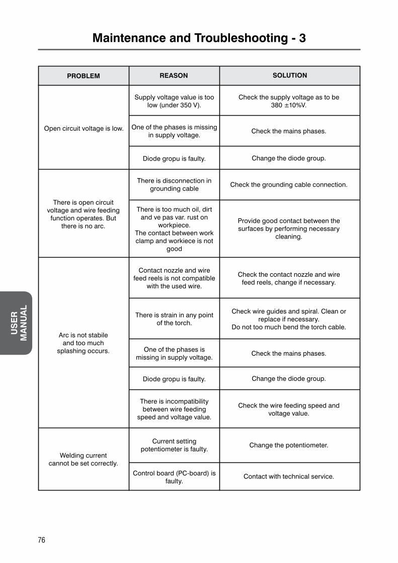
Diode gropu is faulty.
Diode gropu is faulty.
Control board (PC-board) is faulty.
There is too much oil, dirt and ve pas var. rust on
workpiece.The contact between work clamp and workiece is not
good
There is incompatibility between wire feeding
speed and voltage value.
There is disconnection in grounding cable
One of the phases is missing in supply voltage.
Current setting potentiometer is faulty.
Contact nozzle and wire feed reels is not compatible
with the used wire.
There is strain in any point of the torch.
There is open circuit voltage and wire feeding function operates. But
there is no arc.
Arc is not stabileand too much
splashing occurs.
Welding currentcannot be set correctly.
Supply voltage value is too low (under 350 V).
One of the phases is missing in supply voltage.
Open circuit voltage is low.
Change the diode group.
Change the diode group.
Contact with technical service.
Provide good contact between the surfaces by performing necessary
cleaning.
Check the wire feeding speed andvoltage value.
Check the grounding cable connection.
Check the mains phases.
Change the potentiometer.
Check the contact nozzle and wirefeed reels, change if necessary.
Check wire guides and spiral. Clean or replace if necessary.
Do not too much bend the torch cable.
Check the supply voltage as to be 380 ±10%V.
Check the mains phases.
PROBLEM REASON SOLUTION
US
ER
M
AN
UA
L
76

Maintenance and Troubleshooting - 4
Gas solenoid is faulty.
On/Off switch is faulty.
There is no supply voltage.
Power indicator lamp is faulty.
Thermal protection is activated.
Power indicator lamplights but contactor
doesn’t operate.
Power indicator lampdoesn’t light upon
machine start.
Gas hose is not connected or there is disconnection in
the hose.
Inlet guide is too away from the wire feed reels or
guides are blocked.
Inlet /outlet guides and wirefeed reels are not on the
same axis.
Gas hose is crushed or blocked.
End of the wire stucked tocontact nozzle.
Inner diameters of inlet/outlet guides are too wide
or too narrow.
There is no shieldinggas flow.
Wire is curled withintorch, bended infeed reels or inlet
guide.
Clean the electronic valve or replacewith the new one.
Change On/Off switch.
Check the mains voltage.
Change the power indicator lamp.
Leave the machine to cool down.
Check the hose and gas connectionsystem. Tighten the connections.
Replace the hose if necessary.
Check the distance. Performnecessary adjustments. Clean
the guides.
Perform the necessary changesto have them on the same axis.
Check the gas connection hose.
Change the contact nozzle and ifnecessary change the nozzle.
Change inlet/outlet guides.
PROBLEM REASON SOLUTION
US
ER
M
AN
UA
L
77
Failures in Welding Seams - 1
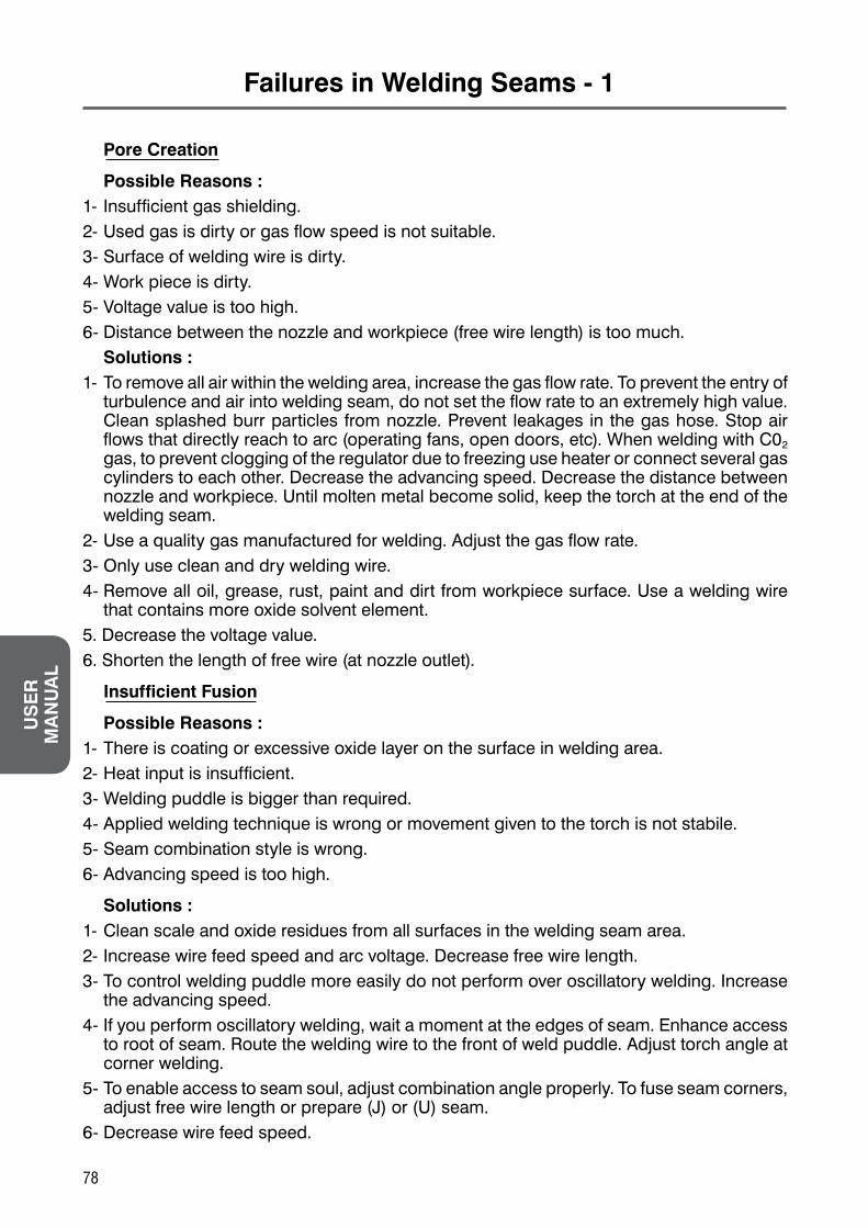
Pore Creation
Possible Reasons :1- Insufficient gas shielding.2- Used gas is dirty or gas flow speed is not suitable.3- Surface of welding wire is dirty.4- Work piece is dirty.5- Voltage value is too high.6- Distance between the nozzle and workpiece (free wire length) is too much. Solutions :1- To remove all air within the welding area, increase the gas flow rate. To prevent the entry of
turbulence and air into welding seam, do not set the flow rate to an extremely high value. Clean splashed burr particles from nozzle. Prevent leakages in the gas hose. Stop air flows that directly reach to arc (operating fans, open doors, etc). When welding with C02 gas, to prevent clogging of the regulator due to freezing use heater or connect several gas cylinders to each other. Decrease the advancing speed. Decrease the distance between nozzle and workpiece. Until molten metal become solid, keep the torch at the end of the welding seam.
2- Use a quality gas manufactured for welding. Adjust the gas flow rate.3- Only use clean and dry welding wire.4- Remove all oil, grease, rust, paint and dirt from workpiece surface. Use a welding wire
that contains more oxide solvent element.5. Decrease the voltage value.6. Shorten the length of free wire (at nozzle outlet).
Insufficient Fusion
Possible Reasons :1- There is coating or excessive oxide layer on the surface in welding area.2- Heat input is insufficient.3- Welding puddle is bigger than required.4- Applied welding technique is wrong or movement given to the torch is not stabile.5- Seam combination style is wrong.6- Advancing speed is too high.
Solutions :1- Clean scale and oxide residues from all surfaces in the welding seam area.2- Increase wire feed speed and arc voltage. Decrease free wire length.3- To control welding puddle more easily do not perform over oscillatory welding. Increase
the advancing speed.4- If you perform oscillatory welding, wait a moment at the edges of seam. Enhance access
to root of seam. Route the welding wire to the front of weld puddle. Adjust torch angle at corner welding.
5- To enable access to seam soul, adjust combination angle properly. To fuse seam corners, adjust free wire length or prepare (J) or (U) seam.
6- Decrease wire feed speed.
US
ER
M
AN
UA
L
78

Failures in Welding Seams - 2
Insufficient Penetration
Possible Reasons :1- Combination preparation is wrong.2- Applied welding technique is wrong.3- Heat input is insufficient.
Solutions :1- To access to the soul of seam, with the condition to provide correct free wire length and
arc characteristics, revise connection shape and connection preparation. Avoid that the height in the root is extremely high. In butt joint welding, increase root opening or deepen the groove opened reversely.
2- To achieve maximum penetration, hold the welding wire perpendicular to workpiece. Route the arc to the front of weld puddle.
3- Current may be too low according to voltage. Increase the wire feeding speed, so the current. Do not change the free wire length.
Root Sagging
Possible Reasons :1- Welding speed is too low.2- Current is too high when compared to the voltage. Solutions :1- Increase the advancing speed. Adjust the torch angle.2- Increase the arc voltage.
Splashing
Possible Reasons :1- Welding wire short circuits by contacting to work piece.2- CO2 is used as shielding gas.3- Welding process is performed with global conduction by using argon gas. Solutions.
Solutions :1- Increase the arc voltage. If you are operating with short circuit conduction, limit the current
increase by increasing the inductance in welding machine.2- Decrease the arc voltage or “immerse” the arc by increasing the wire feeding speed, so
limit the splashing.3- By increasing the current, enter into spray conduction mode.
Edge Burn
Possible Reasons :1- Advancing speed is too high.2- Welding voltage is too high.3- Welding current is too high.4- Waiting time is insufficient.5- Torch angle is wrong.
Solutions :1- Decrease the advancing speed.2- Decrease the voltage.3- Decrease wire feed speed.4- Wait more in the edges of molten weld puddle.5- By adjusting the torch angle, enable arc to route the molten metal.
US
ER
M
AN
UA
L
79

Electrical Circuit Diagram - 1
ASKAYNAKMasterMIG 350
A
K4K6 K5K2
K3
W1
W2
W3Solenoid Torch
SwitchGas Control
Switch
BurnbackTime
Slow Wire FeedWire Feed Speed
w/o welding
Current ControlSwitch
Wire Feeder Unit Circuit Connection Diagram
Wire Feeder Socket
Main Electrical Circuit Connection Diagram
Machine Control Circuit Connection Diagram
Alarm
Heater
Electronic Power Indicator
Pacco Swich Direction
RightSide
LeftSide
RightSide
LeftSide
UP
Down
UP
Down
UP
Down
UP
Down
Location 1 Layer 2 Layer 3 Layer 4 Layer 5 Layer 6 Layer
US
ER
M
AN
UA
L
80

Electrical Circuit Diagram - 2
ASKAYNAKMasterMIG 350
A
K4K6 K5K2
K3
W1
W2
W3Solenoid Torch
SwitchGas Control
Switch
BurnbackTime
Slow Wire FeedWire Feed Speed
w/o welding
Current ControlSwitch
Wire Feeder Unit Circuit Connection Diagram
Wire Feeder Socket
Main Electrical Circuit Connection Diagram
Machine Control Circuit Connection Diagram
Alarm
Heater
Electronic Power Indicator
Pacco Swich Direction
RightSide
LeftSide
RightSide
LeftSide
UP
Down
UP
Down
UP
Down
UP
Down
Location 1 Layer 2 Layer 3 Layer 4 Layer 5 Layer 6 Layer
US
ER
M
AN
UA
L
81

Spare Parts - 1
Power Unit
No. SupplierPart Number
AskaynakPart Number Description Qty
123456789101112131415161718192021
1.1.01.01.03422.07.25.9502.07.41.0042.05.07.108
1.1.01.05.01412.07.89.048
1.1.01.03.10682.07.52.0192.07.52.0282.07.57.757
1.1.01.05.01442.07.57.960
1.2.07.01.01241.1.01.04.0379
2.04.30.1042.07.54.1222.07.52.0202.01.29.0062.05.01.0182.05.01.021
1.1.02.01.1023
821101010342822072595082207410048220507108
8211010501418220789048
821101031068822075201982207520288220757757
8211010501448220757960
821207010124821101040379822043010482207541228220752020822012900682205010188220501021
821102011023
Top coverControl transformerContactorRear wheel 250x50Cylinder Bracket Support (left)Fan (MM350)Rear panel MM350Fuse 8 AFuse holderHeater connector (Female) XS16K2ACable hookWelding socket femaleInput supply cableGas cylinder supportCable glandControl cable socketFuse 3 ASchackleRadiator insulation sleeve -1 Radiator insulation sleeve -2Fan support -1
111211112111111111442
US
ER
M
AN
UA
L
82

Spare Parts - 2
No. SupplierPart Number
AskaynakPart Number
Description Qty
22232425262728293031323334353637383940414243444546474849505152535455565758
1.1.01.04.03772.06.14.404
1.1.01.05.01421.1.01.05.01401.1.02.01.09671.1.01.02.86421.1.04.03.01051.1.01.04.0376
2.05.07.3032.07.80.5662.07.80.569
1.1.01.03.10691.2.08.02.0171
2.07.80.2132.07.28.2112.07.28.2092.07.46.754
1.1.01.05.01382.01.31.0612.01.31.062
1.1.02.01.09572.07.37.5512.07.42.009
1.1.04.01.16541.1.01.04.03781.1.05.04.0010
2.07.91.0071.1.05.02.02941.1.01.02.8641
2.06.04.0101.2.07.03.04341.2.07.03.04371.2.07.03.04351.2.07.03.03981.2.07.03.04081.2.07.03.04101.2.07.03.0436
8211010403778220614404
821101050142821101050140821102010967821101028642821104030105821101040376822050730382207805668220780569
8211010310698212080201718220780213822072821182207282098220746754
82110105013882201310618220131062
82110201095782207375518220742009
8211040116548211010403788211050400108220791007
8211050202948211010286418220604010
821207030434821207030437821207030435821207030398821207030408821207030410821207030436
Fan mounting plateRear wheel nutCylinder support - RightAxle Axle mounting plate Right panelOutput inductance Bottom panelFront wheelFine adjustment switch 10 stepsCoarse adjustment switch 3 stepsFront PanelEarth cableOn/Off SwitchLed yellowLed greenDigital displayHandleHandle holder leftHandle holder rightRectifier bridge support3 phase rectifierShunt 400A-75mVMain transformer assemblyMiddle panelDigital display pc boardPlastic insulator Filter capacitor boardLeft panelLifting boltConnection cable - 1Connection cable - 2Connection cable - 3Connection cable - 4Connection cable - 5Connection cable - 6Connection cable - 7
1211211121111111211121111121121111111
US
ER
M
AN
UA
L
83

Spare Parts - 1
Wire Feeder Unit
No. SupplierPart Number
AskaynakPart Number Description Qty
1234567891011121213141516171819
11111111114111751122
2.05.05.3011.1.01.04.01892.05.05.095
1.1.01.03.11721.1.03.03.0090
2.02.20.4202.07.55.0062.07.54.1042.07.57.117
1.1.04.07.00012.07.57.822
1.2.08.01.01651.2.08.01.01991.2.08.05.0053
2.08.02.2002.20.12.9952.20.02.213
1.2.02.01.32302.05.07.3142.08.02.201
82205053018211010401898220505095
8211010311728211030300908220220420822075500682207541048220757117
8211040700018220757822
821208010165821208010199821208050053822080220082220129958222002213
82120201323082205073148220802201
Spool Cover MF-3Middle panelWire axisRear panelCarrying handleGas connectorSolenoid valve MF-3Control cable connectorWelding socket maleMagnetic inductanceWater quick couplingConnection cable-1Connection cable-2Connection cable 5mConnection cable tubeHose clampsGas socket (Male)Right side panel (Fixed)Rear wheels MF-3Water hose Ø 10
US
ER
M
AN
UA
L
84

Spare Parts - 2
Warning Label
Please read the “Safety in Welding” section in pages 48-56 for detailed information.
No. SupplierPart Number
AskaynakPart Number
Description Qty
2021222324252627282930303132333435363737383940414243
11213112111111121211112222
1.1.01.04.01831.1.03.03.0093
2.05.07.3141.1.01.04.0435
2.07.10.0432.07.11.009
1.1.01.03.11732.07.80.841
1.2.07.03.03152.05.05.0812.20.08.7162.20.08.7182.07.80.3712.04.31.109
1.1.05.02.04962.05.06.0112.07.51.7032.05.06.0122.07.40.6632.07.40.6682.07.57.140
1.2.01.01.32792.05.05.902
1.1.03.03.00871.1.03.03.0088
2.07.11.006
821101040183821103030093
822050731482110104043582207100438220711009
8211010311738220780841
82120703031582205050818222008716822200871882207803718220431109
821105020496822050601182207517038220506012822074066382207406688220757140
8212010132798220505902
821103030087821103030088
8220711006
Wire feeder supportWire feeder carrying shaftFront wheels MF-3Bottom panelWire feed speed potentiometerWire feed speed potentiometer knobFront panel MF-3Wire feed buttonInner connection cableEuro connector insulation flangeAir cool torch MB36 4mWater cool torch MB501D 4m2/4 trigger selection switchCable insulation hoop Ø 35Wire feed control board MF-3 (NEW)Wire feed insulation piece-1MagnetWire feed insulation piece-2Wire drive motorWire drive motorEuro connector (Inner piece)Left side panel (Hinged)Top panel hinge-1Top panel hinge-2Top panel hinge-3Potentiometer knob
US
ER
M
AN
UA
L
85

US
ER
M
AN
UA
L
86
Wire Feeder and Power Unit Specifications
Wire Feeder Unit
Power Unit