garlock expansion joints · industry and as a result maintains a 10cfr50 appendix b (safety...
TRANSCRIPT
Leaders in Sealing Integrity
Garlock Expansion JointsTechnical Manual
PROUDLY MADE IN
A M E R I C A
1887SI NC E

Garlock Fluid Sealing Products Technical Manual
Leaders in Sealing Integrity
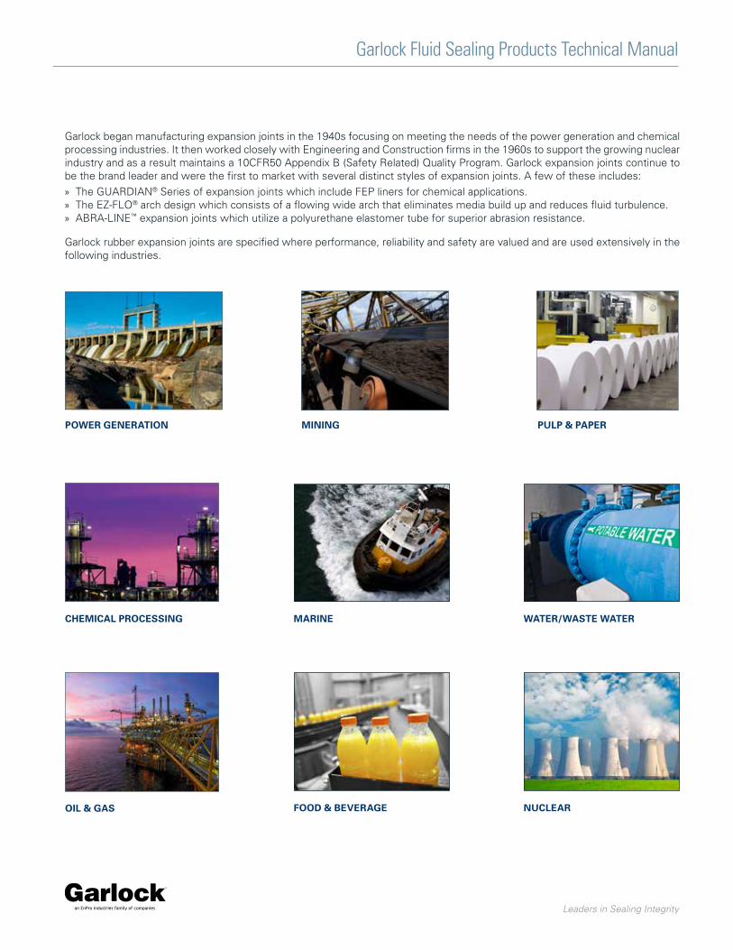
Garlock began manufacturing expansion joints in the 1940s focusing on meeting the needs of the power generation and chemical processing industries. It then worked closely with Engineering and Construction firms in the 1960s to support the growing nuclear industry and as a result maintains a 10CFR50 Appendix B (Safety Related) Quality Program. Garlock expansion joints continue to be the brand leader and were the first to market with several distinct styles of expansion joints. A few of these includes:
» The GUARDIAN® Series of expansion joints which include FEP liners for chemical applications. » The EZ-FLO® arch design which consists of a flowing wide arch that eliminates media build up and reduces fluid turbulence. » ABRA-LINE™ expansion joints which utilize a polyurethane elastomer tube for superior abrasion resistance.
Garlock rubber expansion joints are specified where performance, reliability and safety are valued and are used extensively in the following industries.
POWER GENERATION MINING
CHEMICAL PROCESSING
OIL & GAS
MARINE
FOOD & BEVERAGE
PULP & PAPER
WATER/WASTE WATER
NUCLEAR
CONTENTS
Full Vacuum ApplicationsStyles 204, 204HP, 204EPS ......................................................6Style 204EVS/204 MAX ............................................................7
General ServiceStyle 206 EZ-FLO® ....................................................................8GARFLEX® 8100 .......................................................................9
Abrasive ApplicationsABRA-LINE™ Style 404, 404HP, 404EPS ................................10ABRA-LINE™ Style 406 EZ-FLO®.............................................11ABRA-LINE™ Style 4394 .........................................................12
Chemical ApplicationsGUARDIAN® 200 & 200HP .....................................................13GUARDIAN® 306 EZ-FLO® ......................................................14Styles 214, 215 & 216 ............................................................15
Low Pressure ApplicationsStyle 9394 ...............................................................................17Style 8400 Flue Ducts ............................................................18
Specialty DesignsStyle 7250 FLEXO-MATIC® .....................................................19Style 207 & 208 ......................................................................20Style 8420 Split .......................................................................21
Industry Specific ...................................................................22
Technical Data .......................................................................23
Garlock expansion joints offer superior performance, reliability and service life. This in turn improves plant safety, increases the mechanical integrity of equipment and allows customers to gain a competitive advantage in the market place.
Types of Expansion Joints ............................................... 26
Expansion Joint Components/Accessories ................... 27
Types of Pipe Movement ................................................. 28
Typical Properties of Elastomers .................................... 29
Installation ........................................................................ 30
Troubleshooting ............................................................... 31
General Precautions ......................................................... 31
Expansion Joint Weights ................................................. 32
Application Data Form ..................................................... 33
Spring Rates/Effective Area ............................................ 38
Survey Data Form ............................................................. 39
Garlock Fluid Sealing Products Technical Manual
Leaders in Sealing Integrity

Introduction
An expansion joint is a specially engineered product inserted in a rigid piping system to achieve one or more of the following:
» Absorb movement » Relieve system strain due to thermal change, load stress,
pumping surges, wear or settling » Reduce mechanical noise » Compensate for misalignment » Eliminate electrolysis between dissimilar metals
At Garlock, the range of our engineering emphasis extends from the selection of the fabric used for reinforcement to the choice of materials used in actual expansion joint construction.
Rigid laboratory and field tests of Garlock expansion joints are what back up our assurances of long life and reliable service. An important word on safety: all Garlock expansion joints carry safety ratings exceeding product specifications in such areas as pressure and movement.
Garlock nonmetallic expansion joints and flexible couplings are ideally suited for hundreds of applications in a wide range of industries, including:
» Power generating » Pulp and paper » Chemical » Waste water and sewage disposal » Marine » Heating, ventilating and air conditioning » Food & Beverage » Oil & Gas and Petrochemical » Mining
Joint Selection
To select the proper expansion joint, consider:
» Pipe size » Pumped medium: type of liquid, gas, or vapor in system » Temperature range » Pressure/vacuum range » Movements needed » Environment: degree of exposure to:
› Weathering › Oil › Sunlight › Open flame › Liquids › Chemicals › Gases › Other › Vapors » Installed face-to-face dimensions » Degree of pipe misalignment » Drilling: if other than standard 125Ib. ANSI, determine:
› Flange O.D. › Bolt circle › Number of bolt holes › Diameter of hole » Need for retaining rings » Need for control units
› Recommended for use with most expansion joints › Must be used in cases of insufficient pipe support » Need for special construction
GARLOCK RECOMMENDATIONS
200 200HP 204/204HP 206 207/
208214/215 306 8100 9394 8400 406 404 404HP 404EPS 4394
Abrasive Applications • • • • •
Full Vacuum/Suction Applications • • • • • • •
Low Pressure • • •
Marine • • •
Chemical • • • •
Nuclear • •
Garlock Fluid Sealing Products Technical Manual
Leaders in Sealing Integrity
Garlock Fluid Sealing Products Technical Manual
Leaders in Sealing Integrity
6
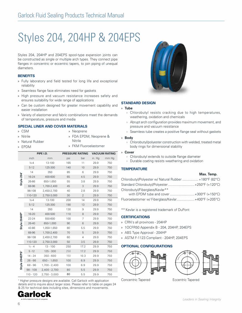
Styles 204, 204HP & 204EPSStyles 204, 204HP and 204EPS spool-type expansion joints can be constructed as single or multiple arch types. They connect pipe flanges in concentric or eccentric tapers, to join piping of unequal diameters.
BENEFITS » Fully laboratory and field tested for long life and exceptional
reliability
» Seamless flange face eliminates need for gaskets
» High pressure and vacuum resistance increases safety and ensures suitability for wide range of applications
» Can be custom designed for greater movement capability and easier installation
» Variety of elastomer and fabric combinations meet the demands of temperature, pressure and media
TEMPERATURE Max. Temp. Chlorobutyl/Polyester w/ Natural Rubber ................. +180°F (82°C)
Standard Chlorobutyl/Polyester ............................+250°F (+120°C)
Chlorobutyl/Fiberglass/Kevlar** with EPDM tube and cover ..........................+300°F (+150°C)
Fluoroelastomer w/ Fiberglass/Kevlar ...................+400°F (+205°C)
** Kevlar is a registered trademark of DuPont
SPECIAL LINER AND COVER MATERIALS » CSM
» Nitrile
» Natural Rubber
» EPDM
» Neoprene
» FDA EPDM, Neoprene & Nitrile
» FKM Fluoroelastomer
OPTIONAL CONFIGURATIONS
PIPE I.D. PRESSURE RATING VACUUM RATING
inch mm psi bar in. Hg mm Hg
Sty
le 2
04†
½-4 13-100 165 11 29.9 750
5-12 125-300 140 10 29.9 750
14 350 85 6 29.9 750
16-24 400-600 65 4.5 29.9 750
26-66 650-1,650 55 3.8 29.9 750
68-96 1,700-2,400 45 3 29.9 750
98-108 2,450-2,700 40 2.8 29.9 750
110-120 2,750-3,000 30 2 29.9 750
Sty
le 2
04H
P†
½-4 13-100 200 14 29.9 750
5-12 125-300 190 13 29.9 750
14 350 130 9 29.9 750
16-20 400-500 110 8 29.9 750
22-24 550-600 100 7 29.9 750
26-40 650-1,000 90 6 29.9 750
42-66 1,050-1,650 80 5.5 29.9 750
68-96 1,700-2,400 70 5 29.9 750
98-108 2,450-2,700 60 4 29.9 750
110-120 2,750-3,000 50 3.5 29.9 750
Sty
le 2
04E
PS
†
½ - 4 13 - 100 250 17.2 29.9 750
5 -12 125 - 300 250 17.2 29.9 750
14 - 24 350 - 600 150 10.3 29.9 750
26 - 66 650 - 1,650 100 6.9 29.9 750
68 - 96 1,700 - 2,400 100 6.9 29.9 750
98 - 108 2,400 - 2,700 80 5.5 29.9 750
110 - 120 2,750 - 3,000 80 5.5 29.9 750
STANDARD DESIGN » Tube
› Chlorobutyl resists cracking due to high temperatures, weathering, oxidation and chemicals
› Abrupt arch configuration provides maximum movement, and pressure and vacuum resistance
› Seamless tube creates a positive flange seal without gaskets
» Body › Chlorobutyl/polyester construction with welded, treated metal
body rings for dimensional stability
» Cover › Chlorobutyl extends to outside flange diameter › Durable coating resists weathering and oxidation
Concentric Tapered Eccentric Tapered† Higher pressure designs are available. Call Garlock with application details and to inquire about larger sizes. Please refer to table on pages 24 & 25 for technical data including sites, dimensions and movements.
CERTIFICATIONS » CRN's all provinces - 204HP
» 1OCFR50 Appendix B - 204, 204HP, 204EPS
» ABS Type Approval - 204HP
» ASTM F-1123 Compliant - 204HP, 204EPS
Garlock Fluid Sealing Products Technical Manual
Leaders in Sealing Integrity
7
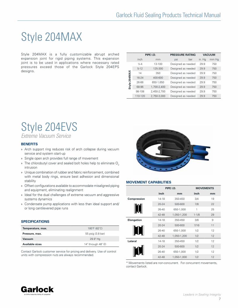
Style 204EVSExtreme Vacuum Service
Style 204MAX
BENEFITS » Arch support ring reduces risk of arch collapse during vacuum
service and system start-up » Single open arch provides full range of movement » The chlorobutyl cover and sealed bolt holes help to eliminate O2
intrusion » Unique combination of rubber and fabric reinforcement, combined
with metal body rings, ensure best adhesion and dimensional stability
» Offset configurations available to accommodate misaligned piping and equipment, eliminating realignment
» Ideal for the dual challenges of extreme vacuum and aggressive systems dynamics
» Condensate pump applications with less than ideal support and/or long cantilevered pipe runs
SPECIFICATIONS
Temperature, max. 180˚F (82˚C)
Pressure, max. 55 psig (3.8 bar)
Vacuum 29.9" Hg
Available sizes 14" through 48" ID
Contact Garlock customer service for pricing and delivery. Use of control units with compression nuts are always recommended.
MOVEMENT CAPABILITIES
PIPE I.D. MOVEMENTS
inch mm inch mm
Compression 14-18 350-450 3/4 19
20-24 500-600 7/8 22
26-40 650-1,000 1 25
42-48 1,050-1,200 1-1/8 29
Elongation 14-18 350-450 3/8 9
20-24 500-600 7/16 11
26-40 650-1,000 1/2 12
42-48 1,050-1,200 1/2 12
Lateral 14-18 350-450 1/2 12
20-24 500-600 1/2 12
26-40 650-1,000 1/2 12
42-48 1,050-1,000 1/2 12
* Movements listed are non-concurrent. For concurrent movements, contact Garlock.
Style 204MAX is a fully customizable abrupt arched expansion joint for rigid piping systems. This expansion joint is to be used in applications where necessary rated pressures exceed those of the Garlock Style 204EPS designs.
PIPE I.D. PRESSURE RATING VACUUM
inch mm psi bar in. Hg mm Hg
Sty
le 2
04M
AX
½-4 13-100 Designed as needed 29.9 750
5-12 125-300 Designed as needed 29.9 750
14 350 Designed as needed 29.9 750
16-24 400-600 Designed as needed 29.9 750
26-66 650-1,650 Designed as needed 29.9 750
68-96 1,700-2,400 Designed as needed 29.9 750
98-108 2,450-2,700 Designed as needed 29.9 750
110-120 2,750-3,000 Designed as needed 29.9 750
Garlock Fluid Sealing Products Technical Manual
Leaders in Sealing Integrity
8
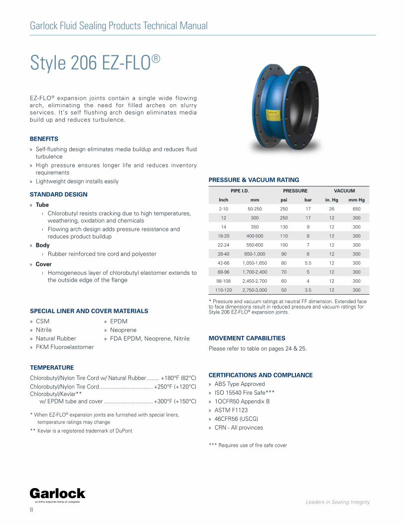
Style 206 EZ-FLO®
EZ-FLO® expansion joints contain a single wide flowing arch, eliminating the need for filled arches on slurry services. It’s self flushing arch design eliminates media build up and reduces turbulence.
BENEFITS
» Self-flushing design eliminates media buildup and reduces fluid turbulence
» High pressure ensures longer life and reduces inventory requirements
» Lightweight design installs easily
STANDARD DESIGN
» Tube › Chlorobutyl resists cracking due to high temperatures,
weathering, oxidation and chemicals
› Flowing arch design adds pressure resistance and reduces product buildup
» Body › Rubber reinforced tire cord and polyester
» Cover › Homogeneous layer of chlorobutyl elastomer extends to
the outside edge of the flange
TEMPERATURE
Chlorobutyl/Nylon Tire Cord w/ Natural Rubber ........ +180°F (82°C)
Chlorobutyl/Nylon Tire Cord .................................. +250°F (+120°C)Chlorobutyl/Kevlar** w/ EPDM tube and cover ............................... +300°F (+150°C)
* When EZ-FLO® expansion joints are furnished with special liners, temperature ratings may change
** Kevlar is a registered trademark of DuPont
PRESSURE & VACUUM RATING
PIPE I.D. PRESSURE VACUUM
Inch mm psi bar in. Hg mm Hg
2-10 50-250 250 17 26 650
12 300 250 17 12 300
14 350 130 9 12 300
16-20 400-500 110 8 12 300
22-24 550-600 100 7 12 300
26-40 650-1,000 90 6 12 300
42-66 1,050-1,650 80 5.5 12 300
68-96 1,700-2,400 70 5 12 300
98-108 2,450-2,700 60 4 12 300
110-120 2,750-3,000 50 3.5 12 300
* Pressure and vacuum ratings at neutral FF dimension. Extended face to face dimensions result in reduced pressure and vacuum ratings for Style 206 EZ-FLO® expansion joints.
MOVEMENT CAPABILITIES
Please refer to table on pages 24 & 25.
SPECIAL LINER AND COVER MATERIALS
» CSM
» Nitrile
» Natural Rubber
» FKM Fluoroelastomer
» EPDM
» Neoprene
» FDA EPDM, Neoprene, Nitrile
CERTIFICATIONS AND COMPLIANCE » ABS Type Approved
» ISO 15540 Fire Safe***
» 1OCFR50 Appendix B
» ASTM F1123
» 46CFR56 (USCG)
» CRN - All provinces
*** Requires use of fire safe cover
Garlock Fluid Sealing Products Technical Manual
Leaders in Sealing Integrity
9
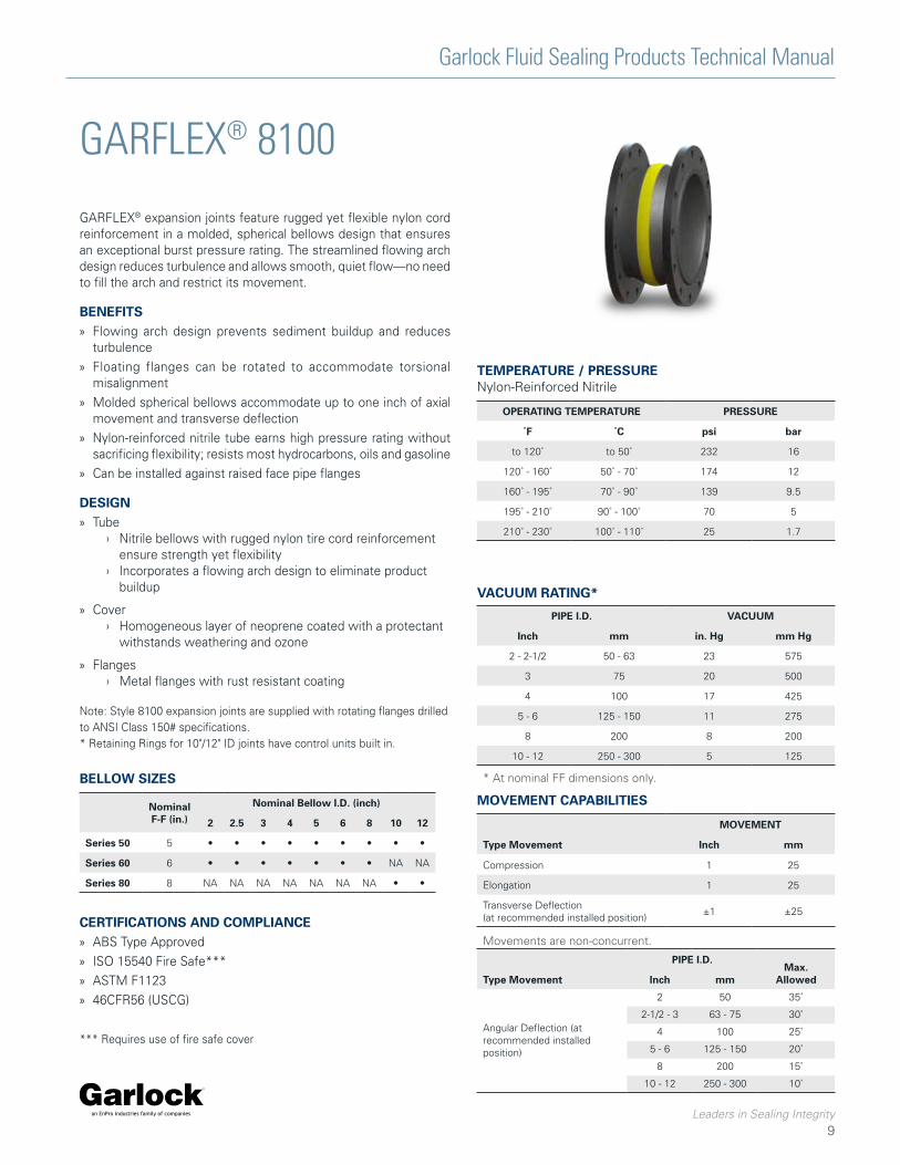
GARFLEX® 8100
GARFLEX® expansion joints feature rugged yet flexible nylon cord reinforcement in a molded, spherical bellows design that ensures an exceptional burst pressure rating. The streamlined flowing arch design reduces turbulence and allows smooth, quiet flow—no need to fill the arch and restrict its movement.
BENEFITS » Flowing arch design prevents sediment buildup and reduces
turbulence
» Floating flanges can be rotated to accommodate torsional misalignment
» Molded spherical bellows accommodate up to one inch of axial movement and transverse deflection
» Nylon-reinforced nitrile tube earns high pressure rating without sacrificing flexibility; resists most hydrocarbons, oils and gasoline
» Can be installed against raised face pipe flanges
DESIGN » Tube
› Nitrile bellows with rugged nylon tire cord reinforcement ensure strength yet flexibility
› Incorporates a flowing arch design to eliminate product buildup
» Cover › Homogeneous layer of neoprene coated with a protectant
withstands weathering and ozone
» Flanges › Metal flanges with rust resistant coating
Note: Style 8100 expansion joints are supplied with rotating flanges drilled to ANSI Class 150# specifications.* Retaining Rings for 10"/12" ID joints have control units built in.
OPERATING TEMPERATURE PRESSURE
˚F ˚C psi bar
to 120˚ to 50˚ 232 16
120˚ - 160˚ 50˚ - 70˚ 174 12
160˚ - 195˚ 70˚ - 90˚ 139 9.5
195˚ - 210˚ 90˚ - 100˚ 70 5
210˚ - 230˚ 100˚ - 110˚ 25 1.7
TEMPERATURE / PRESSURENylon-Reinforced Nitrile
PIPE I.D. VACUUM
Inch mm in. Hg mm Hg
2 - 2-1/2 50 - 63 23 575
3 75 20 500
4 100 17 425
5 - 6 125 - 150 11 275
8 200 8 200
10 - 12 250 - 300 5 125
VACUUM RATING*
MOVEMENT
Type Movement Inch mm
Compression 1 25
Elongation 1 25
Transverse Deflection (at recommended installed position)
±1 ±25
MOVEMENT CAPABILITIES
Movements are non-concurrent.
* At nominal FF dimensions only.
Type Movement
PIPE I.D.Max.
AllowedInch mm
Angular Deflection (at recommended installed position)
2 50 35˚
2-1/2 - 3 63 - 75 30˚
4 100 25˚
5 - 6 125 - 150 20˚
8 200 15˚
10 - 12 250 - 300 10˚
Nominal F-F (in.)
Nominal Bellow I.D. (inch)
2 2.5 3 4 5 6 8 10 12
Series 50 5 • • • • • • • • •
Series 60 6 • • • • • • • NA NA
Series 80 8 NA NA NA NA NA NA NA • •
BELLOW SIZES
CERTIFICATIONS AND COMPLIANCE » ABS Type Approved
» ISO 15540 Fire Safe***
» ASTM F1123
» 46CFR56 (USCG)
*** Requires use of fire safe cover
Garlock Fluid Sealing Products Technical Manual
Leaders in Sealing Integrity
10
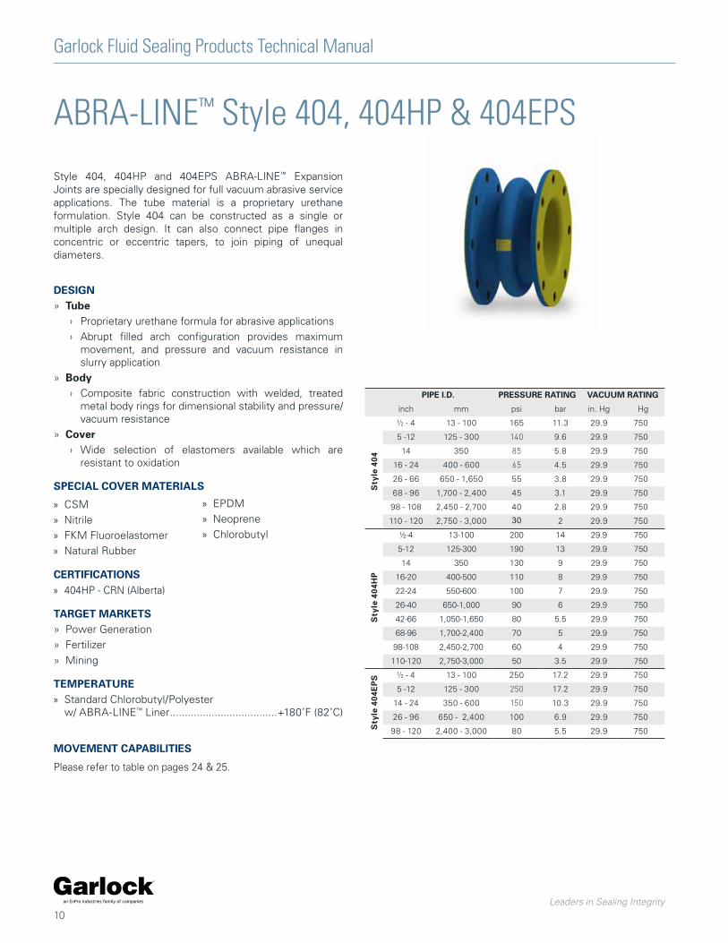
ABRA-LINE™ Style 404, 404HP & 404EPS
Style 404, 404HP and 404EPS ABRA-LINE™ Expansion Joints are specially designed for full vacuum abrasive service applications. The tube material is a proprietary urethane formulation. Style 404 can be constructed as a single or multiple arch design. It can also connect pipe flanges in concentric or eccentric tapers, to join piping of unequal diameters.
DESIGN» Tube
› Proprietary urethane formula for abrasive applications
› Abrupt filled arch configuration provides maximum movement, and pressure and vacuum resistance in slurry application
» Body › Composite fabric construction with welded, treated
metal body rings for dimensional stability and pressure/vacuum resistance
» Cover › Wide selection of elastomers available which are
resistant to oxidation
SPECIAL COVER MATERIALS
» CSM
» Nitrile
» FKM Fluoroelastomer
» Natural Rubber
CERTIFICATIONS » 404HP - CRN (Alberta)
TARGET MARKETS» Power Generation
» Fertilizer
» Mining
TEMPERATURE » Standard Chlorobutyl/Polyester
w/ ABRA-LINE™ Liner ....................................+180˚F (82˚C)
» EPDM
» Neoprene
» Chlorobutyl
PIPE I.D. PRESSURE RATING VACUUM RATING
inch mm psi bar in. Hg Hg
Sty
le 4
04
½ - 4 13 - 100 165 11.3 29.9 750
5 -12 125 - 300 140 9.6 29.9 750
14 350 85 5.8 29.9 750
16 - 24 400 - 600 65 4.5 29.9 750
26 - 66 650 - 1,650 55 3.8 29.9 750
68 - 96 1,700 - 2,400 45 3.1 29.9 750
98 - 108 2,450 - 2,700 40 2.8 29.9 750
110 - 120 2,750 - 3,000 30 2 29.9 750
Sty
le 4
04H
P
½-4 13-100 200 14 29.9 750
5-12 125-300 190 13 29.9 750
14 350 130 9 29.9 750
16-20 400-500 110 8 29.9 750
22-24 550-600 100 7 29.9 750
26-40 650-1,000 90 6 29.9 750
42-66 1,050-1,650 80 5.5 29.9 750
68-96 1,700-2,400 70 5 29.9 750
98-108 2,450-2,700 60 4 29.9 750
110-120 2,750-3,000 50 3.5 29.9 750
Sty
le 4
04E
PS ½ - 4 13 - 100 250 17.2 29.9 750
5 -12 125 - 300 250 17.2 29.9 750
14 - 24 350 - 600 150 10.3 29.9 750
26 - 96 650 - 2,400 100 6.9 29.9 750
98 - 120 2,400 - 3,000 80 5.5 29.9 750
MOVEMENT CAPABILITIES
Please refer to table on pages 24 & 25.
Garlock Fluid Sealing Products Technical Manual
Leaders in Sealing Integrity
11
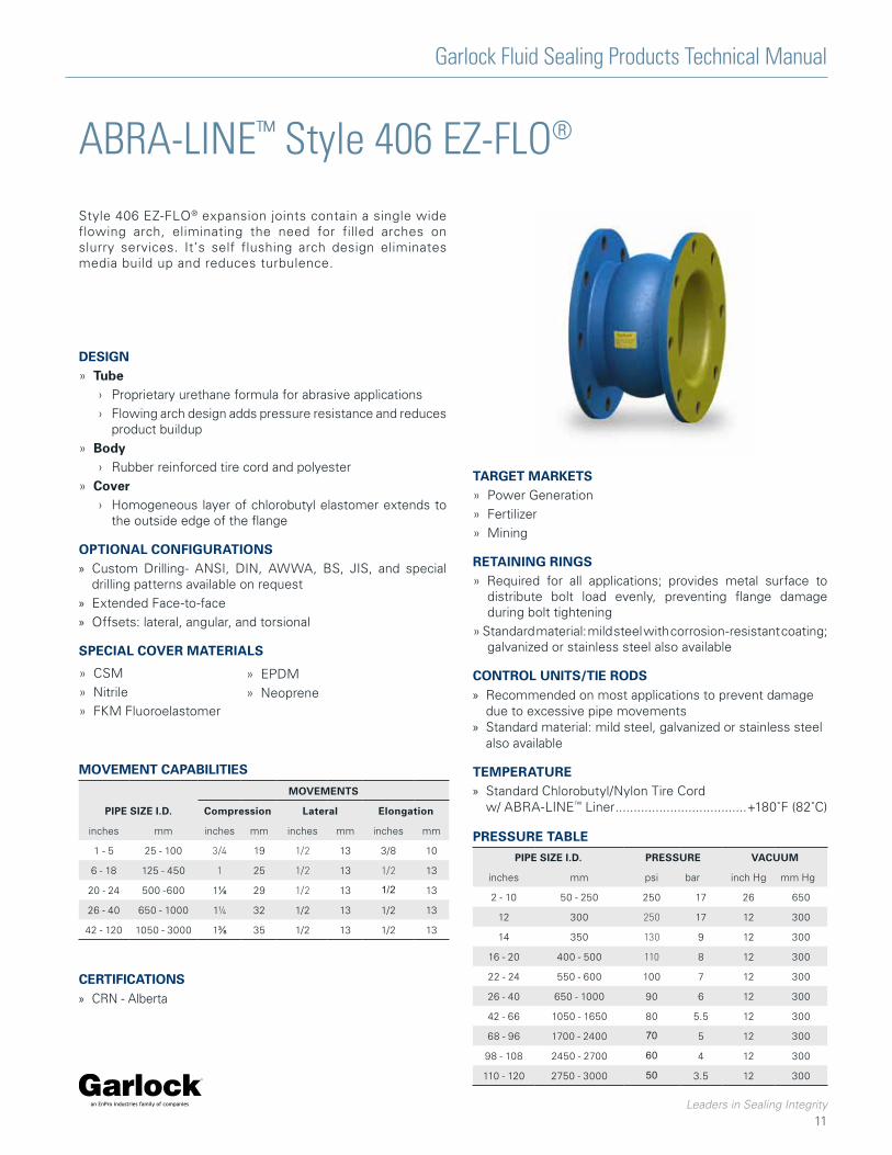
ABRA-LINE™ Style 406 EZ-FLO®
Style 406 EZ-FLO® expansion joints contain a single wide flowing arch, eliminating the need for filled arches on slurry services. It’s self flushing arch design eliminates media build up and reduces turbulence.
TARGET MARKETS» Power Generation
» Fertilizer
» Mining
RETAINING RINGS» Required for all applications; provides metal surface to distribute bolt load evenly, preventing flange damage during bolt tightening
» Standard material: mild steel with corrosion-resistant coating; galvanized or stainless steel also available
CONTROL UNITS/TIE RODS » Recommended on most applications to prevent damage
due to excessive pipe movements » Standard material: mild steel, galvanized or stainless steel
also available
TEMPERATURE » Standard Chlorobutyl/Nylon Tire Cord
w/ ABRA-LINE™ Liner ....................................+180˚F (82˚C)
DESIGN» Tube
› Proprietary urethane formula for abrasive applications
› Flowing arch design adds pressure resistance and reduces product buildup
» Body › Rubber reinforced tire cord and polyester
» Cover › Homogeneous layer of chlorobutyl elastomer extends to
the outside edge of the flange
OPTIONAL CONFIGURATIONS » Custom Drilling- ANSI, DIN, AWWA, BS, JIS, and special
drilling patterns available on request
» Extended Face-to-face
» Offsets: lateral, angular, and torsional
SPECIAL COVER MATERIALS
» CSM
» Nitrile
» FKM Fluoroelastomer
» EPDM
» Neoprene
PRESSURE TABLE
MOVEMENT CAPABILITIES
PIPE SIZE I.D.
MOVEMENTS
Compression Lateral Elongation
inches mm inches mm inches mm inches mm
1 - 5 25 - 100 3/4 19 1/2 13 3/8 10
6 - 18 125 - 450 1 25 1/2 13 1/2 13
20 - 24 500 -600 1⅛ 29 1/2 13 1/2 13
26 - 40 650 - 1000 1¼ 32 1/2 13 1/2 13
42 - 120 1050 - 3000 1⅜ 35 1/2 13 1/2 13
PIPE SIZE I.D. PRESSURE VACUUM
inches mm psi bar inch Hg mm Hg
2 - 10 50 - 250 250 17 26 650
12 300 250 17 12 300
14 350 130 9 12 300
16 - 20 400 - 500 110 8 12 300
22 - 24 550 - 600 100 7 12 300
26 - 40 650 - 1000 90 6 12 300
42 - 66 1050 - 1650 80 5.5 12 300
68 - 96 1700 - 2400 70 5 12 300
98 - 108 2450 - 2700 60 4 12 300
110 - 120 2750 - 3000 50 3.5 12 300
CERTIFICATIONS » CRN - Alberta
Garlock Fluid Sealing Products Technical Manual
Leaders in Sealing Integrity
12
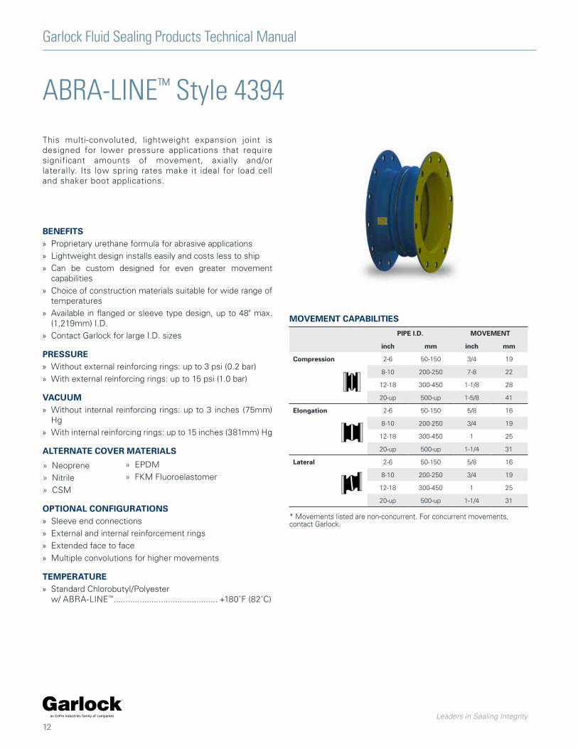
ABRA-LINE™ Style 4394
This multi-convoluted, lightweight expansion joint is designed for lower pressure applications that require significant amounts of movement, axially and/or laterally. Its low spring rates make it ideal for load cell and shaker boot applications.
BENEFITS » Proprietary urethane formula for abrasive applications
» Lightweight design installs easily and costs less to ship
» Can be custom designed for even greater movement capabilities
» Choice of construction materials suitable for wide range of temperatures
» Available in flanged or sleeve type design, up to 48" max. (1,219mm) I.D.
» Contact Garlock for large I.D. sizes
PRESSURE » Without external reinforcing rings: up to 3 psi (0.2 bar)
» With external reinforcing rings: up to 15 psi (1.0 bar)
VACUUM » Without internal reinforcing rings: up to 3 inches (75mm)
Hg
» With internal reinforcing rings: up to 15 inches (381mm) Hg
ALTERNATE COVER MATERIALS
» Neoprene
» Nitrile
» CSM
OPTIONAL CONFIGURATIONS » Sleeve end connections
» External and internal reinforcement rings
» Extended face to face
» Multiple convolutions for higher movements
TEMPERATURE » Standard Chlorobutyl/Polyester
w/ ABRA-LINE™ ............................................ +180˚F (82˚C)
» EPDM
» FKM Fluoroelastomer
MOVEMENT CAPABILITIES
PIPE I.D. MOVEMENT
inch mm inch mm
Compression 2-6 50-150 3/4 19
8-10 200-250 7-8 22
12-18 300-450 1-1/8 28
20-up 500-up 1-5/8 41
Elongation 2-6 50-150 5/8 16
8-10 200-250 3/4 19
12-18 300-450 1 25
20-up 500-up 1-1/4 31
Lateral 2-6 50-150 5/8 16
8-10 200-250 3/4 19
12-18 300-450 1 25
20-up 500-up 1-1/4 31
* Movements listed are non-concurrent. For concurrent movements, contact Garlock.

Garlock Fluid Sealing Products Technical Manual
Leaders in Sealing Integrity
13
GUARDIAN® 200 and 200HP
Garlock GUARDIAN® 200 expansion joints consist of a chemically-resistant FEP* liner mechanically bonded to an abrupt arch. A chlorobutyl cover and blue protective coating add resistance to environmental effects. (Alternate cover materials available.)
BENEFITS » High-density FEP liner reduces permeation and offers optimal
chemical resistance
» Mechanically bound liner reduces delamination; no glue to be vulnerable to chemical attack
» High pressure and vacuum resistance ensures suitability for broad range of applications
» Available with GYLON® 3545 gasket face for raised face flange connections. A gasket is not required on FF flange. FEP is compressible to achieve seal.
DESIGN » Tube
› Seamless FEP lining extends to the outer edge of the flange; completely fused to the joint body
› Abrupt arch design used for maximum movement capabilities
» Body › Chlorobutyl/Polyester construction with welded, treated metal
body rings for dimensional stability
» Cover › Homogeneous layer of chlorobutyl elastomer is standard
› Elastomer extends to the outside diameter of the flange
TEMPERATURE Max. Temp. Standard Chlorobutyl/Polyester ........................ +250°F (+120°C)
Chlorobutyl/Fiberglass/Kevlar** with EPDM cover ..................................... +300°F (+150°C)
Fluoroelastomer w/ Fiberglass/Kevlar** ........... +400°F (+205°C)
* Fluorinated Ethylene Propylene
** Kevlar is a registered trademark of DuPont.
PRESSURE & VACUUM RATING
PIPE I.D. PRESSURE VACUUM
Inch mm psi bar in. Hg mm Hg
GU
AR
DIA
N® 2
00† 2-4 50-100 165 11 29.9 750
5-12 125-300 140 10 29.9 750
14 350 85 6 29.9 750
16-24 400-600 65 5 29.9 750
26-30 650-750 55 4 29.9 750
GU
AR
DIA
N® 2
00H
P† 2-4 50-100 200 14 29.9 750
5-12 125-300 190 13 29.9 750
14 350 130 9 29.9 750
16-20 400-500 110 8 29.9 750
22-24 550-600 100 7 29.9 750
26-30 650-750 90 6 29.9 750
MOVEMENT CAPABILITIESPlease refer to table on pages 24 & 25.
† Higher pressure designs are available. Call Garlock with application details.
Garlock Fluid Sealing Products Technical Manual
Leaders in Sealing Integrity
14
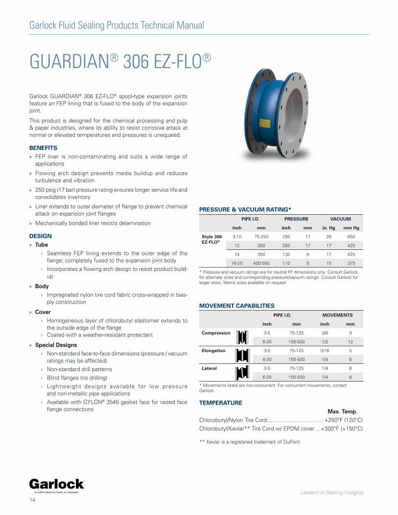
GUARDIAN® 306 EZ-FLO®
Garlock GUARDIAN® 306 EZ-FLO® spool-type expansion joints feature an FEP lining that is fused to the body of the expansion joint.
This product is designed for the chemical processing and pulp & paper industries, where its ability to resist corrosive attack at normal or elevated temperatures and pressures is unequaled.
BENEFITS » FEP liner is non-contaminating and suits a wide range of
applications
» Flowing arch design prevents media buildup and reduces turbulence and vibration
» 250 psig (17 bar) pressure rating ensures longer service life and consolidates inventory
» Liner extends to outer diameter of flange to prevent chemical attack on expansion joint flanges
» Mechanically bonded liner resists delamination
DESIGN » Tube
› Seamless FEP lining extends to the outer edge of the flange; completely fused to the expansion joint body
› Incorporates a flowing arch design to resist product build-up
» Body › Impregnated nylon tire cord fabric cross-wrapped in bias-
ply construction
» Cover › Homogeneous layer of chlorobutyl elastomer extends to
the outside edge of the flange › Coated with a weather-resistant protectant
» Special Designs › Non-standard face-to-face dimensions (pressure / vacuum
ratings may be affected)
› Non-standard drill patterns
› Blind flanges (no drilling)
› Lightweight designs available for low pressure and non-metallic pipe applications
› Available with GYLON® 3545 gasket face for raised face flange connections
TEMPERATURE Max. Temp. Chlorobutyl/Nylon Tire Cord .................................... +250°F (120°C)
Chlorobutyl/Kevlar** Tire Cord w/ EPDM cover ... +300°F (+150°C)
** Kevlar is a registered trademark of DuPont
MOVEMENT CAPABILITIES
PIPE I.D. MOVEMENTS
inch mm inch mm
Compression 3-5 75-125 3/8 9
6-20 150-500 1/2 12
Elongation 3-5 75-125 3/16 5
6-20 150-500 1/4 6
Lateral 3-5 75-125 1/4 6
6-20 150-500 1/4 6
* Movements listed are non-concurrent. For concurrent movements, contact Garlock.
PRESSURE & VACUUM RATING*
PIPE I.D. PRESSURE VACUUM
inch mm inch mm in. Hg mm Hg
Style 306 EZ-FLO®
3-10 75-250 250 17 26 650
12 300 250 17 17 425
14 350 130 9 17 425
16-20 400-500 110 8 15 375
* Pressure and vacuum ratings are for neutral FF dimensions only. Consult Garlock for alternate sizes and corresponding pressure/vacuum ratings. Consult Garlock for larger sizes. Metric sizes available on request.
Garlock Fluid Sealing Products Technical Manual
Leaders in Sealing Integrity
15
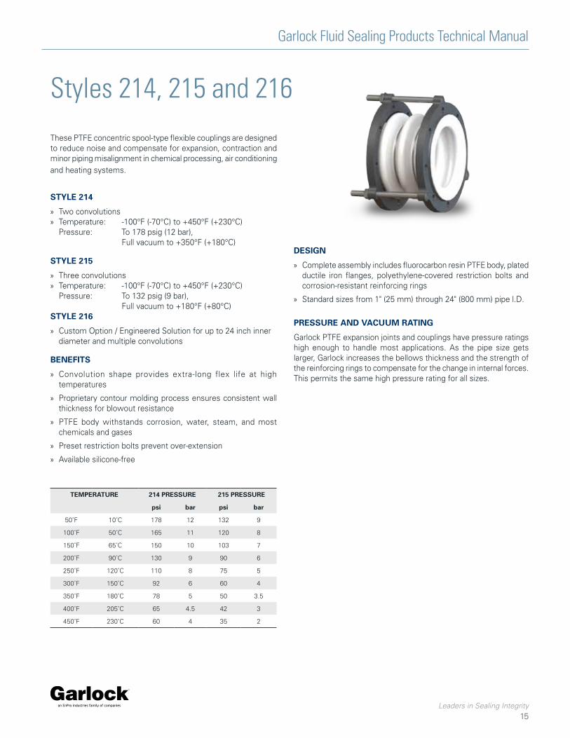
Styles 214, 215 and 216
These PTFE concentric spool-type flexible couplings are designed to reduce noise and compensate for expansion, contraction and minor piping misalignment in chemical processing, air conditioning and heating systems.
STYLE 214
» Two convolutions » Temperature: -100°F (-70°C) to +450°F (+230°C)
Pressure: To 178 psig (12 bar), Full vacuum to +350°F (+180°C)
STYLE 215
» Three convolutions » Temperature: -100°F (-70°C) to +450°F (+230°C)
Pressure: To 132 psig (9 bar), Full vacuum to +180°F (+80°C)
STYLE 216
» Custom Option / Engineered Solution for up to 24 inch inner diameter and multiple convolutions
BENEFITS
» Convolution shape provides extra-long flex life at high temperatures
» Proprietary contour molding process ensures consistent wall thickness for blowout resistance
» PTFE body withstands corrosion, water, steam, and most chemicals and gases
» Preset restriction bolts prevent over-extension
» Available silicone-free
PRESSURE AND VACUUM RATING
Garlock PTFE expansion joints and couplings have pressure ratings high enough to handle most applications. As the pipe size gets larger, Garlock increases the bellows thickness and the strength of the reinforcing rings to compensate for the change in internal forces. This permits the same high pressure rating for all sizes.
TEMPERATURE 214 PRESSURE 215 PRESSURE
psi bar psi bar
50˚F 10˚C 178 12 132 9
100˚F 50˚C 165 11 120 8
150˚F 65˚C 150 10 103 7
200˚F 90˚C 130 9 90 6
250˚F 120˚C 110 8 75 5
300˚F 150˚C 92 6 60 4
350˚F 180˚C 78 5 50 3.5
400˚F 205˚C 65 4.5 42 3
450˚F 230˚C 60 4 35 2
DESIGN
» Complete assembly includes fluorocarbon resin PTFE body, plated ductile iron flanges, polyethylene-covered restriction bolts and corrosion-resistant reinforcing rings
» Standard sizes from 1" (25 mm) through 24" (800 mm) pipe l.D.
Garlock Fluid Sealing Products Technical Manual
Leaders in Sealing Integrity
16
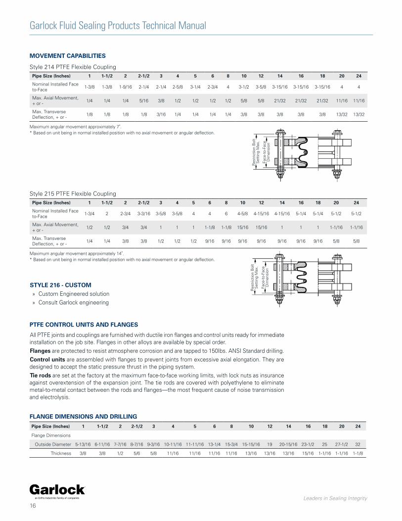
MOVEMENT CAPABILITIES
Pipe Size (Inches) 1 1-1/2 2 2-1/2 3 4 5 6 8 10 12 14 16 18 20 24
Nominal Installed Face to-Face
1-3/8 1-3/8 1-9/16 2-1/4 2-1/4 2-5/8 3-1/4 2-3/4 4 3-1/2 3-5/8 3-15/16 3-15/16 3-15/16 4 4
Max. Axial Movement, + or -
1/4 1/4 1/4 5/16 3/8 1/2 1/2 1/2 1/2 5/8 5/8 21/32 21/32 21/32 11/16 11/16
Max. Transverse Deflection, + or -
1/8 1/8 1/8 1/8 3/16 1/4 1/4 1/4 1/4 3/8 3/8 3/8 3/8 3/8 13/32 13/32
Maximum angular movement approximately 7˚.* Based on unit being in normal installed position with no axial movement or angular deflection.
Res
tric
tion
Bol
tS
ettin
g M
ax.
Face
-to-
Face
Dim
ensi
on
Style 214 PTFE Flexible Coupling
Pipe Size (Inches) 1 1-1/2 2 2-1/2 3 4 5 6 8 10 12 14 16 18 20 24
Nominal Installed Face to-Face
1-3/4 2 2-3/4 3-3/16 3-5/8 3-5/8 4 4 6 4-5/8 4-15/16 4-15/16 5-1/4 5-1/4 5-1/2 5-1/2
Max. Axial Movement, + or -
1/2 1/2 3/4 3/4 1 1 1 1-1/8 1-1/8 15/16 15/16 1 1 1 1-1/16 1-1/16
Max. Transverse Deflection, + or -
1/4 1/4 3/8 3/8 1/2 1/2 1/2 9/16 9/16 9/16 9/16 9/16 9/16 9/16 5/8 5/8
Maximum angular movement approximately 14˚.* Based on unit being in normal installed position with no axial movement or angular deflection.
Style 215 PTFE Flexible Coupling
PTFE CONTROL UNITS AND FLANGES
All PTFE joints and couplings are furnished with ductile iron flanges and control units ready for immediate installation on the job site. Flanges in other alloys are available by special order.
Flanges are protected to resist atmosphere corrosion and are tapped to 150Ibs. ANSI Standard drilling.
Control units are assembled with flanges to prevent joints from excessive axial elongation. They are designed to accept the static pressure thrust in the piping system.
Tie rods are set at the factory at the maximum face-to-face working limits, with lock nuts as insurance against overextension of the expansion joint. The tie rods are covered with polyethylene to eliminate metal-to-metal contact between the rods and flanges—the most frequent cause of noise transmission and electrolysis.
Pipe Size (Inches) 1 1-1/2 2 2-1/2 3 4 5 6 8 10 12 14 16 18 20 24
Flange Dimensions
Outside Diameter 5-13/16 6-11/16 7-7/16 8-7/16 9-3/16 10-11/16 11-11/16 13-1/4 15-3/4 15-15/16 19 20-15/16 23-1/2 25 27-1/2 32
Thickness 3/8 3/8 1/2 5/6 5/8 11/16 11/16 11/16 11/16 13/16 13/16 13/16 15/16 1-1/16 1-1/16 1-1/8
FLANGE DIMENSIONS AND DRILLING
Res
tric
tion
Bol
tS
ettin
g M
ax.
Face
-to-
Face
Dim
ensi
on
STYLE 216 - CUSTOM » Custom Engineered solution
» Consult Garlock engineering
Garlock Fluid Sealing Products Technical Manual
Leaders in Sealing Integrity
17
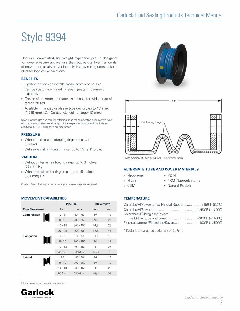
Style 9394
This multi-convoluted, lightweight expansion joint is designed for lower pressure applications that require significant amounts of movement, axially and/or laterally. Its low spring rates make it ideal for load cell applications.
BENEFITS » Lightweight design installs easily, costs less to ship
» Can be custom-designed for even greater movement capability
» Choice of construction materials suitable for wide range of temperatures
» Available in flanged or sleeve type design, up to 48" max. (1,219 mm) I.D. *Contact Garlock for larger ID sizes
Note: Flanged designs require retaining rings for an effective seal. Sleeve type requires clamps; the overall length of the expansion joint should include an additional 4" (101.6mm) for clamping space.
PRESSURE » Without external reinforcing rings: up to 3 psi
(0.2 bar)
» With external reinforcing rings: up to 15 psi (1.0 bar)
VACUUM » Without internal reinforcing rings: up to 3 inches
(75 mm) Hg
» With internal reinforcing rings: up to 15 inches (381 mm) Hg
Contact Garlock if higher vacuum or pressure ratings are required.
F-F
Reinforcing Rings
Cross Section of Style 9394 with Reinforcing Rings
ALTERNATE TUBE AND COVER MATERIALS
» Neoprene
» Nitrile
» CSM
» PDM
» FKM Fluoroelastomer
» Natural Rubber
MOVEMENT CAPABILITIES
Type Movement
Pipe I.D. Movement
inch mm inch mm
Compression 2 - 6 50 - 150 3/4 19
8 - 10 200 - 250 7/8 22
12 - 18 300 - 450 1-1/8 28
20 - up 500 - up 1-5/8 41
Elongation 2 - 6 50 - 150 5/8 16
8 - 10 200 - 250 3/4 19
12 - 18 300 - 450 1 25
20 & up 500 & up 1-5/8 6
Lateral 2-6 50-150 5/8 16
8 - 10 200 - 250 3/4 19
12 - 18 300 - 450 1 25
20 & up 500 & up 1-1/4 31
Movements listed are per convolution
TEMPERATURE
Chlorobutyl/Polyester w/ Natural Rubber ................. +180°F (82°C)
Chlorobutyl/Polyester ........................................... +250°F (+120°C)Chlorobutyl/Fiberglass/Kevlar* w/ EPDM tube and cover ............................... +300°F (+150°C)Fluoroelastomer/Fiberglass/Kevlar ........................ +400°F (+250°C)
* Kevlar is a registered trademark of DuPont.
Garlock Fluid Sealing Products Technical Manual
Leaders in Sealing Integrity
18
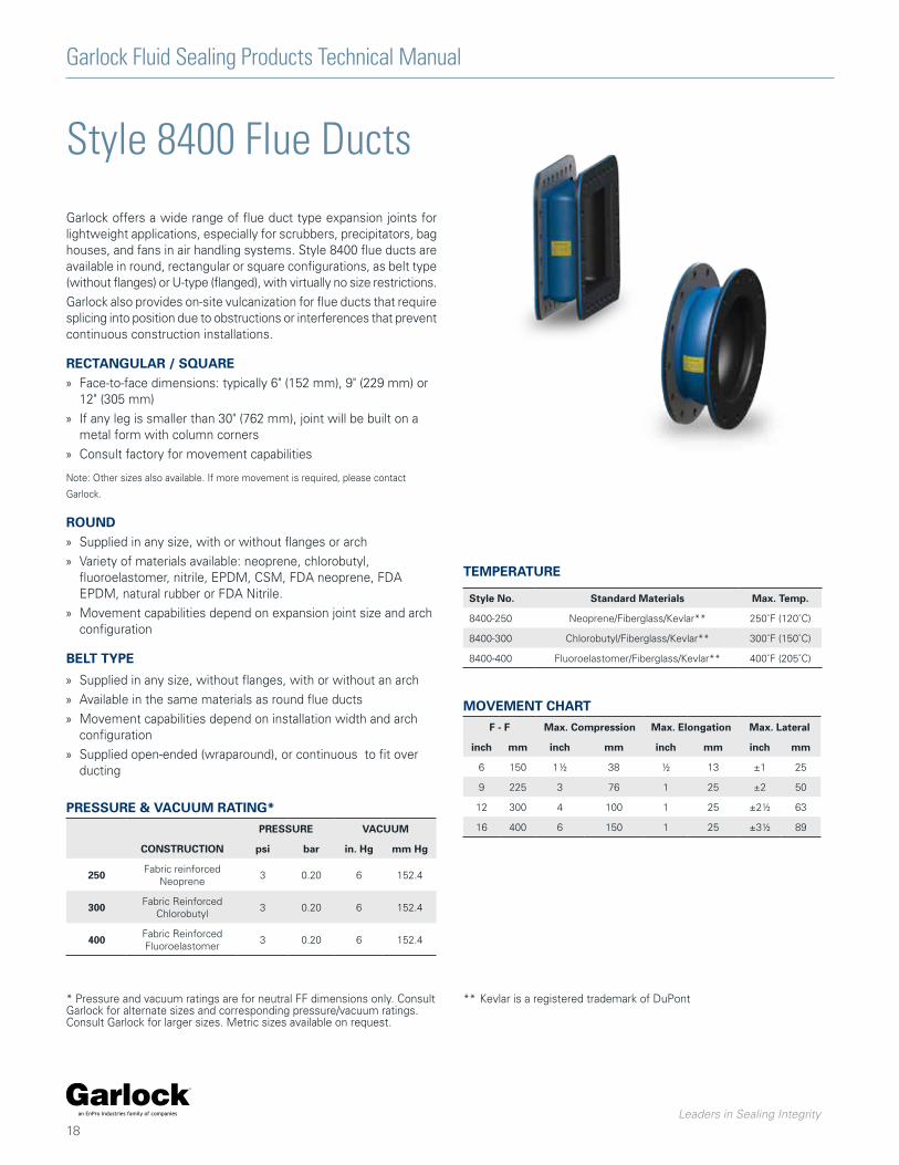
Style 8400 Flue Ducts
Garlock offers a wide range of flue duct type expansion joints for lightweight applications, especially for scrubbers, precipitators, bag houses, and fans in air handling systems. Style 8400 flue ducts are available in round, rectangular or square configurations, as belt type (without flanges) or U-type (flanged), with virtually no size restrictions.
Garlock also provides on-site vulcanization for flue ducts that require splicing into position due to obstructions or interferences that prevent continuous construction installations.
RECTANGULAR / SQUARE » Face-to-face dimensions: typically 6" (152 mm), 9" (229 mm) or
12" (305 mm)
» If any leg is smaller than 30" (762 mm), joint will be built on a metal form with column corners
» Consult factory for movement capabilities
Note: Other sizes also available. If more movement is required, please contact
Garlock.
ROUND » Supplied in any size, with or without flanges or arch
» Variety of materials available: neoprene, chlorobutyl, fluoroelastomer, nitrile, EPDM, CSM, FDA neoprene, FDA EPDM, natural rubber or FDA Nitrile.
» Movement capabilities depend on expansion joint size and arch configuration
BELT TYPE
» Supplied in any size, without flanges, with or without an arch
» Available in the same materials as round flue ducts
» Movement capabilities depend on installation width and arch configuration
» Supplied open-ended (wraparound), or continuous to fit over ducting
TEMPERATURE
Style No. Standard Materials Max. Temp.
8400-250 Neoprene/Fiberglass/Kevlar** 250˚F (120˚C)
8400-300 Chlorobutyl/Fiberglass/Kevlar** 300˚F (150˚C)
8400-400 Fluoroelastomer/Fiberglass/Kevlar** 400˚F (205˚C)
MOVEMENT CHART
F - F Max. Compression Max. Elongation Max. Lateral
inch mm inch mm inch mm inch mm
6 150 1½ 38 ½ 13 ±1 25
9 225 3 76 1 25 ±2 50
12 300 4 100 1 25 ±2½ 63
16 400 6 150 1 25 ±3½ 89
PRESSURE & VACUUM RATING*
PRESSURE VACUUM
CONSTRUCTION psi bar in. Hg mm Hg
250 Fabric reinforced Neoprene
3 0.20 6 152.4
300 Fabric Reinforced Chlorobutyl
3 0.20 6 152.4
400 Fabric Reinforced Fluoroelastomer
3 0.20 6 152.4
* Pressure and vacuum ratings are for neutral FF dimensions only. Consult Garlock for alternate sizes and corresponding pressure/vacuum ratings. Consult Garlock for larger sizes. Metric sizes available on request.
** Kevlar is a registered trademark of DuPont
Garlock Fluid Sealing Products Technical Manual
Leaders in Sealing Integrity
19
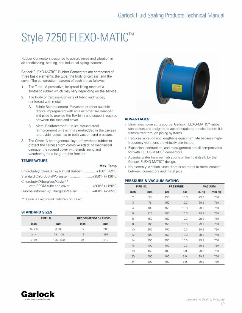
Style 7250 FLEXO-MATIC™
Rubber Connectors designed to absorb noise and vibration in air-conditioning, heating, and industrial piping systems.
Garlock FLEXO-MATIC™ Rubber Connectors are composed of three basic elements: the tube, the body or carcass, and the cover. The construction features of each are as follows:
1. The Tube - A protective, leakproof lining made of a synthetic rubber which may vary depending on the service.
2. The Body or Carcass–Consists of fabric and rubber, reinforced with metal.
A. Fabric Reinforcement–Polyester, or other suitable fabrics impregnated with an elastomer are wrapped and plied to provide the flexibility and support required between the tube and cover.
B. Metal Reinforcement–Helical-wound steel reinforcement wire is firmly embedded in the carcass to provide resistance to both vacuum and pressure.
3. The Cover–A homogeneous layer of synthetic rubber to protect the carcass from corrosive attack or mechanical damage, the rugged cover withstands aging and weathering for a long, trouble-free life.
ADVANTAGES » Eliminates noise at its source. Garlock FLEXO-MATIC™ rubber
connectors are designed to absorb equipment noise before it is transmitted through piping systems.
» Reduces vibration and lengthens equipment life because high- frequency vibrations are virtually eliminated.
» Expansion, contraction, and misalignment are all compensated for with FLEXO-MATIC™ connectors.
» Absorbs water hammer, vibrations of the fluid itself, by the Garlock FLEXO-MATIC™ design.
» No electrolytic action since there is no metal-to-metal contact between connectors and metal pipe.
PRESSURE & VACUUM RATING
PIPE I.D. PRESSURE VACUUM
inch mm psi bar in. Hg mm Hg
2 50 150 10.3 29.9 750
3 75 150 10.3 29.9 750
4 100 150 10.3 29.9 750
5 125 150 10.3 29.9 750
6 150 150 10.3 29.9 750
8 200 150 10.3 29.9 750
10 250 150 10.3 29.9 750
12 300 150 10.3 29.9 750
14 350 150 10.3 29.9 750
16 400 150 10.3 29.9 750
18 450 100 6.9 29.9 750
20 500 100 6.9 29.9 750
24 600 100 6.9 29.9 750
TEMPERATURE Max. Temp. Chlorobutyl/Polyester w/ Natural Rubber .............. +180°F (82°C)
Standard Chlorobutyl/Polyester .........................+250°F (+120°C)
Chlorobutyl/Fiberglass/Kevlar** with EPDM tube and cover .......................+300°F (+150°C)
Fluoroelastomer w/ Fiberglass/Kevlar ................+400°F (+205°C)
** Kevlar is a registered trademark of DuPont
STANDARD SIZES
PIPE I.D. RECOMMENDED LENGTH
inch mm inch mm
0 - 2.5 0 - 65 12 305
3 - 4 75 - 100 18 457
5 - 24 125 - 600 24 610
Garlock Fluid Sealing Products Technical Manual
Leaders in Sealing Integrity
20
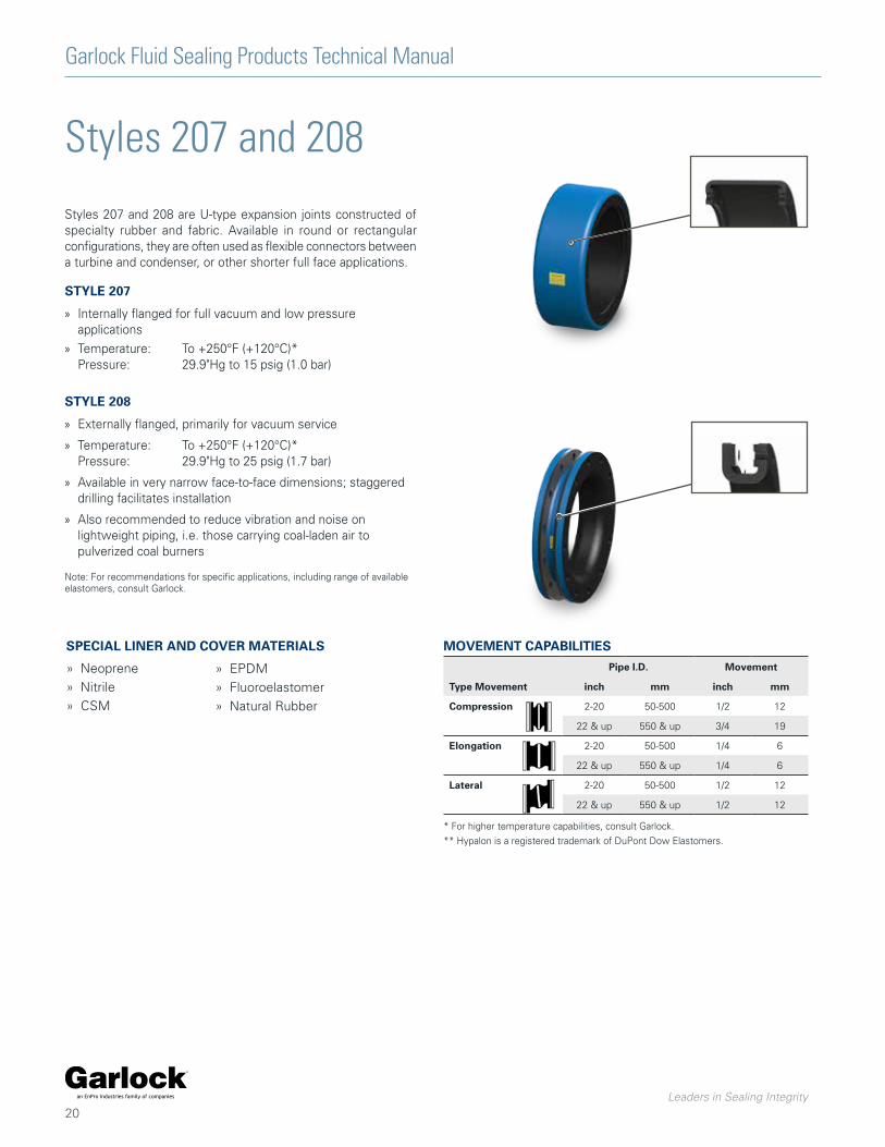
Styles 207 and 208
Styles 207 and 208 are U-type expansion joints constructed of specialty rubber and fabric. Available in round or rectangular configurations, they are often used as flexible connectors between a turbine and condenser, or other shorter full face applications.
STYLE 207
» Internally flanged for full vacuum and low pressure applications
» Temperature: To +250°F (+120°C)* Pressure: 29.9"Hg to 15 psig (1.0 bar)
STYLE 208
» Externally flanged, primarily for vacuum service
» Temperature: To +250°F (+120°C)* Pressure: 29.9"Hg to 25 psig (1.7 bar)
» Available in very narrow face-to-face dimensions; staggered drilling facilitates installation
» Also recommended to reduce vibration and noise on lightweight piping, i.e. those carrying coal-laden air to pulverized coal burners
Note: For recommendations for specific applications, including range of available elastomers, consult Garlock.
SPECIAL LINER AND COVER MATERIALS
» Neoprene
» Nitrile
» CSM
» EPDM
» Fluoroelastomer
» Natural Rubber
* For higher temperature capabilities, consult Garlock.
** Hypalon is a registered trademark of DuPont Dow Elastomers.
MOVEMENT CAPABILITIES
Type Movement
Pipe I.D. Movement
inch mm inch mm
Compression 2-20 50-500 1/2 12
22 & up 550 & up 3/4 19
Elongation 2-20 50-500 1/4 6
22 & up 550 & up 1/4 6
Lateral 2-20 50-500 1/2 12
22 & up 550 & up 1/2 12
Garlock Fluid Sealing Products Technical Manual
Leaders in Sealing Integrity
21
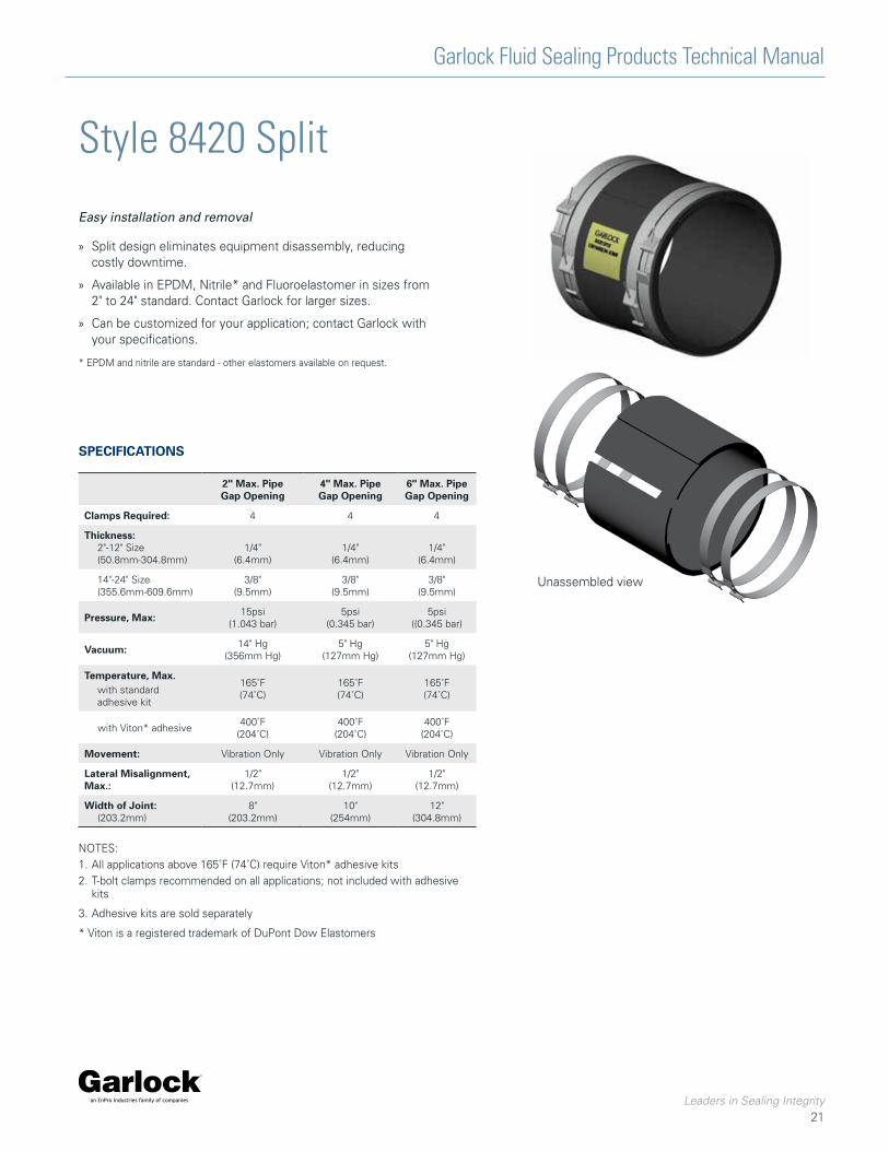
Style 8420 Split
Easy installation and removal
» Split design eliminates equipment disassembly, reducing costly downtime.
» Available in EPDM, Nitrile* and Fluoroelastomer in sizes from 2" to 24" standard. Contact Garlock for larger sizes.
» Can be customized for your application; contact Garlock with your specifications.
* EPDM and nitrile are standard - other elastomers available on request.
Unassembled view
SPECIFICATIONS
2" Max. Pipe Gap Opening
4" Max. Pipe Gap Opening
6" Max. Pipe Gap Opening
Clamps Required: 4 4 4
Thickness:2"-12" Size(50.8mm-304.8mm)
1/4"(6.4mm)
1/4"(6.4mm)
1/4"(6.4mm)
14"-24" Size(355.6mm-609.6mm)
3/8"(9.5mm)
3/8"(9.5mm)
3/8"(9.5mm)
Pressure, Max: 15psi(1.043 bar)
5psi(0.345 bar)
5psi((0.345 bar)
Vacuum: 14" Hg(356mm Hg)
5" Hg(127mm Hg)
5" Hg(127mm Hg)
Temperature, Max.with standard adhesive kit
165˚F(74˚C)
165˚F(74˚C)
165˚F(74˚C)
with Viton* adhesive400˚F
(204˚C)400˚F
(204˚C)400˚F
(204˚C)
Movement: Vibration Only Vibration Only Vibration Only
Lateral Misalignment, Max.:
1/2"(12.7mm)
1/2"(12.7mm)
1/2"(12.7mm)
Width of Joint:(203.2mm)
8"(203.2mm)
10"(254mm)
12"(304.8mm)
NOTES:1. All applications above 165˚F (74˚C) require Viton* adhesive kits2. T-bolt clamps recommended on all applications; not included with adhesive
kits
3. Adhesive kits are sold separately
* Viton is a registered trademark of DuPont Dow Elastomers
Garlock Fluid Sealing Products Technical Manual
Leaders in Sealing Integrity
22
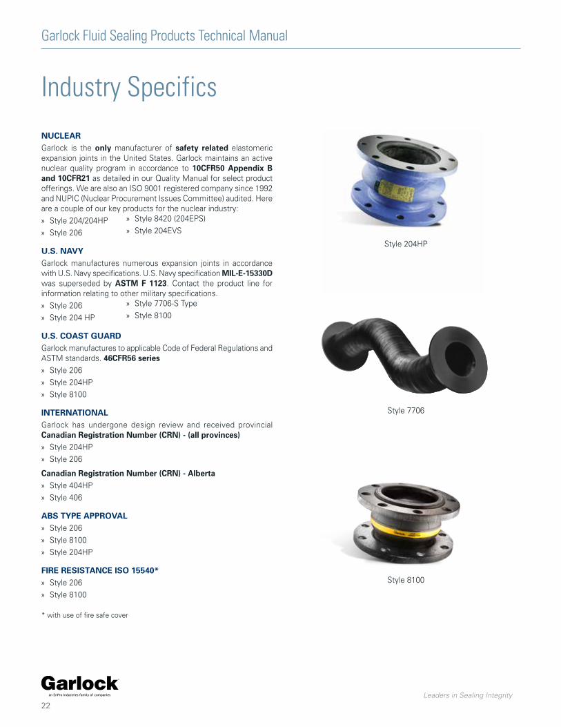
Industry Specifics
NUCLEARGarlock is the only manufacturer of safety related elastomeric expansion joints in the United States. Garlock maintains an active nuclear quality program in accordance to 10CFR50 Appendix B and 10CFR21 as detailed in our Quality Manual for select product offerings. We are also an ISO 9001 registered company since 1992 and NUPIC (Nuclear Procurement Issues Committee) audited. Here are a couple of our key products for the nuclear industry:
» Style 204/204HP
» Style 206
U.S. NAVYGarlock manufactures numerous expansion joints in accordance with U.S. Navy specifications. U.S. Navy specification MIL-E-15330D was superseded by ASTM F 1123. Contact the product line for information relating to other military specifications.
» Style 206
» Style 204 HP
U.S. COAST GUARDGarlock manufactures to applicable Code of Federal Regulations and ASTM standards. 46CFR56 series » Style 206
» Style 204HP
» Style 8100
INTERNATIONALGarlock has undergone design review and received provincial Canadian Registration Number (CRN) - (all provinces) » Style 204HP
» Style 206
Canadian Registration Number (CRN) - Alberta » Style 404HP
» Style 406
ABS TYPE APPROVAL » Style 206
» Style 8100
» Style 204HP
FIRE RESISTANCE ISO 15540* » Style 206
» Style 8100
* with use of fire safe cover
» Style 8420 (204EPS)
» Style 204EVS
» Style 7706-S Type
» Style 8100
Style 204HP
Style 7706
Style 8100
Garlock Fluid Sealing Products Technical Manual
Leaders in Sealing Integrity
23
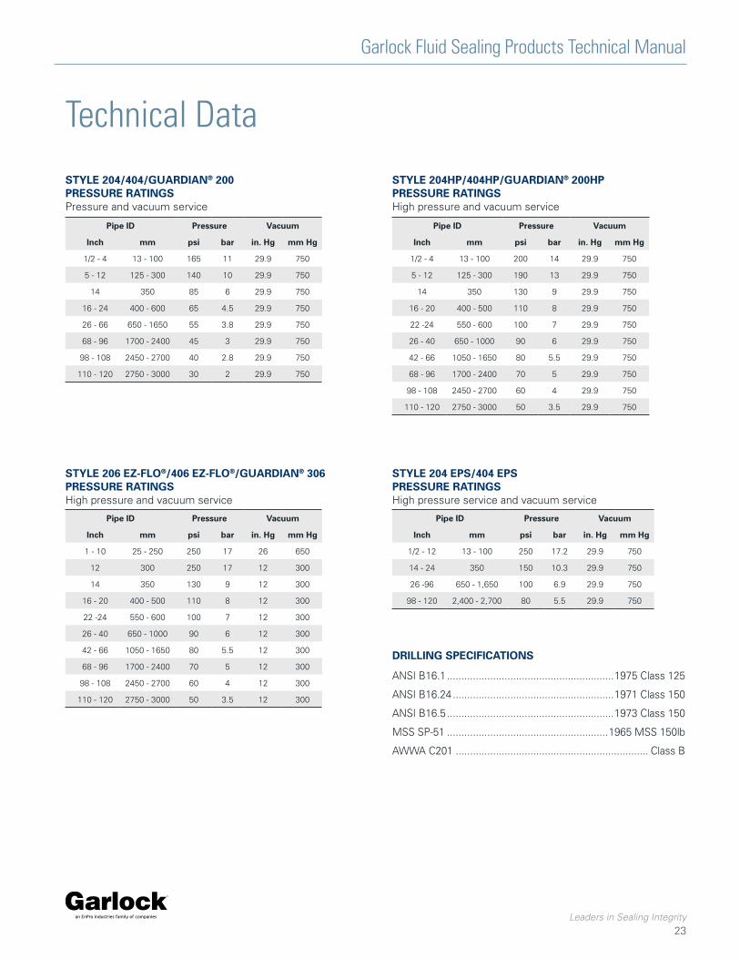
Technical Data
Pipe ID Pressure Vacuum
Inch mm psi bar in. Hg mm Hg
1/2 - 4 13 - 100 165 11 29.9 750
5 - 12 125 - 300 140 10 29.9 750
14 350 85 6 29.9 750
16 - 24 400 - 600 65 4.5 29.9 750
26 - 66 650 - 1650 55 3.8 29.9 750
68 - 96 1700 - 2400 45 3 29.9 750
98 - 108 2450 - 2700 40 2.8 29.9 750
110 - 120 2750 - 3000 30 2 29.9 750
STYLE 204/404/GUARDIAN® 200 PRESSURE RATINGSPressure and vacuum service
Pipe ID Pressure Vacuum
Inch mm psi bar in. Hg mm Hg
1/2 - 4 13 - 100 200 14 29.9 750
5 - 12 125 - 300 190 13 29.9 750
14 350 130 9 29.9 750
16 - 20 400 - 500 110 8 29.9 750
22 -24 550 - 600 100 7 29.9 750
26 - 40 650 - 1000 90 6 29.9 750
42 - 66 1050 - 1650 80 5.5 29.9 750
68 - 96 1700 - 2400 70 5 29.9 750
98 - 108 2450 - 2700 60 4 29.9 750
110 - 120 2750 - 3000 50 3.5 29.9 750
STYLE 204HP/404HP/GUARDIAN® 200HP PRESSURE RATINGSHigh pressure and vacuum service
Pipe ID Pressure Vacuum
Inch mm psi bar in. Hg mm Hg
1 - 10 25 - 250 250 17 26 650
12 300 250 17 12 300
14 350 130 9 12 300
16 - 20 400 - 500 110 8 12 300
22 -24 550 - 600 100 7 12 300
26 - 40 650 - 1000 90 6 12 300
42 - 66 1050 - 1650 80 5.5 12 300
68 - 96 1700 - 2400 70 5 12 300
98 - 108 2450 - 2700 60 4 12 300
110 - 120 2750 - 3000 50 3.5 12 300
Pipe ID Pressure Vacuum
Inch mm psi bar in. Hg mm Hg
1/2 - 12 13 - 100 250 17.2 29.9 750
14 - 24 350 150 10.3 29.9 750
26 -96 650 - 1,650 100 6.9 29.9 750
98 - 120 2,400 - 2,700 80 5.5 29.9 750
STYLE 206 EZ-FLO®/406 EZ-FLO®/GUARDIAN® 306 PRESSURE RATINGSHigh pressure and vacuum service
STYLE 204 EPS/404 EPS PRESSURE RATINGSHigh pressure service and vacuum service
DRILLING SPECIFICATIONS
ANSI B16.1 ..........................................................1975 Class 125
ANSI B16.24 ........................................................1971 Class 150
ANSI B16.5 ..........................................................1973 Class 150
MSS SP-51 ........................................................1965 MSS 150lb
AWWA C201 ................................................................... Class B
Garlock Fluid Sealing Products Technical Manual
Leaders in Sealing Integrity
24
716
716
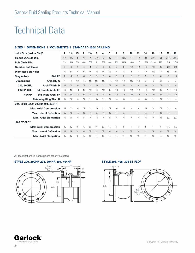
SIZES | DIMENSIONS | MOVEMENTS | STANDARD 150# DRILLING
Technical Data
STYLE 200, 200HP, 204, 204HP, 404, 404HP STYLE 206, 406, 306 EZ-FLO®
FFRA
C
DI.D.
O.D.
Steel Retaining
Rings
RA
B
I.D.
O.D.
I.D.
SplitRetaining
Ring
All specifications in inches unless otherwise noted.
B
Joint Size (inside Dia.)1 1 1¼ 1½ 2 2½ 3 4 5 6 8 10 12 14 16 18 20 22 24 26 28 30 32 34 36 40 42 48 50 54 60 66 72 78 84 90 96 108 120
Flange Outside Dia. 4¼ 4⅝ 5 6 7 7½ 9 10 11 13½ 17 19 21 23½ 25 27½ 29½ 32 34¼ 36½ 38¾ 41¾ 43¾ 46 50¾ 53 59½ 61¾ 66¼ 73 80 86½ 93 99¾ 106½ 113¼ 126¾ 140¼
Bolt Circle Dia. 3⅛ 3½ 3⅞ 4¾ 5½ 6 7½ 8½ 9½ 11¾ 14¼ 17 18¾ 21½ 22¾ 25 27¼ 29½ 31¾ 34 36 38½ 40½ 42¾ 47¼ 49½ 56 58¼ 62¾ 69¼ 76 82½ 88¾ 95½ 102 108½ 120¾ 132¾
Number Bolt Holes 4 4 4 4 4 4 8 8 8 8 12 12 12 16 16 20 20 20 24 28 28 28 32 32 36 36 44 44 44 52 52 60 60 64 68 68 72 76
Diameter Bolt Holes ⅝ ⅝ ⅝ ¾ ¾ ¾ ¾ ⅞ ⅞ ⅞ 1 1 1⅛ 1⅛ 1¼ 1¼ 1⅜ 1⅜ 1⅜ 1⅜ 1⅜ 1⅝ 1⅝ 1⅝ 1⅝ 1⅝ 1⅝ 1⅞ 2 2 2 2 2⅛ 2¼ 2⅜ 2½ 2½ 2½
Single Arch Std FF 6 6 6 6 6 6 6 6 6 6 8 8 8 8 8 8 10 10 10 10 10 10 10 10 10 12 12 12 12 12 12 12 12 12 12 12 12 12
Dimensions Arch Ht. C 1 1 1¼ 1¼ 1¼ 1¼ 1¼ 1¼ 1¼ 1½ 1½ 1½ 2 2 2 2 2 2 2¼ 2¼ 2¼ 2¼ 2¼ 2¼ 2¼ 2½ 2½ 2½ 2½ 2½ 2½ 2½ 2½ 2½ 2½ 2½ 2½ 2½
200, 200HP, Arch Width D ½ ½ ½ ½ ½ ½ ½ ½ ½ ¾ ¾ ¾ ¾ ¾ ¾ ⅞ ⅞ ⅞ 1 1 1 1 1 1 1 1⅛ 1⅛ 1⅛ 1⅛ 1⅛ 1⅛ 1⅛ 1⅛ 1⅛ 1⅛ 1⅛ 1⅛ 1⅛
204HP, 404, Std Double Arch FF 10 10 10 10 10 10 10 10 10 10 12 12 12 12 12 14 14 14 14 14 14 14 14 14 14 16 16 16 16 16 16 16 18 18 18 18 18 18
404HP Std Triple Arch FF 14 14 14 14 14 14 14 14 14 14 16 16 16 16 16 18 18 18 18 18 18 18 18 18 18 20 20 20 20 20 20 20 22 22 22 22 22 22
Retaining Ring Thk. R ⅜ ⅜ ⅜ ⅜ ⅜ ⅜ ⅜ ⅜ ⅜ ⅜ ⅜ ⅜ ⅜ ⅜ ⅜ ⅜ ⅜ ⅜ ⅜ ⅜ ⅜ ⅜ ⅜ ⅜ ⅜ ⅜ ⅜ ⅜ ⅜ ⅜ ⅜ ⅜ ⅜ ⅜ ⅜ ⅜ ⅜ ⅜
204, 204HP, 200, 200HP, 404, 404HP
Max. Axial Compression ¼ ¼ ¼ ½ ½ ½ ½ ½ ½ ¾ ¾ ¾ ¾ ¾ ¾ ⅞ ⅞ ⅞ 1 1 1 1 1 1 1 1⅛ 1⅛ 1⅛ 1⅛ 1⅛ 1⅛ 1⅛ 1⅛ 1⅛ 1⅛ 1⅛ 1⅛ 1⅛
Max. Lateral Deflection ¼ ¼ ¼ ½ ½ ½ ½ ½ ½ ½ ½ ½ ½ ½ ½ ½ ½ ½ ½ ½ ½ ½ ½ ½ ½ ½ ½ ½ ½ ½ ½ ½ ½ ½ ½ ½ ½ ½
Max. Axial Elongation ⅛ ⅛ ⅛ ¼ ¼ ¼ ¼ ¼ ¼ ⅜ ⅜ ⅜ ⅜ ⅜ ⅜ ½ ½ ½ ½ ½ ½ ½ ½ ½ ½ ½ ½ ½ ½ ½ ½ ½ ½ ½ ½
206 EZ-FLO®
Max. Axial Compression ¾ ¾ ¾ ¾ ¾ ¾ ¾ ¾ 1 1 1 1 1 1 1 1⅛ 1⅛ 1⅛ 1¼ 1¼ 1¼ 1¼ 1¼ 1¼ 1¼ 1⅜ 1⅜ 1⅜ 1⅜ 1⅜ 1⅜ 1⅜ 1⅜ 1⅜ 1⅜ 1⅜ 1⅜ 1⅜
Max. Lateral Deflection ½ ½ ½ ½ ½ ½ ½ ½ ½ ½ ½ ½ ½ ½ ½ ½ ½ ½ ½ ½ ½ ½ ½ ½ ½ ½ ½ ½ ½ ½ ½ ½ ½ ½ ½ ½ ½ ½
Max. Axial Elongation ⅜ ⅜ ⅜ ⅜ ⅜ ⅜ ⅜ ⅜ ½ ½ ½ ½ ½ ½ ½ ½ ½ ½ ½ ½ ½ ½ ½ ½ ½ ½ ½ ½ ½ ½ ½ ½ ½ ½ ½ ½ ½ ½
Garlock Fluid Sealing Products Technical Manual
Leaders in Sealing Integrity
25
716
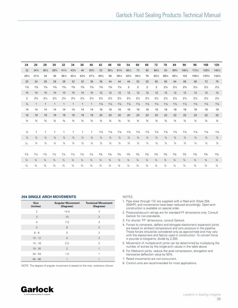
Joint Size (inside Dia.)1 1 1¼ 1½ 2 2½ 3 4 5 6 8 10 12 14 16 18 20 22 24 26 28 30 32 34 36 40 42 48 50 54 60 66 72 78 84 90 96 108 120
Flange Outside Dia. 4¼ 4⅝ 5 6 7 7½ 9 10 11 13½ 17 19 21 23½ 25 27½ 29½ 32 34¼ 36½ 38¾ 41¾ 43¾ 46 50¾ 53 59½ 61¾ 66¼ 73 80 86½ 93 99¾ 106½ 113¼ 126¾ 140¼
Bolt Circle Dia. 3⅛ 3½ 3⅞ 4¾ 5½ 6 7½ 8½ 9½ 11¾ 14¼ 17 18¾ 21½ 22¾ 25 27¼ 29½ 31¾ 34 36 38½ 40½ 42¾ 47¼ 49½ 56 58¼ 62¾ 69¼ 76 82½ 88¾ 95½ 102 108½ 120¾ 132¾
Number Bolt Holes 4 4 4 4 4 4 8 8 8 8 12 12 12 16 16 20 20 20 24 28 28 28 32 32 36 36 44 44 44 52 52 60 60 64 68 68 72 76
Diameter Bolt Holes ⅝ ⅝ ⅝ ¾ ¾ ¾ ¾ ⅞ ⅞ ⅞ 1 1 1⅛ 1⅛ 1¼ 1¼ 1⅜ 1⅜ 1⅜ 1⅜ 1⅜ 1⅝ 1⅝ 1⅝ 1⅝ 1⅝ 1⅝ 1⅞ 2 2 2 2 2⅛ 2¼ 2⅜ 2½ 2½ 2½
Single Arch Std FF 6 6 6 6 6 6 6 6 6 6 8 8 8 8 8 8 10 10 10 10 10 10 10 10 10 12 12 12 12 12 12 12 12 12 12 12 12 12
Dimensions Arch Ht. C 1 1 1¼ 1¼ 1¼ 1¼ 1¼ 1¼ 1¼ 1½ 1½ 1½ 2 2 2 2 2 2 2¼ 2¼ 2¼ 2¼ 2¼ 2¼ 2¼ 2½ 2½ 2½ 2½ 2½ 2½ 2½ 2½ 2½ 2½ 2½ 2½ 2½
200, 200HP, Arch Width D ½ ½ ½ ½ ½ ½ ½ ½ ½ ¾ ¾ ¾ ¾ ¾ ¾ ⅞ ⅞ ⅞ 1 1 1 1 1 1 1 1⅛ 1⅛ 1⅛ 1⅛ 1⅛ 1⅛ 1⅛ 1⅛ 1⅛ 1⅛ 1⅛ 1⅛ 1⅛
204HP, 404, Std Double Arch FF 10 10 10 10 10 10 10 10 10 10 12 12 12 12 12 14 14 14 14 14 14 14 14 14 14 16 16 16 16 16 16 16 18 18 18 18 18 18
404HP Std Triple Arch FF 14 14 14 14 14 14 14 14 14 14 16 16 16 16 16 18 18 18 18 18 18 18 18 18 18 20 20 20 20 20 20 20 22 22 22 22 22 22
Retaining Ring Thk. R ⅜ ⅜ ⅜ ⅜ ⅜ ⅜ ⅜ ⅜ ⅜ ⅜ ⅜ ⅜ ⅜ ⅜ ⅜ ⅜ ⅜ ⅜ ⅜ ⅜ ⅜ ⅜ ⅜ ⅜ ⅜ ⅜ ⅜ ⅜ ⅜ ⅜ ⅜ ⅜ ⅜ ⅜ ⅜ ⅜ ⅜ ⅜
204, 204HP, 200, 200HP, 404, 404HP
Max. Axial Compression ¼ ¼ ¼ ½ ½ ½ ½ ½ ½ ¾ ¾ ¾ ¾ ¾ ¾ ⅞ ⅞ ⅞ 1 1 1 1 1 1 1 1⅛ 1⅛ 1⅛ 1⅛ 1⅛ 1⅛ 1⅛ 1⅛ 1⅛ 1⅛ 1⅛ 1⅛ 1⅛
Max. Lateral Deflection ¼ ¼ ¼ ½ ½ ½ ½ ½ ½ ½ ½ ½ ½ ½ ½ ½ ½ ½ ½ ½ ½ ½ ½ ½ ½ ½ ½ ½ ½ ½ ½ ½ ½ ½ ½ ½ ½ ½
Max. Axial Elongation ⅛ ⅛ ⅛ ¼ ¼ ¼ ¼ ¼ ¼ ⅜ ⅜ ⅜ ⅜ ⅜ ⅜ ½ ½ ½ ½ ½ ½ ½ ½ ½ ½ ½ ½ ½ ½ ½ ½ ½ ½ ½ ½
206 EZ-FLO®
Max. Axial Compression ¾ ¾ ¾ ¾ ¾ ¾ ¾ ¾ 1 1 1 1 1 1 1 1⅛ 1⅛ 1⅛ 1¼ 1¼ 1¼ 1¼ 1¼ 1¼ 1¼ 1⅜ 1⅜ 1⅜ 1⅜ 1⅜ 1⅜ 1⅜ 1⅜ 1⅜ 1⅜ 1⅜ 1⅜ 1⅜
Max. Lateral Deflection ½ ½ ½ ½ ½ ½ ½ ½ ½ ½ ½ ½ ½ ½ ½ ½ ½ ½ ½ ½ ½ ½ ½ ½ ½ ½ ½ ½ ½ ½ ½ ½ ½ ½ ½ ½ ½ ½
Max. Axial Elongation ⅜ ⅜ ⅜ ⅜ ⅜ ⅜ ⅜ ⅜ ½ ½ ½ ½ ½ ½ ½ ½ ½ ½ ½ ½ ½ ½ ½ ½ ½ ½ ½ ½ ½ ½ ½ ½ ½ ½ ½ ½ ½ ½
Size (inches)
Angular Movement (Degrees)
Torsional Movement (Degrees)
2 14.5 3
3 10 3
4 7.5 3
5 6 3
6 - 8 5 3
10 - 12 4 3
14 - 16 2.5 2
18 - 30 2 1
34 - 54 1.5 1
56 - 96 1 1
204 SINGLE ARCH MOVEMENTS NOTES:1. Pipe sizes through 1½" are supplied with a filled arch (Style 204,
204HP), and movements have been reduced accordingly. Open-arch construction is available on special order.
2. Pressure/vacuum ratings are for standard FF dimensions only. Consult Garlock for non-standards.
3. For shorter "FF" dimensions, consult Garlock.4. Forces to compress, deflect and elongate elastomeric expansion joints
are based on ambient temperature and zero pressure in the pipeline. These forces should be considered only as approximate and may vary with the elastomers and fabrics used in construction. To convert force in pounds to kilograms, divide by 2.205.
5. Movement of multiple-arch joints can be determined by multiplying the number of arches by the single-arch values in the table above.
6. For filled-arch joints, reduce the axial compression, elongation and transverse deflection value by 50%.
7. Rated movements are non-concurrent.8. Control units are recommended for most applications.
NOTE: The degree of angular movement is based on the max. extension shown
Garlock Fluid Sealing Products Technical Manual
Leaders in Sealing Integrity
26
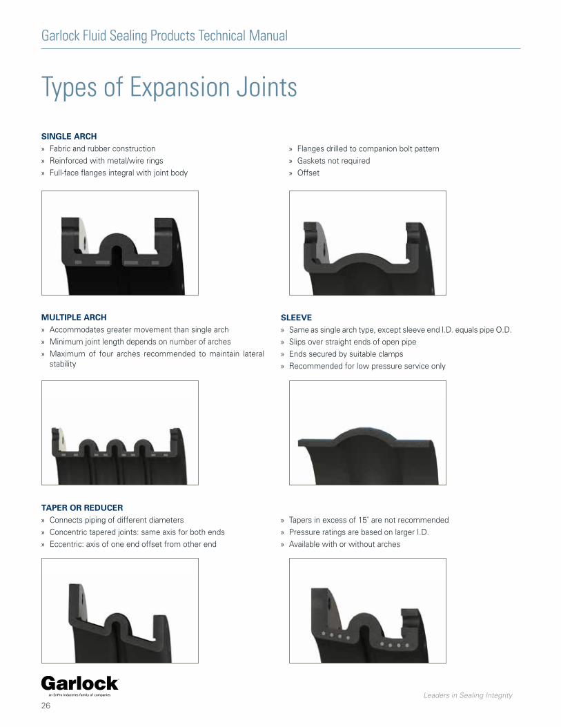
Types of Expansion Joints
SINGLE ARCH » Fabric and rubber construction
» Reinforced with metal/wire rings
» Full-face flanges integral with joint body
MULTIPLE ARCH » Accommodates greater movement than single arch
» Minimum joint length depends on number of arches
» Maximum of four arches recommended to maintain lateral stability
SLEEVE » Same as single arch type, except sleeve end I.D. equals pipe O.D.
» Slips over straight ends of open pipe
» Ends secured by suitable clamps
» Recommended for low pressure service only
TAPER OR REDUCER » Connects piping of different diameters
» Concentric tapered joints: same axis for both ends
» Eccentric: axis of one end offset from other end
» Tapers in excess of 15˚ are not recommended
» Pressure ratings are based on larger I.D.
» Available with or without arches
» Flanges drilled to companion bolt pattern
» Gaskets not required
» Offset
Garlock Fluid Sealing Products Technical Manual
Leaders in Sealing Integrity
27
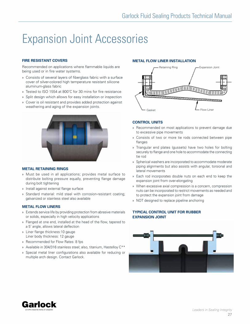
Expansion Joint Accessories
FIRE RESISTANT COVERS
Recommended on applications where flammable liquids are being used or in fire water systems.
» Consists of several layers of fiberglass fabric with a surface cover of silver-colored high temperature resistant silicone aluminum-glass fabric
» Tested to ISO 1554 at 800˚C for 30 mins for fire resistance
» Split design which allows for easy installation or inspection
» Cover is oil resistant and provides added protection against weathering and aging of the expansion joints.
METAL RETAINING RINGS » Must be used in all applications; provides metal surface to
distribute bolting pressure equally, preventing flange damage during bolt tightening
» Install against external flange surface
» Standard material: mild steel with corrosion-resistant coating; galvanized or stainless steel also available
METAL FLOW LINERS » Extends service life by providing protection from abrasive materials
or solids, especially in high velocity applications
» Flanged at one end, installed at the head of the flow, tapered to a 5˚ angle, allows lateral deflection
» Liner flange thickness:10 gauge Liner body thickness: 12 gauge
» Recommended for Flow Rates: 8 fps
» Available in 304/316 stainless steel; also, titanium, Hastelloy C**
» Special metal liner configurations also available for reducing or multiple arch design. Contact Garlock.
Retaining Ring Expansion Joint
Gasket Flow Liner
METAL FLOW LINER INSTALLATION
CONTROL UNITS » Recommended on most applications to prevent damage due
to excessive pipe movements
» Consists of two or more tie rods connected between pipe flanges
» Triangular end plates (gussets) have two holes for bolting securely to flange and one hole to accommodate the connecting tie rod
» Spherical washers are incorporated to accommodate moderate piping alignments but also assists with angular, torsional and lateral movements
» Each rod incorporates double nuts on each end to keep the expansion joint from over-elongating
» When excessive axial compression is a concern, compression nuts can be incorporated to restrict movements as needed and to protect the expansion joint from damage
» NOT designed to replace pipeline anchoring
TYPICAL CONTROL UNIT FOR RUBBER EXPANSION JOINT
Garlock Fluid Sealing Products Technical Manual
Leaders in Sealing Integrity
28
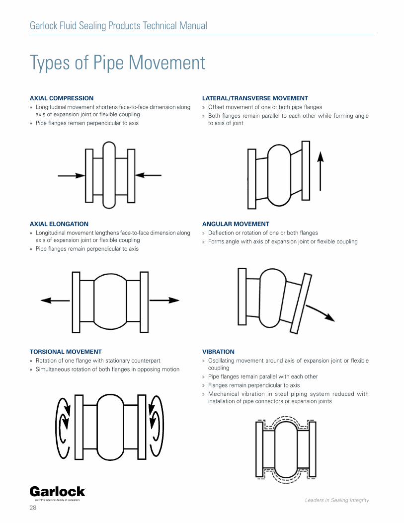
Types of Pipe Movement
AXIAL COMPRESSION » Longitudinal movement shortens face-to-face dimension along
axis of expansion joint or flexible coupling
» Pipe flanges remain perpendicular to axis
AXIAL ELONGATION » Longitudinal movement lengthens face-to-face dimension along
axis of expansion joint or flexible coupling
» Pipe flanges remain perpendicular to axis
TORSIONAL MOVEMENT » Rotation of one flange with stationary counterpart
» Simultaneous rotation of both flanges in opposing motion
LATERAL/TRANSVERSE MOVEMENT » Offset movement of one or both pipe flanges
» Both flanges remain parallel to each other while forming angle to axis of joint
ANGULAR MOVEMENT » Deflection or rotation of one or both flanges
» Forms angle with axis of expansion joint or flexible coupling
VIBRATION » Oscillating movement around axis of expansion joint or flexible
coupling
» Pipe flanges remain parallel with each other
» Flanges remain perpendicular to axis
» Mechanical vibration in steel piping system reduced with installation of pipe connectors or expansion joints
Garlock Fluid Sealing Products Technical Manual
Leaders in Sealing Integrity
29
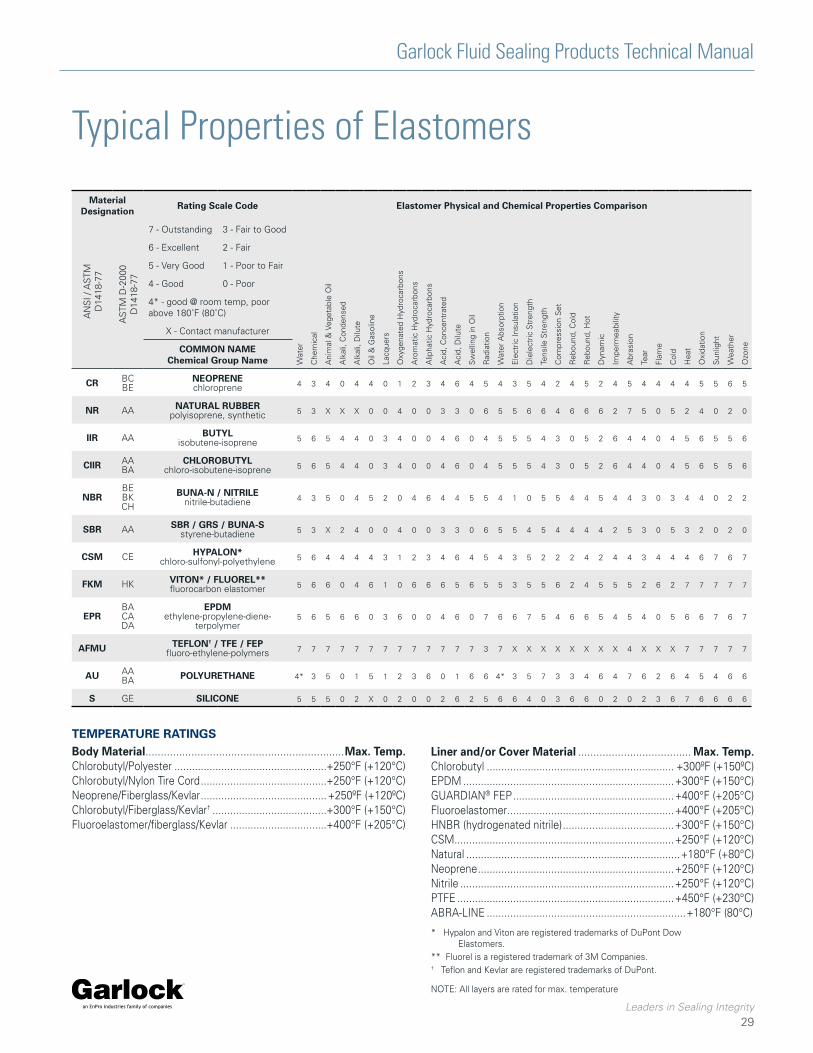
Typical Properties of Elastomers
Material Designation Rating Scale Code Elastomer Physical and Chemical Properties Comparison
AN
SI /
AS
TMD
1418
-77
AS
TM D
-200
0D
1418
-77
7 - Outstanding 3 - Fair to Good
Wat
er
Che
mic
al
Ani
mal
& V
eget
able
Oil
Alk
ali,
Con
dens
ed
Alk
ali,
Dilu
te
Oil
& G
asol
ine
Lacq
uers
Oxy
gena
ted
Hyd
roca
rbon
s
Aro
mat
ic H
ydro
carb
ons
Alip
hatic
Hyd
roca
rbon
s
Aci
d, C
once
ntra
ted
Aci
d, D
ilute
Sw
ellin
g in
Oil
Rad
iatio
n
Wat
er A
bsor
ptio
n
Ele
ctric
Insu
latio
n
Die
lect
ric S
tren
gth
Tens
ile S
tren
gth
Com
pres
sion
Set
Reb
ound
, Col
d
Reb
ound
, Hot
Dyn
amic
Impe
rmea
bilit
y
Abr
asio
n
Tear
Flam
e
Col
d
Hea
t
Oxi
datio
n
Sun
light
Wea
ther
Ozo
ne
6 - Excellent 2 - Fair
5 - Very Good 1 - Poor to Fair
4 - Good 0 - Poor
4* - good @ room temp, poor above 180˚F (80˚C)
X - Contact manufacturer
COMMON NAMEChemical Group Name
CR BCBE
NEOPRENEchloroprene 4 3 4 0 4 4 0 1 2 3 4 6 4 5 4 3 5 4 2 4 5 2 4 5 4 4 4 4 5 5 6 5
NR AA NATURAL RUBBERpolyisoprene, synthetic 5 3 X X X 0 0 4 0 0 3 3 0 6 5 5 6 6 4 6 6 6 2 7 5 0 5 2 4 0 2 0
IIR AA BUTYLisobutene-isoprene 5 6 5 4 4 0 3 4 0 0 4 6 0 4 5 5 5 4 3 0 5 2 6 4 4 0 4 5 6 5 5 6
CIIR AABA
CHLOROBUTYLchloro-isobutene-isoprene 5 6 5 4 4 0 3 4 0 0 4 6 0 4 5 5 5 4 3 0 5 2 6 4 4 0 4 5 6 5 5 6
NBRBEBKCH
BUNA-N / NITRILEnitrile-butadiene 4 3 5 0 4 5 2 0 4 6 4 4 5 5 4 1 0 5 5 4 4 5 4 4 3 0 3 4 4 0 2 2
SBR AA SBR / GRS / BUNA-Sstyrene-butadiene 5 3 X 2 4 0 0 4 0 0 3 3 0 6 5 5 4 5 4 4 4 4 2 5 3 0 5 3 2 0 2 0
CSM CE HYPALON*chloro-sulfonyl-polyethylene 5 6 4 4 4 4 3 1 2 3 4 6 4 5 4 3 5 2 2 2 4 2 4 4 3 4 4 4 6 7 6 7
FKM HK VITON* / FLUOREL**fluorocarbon elastomer 5 6 6 0 4 6 1 0 6 6 6 5 6 5 5 3 5 5 6 2 4 5 5 5 2 6 2 7 7 7 7 7
EPRBACADA
EPDMethylene-propylene-diene-
terpolymer5 6 5 6 6 0 3 6 0 0 4 6 0 7 6 6 7 5 4 6 6 5 4 5 4 0 5 6 6 7 6 7
AFMU TEFLON† / TFE / FEPfluoro-ethylene-polymers 7 7 7 7 7 7 7 7 7 7 7 7 7 3 7 X X X X X X X X 4 X X X 7 7 7 7 7
AU AABA POLYURETHANE 4* 3 5 0 1 5 1 2 3 6 0 1 6 6 4* 3 5 7 3 3 4 6 4 7 6 2 6 4 5 4 6 6
S GE SILICONE 5 5 5 0 2 X 0 2 0 0 2 6 2 5 6 6 4 0 3 6 6 0 2 0 2 3 6 7 6 6 6 6
* Hypalon and Viton are registered trademarks of DuPont Dow Elastomers.
** Fluorel is a registered trademark of 3M Companies.† Teflon and Kevlar are registered trademarks of DuPont.
TEMPERATURE RATINGSBody Material .................................................................Max. Temp. Chlorobutyl/Polyester ....................................................+250°F (+120°C)Chlorobutyl/Nylon Tire Cord ...........................................+250°F (+120°C)Neoprene/Fiberglass/Kevlar ...........................................+250ºF (+120ºC)Chlorobutyl/Fiberglass/Kevlar† .......................................+300°F (+150°C)Fluoroelastomer/fiberglass/Kevlar .................................+400°F (+205°C)
NOTE: All layers are rated for max. temperature
Liner and/or Cover Material ..................................... Max. Temp. Chlorobutyl ................................................................ +300ºF (+150ºC) EPDM ........................................................................+300°F (+150°C)GUARDIAN® FEP .......................................................+400°F (+205°C)Fluoroelastomer .........................................................+400°F (+205°C)HNBR (hydrogenated nitrile) ......................................+300°F (+150°C) CSM ...........................................................................+250°F (+120°C) Natural .........................................................................+180°F (+80°C) Neoprene ...................................................................+250°F (+120°C) Nitrile .........................................................................+250°F (+120°C) PTFE ..........................................................................+450°F (+230°C)ABRA-LINE ....................................................................+180°F (80°C)
Garlock Fluid Sealing Products Technical Manual
Leaders in Sealing Integrity
30
Expansion Joint Installation
PREPARATION
Check service range » Double check performance limits against anticipated operating
conditions
» Check temperature, pressure, vacuum recommendations
» Check total joint deflection—alter as needed to reduce deflection to correct range
» Anchor lines
Check location » Proper location is usually close to main anchoring point
» Install pipe guide(s) for proper alignment
» Joint should absorb pipeline expansion / contraction between fixed anchor points
Check cover » Check outside joint cover for damage
» Cover will keep harmful materials from penetrating joint carcass
Check alignment » Alignment should be 0.125" (3.2 mm) or less
» If 0.125" (3.2mm) must be exceeded, use a special offset joint
Check support » Weight must not be carried by joint
» Support with hangers or anchors
Check flanges » Clean all mating flanges
» Do not gouge or mutilate surfaces during cleaning
» Carefully examine used parts for smoothness
INSTALLATION
Apply lubricant » On elastomeric joints only, not required with all PTFE- or FEP-
lined joints
» Coat rubber faces with graphite in water, or glycerine, to prevent joint adherence to pipe flanges
Insert bolts from arch side » On elastomeric joints only, not necessary with PTFE joints/
couplings with threaded holes
» Set bolt heads adjacent to arch
Tighten bolts » Elastomeric joints only, tighten gradually and equally, alternating
around flange
» Edges of joint must bulge slightly at flange O.D.
Check tightness » Within one week after application, then periodically
» In hot or cold water systems during cyclical changes
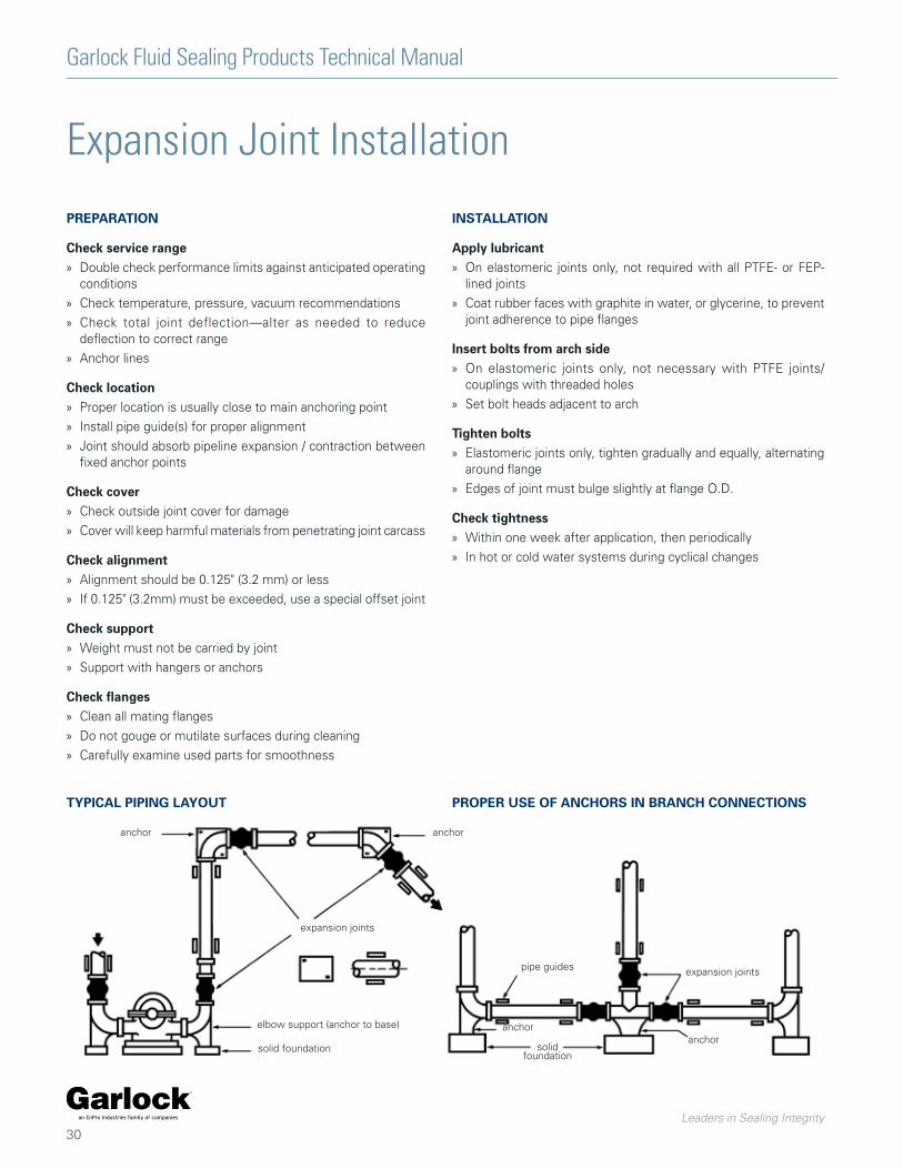
TYPICAL PIPING LAYOUT PROPER USE OF ANCHORS IN BRANCH CONNECTIONS
anchor anchor
expansion joints
elbow support (anchor to base)
solid foundation
pipe guides
anchor
solidfoundation
anchor
expansion joints

Garlock Fluid Sealing Products Technical Manual
Leaders in Sealing Integrity
31
Troubleshooting
General Precautions
FLANGE LEAKAGE » Check bolt tightness
» Check mating flange surface area for:
› Grooves
› Scratches
› Distorted areas
» Over-extension may indicate need for control units
LIQUID WEEPING FROM BOLT HOLES » Check tube portion of joint for leaks; replace if necessary
CRACKING AT BASE OF ARCH OR FLANGE » Check installed face-to-face dimensions for over-extension or
over-compression
» Check for proper pipe alignment: must not exceed 0.125" (3.2mm)
EXCESSIVE BALLOONING OF ARCH » Indicates distortion/deterioration of joint strengthening
members, or excessive system pressure
» Re-evaluate service conditions
» Install new joint
ELASTOMERIC JOINTS ONLY » Use proper care breaking seal
» Drive flanges apart gently with wooden wedges
» Bring insulation only to pipe flange—do not insulate over or around joint
› Covering joints may make leak detection difficult
› Insulation could restrict joint movement or cause overheating
» Store in cool, dry, dark area
» Do not rest on flange edges
» Carefully protect joints near welding operations
» Never install spool-type joints next to flangeless check valves or butterfly valves
» Install only against full-face metal flanges or damage/leakage could result; restrictions also apply to raised face or any non-full face flange
WARNING:Properties/applications shown throughout this brochure are typical. Your specific application should not be undertaken without independent study and evaluation for suitability. For specific application recommendations consult Garlock. Failure to select the proper sealing products could result in property damage and/or serious personal injury.
Performance data published in this brochure has been developed from field testing, customer field reports and/or in-house testing.
While the utmost care has been used in compiling this brochure, we assume no responsibility for errors. Specifications subject to change without notice. This edition cancels all previous issues. Subject to change without notice.
GARLOCK is a registered trademark for packings, seals, gaskets, and other products of Garlock.
Garlock Fluid Sealing Products Technical Manual
Leaders in Sealing Integrity
32
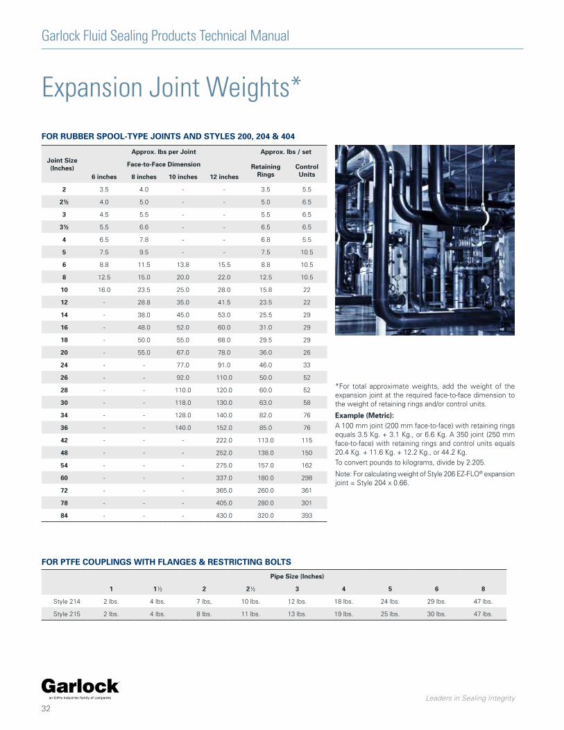
Expansion Joint Weights*
Joint Size(Inches)
Approx. lbs per Joint Approx. lbs / set
Face-to-Face Dimension Retaining Rings
Control Units6 inches 8 inches 10 inches 12 inches
2 3.5 4.0 - - 3.5 5.5
2½ 4.0 5.0 - - 5.0 6.5
3 4.5 5.5 - - 5.5 6.5
3½ 5.5 6.6 - - 6.5 6.5
4 6.5 7.8 - - 6.8 5.5
5 7.5 9.5 - - 7.5 10.5
6 8.8 11.5 13.8 15.5 8.8 10.5
8 12.5 15.0 20.0 22.0 12.5 10.5
10 16.0 23.5 25.0 28.0 15.8 22
12 - 28.8 35.0 41.5 23.5 22
14 - 38.0 45.0 53.0 25.5 29
16 - 48.0 52.0 60.0 31.0 29
18 - 50.0 55.0 68.0 29.5 29
20 - 55.0 67.0 78.0 36.0 26
24 - - 77.0 91.0 46.0 33
26 - - 92.0 110.0 50.0 52
28 - - 110.0 120.0 60.0 52
30 - - 118.0 130.0 63.0 58
34 - - 128.0 140.0 82.0 76
36 - - 140.0 152.0 85.0 76
42 - - - 222.0 113.0 115
48 - - - 252.0 138.0 150
54 - - - 275.0 157.0 162
60 - - - 337.0 180.0 298
72 - - - 365.0 260.0 361
78 - - - 405.0 280.0 301
84 - - - 430.0 320.0 393
FOR RUBBER SPOOL-TYPE JOINTS AND STYLES 200, 204 & 404
*For total approximate weights, add the weight of the expansion joint at the required face-to-face dimension to the weight of retaining rings and/or control units.
Example (Metric):A 100 mm joint (200 mm face-to-face) with retaining rings equals 3.5 Kg. + 3.1 Kg., or 6.6 Kg. A 350 joint (250 mm face-to-face) with retaining rings and control units equals 20.4 Kg. + 11.6 Kg. + 12.2 Kg., or 44.2 Kg.To convert pounds to kilograms, divide by 2.205.
Note: For calculating weight of Style 206 EZ-FLO® expansion joint = Style 204 x 0.66.
Pipe Size (Inches)
1 1½ 2 2½ 3 4 5 6 8
Style 214 2 lbs. 4 lbs. 7 lbs, 10 lbs. 12 lbs. 18 lbs. 24 lbs. 29 lbs. 47 lbs.
Style 215 2 lbs. 4 lbs. 8 lbs. 11 lbs. 13 lbs. 19 lbs. 25 lbs. 30 lbs. 47 lbs.
FOR PTFE COUPLINGS WITH FLANGES & RESTRICTING BOLTS
Garlock Fluid Sealing Products Technical Manual
Leaders in Sealing Integrity
33
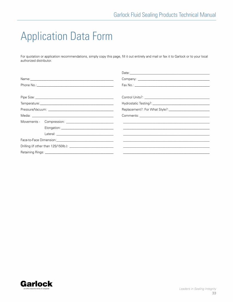
Application Data Form
For quotation or application recommendations, simply copy this page, fill it out entirely and mail or fax it to Garlock or to your local authorized distributor.
Date: _________________________________________________
Name: ___________________________________________________ Company: ____________________________________________
Phone No.: _______________________________________________ Fax No.: ______________________________________________
Pipe Size: ________________________________________________ Control Units?: ________________________________________
Temperature: _____________________________________________ Hydrostatic Testing?: ___________________________________
Pressure/Vacuum: ________________________________________ Replacement?: For What Style?: _________________________
Media: __________________________________________________ Comments: ___________________________________________
Movements - Compression: _____________________________ _____________________________________________________
Elongation: ________________________________ _____________________________________________________
Lateral: ___________________________________ _____________________________________________________
Face-to-Face Dimension:___________________________________ _____________________________________________________
Drilling (if other than 125/150Ib.): ___________________________ _____________________________________________________
Retaining Rings: __________________________________________ _____________________________________________________
Garlock Fluid Sealing Products Technical Manual
Leaders in Sealing Integrity
34
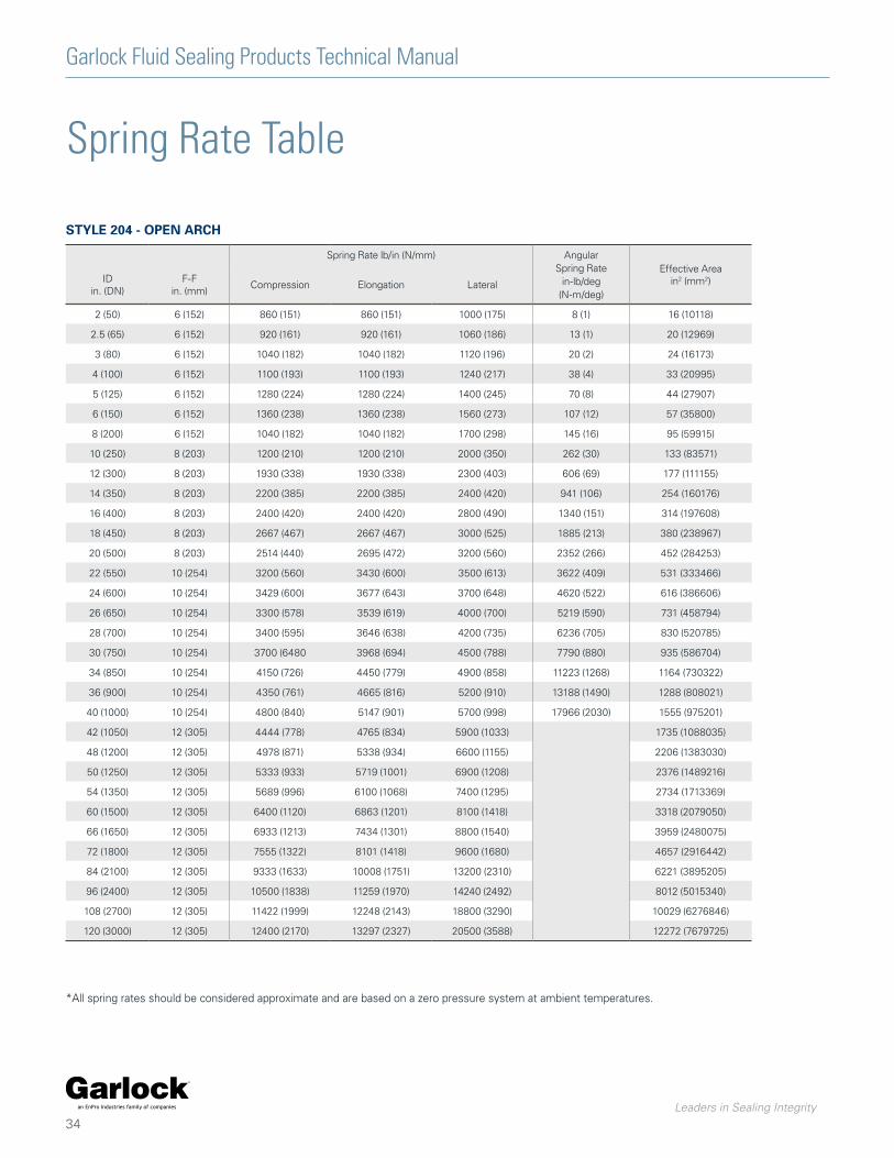
Spring Rate lb/in (N/mm) Angular Spring Rate
in-lb/deg(N-m/deg)
Effective Area in2 (mm2)ID
in. (DN)F-F
in. (mm)Compression Elongation Lateral
2 (50) 6 (152) 860 (151) 860 (151) 1000 (175) 8 (1) 16 (10118)
2.5 (65) 6 (152) 920 (161) 920 (161) 1060 (186) 13 (1) 20 (12969)
3 (80) 6 (152) 1040 (182) 1040 (182) 1120 (196) 20 (2) 24 (16173)
4 (100) 6 (152) 1100 (193) 1100 (193) 1240 (217) 38 (4) 33 (20995)
5 (125) 6 (152) 1280 (224) 1280 (224) 1400 (245) 70 (8) 44 (27907)
6 (150) 6 (152) 1360 (238) 1360 (238) 1560 (273) 107 (12) 57 (35800)
8 (200) 6 (152) 1040 (182) 1040 (182) 1700 (298) 145 (16) 95 (59915)
10 (250) 8 (203) 1200 (210) 1200 (210) 2000 (350) 262 (30) 133 (83571)
12 (300) 8 (203) 1930 (338) 1930 (338) 2300 (403) 606 (69) 177 (111155)
14 (350) 8 (203) 2200 (385) 2200 (385) 2400 (420) 941 (106) 254 (160176)
16 (400) 8 (203) 2400 (420) 2400 (420) 2800 (490) 1340 (151) 314 (197608)
18 (450) 8 (203) 2667 (467) 2667 (467) 3000 (525) 1885 (213) 380 (238967)
20 (500) 8 (203) 2514 (440) 2695 (472) 3200 (560) 2352 (266) 452 (284253)
22 (550) 10 (254) 3200 (560) 3430 (600) 3500 (613) 3622 (409) 531 (333466)
24 (600) 10 (254) 3429 (600) 3677 (643) 3700 (648) 4620 (522) 616 (386606)
26 (650) 10 (254) 3300 (578) 3539 (619) 4000 (700) 5219 (590) 731 (458794)
28 (700) 10 (254) 3400 (595) 3646 (638) 4200 (735) 6236 (705) 830 (520785)
30 (750) 10 (254) 3700 (6480 3968 (694) 4500 (788) 7790 (880) 935 (586704)
34 (850) 10 (254) 4150 (726) 4450 (779) 4900 (858) 11223 (1268) 1164 (730322)
36 (900) 10 (254) 4350 (761) 4665 (816) 5200 (910) 13188 (1490) 1288 (808021)
40 (1000) 10 (254) 4800 (840) 5147 (901) 5700 (998) 17966 (2030) 1555 (975201)
42 (1050) 12 (305) 4444 (778) 4765 (834) 5900 (1033) 1735 (1088035)
48 (1200) 12 (305) 4978 (871) 5338 (934) 6600 (1155) 2206 (1383030)
50 (1250) 12 (305) 5333 (933) 5719 (1001) 6900 (1208) 2376 (1489216)
54 (1350) 12 (305) 5689 (996) 6100 (1068) 7400 (1295) 2734 (1713369)
60 (1500) 12 (305) 6400 (1120) 6863 (1201) 8100 (1418) 3318 (2079050)
66 (1650) 12 (305) 6933 (1213) 7434 (1301) 8800 (1540) 3959 (2480075)
72 (1800) 12 (305) 7555 (1322) 8101 (1418) 9600 (1680) 4657 (2916442)
84 (2100) 12 (305) 9333 (1633) 10008 (1751) 13200 (2310) 6221 (3895205)
96 (2400) 12 (305) 10500 (1838) 11259 (1970) 14240 (2492) 8012 (5015340)
108 (2700) 12 (305) 11422 (1999) 12248 (2143) 18800 (3290) 10029 (6276846)
120 (3000) 12 (305) 12400 (2170) 13297 (2327) 20500 (3588) 12272 (7679725)
Spring Rate Table
*All spring rates should be considered approximate and are based on a zero pressure system at ambient temperatures.
STYLE 204 - OPEN ARCH
Garlock Fluid Sealing Products Technical Manual
Leaders in Sealing Integrity
35
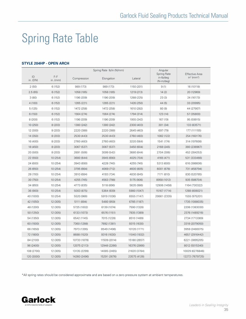
Spring Rate Table
*All spring rates should be considered approximate and are based on a zero pressure system at ambient temperatures.
Spring Rate lb/in (N/mm) Angular Spring Rate
in-lb/deg(N-m/deg)
Effective Area in2 (mm2)ID
in. (DN)F-F
in. (mm)Compression Elongation Lateral
2 (50) 6 (152) 989 (173) 989 (173) 1150 (201) 9 (1) 16 (10118)
2.5 (65) 6 (152) 1058 (185) 1058 (185) 1219 (213) 14 (2) 20 (12969)
3 (80) 6 (152) 1196 (209) 1196 (209) 1288 (225) 23 (3) 24 (16173)
4 (100) 6 (152) 1265 (221) 1265 (221) 1426 (250) 44 (5) 33 (20995)
5 (125) 6 (152) 1472 (258) 1472 (258) 1610 (282) 80 (9) 44 (27907)
6 (150) 6 (152) 1564 (274) 1564 (274) 1794 (314) 123 (14) 57 (35800)
8 (200) 6 (152) 1196 (209) 1196 (209) 1955 (342) 167 (19) 95 (59915)
10 (250) 8 (203) 1380 (242) 1380 (242) 2300 (403) 301 (34) 133 (83571)
12 (300) 8 (203) 2220 (388) 2220 (388) 2645 (463) 697 (79) 177 (111155)
14 (350) 8 (203) 2530 (443) 2530 (443) 2760 (483) 1082 (122) 254 (160176)
16 (400) 8 (203) 2760 (483) 2760 (483) 3220 (564) 1541 (174) 314 (197608)
18 (450) 8 (203) 3067 (537) 3067 (537) 3450 (604) 2168 (245) 380 (238967)
20 (500) 8 (203) 2891 (506) 3099 (542) 3680 (644) 2704 (306) 452 (284253)
22 (550) 10 (254) 3680 (644) 3945 (690) 4025 (704) 4165 (471) 531 (333466)
24 (600) 10 (254) 3943 (690) 4228 (740) 4255 (745) 5313 (600) 616 (386606)
26 (650) 10 (254) 3795 (664) 4069 (712) 4600 (805) 6001 (678) 731 (458794)
28 (700) 10 (254) 3910 (684) 4193 (734) 4830 (845) 7171 (810) 830 (520785)
30 (750) 10 (254) 4255 (745) 4563 (798) 5175 (906) 8958 (1012) 935 (586704)
34 (850) 10 (254) 4773 (835) 5118 (896) 5635 (986) 12906 (1458) 1164 (730322)
36 (900) 10 (254) 5003 (875) 5364 (939) 5980 (1047) 15167 (1714) 1288 (808021)
40 (1000) 10 (254) 5520 (966) 5919 (1036) 6555 (1147) 20661 (2335) 1555 (975201)
42 (1050) 12 (305) 5111 (894) 5480 (959) 6785 (1187) 1735 (1088035)
48 (1200) 12 (305) 5725 (1002) 6139 (1074) 7590 (1328) 2206 (1383030)
50 (1250) 12 (305) 6133 (1073) 6576 (1151) 7935 (1389) 2376 (1489216)
54 (1350) 12 (305) 6542 (1145) 7015 (1228) 8510 (1489) 2734 (1713369)
60 (1500) 12 (305) 7360 (1288) 7892 (1381) 9315 (1630) 3318 (2079050)
66 (1650) 12 (305) 7973 (1395) 8549 (1496) 10120 (1771) 3959 (2480075)
72 (1800) 12 (305) 8688 (1520) 9316 (1630) 11040 (1932) 4657 (2916442)
84 (2100) 12 (305) 10733 (1878) 11509 (2014) 15180 (2657) 6221 (3895205)
96 (2400) 12 (305) 12075 (2113) 12948 (2266) 16376 (2866) 8012 (5015340)
108 (2700) 12 (305) 13135 (2299) 14085 (2465) 21620 (3784) 10029 (6276846)
120 (3000) 12 (305) 14260 (2496) 15291 (2676) 23575 (4126) 12272 (7679725)
STYLE 204HP - OPEN ARCH
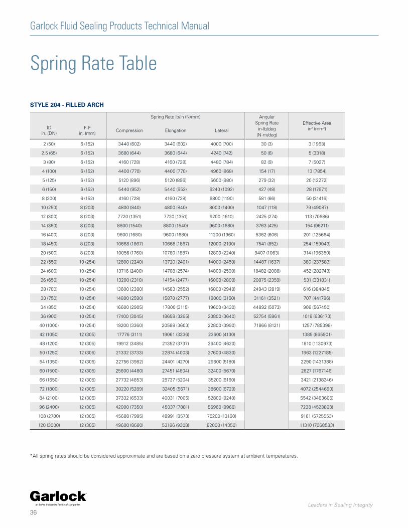
Garlock Fluid Sealing Products Technical Manual
Leaders in Sealing Integrity
36
Spring Rate Table
*All spring rates should be considered approximate and are based on a zero pressure system at ambient temperatures.
Spring Rate lb/in (N/mm) Angular Spring Rate
in-lb/deg(N-m/deg)
Effective Area in2 (mm2)ID
in. (DN)F-F
in. (mm)Compression Elongation Lateral
2 (50) 6 (152) 3440 (602) 3440 (602) 4000 (700) 30 (3) 3 (1963)
2.5 (65) 6 (152) 3680 (644) 3680 (644) 4240 (742) 50 (6) 5 (3318)
3 (80) 6 (152) 4160 (728) 4160 (728) 4480 (784) 82 (9) 7 (5027)
4 (100) 6 (152) 4400 (770) 4400 (770) 4960 (868) 154 (17) 13 (7854)
5 (125) 6 (152) 5120 (896) 5120 (896) 5600 (980) 279 (32) 20 (12272)
6 (150) 6 (152) 5440 (952) 5440 (952) 6240 (1092) 427 (48) 28 (17671)
8 (200) 6 (152) 4160 (728) 4160 (728) 6800 (1190) 581 (66) 50 (31416)
10 (250) 8 (203) 4800 (840) 4800 (840) 8000 (1400) 1047 (118) 79 (49087)
12 (300) 8 (203) 7720 (1351) 7720 (1351) 9200 (1610) 2425 (274) 113 (70686)
14 (350) 8 (203) 8800 (1540) 8800 (1540) 9600 (1680) 3763 (425) 154 (96211)
16 (400) 8 (203) 9600 (1680) 9600 (1680) 11200 (1960) 5362 (606) 201 (125664)
18 (450) 8 (203) 10668 (1867) 10668 (1867) 12000 (2100) 7541 (852) 254 (159043)
20 (500) 8 (203) 10056 (1760) 10780 (1887) 12800 (2240) 9407 (1063) 314 (196350)
22 (550) 10 (254) 12800 (2240) 13720 (2401) 14000 (2450) 14487 (1637) 380 (237583)
24 (600) 10 (254) 13716 (2400) 14708 (2574) 14800 (2590) 18482 (2088) 452 (282743)
26 (650) 10 (254) 13200 (2310) 14154 (2477) 16000 (2800) 20875 (2359) 531 (331831)
28 (700) 10 (254) 13600 (2380) 14583 (2552) 16800 (2940) 24943 (2819) 616 (384845)
30 (750) 10 (254) 14800 (2590) 15870 (2777) 18000 (3150) 31161 (3521) 707 (441786)
34 (850) 10 (254) 16600 (2905) 17800 (3115) 19600 (3430) 44892 (5073) 908 (567450)
36 (900) 10 (254) 17400 (3045) 18658 (3265) 20800 (3640) 52754 (5961) 1018 (636173)
40 (1000) 10 (254) 19200 (3360) 20588 (3603) 22800 (3990) 71866 (8121) 1257 (785398)
42 (1050) 12 (305) 17776 (3111) 19061 (3336) 23600 (4130) 1385 (865901)
48 (1200) 12 (305) 19912 (3485) 21352 (3737) 26400 (4620) 1810 (1130973)
50 (1250) 12 (305) 21332 (3733) 22874 (4003) 27600 (4830) 1963 (1227185)
54 (1350) 12 (305) 22756 (3982) 24401 (4270) 29600 (5180) 2290 (1431388)
60 (1500) 12 (305) 25600 (4480) 27451 (4804) 32400 (5670) 2827 (1767146)
66 (1650) 12 (305) 27732 (4853) 29737 (5204) 35200 (6160) 3421 (2138246)
72 (1800) 12 (305) 30220 (5289) 32405 (5671) 38600 (6720) 4072 (2544690)
84 (2100) 12 (305) 37332 (6533) 40031 (7005) 52800 (9240) 5542 (3463606)
96 (2400) 12 (305) 42000 (7350) 45037 (7881) 56960 (9968) 7238 (4523893)
108 (2700) 12 (305) 45688 (7995) 48991 (8573) 75200 (13160) 9161 (5725553)
120 (3000) 12 (305) 49600 (8680) 53186 (9308) 82000 (14350) 11310 (7068583)
STYLE 204 - FILLED ARCH
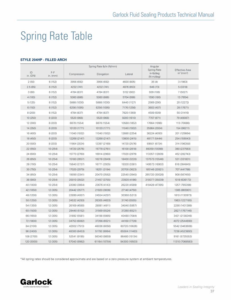
Garlock Fluid Sealing Products Technical Manual
Leaders in Sealing Integrity
37
Spring Rate lb/in (N/mm) Angular Spring Rate
in-lb/deg(N-m/deg)
Effective Area in2 (mm2)ID
in. (DN)F-F
in. (mm)Compression Elongation Lateral
2 (50) 6 (152) 3956 (692) 3956 (692) 4600 (805) 35 (4) 3 (1963)
2.5 (65) 6 (152) 4232 (741) 4232 (741) 4876 (853) 646 (73) 5 (3318)
3 (80) 6 (152) 4784 (837) 4784 (837) 5152 (902) 939 (106) 7 (5027)
4 (100) 6 (152) 5060 (886) 5060 (886) 5704 (998) 1590 (180) 13 (7854)
5 (125) 6 (152) 5888 (1030) 5888 (1030) 6440 (1127) 2569 (290) 20 (12272)
6 (150) 6 (152) 6256 (1095) 6256 (1095) 7176 (1256) 3603 (407) 28 (17671)
8 (200) 6 (152) 4784 (837) 4784 (837) 7820 (1369) 4509 (509) 50 (31416)
10 (250) 8 (203) 5520 (966) 5520 (966) 9200 (1610) 7707 (871) 79 (49087)
12 (300) 8 (203) 8878 (1554) 8878 (1554) 10580 (1852) 17664 (1996) 113 (70686)
14 (350) 8 (203) 10120 (1771) 10120 (1771) 11040 (1932) 25964 (2934) 154 (96211)
16 (400) 8 (203) 11040 (1932) 11040 (1932) 12880 (2254) 36224 (4093) 201 (125664)
18 (450) 8 (203) 12268 (2147) 12268 (2147) 13800 (2415) 48177 (5444) 254 (159043)
20 (500) 8 (203) 11564 (2024) 12397 (2169) 14720 (2576) 59501 (6724) 314 (196350)
22 (550) 10 (254) 14720 (2576) 15778 (2761) 16100 (2818) 89359 (10098) 380 (237583)
24 (600) 10 (254) 15773 (2760) 16914 (2960) 17020 (2979) 113357 (12809) 452 (282743)
26 (650) 10 (254) 15180 (2657) 16278 (2849) 18400 (3220) 137573 (15546) 531 (331831)
28 (700) 10 (254) 15640 (2737) 16771 (2935) 19320 (3381) 149573 (16902) 616 (384845)
30 (750) 10 (254) 17020 (2979) 18251 (3194) 20700 (3623) 185146 (20921) 707 (441786)
34 (850) 10 (254) 19090 (3341) 20470 (3582) 22540 (3945) 265720 (30026) 908 (567450)
36 (900) 10 (254) 20010 (3502) 21457 (3755) 23920 (4186) 310077 (35039) 1018 (636173)
40 (1000) 10 (254) 22080 (3864) 23676 (4143) 26220 (4589) 419428 (47395) 1257 (785398)
42 (1050) 12 (305) 20442 (3577) 21920 (3836) 27140 (4750) 1385 (865901)
48 (1200) 12 (305) 22899 (4007) 24554 (4297) 30360 (5313) 1810 (1130973)
50 (1250) 12 (305) 24532 (4293) 26305 (4603) 31740 (5555) 1963 (1227185)
54 (1350) 12 (305) 26169 (4580) 28061 (4911) 34040 (5957) 2290 (1431388)
60 (1500) 12 (305) 29440 (5152) 31569 (5524) 37260 (6521) 2827 (1767146)
66 (1650) 12 (305) 31892 (5581) 34198 (5985) 40480 (7084) 3421 (2138246)
72 (1800) 12 (305) 34753 (6082) 37266 (6521) 44160 (7728) 4072 (2544690)
84 (2100) 12 (305) 42932 (7513) 46036 (8056) 60720 (10626) 5542 (3463606)
96 (2400) 12 (305) 48300 (8453) 51792 (9064) 65504 (11463) 7238 (4523893)
108 (2700) 12 (305) 52541 (9195) 56340 (9859) 86480 (15134) 9161 (5725553)
120 (3000) 12 (305) 57040 (9982) 61164 (10704) 94300 (16503) 11310 (7068583)
Spring Rate Table
*All spring rates should be considered approximate and are based on a zero pressure system at ambient temperatures.
STYLE 204HP - FILLED ARCH

Garlock Fluid Sealing Products Technical Manual
Leaders in Sealing Integrity
38
Spring Rate lb/in (N/mm) Angular Spring Rate
in-lb/deg(N-m/deg)
Effective Area in2 (mm2)ID
in. (DN)F-F
in. (mm)Compression Elongation Lateral
2 (50) 6 (152) 610 (107) 650 (114) 620 (109) 6 (1) 8 (5249)
2.5 (65) 6 (152) 630 (110) 665 (116) 615 (108) 9 (1) 11 (7352)
3 (80) 6 (152) 720 (126) 750 (131) 710 (124) 15 (2) 14 (9808)
4 (100) 6 (152) 765 (134) 870 (152) 825 (144) 30 (3) 22 (13633)
5 (125) 6 (152) 925 (162) 980 (172) 950 (166) 53 (6) 31 (19298)
6 (150) 6 (152) 1150 (201) 1265 (221) 1180 (207) 99 (11) 41 (25944)
8 (200) 6 (152) 1270 (222) 1380 (242) 1230 (215) 193 (22) 67 (42182)
10 (250) 8 (203) 1590 (278) 1725 (302) 1540 (270) 376 (43) 104 (65189)
12 (300) 8 (203) 1910 (334) 2070 (362) 1850 (324) 650 (73) 143 (89780)
14 (350) 8 (203) 1970 (345) 2050 (359) 1890 (331) 877 (99) 189 (118298)
16 (400) 8 (203) 2050 (359) 2160 (378) 1950 (341) 1206 (136) 241 (150743)
18 (450) 8 (203) 2150 (376) 2375 (416) 2210 (387) 1679 (190) 299 (187115)
20 (500) 8 (203) 2350 (411) 2470 (432) 2380 (417) 2155 (244) 363 (227413)
22 (550) 10 (254) 2550 (446) 2650 (464) 2575 (451) 2798 (316) 452 (283498)
24 (600) 10 (254) 2750 (481) 2830 (495) 2790 (488) 3556 (402) 531 (332648)
26 (650) 10 (254) 2900 (508) 3025 (529) 2980 (522) 4461 (504) 616 (385725)
28 (700) 10 (254) 3185 (557) 3275 (573) 3100 (543) 5601 (633) 707 (442729)
30 (750) 10 (254) 3200 (560) 3450 (604) 3120 (546) 6774 (765) 804 (503661)
34 (850) 10 (254) 3600 (630) 3845 (673) 3625 (634) 9697 (1096) 1018 (637304)
36 (900) 10 (254) 4250 (744) 4500 (788) 4300 (753) 12723 (1438) 1134 (710016)
40 (1000) 10 (254) 4380 (767) 4700 (823) 4565 (799) 16406 (1854) 1385 (867221)
42 (1050) 12 (305) 4550 (796) 4870 (852) 5050 (884) 18742 (2118) 1521 (951715)
48 (1200) 12 (305) 4870 (852) 5270 (922) 5930 (1038) 26490 (2993) 1963 (1228756)
50 (1250) 12 (305)
Contact Garlock for Engineering Evaluation
2124 (1328957)
54 (1350) 12 (305) 2463 (1541140)
60 (1500) 12 (305) 3019 (1888867)
66 (1650) 12 (305) 3632 (2271937)
72 (1800) 12 (305) 4301 (2690350)
84 (2100) 12 (305) 5809 (3633205)
96 (2400) 12 (305) 7543 (4717432)
108 (2700) 12 (305) 9503 (5943030)
120 (3000) 12 (305) 11690 (7310000)
STYLE 206 EZ-FLO® ARCH
Spring Rate Table
*All spring rates should be considered approximate and are based on a zero pressure system at ambient temperatures.
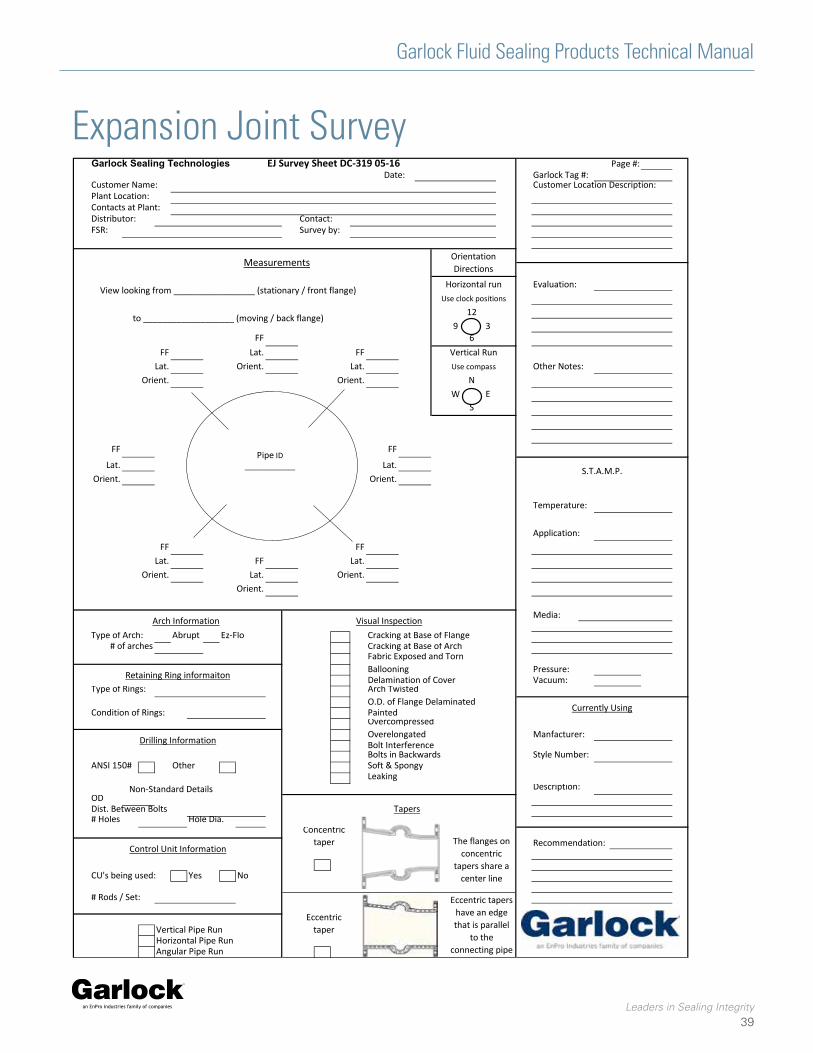
Garlock Fluid Sealing Products Technical Manual
Leaders in Sealing Integrity
39
Expansion Joint SurveyGarlock Sealing Technologies EJ Survey Sheet DC-319 05-16 Page #:
Date: Garlock Tag #:Customer Name: Customer Location Description:Plant Location:Contacts at Plant:Distributor: Contact:FSR: Survey by:
Evaluation:
129 3
FF 6FF Lat. FF
Lat. Orient. Lat. Other Notes:Orient. Orient. N
W ES
FF FF
Lat. Lat.Orient. Orient.
Temperature:
Application:FF FF
Lat. FF Lat.Orient. Lat. Orient.
Orient.
Media:
Type of Arch: Ez-Flo Cracking at Base of FlangeCracking at Base of ArchFabric Exposed and TornBallooning Pressure:Delamination of Cover Vacuum:
Type of Rings: Arch TwistedO.D. of Flange Delaminated
Condition of Rings: PaintedOvercompressedOverelongated Manfacturer:Bolt InterferenceBolts in Backwards Style Number:
ANSI 150# Other Soft & SpongyLeaking
Description:ODDist. Between Bolts# Holes Hole Dia.
CU's being used: Yes No
# Rods / Set:
Vertical Pipe RunHorizontal Pipe RunAngular Pipe Run
Retaining Ring informaiton
Arch Information
# of archesAbrupt
Control Unit Information
Drilling Information
Non-Standard Details
Tapers
Concentric taper
Eccentric taper
The flanges on concentric
tapers share a center line
Eccentric tapers have an edge that is parallel
to the connecting pipe
Recommendation:
Currently Using
Visual Inspection
Vertical Run
Use clock positions
Use compass
Measurements
S.T.A.M.P.
View looking from _________________ (stationary / front flange)
to ___________________ (moving / back flange)
Orientation Directions
Horizontal run
Pipe ID ____________

Tel: 1-877-GARLOCK / 315.597.4811 Fax: 800.543.0598 / 315.597.3216www.garlock.com
GARLOCKan EnPro Industries family of companies
GarlockGPTGarlock AustraliaGarlock de Canada, LTD
Garlock ChinaGarlock SingaporeGarlock GermanyGarlock India Private Limited
Garlock de Mexico, S.A. De C.V.Garlock New ZealandGarlock Great Britain LimitedGarlock Middle East
EJ 9-15_09.2016