g-fire catalog 2013 - grinnell.hu - grinnell hornyos ... · 56 valves valves model jpl 39109a...
TRANSCRIPT

53
VALVES

54
VALVES
www.tfppemea.com
Valves
Model JPL 39109S Butterfly Valves
Groove x Groove
Page – 55
Model JPL 39109A Butterfly Valves
Groove x Groove
Page – 55
Model BFV-N Butterfly Valves
Groove x Groove
Page – 57
Model TMRT
Resilient-Seated Gate Valves, OS&Y, Flange x Groove
Pages – 58, 59
Valves Pictorial Table of Contents
Model TMRG
Resilient-Seated Gate Valves, OS&Y, Groove x Groove
Pages – 58, 60
Model TMPT-P
Resilient-Seated Gate Valves, NRS, Flange x Groove
Pages – 61, 62
Model TMPG-P
Resilient-Seated Gate Valves, NRS, Groove x Groove
Pages – 61, 62
Model CV-1
Grooved Check Valves
Pages – 63 - 64
General notes: It is the Designer’s responsibility to select products suitable for the intended service and to ensure that pressure ratings and performance data is not exceeded. Always read and understand the installation constructions. Never remove any piping components nor correct or modify any piping deficiencies without first depressurizing and draining the system. Material should be verified to be compatible for the specific application.
Additional Valves Options AvailableContact TYCO for more information
Model TMPX
Model POST-IND
Model WALL-IND
Model TMRX
Model CV-1FR

Refer to back cover for country-specific contact information. 55
VALVES
Valves
Model JPL 39109S Butterfly Valves
Part Number Pipe Size Dimensions mm � � �
Approx. Weight
kg� � � �With Switch
Without Switch
Nominal mm� � � O.D.
mm� � � A B C E F G K M N P ∅V
39109SC060 39109S06050 60.3 100 77.5 81 130 208 111 75 60 75 227 150 8.4� � � � � � � � � � � � � � � � � � � � � � � � � � � � � � � � � � �
39109SC073 39109S07365 73.0 105 82 97 135 208 111 75 60 75 232 150 9.5� � � � � � � � � � � � � � � � � � � � � � � � � � � � � � � � � � � � � � � � �
39109SC076 39109S07665 76.1 105 82 97 135 208 111 75 60 75 232 150 9.5� � � � � � � � � � � � � � � � � � � � � � � � � � � � � � � � � � � � � � � � � � �
39109SC089 39109S08980 88.9 112 90 97 142 208 111 75 60 75 232 150 9.9� � � � � � � � � � � � � � � � � � � � � � � � � � � � � � � � � � � �
39109SC114 39109S114100 114.3 135 107 116 165 208 111 75 60 75 239 150 11.6� � � � � � � � � � � � � � � � � � � � � � � � � � � � � � � � � � � �
39109SC139 39109S139125 139.7 147 121 148 177 208 111 75 60 75 262 150 14.8 � � � � � � � � � � � � � � � � � � � � � � � � � � � � � � � � � � � � � � � � � �
39109SC141 39109S141125 141.3 147 121 148 177 208 111 75 60 75 262 150 14.8 � � � � � � � � � � � � � � � � � � � � � � � � � � � � � � � � � � � � �
39109SC165 39109S165150 165.1 180 150 148 210 215 111 75 60 75 274 225 18.2 � � � � � � � � � � � � � � � � � � � � � � � � � � � � � � � � � � � � � � � � � � � � �
39109SC168 39109S168150 168.3 180 150 148 210 215 111 75 60 75 274 225 18.2� � � � � � � � � � � � � � � � � � � � � � � � � � � � � � � � � � � � � � � � � �
39109SC219 39109S219200 219.1 204 172 133 234 215 111 75 60 75 274 225 20.5� � � � � � � � � � � � � � � � � � � � � � � � � � � � � � � � � � � � � � � � � � � �
39109SC273 39109S273250 273.1 250 233 159 301 276 179 138 104 132 307 300 46.3 � � � � � � � � � � � � � � � � � � � � � � � � � � � � � � � � � � � � � � � �
39109SC324 39109S324300 323.9 275 258 165 326 276 179 138 104 132 307 300 55.0 � � � � � � � � � � � � � � � � � � � � � � � � � � � � � � � � � � � � � � � � � � �
* = for valves without switch replace SC by S.
Note: recommended for mounting with GRINNELL G-FIRE Rigid couplings working temperature range is -15°C to 80°C (5°F to 176°F )
Option: Silicon free valves for automotive industry. Because of the special grease, the agency approvals do not apply.
SPECIFICATIONSMax Working Pressure
175 psi)Body
Bushing
Disc
Control Shaft & Spindle
Retainer Plug
O-Ring
Locking Ring
Performance
������ �� � � � � !
∅"
#
Issue 03, 04, 07
Cert No. 570, 669, 673
For detailed Listing and Approval
information see pages 101 - 108 or
contact Tyco Fire Protection Products.

56
VALVES
www.tfppemea.com
Valves
Model JPL 39109A Butterfly Valves
APSAD Approved
Part Number
Pipe Size Max Work
PressureBar$ � % Dimensions mm
� � �Approx. Weight
kg� � � �Nominal mm� � � O.D.
mm� � � A B C E F G K M N P ∅V
39109AC06050 60.3 16.0 100 77.5 81 130 208 111 75 60 75 226 150 8.4� � � � � � � � � � � � � � � � � � � � � � � � � � � � � � � � � � � � � �
39109AC07665 76.1 16.0 105 82 97 135 208 111 75 60 75 231 150 9.5� � � � � � � � � � � � � � � � � � � � � � � � � � � � � � � � � � � � � � � � � � � � � �
39109AC08980 88.9 16.0 112 90 97 142 208 111 75 60 75 238 150 9.9� � � � � � � � � � � � � � � � � � � � � � � � � � � � � � � � � � � � � � � �
39109AC114100 114.3 16.0 135 107 116 165 208 111 75 60 75 261 150 11.6� � � � � � � � � � � � � � � � � � � � � � � � � � � � � � � � � � � � � � � � �
39109AC139125 139.7 16.0 147 121 148 177 208 111 75 60 75 273 150 14.8 � � � � � � � � � � � � � � � � � � � � � � � � � � � � � � � � � � � � � � � � � � � � �
39109AC168150 168.3 16.0 180 150 148 210 215 111 75 60 75 306 225 18.2� � � � � � � � � � � � � � � � � � � � � � � � � � � � � � � � � � � � � � � � � � � � �
39109AC219200 219.1 16.0 204 172 133 234 215 111 75 60 75 330 225 20.5� � � � � � � � � � � � � � � � � � � � � � � � � � � � � � � � � � � � � � � � � � � � � �
39109AC273250 273.1 10.0 250 233 159 301 276 179 138 104 132 417 300 46.3 � � � � � � � � � � � � � � � � � � � � � � � � � � � � � � � � � � � � � � � � � �
39109AC324300 323.9 10.0 275 258 165 326 276 179 138 104 132 442 300 55.0 � � � � � � � � � � � � � � � � � � � � � � � � � � � � � � � � � � � � � � � � � � � � �
Note: recommended for mounting with GRINNELL G-FIRE Rigid couplings working temperature range is -18°C to 80°C (-0.4°F to 176°F )
SPECIFICATIONSBody
Bushing
Disc
Control Shaft & Spindle
Retainer Plug
O-Ring
Locking Ring
Performance
&'() * *+,- ./ 0 1 2 3 4 5
∅6
7
Refer to back cover for country-specific contact information. 57
VALVES
Valves
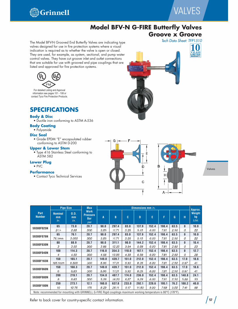
Model BFV-N G-FIRE Butterfly Valves Groove x Groove
Tech Data Sheet: TFP1510
Part Number
Pipe Size Max Work
PressureBar$ � % Dimensions mm
� � �Approx. Weight
kg� � � �Nominal mm� � � O.D.
mm� � � A B C D E F G H
59300F025N65 73.0 20.7 98.0 297.4 83.0 137.9 152.4 198.4 63.5 0 10.0� � � � � � � � � � � � � � � � � � � � � � � � � � � � � � � � � � �
59300F076N65 76.1 20.7 98.0 297.4 83.0 137.9 152.4 198.4 63.5 0 10.0� � � � � � � � � � � � � � � � � � � � � � � � � � � � � � � � � � � � �
59300F030N80 88.9 20.7 98.0 311.1 90.0 144.2 152.4 198.4 63.5 0 10.4� � � � � � � � � � � � � � � � � � � � � � � � � � � � � � � �
59300F040N100 114.3 20.7 116.0 354.3 110.0 167.1 152.4 198.4 63.5 0 12.7� � � � � � � � � � � � � � � � � � � � � � � � � � � � � � �
59300F165N150 165.1 20.7 149.0 439.7 151.0 212.0 152.4 198.4 63.5 17.0 18.6 � � � � � � � � � � � � � � � � � � � � � � � � � � � � � � � � � � � � �
59300F060N150 168.3 20.7 149.0 439.7 151.0 212.0 152.4 198.4 63.5 17.0 18.6� � � � � � � � � � � � � � � � � � � � � � � � � � � � � � � � � �
59300F080N200 219.1 20.7 134.0 487.7 174.0 236.0 152.4 198.4 63.5 148.8 24.1� � � � � � � � � � � � � � � � � � � � � � � � � � � � � � � � � �
59300F100N250 273.1 12.1 160.0 637.8 233.0 292.1 228.6 195.1 76.2 188.2 40.0 � � � � � � � � � � � � � � � � � � � � � � � � � � � � � �
Note: recommended for mounting with GRINNELL G-FIRE Rigid couplings maximum working temperature is 80°C (176°F ).
89 :;< => ?
The Model BFV-N Grooved End Butterfly Valves are indicating type valves designed for use in fire protection systems where a visual indication is required as to whether the valve is open or closed. They are used, for example, as system, sectional, and pump water control valves. They have cut groove inlet and outlet connections that are suitable for use with grooved end pipe couplings that are listed and approved for fire protection systems.
SPECIFICATIONSBody & Disc
Body Coating
Disc Seal
conforming to ASTM D-200
Upper & Lower Stem
ASTM 582
Lower Plug
Performance
For detailed Listing and Approval
information see pages 101 - 108 or
contact Tyco Fire Protection Products.

58
VALVES
www.tfppemea.com
Valves
Model TMR Resilient-Seated Gate Valves
Outside Screw & Yoke (OS&Y) (Page 1 of 3)
Tech Data Sheet: TFP1540
SPECIFICATIONSMax Working Pressure
FM - 16.0 bar (232 psi)
UL - 20.7 bar (300 psi)
Max Test Pressure24.0 bar (348 psi)
TypeTested to 80 Bar (1,160 psi)
Flange
2/ISO 7005-2 Drilled to ANSI 125/150, PN10/PN16,
Performance
Resilient-Seated Gate Valves are used in Fire Protection Systems for on/off operation. End connection configurations including Flange by Groove, and Groove by Groove are available.
The ductile Iron body weighs approximately 50% less than conventional cast iron valves, which allows easier handling on site and reduced shipping costs.
Valve components are either inherently corrosion-resistant or protected with fusion-bonded epoxy resin coating for a long, reliable service life and enhanced UV protection in exposed installations.
This valve is one of the lightest, most durable gate valves on the market today. Its design features and material selection criteria fulfill the need for a reliable, long life and easy to operate gate valve.
Valve Material Specifications
Item No.
Description Material@ A B C D B E F G H H B I J K L M N O G P M Q B C R G L Q S P B T I U K J V W X Y Z W [ \ ] W @ ]^ A B C D B V G Q _ U N N B I ` P P U a _ A b ] ^ V W c ] d ]e Z Q B f g S K Z Q M S K P B O O Z Q B B P @ h [ ] e [[ Z B M P S K D X M O i B Q J g R j\ Z B M P S K D k F S K D O V l Fb Z Q B f X G S C B _ U N N B I ` P P U a _ A b ] ^ V W c ] d ]d Z Q B f X P M K C V l Fm _ U f N I B O O S U K A M O n B I Z Q M S K P B O O Z Q B B P @ h [ ] e [o p U N X P M K C R G L Q S P B T I U K J V W X Y Z W [ \ ] W @ ]@ ] l B M I S K D O _ U N N B I ` P P U a _ A b ] ^ V W c ] d ]@ @ p U N V G Q _ U N N B I ` P P U a _ A b ] ^ V W c ] d ]@ ^ c M K C A n B B P R G L Q S P B T I U K J V W X Y Z W [ \ ] W @ ]@ e q U i B R G L Q S P B T I U K J V W X Y Z W [ \ ] W @ ]@ [ Z Q B f Z Q M S K P B O O Z Q B B P @ h [ ] e [@ \ X P M K C Z Q G C _ M I H U K Z Q B B P@ b X P M K C V G Q _ M I H U K Z Q B B P@ d X P M K C A M O n B I O _ M I H U K Z Q B B P@ m l U K K B Q _ M O Q S K D R G L Q S P B T I U K J V W X Y Z W [ \ ] W @ ]@ o Z L I B r X I U G Q S K D ` L Q S s M Q B C I B O S K^ ] l U K K B Q Z L I B r O _ M I H U K Z Q B B P^ @ l U C a _ M O Q S K D R G L Q S P B T I U K J V W X Y Z W [ \ ] W @ ]^ ^ q U i B c B t V G Q _ M I H U K Z Q B B P20
19
9
18
21
13
16
11
10
12
4
1
2
14
3
14
7
6
18
5
1522
9
17
8
13
Flange by Groove Groove by Groove
For detailed Listing and Approval
information see pages 101 - 108 or
contact Tyco Fire Protection Products.

Refer to back cover for country-specific contact information. 59
VALVES
Valves
Model TMRT Resilient-Seated Gate Valves
Outside Screw & Yoke
Flange x Groove, PN16(Page 2 of 3)
Tech Data Sheet: TFP1540
Part Number
Valve Size Dimensions mm � � �
Turns to Open
Approx. Weight
kg� � �Nominal mm� � � O.D.
mm� � � L CL1 CL2
TMRT0060T50 60.3 178 395 332
1212.5� � � � � � � � � � � � � � � � � �
TMRT0076T65 76.1 190 410 228
1614.0� � � � � � � � � � � � � � � � � � � � � � �
TMRT0089T80 88.9 203 480 380
2016.5� � � � � � � � � � � � � � � � � � �
TMRT0114T100 114.3 229 573 450
2023.0� � � � � � � � � � � � � � � � � � �
TMRT0139T125 139.7 254 638 508
2528.0 � � � � � � � � � � � � � � � � � � � � � � �
TMRT0168T150 168.3 267 750 592
2540.0� � � � � � � � � � � � � � � � � � �
TMRT0219T200 219.1 292 956 748
3465.0� � � � � � � � � � � � � � � � � � �
TMRT0273T250 273.1 330 1175 888
42110.0 � � � � � � � � � � � � � � � � � � � � � � �
TMRT0324T300 323.9 356 1318 1005
50135.0 � � � � � � � � � � � � � � � � � �
See Valve Specifications on page 58
uv u w v u x
y z { |v } ~ � { �

60
VALVES
www.tfppemea.com
Valves
Model TMRG Resilient-Seated Gate Valves Outside Screw & Yoke Groove x Groove(Page 3 of 3)
Tech Data Sheet: TFP1540
Part Number
Valve Size Dimensions mm � � �Turns to
open
Approx. Weight
kg� � �Nominal mm� � � O.D.
mm� � � L CL1 CL2
TMRG0060G50 60.3 178 395 332
1211.5� � � � � � � � � � � � � � � � � � � � � � � �
TMRG0073G65 73.0 190 410 338
1612.0� � � � � � � � � � � � � � � � � � � � � � � � � � �
TMRG0076G65 76.1 190 410 228
1612.0� � � � � � � � � � � � � � � � � � � � � � � � � � � �
TMRG0089G80 88.9 203 480 380
2014.0� � � � � � � � � � � � � � � � � � � � � � � �
TMRG0114G100 114.3 229 573 450
2020.0� � � � � � � � � � � � � � � � � � � � � � � �
TMRG0139G125 139.7 254 638 508
2525.0� � � � � � � � � � � � � � � � � � � � � � � � � � � � � � �
TMRG0141G125 141.3 254 638 508
2525.0� � � � � � � � � � � � � � � � � � � � � � � � �
TMRG0165G150 165.1 267 750 592
2536.0� � � � � � � � � � � � � � � � � � � � � � � � � � � � � � �
TMRG0168G150 168.3 267 750 592
2536.0� � � � � � � � � � � � � � � � � � � � � � � � �
TMRG0219G200 219.1 292 956 748
3450.0� � � � � � � � � � � � � � � � � � � � � � � � � �
TMRG0273G250 273.1 330 1175 888
42100.0� � � � � � � � � � � � � � � � � � � � � � � � � � � �
TMRG0324G300 323.9 356 1318 1005
50125.0� � � � � � � � � � � � � � � � � � � � � � � � � � � �
See Valve Specifications on page 58
�� � � � � �
� � � �� � � � �

Refer to back cover for country-specific contact information. 61
VALVES
Valves
SPECIFICATIONSMax Working Pressure
FM - 16.0 bar (232 psi)
UL - 20.7 bar (300 psi)
Max Test Pressure24.0 bar (348 psi)
TypeTested to 80 Bar (1,160 psi)
Flange
1092-2/ISO 7005-2 Drilled to ANSI 125/150 or PN10/PN16
PerformanceValve Material Specifications
Item No.
Description Qty Material¡ ¢ £ ¤ ¥ £ ¦ § ¨ ¡ © ª « ¬ £® ¯ ¨ £ ° ¡ ¯ ¨ ± ² ¬ ³ £ ´ ´µ © « ¬ ¬ £ ¨ ¯ ¶ ª £ · ¸ © ³ ± ¶ ¹ º » ² ¤ £ ¼ ± ª ½ « ¬ ¯ ¨ £ £ ³¸ ¯ £ ± ³ ² ¬ ¥ ¾ ± ´ ¹ £ ¨ ¡ ¿ À Á Âà © « ¬ ¬ £ ¨ ¡ Ä © ¿ ¼ « ± ¨ £ ¤ Á § ¶ ¨ ² ³ £ Å ª « ¬Æ ¯ £ ± ³ ² ¬ ¥ º Ç È ² ¬ ¥ ¡ ¦ © ÈÉ ¯ £ ± ³ ² ¬ ¥ º Ç È ² ¬ ¥ ¡ ¦ © ÈÊ ¯ ¨ £ ° È ² ¬ ¥ ¡ ¯ ¨ ± ² ¬ ³ £ ´ ´ ¯ ¨ £ £ ³Ë ¯ ¨ £ ° © £ ± ª ² ¬ ¥ ¡ © ª « ¬ £¡ Ì Á § ´ ¨ ¾ § ± ª ¤ ¡ ¿ À Á ¡ ¡ Í « Î ¼ ± Î ¡ Ä © ¿ ¼ « ± ¨ £ ¤ Á § ¶ ¨ ² ³ £ Å ª « ¬¡ ® ¼ ± Î ¯ ¶ ª £ · ¡ © ³ ± ¶ ¹ º » ² ¤ £ ¼ ± ª ½ « ¬ ¯ ¨ £ £ ³¡ µ ¯ £ ± ³ ² ¬ ¥ º Ç È ² ¬ ¥ ® ¦ © È¡ ¸ Å ¬ ¤ ² ¶ ± ¨ « ª Ä ³ ± ¬ ¥ £ ¡ Ä © ¿ ¼ « ± ¨ £ ¤ Á § ¶ ¨ ² ³ £ Å ª « ¬¡ à Š¬ ¤ ² ¶ ± ¨ « ª Í « Î ¯ ¶ ª £ · ® © ³ ± ¶ ¹ º » ² ¤ £ ¼ ± ª ½ « ¬ ¯ ¨ £ £ ³¡ Æ © § ´ Ï ² ¬ ¥ ¡ ¦ Ð ³ « ¬¡ É ¯ £ ± ³ ² ¬ ¥ º Ç È ² ¬ ¥ ¡ ¦ © È¡ Ê ¯ ¶ ª £ · ¾ ª « § ¨ ² ¬ ¥ ¡ Ñ ¶ ¨ ² Ò ± ¨ £ ¤ È £ ´ ² ¬¡ Ë ¢ £ ¤ ¥ £ ¡ ¿ À Á  ¼ « ± ¨ £ ¤ Á § ¶ ¨ ² ³ £ Å ª « ¬® Ì © « ¤ Ð ¡ Ä © ¿ ¼ « ± ¨ £ ¤ Á § ¶ ¨ ² ³ £ Å ª « ¬
Model TMPT-P & TMPG-P Non Rising Stem
Resilient-Seated Gate Valves (Page 1 of 2)
Tech Data Sheet: TFP1545
Resilient-Seated Gate Valves with Vertical and Cross Wall Indicators are used in fire protection systems for on/off operation. End connection configurations including Flange by Groove, and Groove by Groove are available.
The ductile iron body weighs approximately 50% less than conventional cast iron valves, which allows easier handling on site and reduced shipping costs.
The fully encapsulated EPDM ductile iron wedge ensures drop-tight sealing.
Valve components are either inherently corrosion-resistant or protected with fusion-bonded epoxy resin coating for a long, reliable service life and enhanced UV protection in exposed installations.
This valve is one of the lightest, most durable gate valves on the market today. Its design features and material selection criteria fulfill the need for a reliable, long life and easy to operate gate valve.
These valves are available with either Vertical Indicators for underground water supplies or Cross Wall Indicators for interior water systems. Both indicators provide external visual indication of the open or shut valve condition as well as a locking mechanism to secure a particular wedge position.
12
18
3
5
14
11
20
215
10
17
14
5
87
6
19
1
2
4
13
16
9
Flange by Groove Groove by Groove
For detailed Listing and Approval
information see pages 101 - 108 or
contact Tyco Fire Protection Products.

62
VALVES
www.tfppemea.com
Valves
Part Number Valve Size Face to face (L)
mm� � � Centre Heigth
(CL) mm � � � Approx. Weight
kg� � �PN16 (ISO 7005-2)
ANSI (Class #150)
Nominal mm� � � O.D.
mm� � �TMPT-100-114-1 TMPT-100-114-3
100 114.3 229 332 25¸ ¸ Ó Ã Ì Ì Ë Ó Ì Ì ¡ µ Ó Ì É Ã Ã Ó ¡TMPT-150-165-1 TMPT-150-165-3
150 165.1 267 436 38� � � � � � � Æ Ó Ã Ì Ì ¡ Ì Ó Ã Ì ¡ É Ó ¡ É Ê µ Ó ÊTMPT-150-168-1 TMPT-150-168-3
150 168.3 267 436 38Æ Æ Ó Æ ® Ã ¡ Ì Ó Ã Ì ¡ É Ó ¡ É Ê µ Ó ÊTMPT-200-219-1 TMPT-200-219-3
200 219.1 292 520 61Ê Ê Ó Æ ® Ã ¡ ¡ Ó Ã Ì ® Ì Ó ¸ É ¡ µ ¸ Ó ÃTMPT-250-273-1 TMPT-250-273-3
250 273.1 330 620 92¡ Ì ¡ Ì Ó É Ã Ì ¡ µ Ó Ì Ì ® ¸ Ó ¸ ¡ ® Ì ® Ó ÊTMPT-300-324-1 TMPT-300-324-3
300 323.9 356 670 119¡ ® ¡ ® Ó É Ã Ì ¡ ¸ Ó Ì Ì ® Æ Ó µ Ê ® Æ ® Ó ¸See Valve Specifications on page 61
Model TMPT-P Resilient-Seated Gate Valves
Flange x Groove
ANSI Class #150 & PN16(Page 2 of 2)
Tech Data Sheet: TFP1545
ÔÕ Ô
Model TMPG-P Resilient-Seated Gate Valves
Groove x Groove(Page 2 of 2)
Tech Data Sheet: TFP1545
Ö× Ö Part
Number
Valve Size Approx. Weight
kg� � �Nominal mm� � � O.D.
mm� � � Face to face (L) mm� � � Centre
Heigth (CL) mm � � �
TMPG-100-114-4100 114.3 229 332 22¸ ¸ Ó Ã Ì Ì Ë Ó Ì Ì ¡ µ Ó Ì É ¸ Ê Ó Ã
TMPG-150-165-4150 165.1 267 436 34� � � � � � � Æ Ó Ã Ì Ì ¡ Ì Ó Ã Ì ¡ É Ó ¡ É É Ã Ó Ì
TMPG-150-168-4150 168.3 267 436 34Æ Æ Ó Æ ® Ã ¡ Ì Ó Ã Ì ¡ É Ó ¡ É É Ã Ó Ì
TMPG-200-219-4200 219.1 292 520 56Ê Ê Ó Æ ® Ã ¡ ¡ Ó Ã Ì ® Ì Ó ¸ É ¡ ® µ Ó Ã
TMPG-250-273-4250 273.1 330 620 82¡ Ì ¡ Ì Ó É Ã Ì ¡ µ Ó Ì Ì ® ¸ Ó ¸ ¡ ¡ Ê Ì Ó Ê
TMPG-300-324-4300 323.9 356 670 107¡ ® ¡ ® Ó É Ã Ì ¡ ¸ Ó Ì Ì ® Æ Ó µ Ê ® µ Ã Ó Ë
See Valve Specifications on page 61

Refer to back cover for country-specific contact information. 63
VALVES
Valves
Model CV-1 G-FIRE Grooved Check Valves
(Page 1 of 2)
Tech Data Sheet: TFP1550
The Model CV-1 Check Valve is a compact and rugged swing-type unit that allows water flow in one direction and prevents flow in the opposite direction. A resilient elastomer seal facing on the spring-loaded clapper ensures a leak-tight seal and non-sticking operation. The Model CV-1 Check Valves are designed to minimize water hammer caused by flow reversal.
For detailed Listing and Approval
information see pages 101 - 108 or
contact Tyco Fire Protection Products.
Valve Material Specifications
Item No.
Description Material Qty.
1 Body Ductile Iron 1
2 Cap Ductile Iron 1
3 Gasket Synthetic Fibre 1
4 Hex Cap Screw Steel, Zinc Plated AR
5 Clapper Stainless Steel or Ductile Iron 1
6 Seal Facing EPDM Grade “E” 1
7 Spring Stainless Steel 1
8 Hinge Shaft Stainless Steel 1
9 Retaining Ring Stainless Steel AR
10 Washer Teflon 2
11 Retention Bolt Stainless Steel 1
12 Seal Ring Neoprene 1
13 Retaining Disc Stainless Steel 1
14 Locknut Stainless Steel 1
15 Plug-1⁄2"-14 NPT Cast Iron 2
16 Adhesive Thread Sealer AR
17 Nameplate Aluminium 1
18 Rivet Steel 2
19 Spacer Stainless Steel 1
15
DETAIL B
SEE
1
VIEW A
SEE
1718
3
2
4,16
(2-1/2" - 8")
2
9
8
7
5
(10")
8
92 7 5
13
14,16
6
13
11,16
19
5 6
5
11
12
VIEW A
DETAIL B
DN65-DN200
(2-1/2" - 8")DN65-DN200
DN250
(10")DN250

64
VALVES
www.tfppemea.com
Valves
Model CV-1 G-FIRE Grooved Check Valves(Page 2 of 2)
Tech Data Sheet: TFP1550
Ø ÙÚ Û Ü Ý ÜÞ ß à á â ãä ß à á â ãå æ çèPart
Number
Pipe Size Dimensions mm é ê ë Approx. Weight
kgì í îNominal mmé ê ë O.D.
mmé ê ë Ammé ê ë B
mmé ê ë Cmmé ê ë D
mmé ê ë Emmé ê ë F
mmé ê ë Jmmé ê ë
59590002050 60.3 171.5 111.3 64.8 65.3 82.3 120.7 41.5 4.1ï ï ë ð ñ ò ó ë ñ ò ô ë ð õ ï ë ò ò ï ë ò ñ ð ë ï ò ô ë ñ ò ö ë ó ï ÷ ë ø
59590002565 73.0 203.2 147.3 86.6 86.4 98.6 152.4 43.2 4.5ï ù ú û ï ë õ ñ ò õ ë ø ø ò ë õ ø ð ë ô ö ð ë ô ø ð ë õ õ ó ë ø ø ö ñ ë ø ö ø ë ø
59590007665 76.1 203.2 147.3 86.6 86.4 98.6 152.4 43.2 4.5ñ ó ë ö ü ü ð ë ø ø ø õ ë ø ø ò ë õ ø ð ë ô ö ð ë ô ø ð ë õ õ ó ë ø ø ö ë ñ ø ö ø ë ø
59590003080 88.9 212.6 146.3 91.4 86.4 98.6 152.4 43.2 5.0ð ð ë ò ø ø õ ë ð ñ ò ë ñ ó ð ë ó ø ð ë ô ø ð ë õ õ ó ë ø ø ö ë ñ ø ö ö ë ø
595900040100 114.3 245.6 171.2 117.1 92.2 115.1 181.1 46.7 11.3ô ô ë ò ø ø ÷ ë ó ð ó ë ñ ô ô ë ó ö ð ë ó ð ô ë ò ó ñ ë ö ð ö ë õ ô ï ò ë ø
595900139125 139.7 266.7 190.5 134.4 106.7 124.5 193.0 48.3 13.2ö ð ÷ ë ñ ü ü ò ë ò ø ø ö ø ë ò ø ñ ë ò ø ò ë ï ÷ ô ë ï ø ô ë ÷ ø ñ ë ó ø ö ë ÷ ø ï ÷ ë ø
595900050125 141.3 266.7 190.5 134.4 106.7 124.5 193.0 48.3 13.2ò ò ë ò ó ð ö ø ë ò ø ñ ë ò ø ò ë ï ÷ ô ë ï ø ô ë ÷ ø ñ ë ó ø ö ë ÷ ø ï ÷ ë ø
595900165150 165.1 292.1 204.4 146.1 114.3 127.0 193.0 37.6 21.3ö ó ò ë ö ü ü ó ë ò ø ø ö ö ë ò ø õ ë ø ò ò ë ñ ò ô ë ò ø ò ë ø ø ñ ë ó ø ö ë ô õ ô ñ ë ø
595900060150 168.3 292.1 204.4 146.1 114.3 127.0 193.0 37.6 21.3ó ó ë ó ï ò ö ö ë ò ø õ ë ø ò ò ë ñ ò ô ë ò ø ò ë ø ø ñ ë ó ø ö ë ô õ ô ñ ë ø
595900080200 219.1 355.6 260.4 196.9 142.7 138.4 213.4 58.9 29.9õ õ ë ó ï ò ö ô ë ø ø ö ø ë ï ò ñ ë ñ ò ò ë ó ï ò ë ô ò õ ë ô ø ï ë ï ø ó ó ë ø
595900100250 273.0 457.2 330.2 259.3 162.1 190.5 266.7 76.2 49.4ö ø ö ø ë ñ ò ø ö õ ë ø ø ö ð ë ø ø ö ø ë ï ö ó ë ð õ ñ ë ò ø ö ø ë ò ø ð ë ø ø ö ø ÷ ë ñ
595900120300 323.9 533.4 362.7 287.2 7.26 193.5 269.7 69.9 68.0ö ï ö ï ë ñ ò ø ï ö ë ø ø ö ô ë ï õ ö ö ë ð ö ö õ ô ë ô ñ ë ó ï ö ø ë ó ï ï ë ñ ò ö ò ö ë ø
SPECIFICATIONSValve Assembly Finish
Max Working Pressure
300 psi)
Clapper
2" - 8") - Stainless Steel, 250mm (10") - Ductile iron
Performance