futaba - hobbico, inc.manuals.hobbico.com/fut/8jn-manual.pdf · thank you for purchasing a futaba...
TRANSCRIPT
FutabaDIGITAL PROPORTIONALRADIO CONTROL

THANK YOU for purchasing a Futaba digitalproportional radio control set.Please read this manual thoroughly before using yournew set.
CONTENTS
Features........................................................................
Contents and Ratings ...................................................
Transmitter Controls ......................................................
Using the Transmitter ...................................................
Using the Receiver and Servos .......................................
Modules........................................................................
Warranty .....................................................................
Repair and Adjustment Service .......................................

• FEATURES
This radio control set has been developed for FAI RCacrobatic F3A use. Please read this manual thoroughly beforeusing your set.
Transmitter FP-T8JN
•The transmitter employs a module system. Thefrequency band and modulation method can bechanged with one touch.
•The servos can be operated without transmittingradio signals. Wire operation is possible by usingthe special cord furnished with the set.
•A reversing device is self-contained. The servocan be reversed by switching a switch.
•An aileron and elevator angle switching device isself-contained.
•Open gimble sticks provide maximum feel.•An travel adjuster is self-contained.
Servo travel is independently adjustable to the leftand right (up, down).
•Elevator and flap mixing. Amount and directionare variable. Release switch is also provided.
•Flap and spoiler mixing. Amount and directionare variable. Release switch is also provided.
•Two roll buttons. Elevator angle and directioncan be freely adjusted.
•Two snap roll buttons. Aileron, elevator, andrudder angle and direction can be freely adjusted.
•Throttle button. Throttle half can be freelyadjusted.
•Hook band is standard. Since this transmitter hasnumerous accessories, hanging it from your neckwith this band makes operation easier.
•Buit-in antenna. Locked when pulled up one stage.stage.
•Human engineered exterior. Superior operability.
Receiver FP-R8J
•Module type. The frequency band and modulationmethod can be changed with one touch, the sameas the transmitter.
•Eight channels packed in a compact, lightweight,and rugged case.
•All connectors have trouble-free, metal platedpins. Housing is also special and provides an ex-cellent feeling. Resistance against vibration andshock has been improved substantially.
•One-stage FET RF amplifier. Two signal charac-teristic is superb.
•Servos can be controlled without transmitting byconnecting the transmitter directly to a "C"terminal.
FP-S121, FP-S121H and FP-S121Gservos•Compact, lightweight, rugged.•Powerful output torque (3kg-cm).•Output shaft is supported by two ball bearings to
assure excellent neutral characteristics and ampledurability.
•Waterproof, dustproof type.•Special 16/o micromotor.•High-speed servo (FP-S121 H) is also available.•Standard equipment includes two 8-channel,
6 servo landing gear servos (FP-S121G).
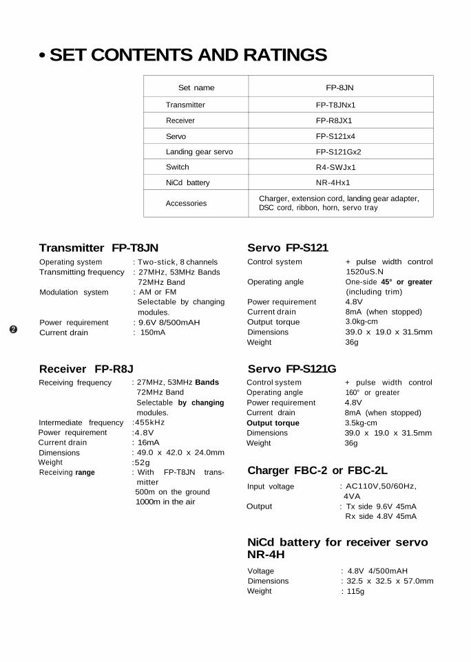
• SET CONTENTS AND RATINGSSet name
Transmitter
Receiver
Servo
Landing gear servo
Switch
NiCd battery
Accessories
FP-8JN
FP-T8JNx1
FP-R8JX1
FP-S121x4
FP-S121Gx2
R4-SWJx1
NR-4Hx1
Charger, extension cord, landing gear adapter,DSC cord, ribbon, horn, servo tray
Transmitter FP-T8JNOperating systemTransmitting frequency
Modulation system
Power requirementCurrent drain
: Two-stick, 8 channels: 27MHz, 53MHz Bands
72MHz Band: AM or FMSelectable by changingmodules.
: 9.6V 8/500mAH: 150mA
Servo FP-S121Control system
Operating angle
Power requirementCurrent drainOutput torqueDimensionsWeight
+ pulse width control1520 uS.NOne-side 45° or greater(including trim)4.8V8mA (when stopped)3.0kg-cm39.0 x 19.0 x 31.5mm36g
Receiver FP-R8JReceiving frequency
Intermediate frequencyPower requirementCurrent drainDimensionsWeightReceiving range
: 27MHz, 53MHz Bands72MHz BandSelectable by changingmodules.
:455kHz:4.8V: 16mA: 49.0 x 42.0 x 24.0mm:52g: With FP-T8JN trans-
mitter500m on the ground1000m in the air
Servo FP-S121GControl systemOperating anglePower requirementCurrent drainOutput torqueDimensionsWeight
+ pulse width control160° or greater4.8V8mA (when stopped)3.5kg-cm39.0 x 19.0 x 31.5mm36g
: AC110V,50/60Hz,4VA
: Tx side 9.6V 45mARx side 4.8V 45mA
Charger FBC-2 or FBC-2LInput voltage
Output
NiCd battery for receiver servoNR-4HVoltageDimensionsWeight
: 4.8V 4/500mAH: 32.5 x 32.5 x 57.0mm: 115g

• TRANSMITTER CONTROLS
Fig.1

Purpose of switches and trimmers in Fig. 2
The numbers in circles represent the channelnumber. The channel numbers on the front ofthe transmitter correspond to the receiverconnector output numbers.Aileron reverse switch
NORM-REV This switch reverses the di-rection of rotation of the aileron servo.
Elevator reverse switchNORM-REV This switch reverses the di-rection of operation of the elevator servo.
Throttle reverse switchNORM-REV This switch reverses the di-rection of operation of the throttle servo.
Rudder reverse switchNORM-REV This switch reverses the di-rection of operation of the rudder servo.
ALT (Adjustable Limit Throttle)This switch selects whether the operating angleis varied at the HIGH side of the stick or theLOW side of the stick when the maximumoperating angle of the servo is adjusted with
AIL, ATV-R This trimmer adjusts theaileron travel in the right direction whenthe aileron reverse switch is in the NORMposition.Travel is continuously variable from 50%to 100% of the total travel range.
AIL, ATV-L This trimmer adjusts theaileron travel in the left direction when theaileron reverse switch is in the NORMposition. Adjustment range is the same asthat of above.
AIL DUAL This trimmer adjusts theaileron travel when the aileron dual rate isON. (This trimmer is adjusted at kick down.)Travel is continuously variable from 40%to 100% of the total travel range.
Aileron dual trimmer
Aileron ATVL
the throttle trim. Normally use at the LOWside.Aileron ATV (Adjustable Travel Volume) R

Throttle button trimmerTHROT The throttle servo is operated atthe position set by this trimmer by push-ing the throttle button.The total travel can be set at throttle stickneutral position.
Roll A button trimmer 1 ROLL (A)Roll B button trimmer 1 ROLL (B)This trimmer sets the aileron travel when theroll button is pushed.The travel is variable over the entire travelrange at aileron stick neutral.Snap roll A button aileron trimmerSNAP ROLL (A) 1 AILSnap roll B button aileron trimmerSNAP ROLL (B) 1 AILThese trimmers set the aileron travel when thesnap roll button is pushed.The travel can be varied over the entire travelrange.Snap roll A button elevator trimmerSNAP ROLL(A) 2 ELEVSnap roll B button elevator trimmerSNAP ROLL(B-> 2 ELEVThis trimmer sets the elevator travel in thesame manner as trimmers andSnap roll A button rudder trimmerSNAP ROLL(A) RUDSnap roll B button rudder trimmerSNAP ROLL (B) RUDThese trimmers set the rudder travel in thesame manner as trimmer andElevator, flap MIX trimmerMIX ELEV-> FLAPThis trimmer adjusts the amount of mixingfrom the elevator to the flap.The travel can be varied over the entire travelrange at flap channel neutral.Spoiler (channel 7), flap (channel 6) MIXtrimmerMIX SPOIL-> FLAPThis trimmer adjusts the amount of mixingfrom the spoiler to the flap.Travel range is the same as that of trimmerElevator dual trimmer
ELEV. DUALThis trimmer adjusts the travel at elevator dualrate ON.The travel is continuously variable from 40%to 100% of the total travel range.Channel 6 flap neutral trimmerMIX NEUTRAL
Elevator ATV U trimmerELEV. ATV-U
This trimmer adjusts the elevator travel in theUP direction when the elevator reverse switchis in the NORM position. Adjustment rangeis the same as that of the aileron ATVElevator ATV D trimmer
ELEV. ATV-DThis trimmer adjusts the elevator travel in theDOWN direction when the elevator reverseswitch is in the NORM position. Adjustmentrange is the same as that of the aileron ATVRudder ATV R trimmer
RUD. ATV-RThis trimmer adjusts the rudder travel in theright direction when the rudder reverse switchis in the NORM position. Adjustment range isthe same as that of aileron ATVRudder ATV L trimmer
RUD. ATV-LThis trimmer adjusts the rudder travel inleft direction when the rudder reverse switchis in the NORM position. Adjustment range isthe same as that of aileron ATVTransmitter moduleThe frequency, frequency band and modula-tion method can be changed by changing thismodule. The method of changing this moduleis shown in Fig. 12.Trimmer panelThis panel is removed by sliding it in the di-rection of the OPEN arrow.
This trimmer sets flap neutral at spoiler (chan-nel 7) and flap (channel 6) mixing.Neutral adjustment is possible in all spoilerstates.

• USING THE TRANSMITTERBefore using the transmitter, charge the NiCdbattery.•Connect the DIN connector of the FBC-2L
charger to the charging jack of the transmitterand the 3P connector to the receiver servo NiCdbattery (NR-4H), and plug the charger into anAC110V outlet as shown in Fig. 3. The Tx, Rxcharging indicator LED illuminate to indicate thatthe battery is being charged.
•The charging time is normally 15 hours. But if thebattery has not be used for some time, charge itfor about 20 hours.(If the battery is left in the discharged state for along time, its capacity and life will be adverselyaffected.)
•The transmitter and receiver NiCd batteries canbe charged simultaneously, or independently.
•The battery can usually be used about 10 timesat a rate of about 10 minutes/time.
•Extend the antenna.Pull the first stage of the antenna up and turn itcounterclockwise until it locks as shown in Fig. 4.
•If the antenna is not locked, it will not be con-nected to the internal circuitry.
•The power switch is a lock type switch. When itis set to ON while pulling it forward, the levelmeter pointer will deflect, indicating the antennaoutput. The transmitter is OK if the pointerdeflects to graduation 7 with the antenna ex-tended fully.The pointer indication is different when theantenna is contracted and when it is extendedfully.[The pointer indication will also be differentwhen the antenna is grasped with your hand andwhen it is not grasped.)When the antenna is contracted, the transmitterdoes not deliver an output even though the levelmeter pointer deflects. DO NOT USE THETRANSMITTER UNDER THIS STATE.
•Push the battery check switch. The level meterpointer will indicate the battery voltage at thistime. The battery is OK if the meter pointer de-flects to within the green zone. If the pointer de-flects to near the boundary between the greenand red zones, recharge the battery.
•Using the D.S.C. functionThe servos can be operated without transmittingby connecting the D.S.C. cord furnished with theset to the connector (Fig. 1 ) of the trans-
(Use this function with the power switch of thetransmitter set to the OFF position. Althoughthe D.S.C. Function will be operative when thepower switch is set to ON, it will be meaningless.)
•Using dual travel(DR —aileron, DR —elevator)When the dual travel switch is set to ON, thesteering angle becomes small (within the rangeindicated by the hatched lines in Fig. 5). Thesteering angle can be varied from 40% (minimum)to 100% (maximum) of the total steering angleby adjusting the trimmer
mitter and the C terminal of the receiver. Thisallows adjustment of the aircraft while awaitingyour turn to fly.
on the trimmer panel for channel 8)next to the switch with a screwdriver. The dualswitch should normally be set to OFF. However
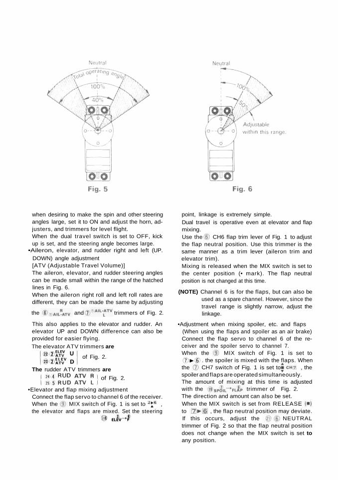
when desiring to make the spin and other steeringangles large, set it to ON and adjust the horn, ad-justers, and trimmers for level flight.When the dual travel switch is set to OFF, kickup is set, and the steering angle becomes large.
•Aileron, elevator, and rudder right and left (UP.DOWN) angle adjustment[ATV (Adjustable Travel Volume)]The aileron, elevator, and rudder steering anglescan be made small within the range of the hatchedlines in Fig. 6.When the aileron right roll and left roll rates aredifferent, they can be made the same by adjusting
the and trimmers of Fig. 2.
This also applies to the elevator and rudder. Anelevator UP and DOWN difference can also beprovided for easier flying.The elevator ATV trimmers are
point, linkage is extremely simple.Dual travel is operative even at elevator and flapmixing.Use the CH6 flap trim lever of Fig. 1 to adjustthe flap neutral position. Use this trimmer is thesame manner as a trim lever (aileron trim andelevator trim).Mixing is released when the MIX switch is set tothe center position (• mark). The flap neutralposition is not changed at this time.
(NOTE) Channel 6 is for the flaps, but can also beused as a spare channel. However, since thetravel range is slightly narrow, adjust thelinkage.
•Adjustment when mixing spoiler, etc. and flaps(When using the flaps and spoiler as an air brake)Connect the flap servo to channel 6 of the re-ceiver and the spoiler servo to channel 7.
of Fig. 2.
The rudder ATV trimmers areof Fig. 2.
•Elevator and flap mixing adjustmentConnect the flap servo to channel 6 of the receiver.When the MIX switch of Fig. 1 is set tothe elevator and flaps are mixed. Set the steering
When the MIX switch of Fig. 1 is set to. the spoiler is mixed with the flaps. When
the CH7 switch of Fig. 1 is set to , thespoiler and flaps are operated simultaneously.The amount of mixing at this time is adjustedwith the trimmer of Fig. 2.The direction and amount can also be set.When the MIX switch is set from RELEASEto , the flap neutral position may deviate.If this occurs, adjust the NEUTRALtrimmer of Fig. 2 so that the flap neutral positiondoes not change when the MIX switch is set toany position.

MIX switch when releasing mixing.
If these switches are released in the reverseorder, only the flaps will be released andthe spoiler will remain open, placing theaircraft into an extremely dangerous state.
•Roll button A (Fig. 1 ROLL[A])The ailerons can be stopped at an arbitrary posi-tion while this button is being pushed. This is usedat slow roll, etc.Adjust the steering angle with the ROLL(A) trimmer of Fig. 2. Both right roll and left rollcan be adjusted. Neutral adjustment is also pos-sible. (At neutral the button has no effect even ifpushed.)
•Roll button B (Fig. 1 ROLL[B])This is the same as roll button A. Adjust thesteering angle with the ROLL(B) trimmerof Fig. 2. (Using roll button A for right roll androll button B for left roll is extremely convenient.)
•Throttle button (Fig. 1 THROT)The throttle can be stopped at an arbitrary posi-tion while this button is being pushed at snaproll, etc. Adjust by setting the throttle stick toHIGH, and pushing the button.Setting the engine to medium throttle with the
THROT trimmer of Fig. 2 is perfect.•Snap roll button A (Fig. 1 S.ROLL[A])
The aircraft can be placed into a snap roll bysimply pushing this button.The direction and amount of aileron, elevator,and rudder can be freely switched with thetrimmer of Fig. 2.Each servo can also be adjusted to neutral.(At neutral the servos are not operated even ifyou push the button.)
•Snap roll B (Fig. 1 S.ROLL[B])This is similar to snap roll A. The direction andamount of aileron, elevator, and rudder are setwith the trimmer of Fig. 2.Using snap roll button A for right snap roll andsnap roll button B for left snap roll is extremelyconvenient. Adjust to match the aircraft.The snap roll buttons may also be used as spinbuttons.
•Using the aileron, elevator, throttle, and rudderreverses(Devices which reverse the direction of operationof the servos)There must be no play in the aircraft linkagedirection.The switches are built into the module case ofthe transmitter.
Aileron Elevator Throttle Rudder•Throttle ALT (Adjustable Limit Throttle) is a
new mechanism that trims only the LOW side ofthe throttle control.The trim lever is almost inoperative at the throttlestick HIGH side, but is operative at the throttlestick LOW side. The LOW side can be set to anydesired position with the trim lever by setting thethrottle rod at the engine HIGH side. This is veryconvenient because the HIGH side remains un-changed even when the trim lever is operated.Always use with this switch set to the LOW side.
•The elevator trim lever is at the left side and thethrottle trim lever is at the right side. The elevatortrim lever has been placed at the left side becausethe right side (aileron, elevator) has priority inMODE II.
(spoiler) of Fig. 1 before releasingCH7 switch(NOTE) Always release
(NOTE) The buttons should be set to neutral be-fore you are completely familiar with theset. Use these buttons only after you havebecome completely familiar with the set.

• USING THE RECEIVER SERVOS
Aileron servo

•The receiver channel order is shown in Fig. 8.Stick the channel tabs furnished with the set tothe servo lead wires for identification.
•Use an extension cord matched to the fuselage.•Wrap the receiver in sponge and fasten to the
fuselage with rubber bands.•Install the receiver so that the antenna wire is as
straight as possible.•Mount the servo as shown in Fig. 9.•Mount the servos so that the flexible wire,
hinges, and other steering mechanisms operatedsmoothly.Be especially careful when the steering angle islarge.
•When mounting the landing gear servo, match thelanding gear stroke and the landing gear servohorn stroke precisely so that pulling and pushingare neither excessive nor insufficient.
•Install the receiver servo NiCd battery (NR-4H)by wrapping it in sponge and attaching it to thefuselage with rubber bands, the same as thereceiver.
•All the servos can be controlled from the receiver(direct servo control system) by applying thesignals form the transmitter to terminal C of thereceiver. In this case the transmitter current drainwill drop to about 1/4 that when transmitting.Connect the intermediate cord with lug to ter-minal C and fastening it to the side of the fuselageas shown in Fig. 8 beforehand.
•All the servos, except the landing gear servo, aredesigned and manufactured to the same standardsand can be used at any channel.
•Pay careful attention to noise.This set is especially resistant to noise, but is notcompletely noise-free.The use of noiseless parts is recommended.
•When used in seaplanes and boats, pay carefulattention to waterproofing.The servos are waterproof, but the receiver, con-nectors, and NiCd battery are not. Place thesecomponents in a vinyl bag and amply waterproofthe entire mechanism chamber.
No.
1
2
34
5
67
8
9
10
11
12
13
14
15
1617
18
19
20
21
22
23
24
25
26
27
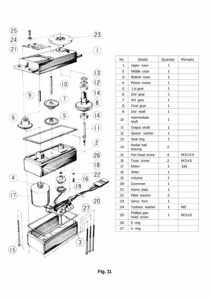
Details
Upper case
Middle case
Bottom case
Pinion motor
1 st gear
2nd gear
3rd gear
Final gear
2nd shaft
Intermediateshaft
Output shaft
Spacer washer
Seal ring
Radial ballbearing
Pan head screw
Truss screwMotor
Slider
Volume
Grommet
Name plate
Fiber washer
Servo horn
Toothed washer
Phillips panhead screw
E ring
0 ring
Quantity
1
1
1
1
1
11
1
1
1
1
1
1
2
4
21
1
1
1
1
2
1
1
1
Remarks
M2x24
M2x5
16
M2
M2x5
Fig. 11

• MODULESThe frequency, frequency band, and modulation(AM, FM) of the J Module Series can be changed.The transmitting and receiving modules are availa-ble as a pair.
EXAMPLE 1. : Switching from 27.195MHz to27.045MHzReplace both the transmitting andreceiving modules with the 27.045MHz RF module.
EXAMPLE 2. : Switching from 27.145MHz to72.080MHzReplace both the transmitting andreceiving modules with the 72.080MHz RF module.
EXAMPLE 3. : Switching from 72.240MHz to53.400MHz (AM)Replace both the transmitting andreceiving modules with the 53.400MHz (AM) RF module.
EXAMPLE 4. : Switching from 72.080MHz to53.200MHz (FM)Replace both the transmitting andreceiving modules with the 53.200MHz (FM) RF module, and alsoreplace the receiver with an FMreceiver.
EXAMPLE 5. : Switching from 53.100MHz (FM)to 53.500MHz (AM)Replace both the transmitting andreceiving modules with the 53.500MHz (AM) RF module, and replacethe receiver with an AM receiver.
GUARANTEE
Your NEW FUTABA Digital Proportional R/C system is guaranteed against defects inworkmanship and material for 180 days from the date of purchase when the attachedregistration card is returned to us within ten days of purchase.
This Guarantee is null and void if the R/C system has been improperly handled,damaged in a crash, or tampered with and does not cover the replacement of plastichousings or electronic components damaged due to the use of improper voltages.
When service is required, please take your equipment to your local authorized servicestation or ship it directly to us. All postage, shipping, and insurance changes must bepaid by the user.
This guarantee only applies to the continental U.S.A., Hawaii, and Alaska.
This factory repair service applies only to the continental U.S.A., Hawaii, and Alaska.
To insure prompt service, please follow the instructions given below.1. Charge the batteries for at least 18 hours prior to shipment.2. Return the system only. Not your complete installation. Remove the servos from their mounts
and remove the foam padding from the receiver.3. Plugs or other modifications which interfere with factory test procedures will be returned to
factory standard at your expense.4. Carefully pack all components individually, using sufficient packing material to prevent damage
during shipment.5. Include a brief but thorough explanation of all problems and service required and tape it to
the back of the transmitter. Place a label describing the functions of the servo on each servo.6. Be sure to include your full address and zip code inside the box as well as on the outside.7. Include a packing list of all items being returned, and double check to make sure that all items
are packed.8. Upon receipt of damaged equipment at the FUTABA factory, an estimate of the cost of repair
w i l l be sent to you. Your equipment will then be repaired and returned to you upon receipt ofpayment.
FACTORY REPAIR SERVICE
