fundamentals of stress analysis - lec 05-1
Post on 14-Apr-2016
21 views
DESCRIPTION
stressTRANSCRIPT

MansouraMansoura UniversityUniversity -- Faculty of Faculty of EngineeringEngineeringProduction and Mechanical Design Engineering DepartmentProduction and Mechanical Design Engineering Department

PRE5311- Fundamentals of Stress Analysis - Lecture No. (5) : Strain and material properties.Dr. T. A. ENAB, Production & Mechanical Design Engineering Department, Faculty of Engineering, Mansoura University. 22

EquationsEquations ofof CompatibilityCompatibility:: The concept of compatibility has both mathematical and physical The concept of compatibility has both mathematical and physicalsignificance.
F th ti l i t f i it t th t th di l t From a mathematical point of view, it asserts that the displacements u, v,and w match the geometrical boundary conditions and are single-valued andcontin o s f nctions of position ith hich the strain components arecontinuous functions of position with which the strain components areassociated.
Ph i ll hi h h b d b i d h id Physically, this means that the body must be pieced together; no voids arecreated in the deformed body.
Kinematic relations connect six components of strain to only threecomponents of displacement
PRE5311- Fundamentals of Stress Analysis - Lecture No. (5) : Strain and material properties.Dr. T. A. ENAB, Production & Mechanical Design Engineering Department, Faculty of Engineering, Mansoura University. 33

EquationsEquations ofof CompatibilityCompatibility::We cannot therefore arbitrarily specify all the strains as functions of x yWe cannot therefore arbitrarily specify all the strains as functions of x, y,and z (strains are evidently not independent of one another).
I t di i l t i diff ti ti f t i ith t In two-dimensional strain, differentiation of εx twice with respectto y, εy twice with respect to x, and γxy with respect to x and y results in:
Or
This is the condition of compatibility of the two-dimensional problem,f p y p ,expressed in terms of strain.
PRE5311- Fundamentals of Stress Analysis - Lecture No. (5) : Strain and material properties.Dr. T. A. ENAB, Production & Mechanical Design Engineering Department, Faculty of Engineering, Mansoura University. 44

EquationsEquations ofof CompatibilityCompatibility:: The three dimensional equations of compatibility are obtained in a like The three-dimensional equations of compatibility are obtained in a likemanner:
To gain further insight into the meaning of compatibility, imagine an elasticbody subdivided into a number of small cubic elements prior toy pdeformation. These cubes may, upon loading, be deformed into a system ofparallelepipeds. The deformed system will, in general, be impossible top p p y , g , parrange in such a way as to compose a continuous body unless thecomponents of strain satisfy the equations of compatibility
PRE5311- Fundamentals of Stress Analysis - Lecture No. (5) : Strain and material properties.Dr. T. A. ENAB, Production & Mechanical Design Engineering Department, Faculty of Engineering, Mansoura University. 55

StateState ofof StrainStrain atat aa PointPoint:: Consider a small linear element AB of length ds is an unstrained body (Fig Consider a small linear element AB of length ds is an unstrained body (Fig.-a). After straining, AB is displaced to position A′B′ and is now ds′ long.The x and y displacements are u + du and v + dv respectivelyThe x and y displacements are u + du and v + dv, respectively.
The variation with position of the displacement is expressed by a truncatedTa lor’s e pansion as follo s:Taylor’s expansion as follows:
Fig. (b) shows the relative displacement of B with respect to A. It isb d h AB h b l d h A i id i h A′ i i iobserved that AB has been translated so that A coincides with A′; it is now inthe position A′B″. Here B″ D = du and DB′ = dv are the components ofdi l tdisplacement.
PRE5311- Fundamentals of Stress Analysis - Lecture No. (5) : Strain and material properties.Dr. T. A. ENAB, Production & Mechanical Design Engineering Department, Faculty of Engineering, Mansoura University. 66

TransformationTransformation ofof TwoTwo--DimensionalDimensional StrainStrain:: For x′ y′ coordinate system the components of strain are: ε ε γ For x y coordinate system the components of strain are: εx′, εy′, γx′y′.
First we determine the unit elongation of ds′, εx′. The projectionsf d d d th ′ i ft t ki EB′ EB′(1) b i t f thof du and dv on the x′ axis, after taking EB′ cos α = EB′(1) by virtue of thesmall angle approximation, lead to the approximation:
By definition, εx′ is found from EB′/ds. Thus, we obtain:
Substituting cos θ for dx/ds, sin θ for dy/ds, we have:
This represents the transformation equation for the x-directed normal strain,which through the use of trigonometric identities may be converted to thewhich, through the use of trigonometric identities, may be converted to theform
The normal strain ε is determined by replacing θ by θ + π/2PRE5311- Fundamentals of Stress Analysis - Lecture No. (5) : Strain and material properties.Dr. T. A. ENAB, Production & Mechanical Design Engineering Department, Faculty of Engineering, Mansoura University. 77
The normal strain εy′ is determined by replacing θ by θ + π/2

TransformationTransformation ofof TwoTwo--DimensionalDimensional StrainStrain:: For shearing strain γ we first determine the angle α through which AB is For shearing strain γx′y′, we first determine the angle α through which AB isrotated.
t B″ E/d h B″E d θ d i θ EB′ i tan α = B″ E/ds, where B″E = dv cos θ – du sin θ – EB′ sin α.
By letting: sin α = tan α = α, we have EB′ sin α = εx′ ds α = 0.
The latter is a consequence of the smallness of both εx′ and α.
Substituting into B″E, α = B″E/ds may be written as follows:g y
The angular displacement of y′ is readily derived by replacing θ by θ + π/2 The angular displacement of y is readily derived by replacing θ by θ + π/2in Eq.:
PRE5311- Fundamentals of Stress Analysis - Lecture No. (5) : Strain and material properties.Dr. T. A. ENAB, Production & Mechanical Design Engineering Department, Faculty of Engineering, Mansoura University. 88

TransformationTransformation ofof TwoTwo--DimensionalDimensional StrainStrain:: Taking counterclockwise rotations to be positive in finding the shear strain Taking counterclockwise rotations to be positive in finding the shear strainγx′y′, to add α and –αθ + π/2. By so doing and substituting γxy = ∂v/∂x + ∂u/∂y,we obtain:we obtain:
Through the use of trigonometric identities, this expression for thetransformation of the shear strain becomes:
It is observed that transformations expressions for stress are converted intostrain relationships by replacing:
PRE5311- Fundamentals of Stress Analysis - Lecture No. (5) : Strain and material properties.Dr. T. A. ENAB, Production & Mechanical Design Engineering Department, Faculty of Engineering, Mansoura University. 99

TransformationTransformation ofof TwoTwo--DimensionalDimensional StrainStrain:: The principal strain directions (where γ = 0) are found from: The principal strain directions (where γx′y′ = 0) are found from:
The magnitudes of the principal strains are:
The maximum shearing strains are found on planes 45° relative to the The maximum shearing strains are found on planes 45 relative to theprincipal planes and are given by:
PRE5311- Fundamentals of Stress Analysis - Lecture No. (5) : Strain and material properties.Dr. T. A. ENAB, Production & Mechanical Design Engineering Department, Faculty of Engineering, Mansoura University. 1010

TransformationTransformation ofof ThreeThree--DimensionalDimensional StrainStrain:: This case may also proceed from the corresponding stress relations by This case may also proceed from the corresponding stress relations byreplacing σ by ε and τ by γ/2. Therefore, we have:
where l1 is the cosine of the angle between x and x′, m1 is the cosine of theangle between y and x′, and so on.
PRE5311- Fundamentals of Stress Analysis - Lecture No. (5) : Strain and material properties.Dr. T. A. ENAB, Production & Mechanical Design Engineering Department, Faculty of Engineering, Mansoura University. 1111

TransformationTransformation ofof ThreeThree--DimensionalDimensional StrainStrain:: The foregoing equations are succinctly expressed as follow: The foregoing equations are succinctly expressed as follow:
or conversely
These equations represent the law of transformation for a strain tensor ofrank 2.
The principal strains in 3D are the roots of the following cubic equation:
The strain invariants are:
PRE5311- Fundamentals of Stress Analysis - Lecture No. (5) : Strain and material properties.Dr. T. A. ENAB, Production & Mechanical Design Engineering Department, Faculty of Engineering, Mansoura University. 1212

Mohr’sMohr’s CircleCircle forfor PlanePlane StrainStrain:: The transformation properties of stress and strain are identical The transformation properties of stress and strain are identical
The construction technique of Mohr’s circle for strain does not differ fromth t f M h ’ i l f tthat of Mohr’s circle for stress.
In Mohr’s circle for strain, the normal strains are plotted on the horizontalaxis, positive to the right.
When the shear strain is positive, the point representing the x axis strains isplotted a distance γ/2 below the ε line, and the y axis point a distanceγ/2 above the ε line, and vice versa when the shear strain is negative.
PRE5311- Fundamentals of Stress Analysis - Lecture No. (5) : Strain and material properties.Dr. T. A. ENAB, Production & Mechanical Design Engineering Department, Faculty of Engineering, Mansoura University. 1313

Mohr’sMohr’s CircleCircle forfor PlanePlane StrainStrain:: Example: State of Plane Strain in a Plate Example: State of Plane Strain in a Plate
The state of strain at a point on a thin plate is given by εx = 510 μ, εy =120 d 260 D t i i M h ’ i l f t i ( ) th120 μ, and γxy = 260 μ. Determine, using Mohr’s circle of strain, (a) thestate of strain associated with axes x′, y′, which make an angle θ = 30°ith the a es ; (b) the principal strains and directions of the principalwith the axes x, y; (b) the principal strains and directions of the principalaxes; (c) the maximum shear strains and associated normal strains; displaythe given data and the results obtained on properly oriented elements ofthe given data and the results obtained on properly oriented elements ofunit dimensions.
PRE5311- Fundamentals of Stress Analysis - Lecture No. (5) : Strain and material properties.Dr. T. A. ENAB, Production & Mechanical Design Engineering Department, Faculty of Engineering, Mansoura University. 1414

Mohr’sMohr’s CircleCircle forfor PlanePlane StrainStrain:: Point C: (ε + ε )/2 Point C: (εx+ εy)/2
Point A: (εx , γxy/2)
Point B: (εy , -γxy/2)
Mohr’s circle radius: r = (1952 + 1302)1/2 μ = 234 μMohr s circle radius: r (195 + 130 ) μ 234 μ
For principal strains angle:
Th t i t i t d ith ′ ′ The strain components associated with x′y′ are:
The principal strains are:
PRE5311- Fundamentals of Stress Analysis - Lecture No. (5) : Strain and material properties.Dr. T. A. ENAB, Production & Mechanical Design Engineering Department, Faculty of Engineering, Mansoura University. 1515
p p

Mohr’sMohr’s CircleCircle forfor PlanePlane StrainStrain:: Points D and E represent the maximum shear strains Thus: γ = ±468 μ Points D and E represent the maximum shear strains. Thus: γmax = ±468 μ
PRE5311- Fundamentals of Stress Analysis - Lecture No. (5) : Strain and material properties.Dr. T. A. ENAB, Production & Mechanical Design Engineering Department, Faculty of Engineering, Mansoura University. 1616

Hooke’sHooke’s LawLaw andand Poisson’sPoisson’s RatioRatio::Most structural materials exhibit an initial region of the stress strainMost structural materials exhibit an initial region of the stress–straindiagram in which the material behaves both elastically and linearly.
Thi li l i i i t l i t t i i i b This linear elasticity is extremely important in engineering because manystructures and machines are designed to experience relatively smalldeformationsdeformations.
For that straight-line portion of the stress–strain diagram, stress is directlyi l iproportional to strain.
If the normal stress acts in the x direction:
This relationship is known as Hooke’s law, (Robert Hooke 1635–1703).
The constant E is called the modulus of elasticity, or Young’s modulus, inf y, g ,honor of Thomas Young (1773–1829).
As ε is a dimensionless quantity, E has the units of σ.
PRE5311- Fundamentals of Stress Analysis - Lecture No. (5) : Strain and material properties.Dr. T. A. ENAB, Production & Mechanical Design Engineering Department, Faculty of Engineering, Mansoura University. 1717
As ε is a dimensionless quantity, E has the units of σ.

Hooke’sHooke’s LawLaw andand Poisson’sPoisson’s RatioRatio:: Graphically E is the slope of the stress strain diagram in the linearly elastic Graphically, E is the slope of the stress–strain diagram in the linearly elasticregion.
El ti it i il l b d i t di i l h Elasticity can similarly be measured in two-dimensional pure shear.
It is found experimentally that, in the linearly elastic range, stress and strainare related by Hooke’s law in shear:
Here G is the shear modulus of elasticity or modulus of rigidity. Like E, G isa constant for a given material.
Since, the axial tensile loading induces a reduction or lateral contraction of aspecimen’s cross-sectional area.
Similarly, a contraction owing to an axial compressive load is accompaniedy, g p pby a lateral extension.
PRE5311- Fundamentals of Stress Analysis - Lecture No. (5) : Strain and material properties.Dr. T. A. ENAB, Production & Mechanical Design Engineering Department, Faculty of Engineering, Mansoura University. 1818

Hooke’sHooke’s LawLaw andand Poisson’sPoisson’s RatioRatio:: In the linearly elastic region it is found experimentally that lateral strains In the linearly elastic region, it is found experimentally that lateral strains,say in the y and z directions, are related by a constant of proportionality, v,to the axial strain caused by uniaxial stress only ε = σ /E in the x direction:to the axial strain caused by uniaxial stress only εx = σx/E, in the x direction:
Alternatively, the definition of v may be stated as:
Here v is known as Poisson’s ratio, (S. D. Poisson 1781–1840), whocalculated v to be ¼ for isotropic materials employing molecular theory.
Note that more recent calculations based on a model of atomic structureyield v=⅓.
Both values given here are close to the actual measured values, 0.25 to 0.35g ,for most metals.
PRE5311- Fundamentals of Stress Analysis - Lecture No. (5) : Strain and material properties.Dr. T. A. ENAB, Production & Mechanical Design Engineering Department, Faculty of Engineering, Mansoura University. 1919

Hooke’sHooke’s LawLaw andand Poisson’sPoisson’s RatioRatio:: Volume Change: Volume Change:
The lateral contraction of a cubic element from a bar in tension isill t t d i Fi h it i d th t th f f th l t t thillustrated in Fig., where it is assumed that the faces of the element at theorigin are fixed in position.
From the figure, subsequent to straining, the final volume is:
Expanding and neglecting terms involving εx2 and εx
3:
Vf = [1 + (εx – 2νεx)] dx dy dz = Vo + ΔVf [ ( x x)] y o
where Vo is the initial volume dx dy dz and ΔV is the change in volume.
The it l h also referred to as the dil t ti ma no beThe unit volume change e, also referred to as the dilatation, may now beexpressed in the form:
PRE5311- Fundamentals of Stress Analysis - Lecture No. (5) : Strain and material properties.Dr. T. A. ENAB, Production & Mechanical Design Engineering Department, Faculty of Engineering, Mansoura University. 2020

Hooke’sHooke’s LawLaw andand Poisson’sPoisson’s RatioRatio:: Example: Deformation of a Tension Bar Example: Deformation of a Tension Bar
An aluminum alloy bar of circular cross-sectional area A and length L isbj t d t i l t il f P (Fi ) Th d l f l ti it dsubjected to an axial tensile force P (Fig.). The modulus of elasticity and
Poisson’s ratio of the material are E and v, respectively. For the bar,determine (a) the a ial deformation; (b) the change in diameter d; and (c)determine (a) the axial deformation; (b) the change in diameter d; and (c)the change in volume ΔV. (d) Evaluate the numerical values of thequantities obtained in (a) through (c) for the case in which P = 60 kN d =quantities obtained in (a) through (c) for the case in which P = 60 kN, d =25 mm, L = 3 m, E = 70 GPa, ν = 0.3, and the yield strength σyp = 260 MPa.
S l ti Solution:
If the resulting axial stress σ = P/A does not exceed the proportionallimit of the material, we may apply Hooke’s law and write σ = Eε.
Also, the axial strain is defined by ε = δ/L.
PRE5311- Fundamentals of Stress Analysis - Lecture No. (5) : Strain and material properties.Dr. T. A. ENAB, Production & Mechanical Design Engineering Department, Faculty of Engineering, Mansoura University. 2121

Hooke’sHooke’s LawLaw andand Poisson’sPoisson’s RatioRatio::The preceding expressions can be combined to yield the axialThe preceding expressions can be combined to yield the axialdeformation:
h th d t AE i k th i l i idi f th bwhere the product AE is known as the axial rigidity of the bar.
The change in diameter equals the product of transverse or lateral strainand diameter: εtd = –νεd. Thus:
The change in volume, substituting Vo = AL and εx = P/AE, is:
For A = (π/4)(252) = 490.9(10–6) m2, the axial stress σ in the bar is( )( ) ( ) ,obtained from: < σyield (260 Mpa).
Thus we have:Thus, we have:
PRE5311- Fundamentals of Stress Analysis - Lecture No. (5) : Strain and material properties.Dr. T. A. ENAB, Production & Mechanical Design Engineering Department, Faculty of Engineering, Mansoura University. 2222
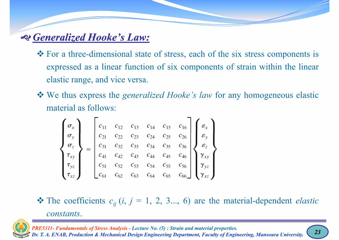
GeneralizedGeneralized Hooke’sHooke’s LawLaw:: For a three dimensional state of stress each of the six stress components is For a three-dimensional state of stress, each of the six stress components isexpressed as a linear function of six components of strain within the linearelastic range and vice versaelastic range, and vice versa.
We thus express the generalized Hooke’s law for any homogeneous elasticmaterial as follo s:material as follows:
The coefficients cij (i, j = 1, 2, 3..., 6) are the material-dependent elasticconstants
PRE5311- Fundamentals of Stress Analysis - Lecture No. (5) : Strain and material properties.Dr. T. A. ENAB, Production & Mechanical Design Engineering Department, Faculty of Engineering, Mansoura University. 2323
constants.

GeneralizedGeneralized Hooke’sHooke’s LawLaw:: A brief representation of the preceding stress strain relationships are given A brief representation of the preceding stress–strain relationships are givenin the following form:
Th i i f b i t f d fi iti t f t The cmnij requiring four subscripts for definition, are components of a tensorof rank 4. We note that, to avoid repetitive subscripts, the materialconstants are denotedconstants c1111, c1122, ..., c6666are denoted c11, c12, ..., c66
For homogeneous material, each of the 36 constants cij has the same valuell iat all points.
For material without any planes of symmetry (fully anisotropic), cij = cji;thus the number of independent material constants can be as large as 21.
For orthotropic material, the number of constants reduces to nine.
For isotropic material which has every plane as a plane of symmetry thenumber of essential elastic constants reduces to two.
PRE5311- Fundamentals of Stress Analysis - Lecture No. (5) : Strain and material properties.Dr. T. A. ENAB, Production & Mechanical Design Engineering Department, Faculty of Engineering, Mansoura University. 2424

GeneralizedGeneralized Hooke’sHooke’s LawLaw:: For a two dimensional homogeneous isotropic rectangular element of unit For a two-dimensional homogeneous isotropic rectangular element of unitthickness, subjected to a biaxial state of stress (Fig.).
A li ti f l ld lt i di t t i /E d t ti Application of σx alone would result in direct strain σx/E and a y contractionwould take place as well, –νσx/E.
Application of σy alone would result in an x contraction –νσy/E anda y strain σy/E.
The simultaneous action of σx and σy, applying the principle ofsuperposition, leads to the following strains:
For pure shear, stress and strain are related by:p , y
PRE5311- Fundamentals of Stress Analysis - Lecture No. (5) : Strain and material properties.Dr. T. A. ENAB, Production & Mechanical Design Engineering Department, Faculty of Engineering, Mansoura University. 2525

GeneralizedGeneralized Hooke’sHooke’s LawLaw:: Similar analysis enables us to express the components ε γ and γ of Similar analysis enables us to express the components εz, γyz, and γxz ofstrain in terms of stress and material properties.
I th f th di i l t t f t thi d l d t In the case of a three-dimensional state of stress, this procedure leads tothe generalized Hooke’s law, valid for an isotropic homogeneous material:
The elastic constants E, v, and G are related, serving to reduce the numberof independent constants in the above Eq to twoof independent constants in the above Eq. to two.
PRE5311- Fundamentals of Stress Analysis - Lecture No. (5) : Strain and material properties.Dr. T. A. ENAB, Production & Mechanical Design Engineering Department, Faculty of Engineering, Mansoura University. 2626
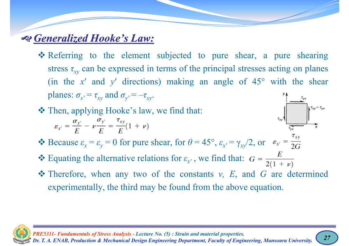
GeneralizedGeneralized Hooke’sHooke’s LawLaw:: Referring to the element subjected to pure shear a pure shearing Referring to the element subjected to pure shear, a pure shearingstress τxy can be expressed in terms of the principal stresses acting on planes(in the x′ and y′ directions) making an angle of 45° with the shear(in the x and y directions) making an angle of 45 with the shearplanes: σx′ = τxy and σy′ = –τxy.
Then appl ing Hooke’s la e find that: Then, applying Hooke’s law, we find that:
Because εx = εy = 0 for pure shear, for θ = 45°, εx′ = γxy/2, or
Equating the alternative relations for εx′ , we find that:
Therefore, when any two of the constants ν, E, and G are determinedexperimentally, the third may be found from the above equation.p y, y q
PRE5311- Fundamentals of Stress Analysis - Lecture No. (5) : Strain and material properties.Dr. T. A. ENAB, Production & Mechanical Design Engineering Department, Faculty of Engineering, Mansoura University. 2727
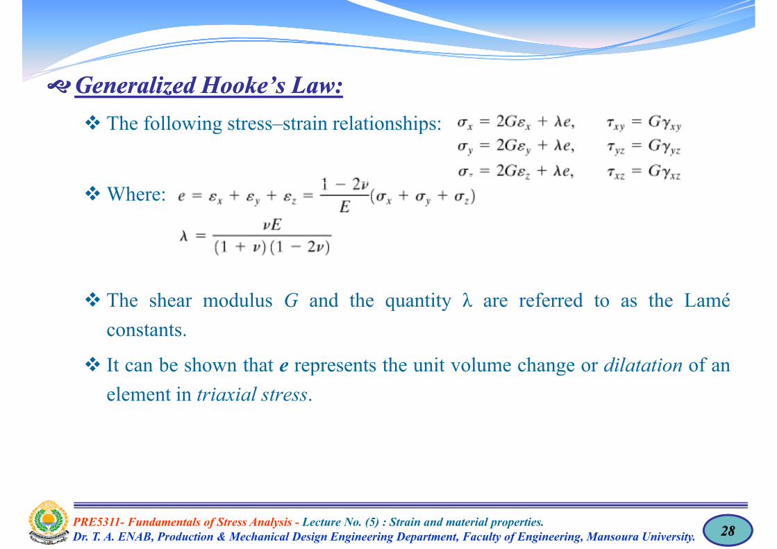
GeneralizedGeneralized Hooke’sHooke’s LawLaw:: The following stress strain relationships: The following stress–strain relationships:
Where:
The shear modulus G and the quantity λ are referred to as the Lamé The shear modulus G and the quantity λ are referred to as the Laméconstants.
It can be shown that e represents the unit volume change or dilatation of an It can be shown that e represents the unit volume change or dilatation of anelement in triaxial stress.
PRE5311- Fundamentals of Stress Analysis - Lecture No. (5) : Strain and material properties.Dr. T. A. ENAB, Production & Mechanical Design Engineering Department, Faculty of Engineering, Mansoura University. 2828
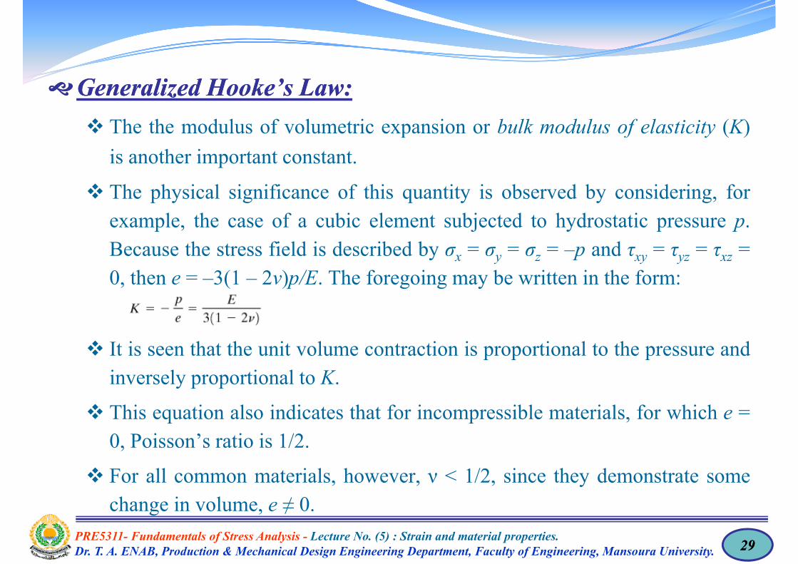
GeneralizedGeneralized Hooke’sHooke’s LawLaw:: The the modulus of volumetric expansion or bulk modulus of elasticity (K) The the modulus of volumetric expansion or bulk modulus of elasticity (K)is another important constant.
Th h i l i ifi f thi tit i b d b id i f The physical significance of this quantity is observed by considering, forexample, the case of a cubic element subjected to hydrostatic pressure p.Because the stress field is described by σ = σ = σ = –p and τ = τ = τ =Because the stress field is described by σx = σy = σz = –p and τxy = τyz = τxz =0, then e = –3(1 – 2ν)p/E. The foregoing may be written in the form:
It is seen that the unit volume contraction is proportional to the pressure andinversely proportional to Kinversely proportional to K.
This equation also indicates that for incompressible materials, for which e =0 Poisson’s ratio is 1/20, Poisson’s ratio is 1/2.
For all common materials, however, ν < 1/2, since they demonstrate someh i l ≠ 0
PRE5311- Fundamentals of Stress Analysis - Lecture No. (5) : Strain and material properties.Dr. T. A. ENAB, Production & Mechanical Design Engineering Department, Faculty of Engineering, Mansoura University. 2929
change in volume, e ≠ 0.
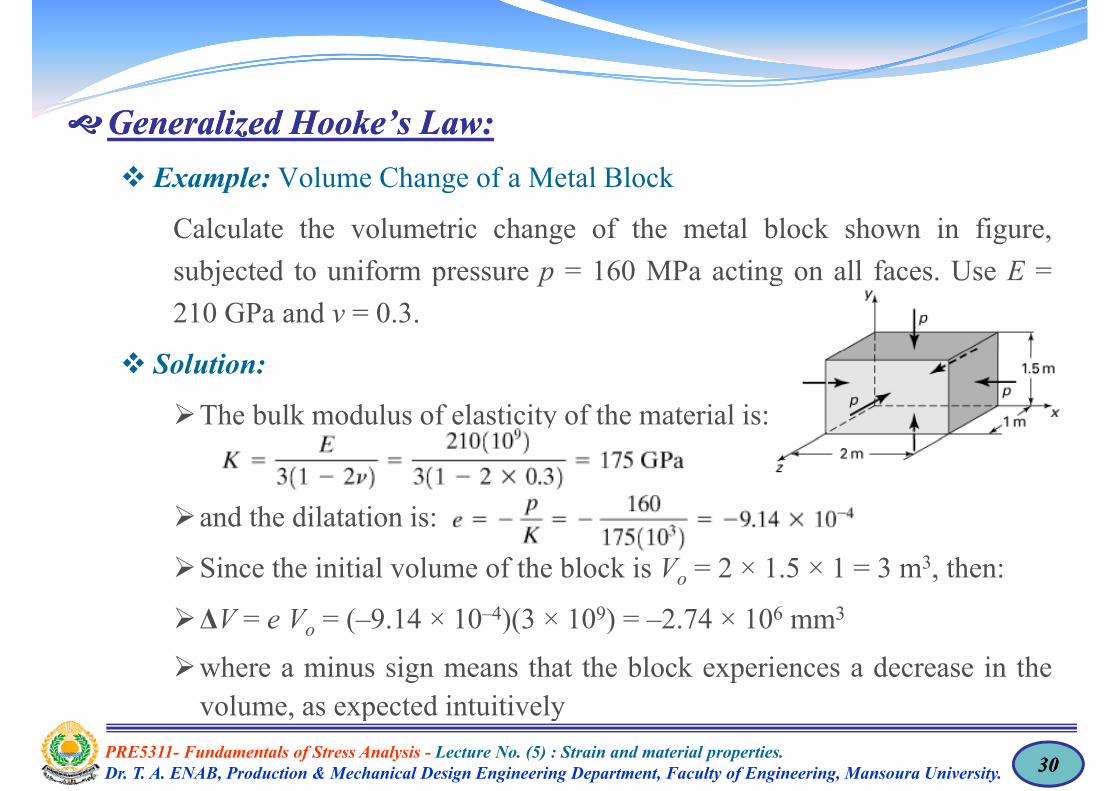
GeneralizedGeneralized Hooke’sHooke’s LawLaw:: Example: Volume Change of a Metal Block Example: Volume Change of a Metal Block
Calculate the volumetric change of the metal block shown in figure,bj t d t if 160 MP ti ll f U Esubjected to uniform pressure p = 160 MPa acting on all faces. Use E =
210 GPa and ν = 0.3.
Solution:
The bulk modulus of elasticity of the material is:
and the dilatation is:
Since the initial volume of the block is Vo = 2 × 1.5 × 1 = 3 m3, then:
ΔV V ( 9 14 × 10–4)(3 × 10⁹) 2 74 × 106 mm3ΔV = e Vo = (–9.14 × 10⁻⁴)(3 × 10⁹) = –2.74 × 106 mm3
where a minus sign means that the block experiences a decrease in thevolume as expected intuitively
PRE5311- Fundamentals of Stress Analysis - Lecture No. (5) : Strain and material properties.Dr. T. A. ENAB, Production & Mechanical Design Engineering Department, Faculty of Engineering, Mansoura University. 3030
volume, as expected intuitively

Hooke’sHooke’s LawLaw forfor OrthotropicOrthotropic MaterialsMaterials:: A general orthotropic material has three planes of symmetry and three A general orthotropic material has three planes of symmetry and threecorresponding orthogonal axes called the orthotropic axes.
Withi h l f t t i l ti b diff t dWithin each plane of symmetry, material properties may be different andindependent of direction.
A familiar example of such an orthotropic material is wood.
Strength and stiffness of wood along its grain and in each of the twoperpendicular directions vary.
These properties are greater in a direction parallel to the fibers than in thetransverse direction.
A polymer reinforced by parallel glass or graphite fibers represents a typicalp y y p g g p p yporthotropic material with two axes of symmetry.
PRE5311- Fundamentals of Stress Analysis - Lecture No. (5) : Strain and material properties.Dr. T. A. ENAB, Production & Mechanical Design Engineering Department, Faculty of Engineering, Mansoura University. 3131
Hooke’sHooke’s LawLaw forfor OrthotropicOrthotropic MaterialsMaterials::Materials such as corrugated and rolled metal sheet reinforced concreteMaterials such as corrugated and rolled metal sheet, reinforced concrete,various composites, gridwork, and particularly laminates can also be treatedas orthotropicas orthotropic.
We note that a gridwork consists of two systems of equally spaced parallelribs (beams) m t all perpendic lar and attached rigidl at the points ofribs (beams), mutually perpendicular and attached rigidly at the points ofintersection.
F l i h i i l h l i ffi i i For an elastic orthotropic material, the elastic coefficients cij remaininvariant at a point under a rotation of 180° about any of the orthotropicaxes.
In the following derivations, we shall assume that the directions oforthotropic axes are parallel to the directions of the x, y, and z coordinates.
PRE5311- Fundamentals of Stress Analysis - Lecture No. (5) : Strain and material properties.Dr. T. A. ENAB, Production & Mechanical Design Engineering Department, Faculty of Engineering, Mansoura University. 3232

Hooke’sHooke’s LawLaw forfor OrthotropicOrthotropic MaterialsMaterials:: First let the xy plane be a plane material symmetry and rotate Oz through First, let the xy plane be a plane material symmetry and rotate Oz through180°. Accordingly, under the coordinate transformation x: x′, y: y′, and z: –z′ the direction cosines are:z , the direction cosines are:
Then we have:
Inasmuch as the cij remain the same:
Therefore, from the above equations:
PRE5311- Fundamentals of Stress Analysis - Lecture No. (5) : Strain and material properties.Dr. T. A. ENAB, Production & Mechanical Design Engineering Department, Faculty of Engineering, Mansoura University. 3333

Hooke’sHooke’s LawLaw forfor OrthotropicOrthotropic MaterialsMaterials:: Thus c = c c = c implying that c = c = 0 Thus, c15 = –c15, c16 = –c16, implying that c15 = c16 = 0.
Likewise, considering σy′, σz′, τx′y′, τy′z′, τx′z′, we obtainth t 0that c25 = c26 = c35 = c36 = c45 = c46 = 0.
The elastic coefficient matrix [cij] is therefore:
PRE5311- Fundamentals of Stress Analysis - Lecture No. (5) : Strain and material properties.Dr. T. A. ENAB, Production & Mechanical Design Engineering Department, Faculty of Engineering, Mansoura University. 3434
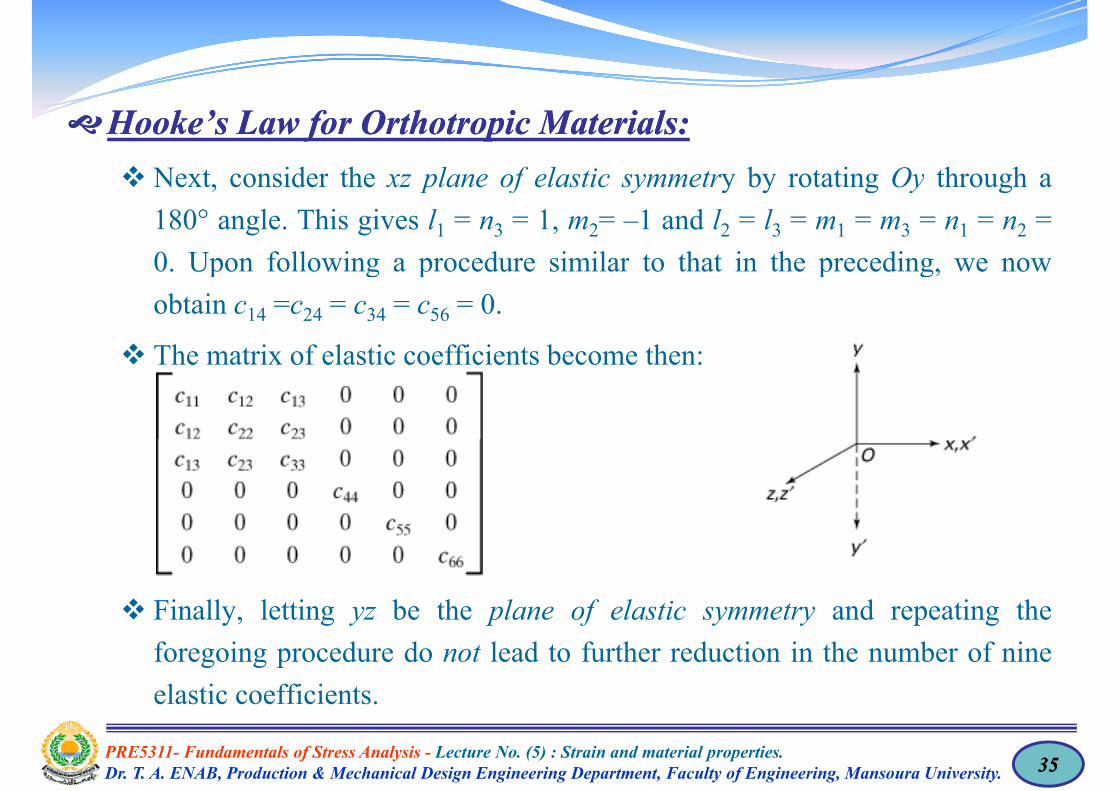
Hooke’sHooke’s LawLaw forfor OrthotropicOrthotropic MaterialsMaterials:: Next consider the xz plane of elastic symmetry by rotating Oy through a Next, consider the xz plane of elastic symmetry by rotating Oy through a180° angle. This gives l1 = n3 = 1, m2= –1 and l2 = l3 = m1 = m3 = n1 = n2 =0 Upon following a procedure similar to that in the preceding we now0. Upon following a procedure similar to that in the preceding, we nowobtain c14 =c24 = c34 = c56 = 0.
The matri of elastic coefficients become then: The matrix of elastic coefficients become then:
Finally letting yz be the plane of elastic symmetry and repeating the Finally, letting yz be the plane of elastic symmetry and repeating theforegoing procedure do not lead to further reduction in the number of nineelastic coefficients.
PRE5311- Fundamentals of Stress Analysis - Lecture No. (5) : Strain and material properties.Dr. T. A. ENAB, Production & Mechanical Design Engineering Department, Faculty of Engineering, Mansoura University. 3535
elastic coefficients.

Hooke’sHooke’s LawLaw forfor OrthotropicOrthotropic MaterialsMaterials:: Hence the generalized Hooke’s law for the most general orthotropic elastic Hence, the generalized Hooke s law for the most general orthotropic elasticmaterial is given by:
PRE5311- Fundamentals of Stress Analysis - Lecture No. (5) : Strain and material properties.Dr. T. A. ENAB, Production & Mechanical Design Engineering Department, Faculty of Engineering, Mansoura University. 3636

Hooke’sHooke’s LawLaw forfor OrthotropicOrthotropic MaterialsMaterials:: The inversed form of the above Eqs may be expressed in terms of The inversed form of the above Eqs. may be expressed in terms oforthotropic moduli and orthotropic Poisson’s ratios as follows:
PRE5311- Fundamentals of Stress Analysis - Lecture No. (5) : Strain and material properties.Dr. T. A. ENAB, Production & Mechanical Design Engineering Department, Faculty of Engineering, Mansoura University. 3737
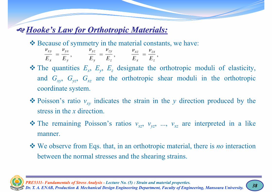
Hooke’sHooke’s LawLaw forfor OrthotropicOrthotropic MaterialsMaterials:: Because of symmetry in the material constants we have: Because of symmetry in the material constants, we have:
The quantities Ex, Ey, Ez designate the orthotropic moduli of elasticity,and Gxy, Gyz, Gxz are the orthotropic shear moduli in the orthotropiccoordinate system.
Poisson’s ratio νxy indicates the strain in the y direction produced by thestress in the x direction.
The remaining Poisson’s ratios νxz, νyz, ..., νxz are interpreted in a likey
manner.
We observe from Eqs. that, in an orthotropic material, there is no interactionq , p ,between the normal stresses and the shearing strains.
PRE5311- Fundamentals of Stress Analysis - Lecture No. (5) : Strain and material properties.Dr. T. A. ENAB, Production & Mechanical Design Engineering Department, Faculty of Engineering, Mansoura University. 3838

PRE5311- Fundamentals of Stress Analysis - Lecture No. (5) : Strain and material properties.Dr. T. A. ENAB, Production & Mechanical Design Engineering Department, Faculty of Engineering, Mansoura University. 3939