fundamentals and application of chemical solution ... sanctis.pdffundamentals and application of...
TRANSCRIPT

Fundamentals and Application of Chemical Solution Techniques for Thin
Films Synthesis
Dr. Oscar de Sanctis
Laboratorio de materiales Cerámicos
IFIR – CONICET, FCEIyA - Universidad
Nacional de Rosario
ARGENTINA
Email: [email protected]

Thin Film Deposition (extrinsic)Physical Vapor Deposition (PVD) -Film is formed by atoms directly
transported from source to the substrate through gas phase
•Evaporation
•Thermal evaporation
•E-beam evaporation
•Sputtering•DC sputtering
•DC Magnetron sputterng
•RF sputtering
•Reactive PVD
Chemical Vapor Deposition (CVD) -Film is formed by chemical reaction on the surface of substrate
•Low-Pressure CVD (LPCVD)
•Plasma-Enhanced CVD (PECVD)•Atmosphere-Pressure CVD (APCVD)
•Metal-Organic CVD (MOCVD)
Chemical Solution Deposition (CSD) – Film is formed starting from a liquid film
Platting
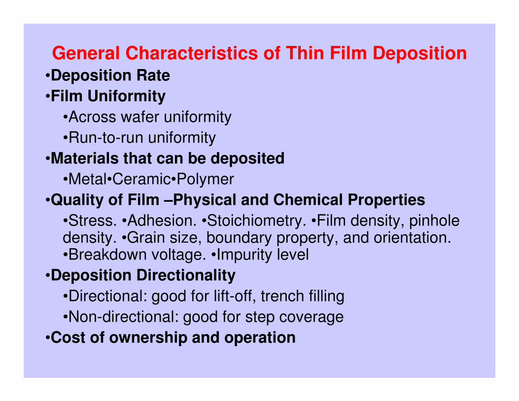
General Characteristics of Thin Film Deposition•Deposition Rate
•Film Uniformity
•Across wafer uniformity
•Run-to-run uniformity
•Materials that can be deposited
•Metal•Ceramic•Polymer
•Quality of Film –Physical and Chemical Properties
•Stress. •Adhesion. •Stoichiometry. •Film density, pinhole density. •Grain size, boundary property, and orientation. •Breakdown voltage. •Impurity level
•Deposition Directionality
•Directional: good for lift-off, trench filling
•Non-directional: good for step coverage
•Cost of ownership and operation

CVD Reactors1.) Atmospheric Pressure CVD (APCVD)
Advantages: High deposition rates, simple, high throughput
Disadvantages: Poor uniformity, purity is less than LPCVDUsed mainly for thick oxides.
2.) Low Pressure CVD (LPCVD at ~0.2 to 20 torr)
Advantages: Excellent uniformity, purityDisadvantages: Lower (but reasonable) deposition rates than APCVD
Used for polysilicon deposition, dielectric layer deposition, and doped dielectric deposition.
3.) Metal Organic CVD (MOCVD)Advantages.: Highly flexible—> can deposit semiconductors, metals,
dielectrics
Disadvantages: HIGHLY TOXIC!, Very expensive source material. Environmental disposal, costs are high.
4.) Plasma Enhance CVD. PE-MOD (Metal Organic Decomposition)
Plasmas are used to force reactions that would not be possible at low temperature.
Advantages.: Uses low temperatures necessary for rear end processing.
Disadvantages: Plasma damage typically results.Used for dielectrics coatings.

Chemical Solution Deposition (CSD) Processes
Synthesis of the precursor solution Liquid solution RT
Deposition on a substrate Liquid film RT
Drying film Hybrid amorphous film 100-200ºC
Burning of organic species Porous amorphous film 280-390ºC
Densification and crystallization Dense crystalline film 450-850ºC
Five basic stepsS
HR
INK
AG
E
——
——
——
——
—→→ →→
CSD collects all the processes that the precursor and the deposited film are liquid

Precursor Solution
The Preparation of multioxides materials precursor solution, such as perovskites, involves the use ofcation compounds that are dissolved in a common solvent
Several processes can be used for precursor solution preparation
Each process gives one characteristic precursor that
exhibit dramatic effect on the film properties
Simple processes consist in mixing soluble metal compounds in a common solvent where the precursor species retain a strong
resemblance to the starting.
More complex process are similar to a engineering molecular, tendering to synthesize precursors with structures similar to the final crystal structure of the desired perovskite film

FUNDAMENTS OF THE SOL-GEL
HORM(OR)-HO OHM(OR) 1-n2n +→+
Hydrolysis
Condensation: (water elimination)
OHM(OR)-O-M(RO)M(OR)-HOOH-M(RO) 21-n1n1-n1n +→+ −−
Oligomerization
1-n
(OR)(OR)(OR)
1n M(OR)MOMOM-O-M(RO)2-n2-n
2-n
−−−−−−
FORMATION OF THE GEL NETWORK

Characteristics SG process
• High water sensitive starting material
• Chemical bonding
• Different reaction ratio of metal precursors
• Poor control of molecular structure
• From lineal chain to 3-dimensional network
• Porous films
• Unstable solution
• High shrinkage

Zirconium n-
Propoxide
+ 2-Methoxyethanol
Lead Acetate
Trihydrate
+ 2 Methoxiethanol
Titanium
Ethoxide
+ 2-Methoxyethanol
Lead
precursor
(X)
Zirconium
precursor
(Y)
Titanium
precursor
(Z)
PZT
PRECURSOR
(W)
Alcohol
Exchange
(5 h, 124 ºC)
Alcohol
Exchange
(4 hs, 124 ºC)
Dehiydration
and alcoholysis
(10 hs, 124 ºC)
Complexation
(124ºC, 3 h)
( )3x-222 b(OEtOMe) 3)( OOCCHPMeOEtOHOHOAcPb →+⋅
Lead Precursor, Alcoholisis
Zirconium and Titanium Precursors, Alcohol exchangenn HOMeOEtOHOZr Pr4Zr(OEtOMe) 4)Pr( 44 +→+
HOEtMeOEtOHOEtTi 4Ti(OEtOMe) 4)( 44 +→+
High water sensitive starting material
Multi-metallic alkoxide
Precursor structure resembles to
the PZT perovskite lattice
Sol-Gel Process: 2- metoxyethanol Route
Common alkoxide group

OHOAcPb 22 3)( ⋅Lead Precursor
Zirconium and Titanium Precursors
Modified Sol-Gel Process
( )xn OOCCHHOAcOZr 3x-4
n)Zr(OPr )Pr( →+4
( )xOOCCHHOAcOEtTi 3x-4n)Ti(OPr )( →+4
Chelating agents: HOOCCH3 (Acetic acid) OR 2-4-pentanedione (ACAC)
SIMILAR PROCESS
LESS REACTIVITY
LESS STRUCTURECONTROL
Metal-Organic Decomposition: MOD
Precursors Solvent Long chain caboxylate
M(OOCCnHn+1 Xilene
Short chain
M(OOCCnHn+1
Alcohol
NO REACTIVITY AND NO
STRUCTURE

Chelate route
Starting materials• Chelating agents: Diethanolamine, ,Triethanolamine,
3-Hydroxy-2-butanone (Acetoin). • (n-1) or (n-2) non hydrolyzing metal precursor soluble
in alcohol. Nitrates or acetates. • One or two metal alkoxides.• Short chain alcohol solvent
•Low temperature burning residual organic groups (<450 ºC).
•Very low content of hydroxyls residual
•Onset of crystallization at lower temperature

PROCESS Simplicity Reactivityreactants
Organic residue
Shrinkage
Structurecontrol
OtherParameter
control
Stableprecursor
Nitrates Very High
None Very low None None Very high
Citrate/Nitrate Very High
None Very low None None High
Pechini/Nitrate High Low None ThicknessTexture
High
MOD Medium Low Very High None None High
Chelate route Medium Low Very Low Low ThicknessTexture
High
Modified Sol-gel Low High High Medium ThicknessTexture
Low
Sol-gel Very low Very high Medium High Thickness Very low
PROCESSES FOR PRECURSOR SOLUTION PREPARATION

DIP COATING
n
lρg
Vµt
∝

SPIN COATING
Step 2: the substrate is accelerated up to its final rotation speed. Aggressive fluid expulsion from the wafer
Step 3: the substrate is spinning at a constant rate and fluid viscous forces dominate fluid thinning behaviour. Possible starting of evaporation for volatile solvent
Step 1: is the deposition of the coating fluid onto the wafer or substrate.

• Solution viscosity
• Solid content
• Angular speed
• Spin Time
SPIN COATING
PARAMETERS

SPIN COATING DEFECTS
Film too thinSpin speed too high. Select lower speedSpin time too long. Decrease time during high speed stepInappropriate precursor solution
Film too thickSpin speed too low. Select higher speedSpin time too short. Increase time during high speed stepInappropriate precursor solution. To dilute solution

• Air bubbles on wafer surface
• Air bubbles in dispensed fluid
• Dispense tip is cut unevenly or has burrs or defects
Comets, streaks or flaresFluid velocity (dispense rate) is too highSpin bowl exhaust rate is too highResist sits on wafer too long prior to spinSpin speed and acceleration setting is too highParticles exist on substrate surface prior to dispenseFluid is not being dispensed at the centerof the substrate surface

Swirl patternSpin bowl exhaust rate is too highFluid is striking substrate surface off centerSpin speed and acceleration setting is too highSpin time too short
Uncoated AreasInsufficient Dispense Volume.Non uniform wetting
PinholesAir bubblesParticles in fluid. Solution filtrationParticles exist on substrate surface prior to dispense. Substrate cleaning

As-prepared film
BURNING
ORGANIC
GROUPS
Low porous Amorphous film
High porous Amorphous film

Densification and Crystallization
The film microstructure and orientation
depends from:
�The substrate and Solution chemistry,
�Material composition and crystallization
path
�Sequence and temperatures of the thermal
treatment.

Densification
Porous and Amorphous
Crystalline film
Sintering Crystallization
Mechanisms of Sintering
Condensation Reaction
Structural relaxation
Viscous flow
Solid state reaction
→
→
→
→
TEM
PER
AT
UR
E
HEATING RATE Sintering Mechanics
Densification
Low Consecutive Lower
High Concurrent Higher

Phase transitionPhase transition

2
20
G
x
∂>
∂2
20
G
x
∂<
∂

CrystallizationFilm crystallization in solution-derived thin films performs by a nucleation-and-growth process. The theoretical picture is parallel to that of glasses crystallization.
Path A: FerroelAmorhCa
G→
∆
→
PZT amorph→Pyrochlore→PZT perovkite
Path B:
FerroelInterdAmorhCiia
GG→→
∆∆
→→
SrTiO3 amorph → SrTiO3 Feroel

Nucleation
Volume free energy change (∆Ga→c) drives
Surface energy, ∆GS counter-drives
γ: interfacial energy crystalline – amorphous),
γππ 23 43/4 rGrG ca +∆=∆ →
caGr
→∆−=
γ2*
caGG
→∆=∆
πγ
3
16*
Nucleus growth
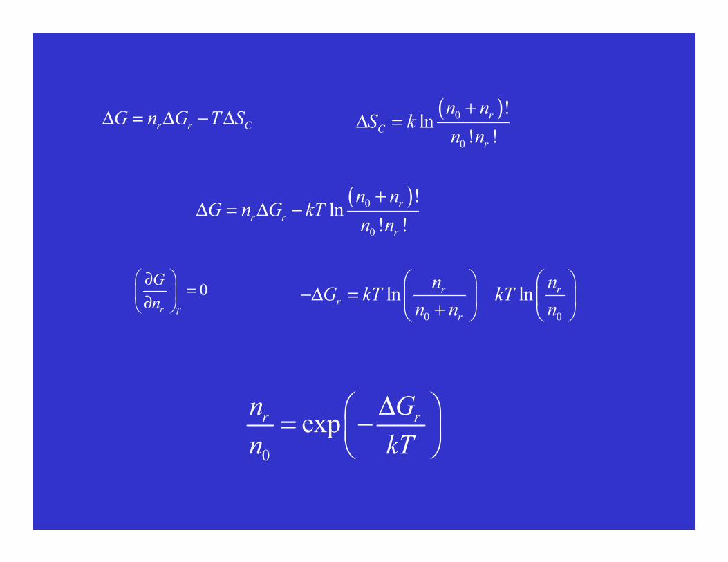
r r CG n G T S∆ = ∆ − ∆ ( )0
0
!ln
! !
r
C
r
n nS k
n n
+∆ =
( )0
0
!ln
! !
r
r r
r
n nG n G kT
n n
+∆ = ∆ −
0 0
ln lnr rr
r
n nG kT kT
n n n
−∆ =
+ �0
r T
G
n
∂=
∂
0
expr rn G
n kT
∆ = −

ac
ScSa
γ
γγθ
−=cos
Homogeneous vs Heterogeneous Nucleation
θθθθ: contact angleγγγγSa: substrate – amorphous interfacial energy
γγγγSc: substrate – crystalline interfacial energy
γγγγSa: amorphous – crystalline interfacial energy
( )4
12 2)cos)(cos( θθθ
−+=f( ) **
HOMOHETE GfG ∆=∆ θ
0º≤θ≤≤θ≤≤θ≤≤θ≤180º 1 ≥≥≥≥cosθ≥θ≥θ≥θ≥-1 0 ≤≤≤≤ f(θθθθ)≤≤≤≤1
Full wetting θθθθ=0 f(θθθθ)=0 ∆∆∆∆G*HETER=0
No wetting θθθθ=180º f(θθθθ)=1 ∆∆∆∆G*HETER=∆∆∆∆G*HOMO
SUBSTRATE SUBSTRATE
Random Polycrystalline film Oriented columnar film

Nucleation rate
−=kT
Eaexp0νν Collision frequency at interface nucleus,
Ea: atomic movement activation energy
−
∆−=
kT
E
kT
GnnN aS expexp
*
00ν

RATE
FavorsNucleation
Conventional < 100 ºC/min At low
Temperature
RTA > 1000 ºC/min At high Temperature
Effects of the Heat Treatment on the Nucleation

PROBLEMIn ferroelectric capacitors built with films of BaTiO3 (BT), PbZr0.2Ti0.8O3 (PZT) and SrBi2Ta2O9 (SBT) and electrode Pt. What heat treatment would develop the appropriated microstructure that produce the maximum remanet polarization
→
→
→
→
→
→
→
→
←
→←
→
←
→←
→
Gro
wth
[[ [[0
01
]] ]]
Gro
wth
[[ [[001
]] ]]
Po
lari
zati
on
[[ [[00
1]] ]]
←→←→←→←→
Polarization [[[[110]]]]
Pt
BT and PZTSBT
Pt
BT Amorphous →→→→ BT crystalline
PATHS PZT Amorphous →→→→ pyrochlore →→→→ PZT crystalline
SBT Amorphous →→→→ Fluorite SBT →→→→ perovskite SBT

SUBSTRATE
FILM

XPS SiO2 film on AISI 304Thermal treatment 700 ºC for 1 hours
exp aE
RTν
∝ −
Interdiffusion Structural effect
INTERACCION FILM-SUBSTRATE
Thermal Activated Process
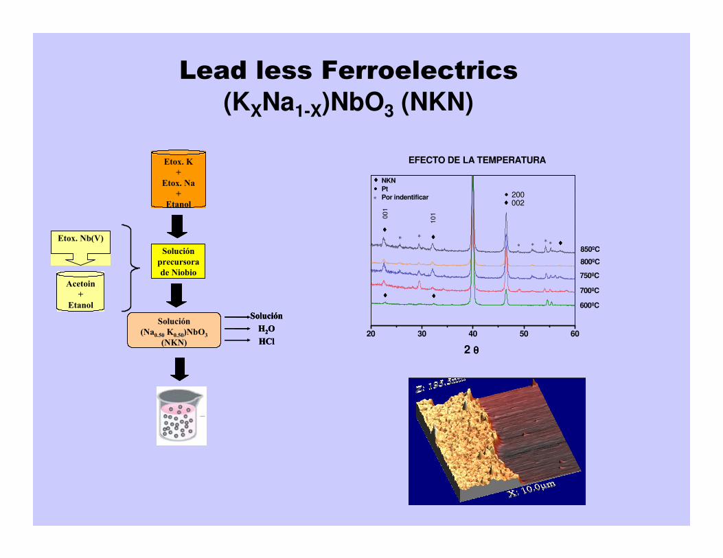
Lead less Ferroelectrics
(KXNa1-X)NbO3 (NKN)
Acetoin
+
Etanol
Etox. Nb(V)
Solución
precursora
de Niobio
Etox. K
+
Etox. Na
+
Etanol
Solución
(Na0.50 K0.50)NbO3
(NKN)
Solución
H2O
HCl
Acetoin
+
Etanol
Etox. Nb(V)
Acetoin
+
Etanol
Etox. Nb(V)
Solución
precursora
de Niobio
Solución
precursora
de Niobio
Etox. K
+
Etox. Na
+
Etanol
Solución
(Na0.50 K0.50)NbO3
(NKN)
Solución
H2O
HCl
Solución
H2O
HCl20 30 40 50 60
♦♦♦♦
♦♦♦♦∗∗∗
∗
••••
∗
∗
∗
••••
♦♦♦♦
♦♦♦♦♦♦♦♦
♦♦♦♦
600ºC
850ºC
800ºC
700ºC
2 θθθθ
750ºC
EFECTO DE LA TEMPERATURA
♦♦♦♦
NKN
Pt
Por indentificar
00
1
10
1
002200