functional safety manual - automation solutions rosem… · · 2015-04-08functional safety...
TRANSCRIPT

Manual Supplement00809-0500-4130, Rev AG
March 2015
Rosemount 2130Functional Safety Manual

Manual Supplement00809-0500-4130, Rev AG
ContentsMarch 2015
Contents 1Section 1: Introduction
1.1 Scope and purpose of the safety manual . . . . . . . . . . . . . . . . . . . . . . . . . . . . . . . . . . 1
1.2 Skill level requirement . . . . . . . . . . . . . . . . . . . . . . . . . . . . . . . . . . . . . . . . . . . . . . . . . . 1
1.3 Terms, abbreviations, and acronyms . . . . . . . . . . . . . . . . . . . . . . . . . . . . . . . . . . . . . . 1
1.4 Documentation and standards . . . . . . . . . . . . . . . . . . . . . . . . . . . . . . . . . . . . . . . . . . . 3
2Section 2: Product Description2.1 Operation principle . . . . . . . . . . . . . . . . . . . . . . . . . . . . . . . . . . . . . . . . . . . . . . . . . . . . . 5
2.2 Level switch purpose . . . . . . . . . . . . . . . . . . . . . . . . . . . . . . . . . . . . . . . . . . . . . . . . . . . . 5
2.3 Ordering information . . . . . . . . . . . . . . . . . . . . . . . . . . . . . . . . . . . . . . . . . . . . . . . . . . . 6
3Section 3: Designing a Safety Function using the Rosemount 21303.1 Safety function . . . . . . . . . . . . . . . . . . . . . . . . . . . . . . . . . . . . . . . . . . . . . . . . . . . . . . . . . 7
3.2 Environmental limits . . . . . . . . . . . . . . . . . . . . . . . . . . . . . . . . . . . . . . . . . . . . . . . . . . . . 7
3.3 Application limits . . . . . . . . . . . . . . . . . . . . . . . . . . . . . . . . . . . . . . . . . . . . . . . . . . . . . . . 7
3.4 Design verification. . . . . . . . . . . . . . . . . . . . . . . . . . . . . . . . . . . . . . . . . . . . . . . . . . . . . . 7
3.5 SIL capability . . . . . . . . . . . . . . . . . . . . . . . . . . . . . . . . . . . . . . . . . . . . . . . . . . . . . . . . . . . 8
3.5.1 Systematic integrity . . . . . . . . . . . . . . . . . . . . . . . . . . . . . . . . . . . . . . . . . . . . . 8
3.5.2 Random integrity. . . . . . . . . . . . . . . . . . . . . . . . . . . . . . . . . . . . . . . . . . . . . . . . 8
3.5.3 Safety parameters . . . . . . . . . . . . . . . . . . . . . . . . . . . . . . . . . . . . . . . . . . . . . . . 8
3.6 Connection of the 2130 to the SIS logic solver. . . . . . . . . . . . . . . . . . . . . . . . . . . . . . 9
3.7 General requirements . . . . . . . . . . . . . . . . . . . . . . . . . . . . . . . . . . . . . . . . . . . . . . . . . . . 9
4Section 4: Installation and Commissioning4.1 Installation . . . . . . . . . . . . . . . . . . . . . . . . . . . . . . . . . . . . . . . . . . . . . . . . . . . . . . . . . . .11
4.2 Physical location and placement. . . . . . . . . . . . . . . . . . . . . . . . . . . . . . . . . . . . . . . . .11
4.3 Electrical connections . . . . . . . . . . . . . . . . . . . . . . . . . . . . . . . . . . . . . . . . . . . . . . . . . .11
4.4 Configuration . . . . . . . . . . . . . . . . . . . . . . . . . . . . . . . . . . . . . . . . . . . . . . . . . . . . . . . . .11
4.4.1 Self-check setting . . . . . . . . . . . . . . . . . . . . . . . . . . . . . . . . . . . . . . . . . . . . . . 11
4.4.2 Output mode setting . . . . . . . . . . . . . . . . . . . . . . . . . . . . . . . . . . . . . . . . . . . 12
5Section 5: Operation and Maintenance5.1 Proof-test requirement. . . . . . . . . . . . . . . . . . . . . . . . . . . . . . . . . . . . . . . . . . . . . . . . .13
5.2 Repair and replacement . . . . . . . . . . . . . . . . . . . . . . . . . . . . . . . . . . . . . . . . . . . . . . . .13
5.3 Notification of failures. . . . . . . . . . . . . . . . . . . . . . . . . . . . . . . . . . . . . . . . . . . . . . . . . .13
iiiContents
Manual Supplement00809-0500-4130, Rev AG
ContentsMarch 2015
6Appendix A: SpecificationsA.1 General . . . . . . . . . . . . . . . . . . . . . . . . . . . . . . . . . . . . . . . . . . . . . . . . . . . . . . . . . . . . . .15
A.2 Useful life. . . . . . . . . . . . . . . . . . . . . . . . . . . . . . . . . . . . . . . . . . . . . . . . . . . . . . . . . . . . .15
A.3 Useful lifetime . . . . . . . . . . . . . . . . . . . . . . . . . . . . . . . . . . . . . . . . . . . . . . . . . . . . . . . .16
7Appendix B: Proposed Proof-test ProcedureB.1 Suggested proof-test . . . . . . . . . . . . . . . . . . . . . . . . . . . . . . . . . . . . . . . . . . . . . . . . . .17
8Appendix C: Product IdentificationC.1 Approved cassette part numbers . . . . . . . . . . . . . . . . . . . . . . . . . . . . . . . . . . . . . . . .19
iv Contents
Manual Supplement00809-0500-4130, Rev AG
Section 1: IntroductionMarch 2015
Section 1 Introduction
1.1 Scope and purpose of the safety manual
This safety manual contains the information to design, install, verify and maintain a Safety Instrumented Function (SIF) utilizing the Rosemount 2130 level switch.
The manual provides the necessary requirements to enable the integration of the 2130 level switch when showing compliance with the IEC 61508 or IEC 61511 functional safety standards. It indicates all assumptions that have been made on the usage of the Level Switch. If these assumptions cannot be met by the application, the SIL capability of the Rosemount 2130 may be adversely affected.
NoteFor product support, use the contact details on the back page.
1.2 Skill level requirement
System design, installation and commissioning, and repair and maintenance shall be carried out by suitably qualified personnel.
1.3 Terms, abbreviations, and acronyms
Basic Safety
Freedom from unacceptable risk of harm.
BPCS
Basic Process Control System – a system which responds to input signals from the process, its associated equipment, other programmable systems and/or an operator and generates output signals causing the process and its associated equipment to operate in the desired manner but which does not perform any safety instrumented functions with a claimed SIL greater than or equal to 1.
Fail-safe State
State where switch output is in the state corresponding to an alarm condition. In this condition the switch contacts will normally be open.
Fail Dangerous
Failure that does not respond to an input from the process (i.e. not switching to the fail-safe state).
Fail Dangerous Detected
Failure that is dangerous but is detected.
1Introduction

Manual Supplement00809-0500-4130, Rev AG
Section 1: IntroductionMarch 2015
Fail Dangerous Undetected
Failure that is dangerous and that is not detected.
Fail No Effect
Failure of a component that is part of the safety function but that has no effect on the safety function.
Fail Safe
Failure that causes the switch to go to the defined fail-safe state without an input from the process.
FMEDA
Failure Modes, Effects, and Diagnostics Analysis.
Functional Safety
Part of the overall safety relating to the process and the BPCS which depends on the correct functioning of the SIS and other protection layers.
HFT
Hardware Fault Tolerance.
Low demand
Mode of operation, where the frequency of demands for operation made on a safety-related system is no greater than twice the proof test frequency.
PFDAVG
Average Probability of Failure on Demand.
SFF
Safe Failure Fraction – a fraction of the overall random failure rate of a device that results in either a safe failure or a detected dangerous failure.
SIF
Safety Instrumented Function – a safety function with a specified SIL which is necessary to achieve functional safety. Typically a set of equipment intended to reduce the risk due to a specified hazard (a safety loop).
SIL
Safety Integrity Level – a discrete level (one out of four) for specifying the safety integrity requirements of the safety instrumented functions to be allocated to the safety instrumented systems. SIL 4 has the highest level of safety integrity, and SIL 1 has the lowest level.
2 Introduction

Manual Supplement00809-0500-4130, Rev AG
Section 1: IntroductionMarch 2015
SIS
Safety Instrumented System – an instrumented system used to implement one or more safety instrumented functions. An SIS is composed of any combination of sensors, logic solvers, and final elements.
1.4 Documentation and standards
This section lists the documentation and standards referred to by this safety manual.
Table 1-1. Associated Documentation
Table 1-2. Associated Standards
Documents Purpose of Documents
IEC 61508-2: 2000 Functional Safety of Electrical/Electronic/Programmable Electronic Safety-Related Systems
MOB 08/08-57 R005 FMEDA Report Version V1, Revision R5 for the Rosemount 2130 Level Switch
00813-0100-4130 Rosemount 2130 Product Data Sheet
00809-0100-4130 Rosemount 2130 Reference Manual
Standards Purpose of Standards
IEC 61508: 2000 Functional Safety of electrical/electronic/programmable electronic safety-related systems
IEC 61511(ANSI/ISA 84.00.01-2004)
Functional safety - Safety instrumented systems for the process industry sector
3Introduction

Manual Supplement00809-0500-4130, Rev AG
Section 1: IntroductionMarch 2015
4 Introduction
Manual Supplement00809-0500-4130, Rev AG
Section 2: Product DescriptionMarch 2015
Section 2 Product Description
2.1 Operation principle
The Rosemount 2130 level switch consists of a tuned fork with a driver and receiver element, and integral interface electronics. The 2130 level switch is based on the principle that the resonant frequency of a tuned fork changes when it is immersed in a liquid. The frequency change is detected and used to switch an electronic output.
A range of output options are available to suit different applications.
NoteFor all product information and documentation downloads, visit www.rosemount.com.
2.2 Level switch purpose
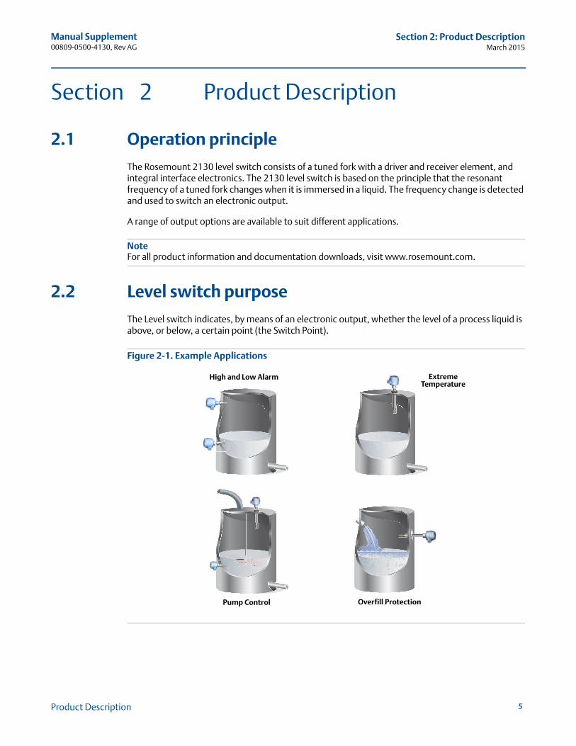
The Level switch indicates, by means of an electronic output, whether the level of a process liquid is above, or below, a certain point (the Switch Point).
Figure 2-1. Example Applications
High and Low Alarm
Overfill ProtectionPump Control
ExtremeTemperature
5Product Description
Manual Supplement00809-0500-4130, Rev AG
Section 2: Product DescriptionMarch 2015
6
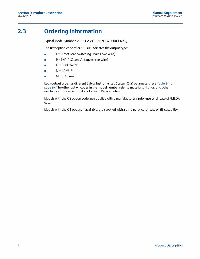
2.3 Ordering information
Typical Model Number: 2130 L A 2 E S 9 NN B A 0000 1 NA QT
The first option code after “2130” indicates the output type:
L = Direct Load Switching (Mains two-wire)
P = PNP/PLC Low Voltage (three-wire)
D = DPCO Relay
N = NAMUR
M = 8/16 mA
Each output type has different Safety Instrumented System (SIS) parameters (see Table 3-1 on page 9). The other option codes in the model number refer to materials, fittings, and other mechanical options which do not affect SIS parameters.
Models with the QS option code are supplied with a manufacturer’s prior-use certificate of FMEDA data.
Models with the QT option, if available, are supplied with a third party certificate of SIL capability.
Product Description
Manual Supplement00809-0500-4130, Rev AG
Section 3: Designing a Safety Function using the Rosemount 2130March 2015
Section 3 Designing a Safety Function using the Rosemount 2130
3.1 Safety function
A change in liquid level through the switch point of the Rosemount 2130 level switch causes it to operate. It may be used in high level or low level safety related applications. It is important that the 2130 is user-configured for the correct application.
3.2 Environmental limits
The designer of the SIF (Safety Instrumented Function) must check that the Rosemount 2130 level switch is rated for use within the expected environmental limits. See the Rosemount 2130 product data sheet for environmental limits.
NoteFor all product information and documentation downloads, see the on-lineRosemount 2130 web page at www.rosemount.com.
3.3 Application limits
It is very important that the SIF designer checks for material compatibility by considering process liquids and on-site chemical contaminants. If the Rosemount 2130 level switch is used outside the application limits or with incompatible materials, the reliability data and predicted SIL capability becomes invalid.
The construction materials of a Rosemount 2130 level switch are specified in the product data sheet and the product reference manual (see Table 1-1 on page 3). Use the model code on the product label, and the ordering information table and specification in these product documents to find out the construction materials.
3.4 Design verification
A detailed Failure Modes, Effects and Diagnostics Analysis (FMEDA) report for the Rosemount 2130 is available from Emerson Process Management. This report details all failure rates and failure modes as well as expected lifetime.
NoteThe FMEDA report is available from the Safety quick link at www.rosemount.com. Select Product List, then Level tab, and finally select 2130. In the right-hand panel, there are SIL documents including the FMEDA report (and this safety manual).
The achieved Safety Integrity Level (SIL) of an entire Safety Instrumented Function (SIF) design must be verified by the designer using a PFDAVG calculation considering the architecture, proof test interval, proof test effectiveness, any automatic diagnostics, average repair time, and the specific failures rates of all equipment included in the SIF.
7Designing a Safety Function using the Rosemount 2130
Manual Supplement00809-0500-4130, Rev AG
Section 3: Designing a Safety Function using the Rosemount 2130March 2015
Each subsystem must be checked to assure compliance with minimum Hardware Fault Tolerance (HFT) requirements. When using the Rosemount 2130 level switch in a redundant configuration, a common cause factor of at least 5% should be included in the safety integrity calculations.
The failure rate data listed in the FMEDA report is only valid for the useful lifetime of the Rosemount 2130. The failure rates increase after this useful lifetime period has expired. Reliability calculations based on the data listed in the FMEDA report for mission times beyond the lifetime may yield results that are too optimistic, i.e. the calculated SIL will not be achieved.
3.5 SIL capability
3.5.1 Systematic integrity
The 2130 level switch has met manufacturer design process requirements ofSafety Integrity Level 2 (SIL 2). These are intended to achieve sufficient integrity against systematic errors of design by the manufacturer.
A Safety Instrumented Function (SIF) designed with the 2130 must not be used at a SIL higher than the statement without “prior use” justification by the end-user, or verification of diverse technology in the design.
3.5.2 Random integrity
The 2130 level switch is classified as a type B device according to IEC 61508, and the level switch has a Hardware Fault Tolerance (HFT) of zero.
Random Integrity for Type B device:
Output Types N, P, and L: SIL 2 @ HFT=0
Output Type D: SIL 1 @ HFT=0, SIL 2 @ HFT=1
3.5.3 Safety parameters
Table 3-1 on page 9 summarizes the Rosemount 2130 failure rates. For detailed failure rate information, including PFDAVG and MTTR data, see the FMEDA report for the Rosemount 2130.
8 Designing a Safety Function using the Rosemount 2130
Manual Supplement00809-0500-4130, Rev AG
Section 3: Designing a Safety Function using the Rosemount 2130March 2015
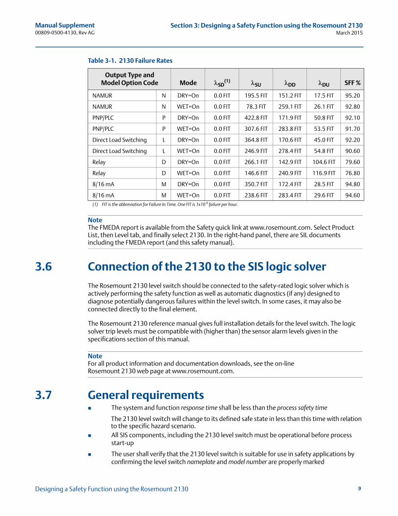
Table 3-1. 2130 Failure Rates
NoteThe FMEDA report is available from the Safety quick link at www.rosemount.com. Select Product List, then Level tab, and finally select 2130. In the right-hand panel, there are SIL documents including the FMEDA report (and this safety manual).
3.6 Connection of the 2130 to the SIS logic solver
The Rosemount 2130 level switch should be connected to the safety-rated logic solver which is actively performing the safety function as well as automatic diagnostics (if any) designed to diagnose potentially dangerous failures within the level switch. In some cases, it may also be connected directly to the final element.
The Rosemount 2130 reference manual gives full installation details for the level switch. The logic solver trip levels must be compatible with (higher than) the sensor alarm levels given in the specifications section of this manual.
NoteFor all product information and documentation downloads, see the on-lineRosemount 2130 web page at www.rosemount.com.
3.7 General requirements The system and function response time shall be less than the process safety time
The 2130 level switch will change to its defined safe state in less than this time with relation to the specific hazard scenario.
All SIS components, including the 2130 level switch must be operational before process start-up
The user shall verify that the 2130 level switch is suitable for use in safety applications by confirming the level switch nameplate and model number are properly marked
Output Type andModel Option Code Mode SD
(1)
(1) FIT is the abbreviation for Failure In Time. One FIT is 1x10⁻⁹ failure per hour.
SU DD DU SFF %
NAMUR N DRY=On 0.0 FIT 195.5 FIT 151.2 FIT 17.5 FIT 95.20
NAMUR N WET=On 0.0 FIT 78.3 FIT 259.1 FIT 26.1 FIT 92.80
PNP/PLC P DRY=On 0.0 FIT 422.8 FIT 171.9 FIT 50.8 FIT 92.10
PNP/PLC P WET=On 0.0 FIT 307.6 FIT 283.8 FIT 53.5 FIT 91.70
Direct Load Switching L DRY=On 0.0 FIT 364.8 FIT 170.6 FIT 45.0 FIT 92.20
Direct Load Switching L WET=On 0.0 FIT 246.9 FIT 278.4 FIT 54.8 FIT 90.60
Relay D DRY=On 0.0 FIT 266.1 FIT 142.9 FIT 104.6 FIT 79.60
Relay D WET=On 0.0 FIT 146.6 FIT 240.9 FIT 116.9 FIT 76.80
8/16 mA M DRY=On 0.0 FIT 350.7 FIT 172.4 FIT 28.5 FIT 94.80
8/16 mA M WET=On 0.0 FIT 238.6 FIT 283.4 FIT 29.6 FIT 94.60
9Designing a Safety Function using the Rosemount 2130
Manual Supplement00809-0500-4130, Rev AG
Section 3: Designing a Safety Function using the Rosemount 2130March 2015
Personnel performing maintenance and testing on the 2130 level switch shall first be assessed as being competent to do so
Results from periodic proof tests shall be recorded and periodically reviewed
The 2130 level switch shall not be operated beyond the useful lifetime as listed in the specification section of the product reference manual without undergoing overhaul or replacement
NoteFor all product information and documentation downloads, see the on-lineRosemount 2130 web page at www.rosemount.com.
10 Designing a Safety Function using the Rosemount 2130
Manual Supplement00809-0500-4130, Rev AG
Section 4: Installation and CommissioningMarch 2015
Section 4 Installation and Commissioning
NoteFor all product information and documentation downloads, see the on-lineRosemount 2130 web page at www.rosemount.com.
4.1 Installation
The Rosemount 2130 level switch must be installed as described in the installation section of the product reference manual. Check that environmental conditions do not exceed the ratings in the specification section.
The 2130 level switch must be accessible for physical inspection.
4.2 Physical location and placement
The Rosemount 2130 level switch shall be accessible with sufficient room for cover removal and electrical connections, and allow for manual proof-testing to take place.
The switch point is determined by the location of the 2130 level switch, and consideration must be given to allow the safe proof-testing of the level switch by forcing liquid to put the switch into its Fail-Safe state.
4.3 Electrical connections
Wiring should be adequately rated and not be susceptible to mechanical damage.Electrical conduit is commonly used to protect wiring.
4.4 Configuration
4.4.1 Self-check setting
The Rosemount 2130 level switch must be user-configured to operate in the Self-check mode. This mode enables the internal diagnostic routines.
Self-check mode is indicated by the amber color of the LED on the electronics cassette. SIS-certified 2130 level switches (dependent on model code) are shipped with this mode pre-configured, but must be checked before first use, and periodically thereafter, as part of the proof-test routine.
11Installation and Commissioning
Manual Supplement00809-0500-4130, Rev AG
Section 4: Installation and CommissioningMarch 2015
12
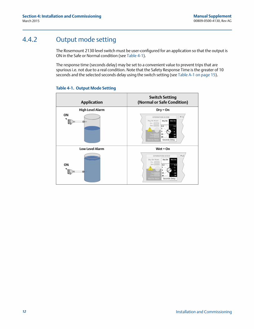
4.4.2 Output mode setting
The Rosemount 2130 level switch must be user-configured for an application so that the output is ON in the Safe or Normal condition (see Table 4-1).
The response time (seconds delay) may be set to a convenient value to prevent trips that are spurious i.e. not due to a real condition. Note that the Safety Response Time is the greater of 10 seconds and the selected seconds delay using the switch setting (see Table A-1 on page 15).
Table 4-1. Output Mode Setting
ApplicationSwitch Setting
(Normal or Safe Condition)
High Level Alarm Dry = On
Low Level Alarm Wet = On
ONOPERATION MODE
Dryrr On ModeDryrrWet
Wet On Mode
DryrWet
Dry On Wet On
Seconds Delay
0.3 0.3
3
3010
1
3
3010
1
PLCCCCC
ON
OPERATION MODE
Dryrr On ModeDryrrWet
Wet On Mode
DryrWet
Dry On Wet On
Seconds Delay
0.3 0.3
3
3010
1
3
3010
1
PLCCCCC
Installation and Commissioning
Manual Supplement00809-0500-4130, Rev AG
Section 5: Operation and MaintenanceMarch 2015
Section 5 Operation and Maintenance
5.1 Proof-test requirement
During operation, a low-demand mode SIF must be proof-tested. The objective of proof-testing is to detect failures within the equipment in the SIF that are not detected by any automatic diagnostics of the system. Undetected failures that prevent the SIF from performing its function are the main concern.
Periodic proof-tests shall take place at the frequency (or interval) defined by the SIL verification calculation. The proof-tests must be performed more frequently than or as frequently as specified in the SIL verification calculation in order to maintain the required safety integrity of the overall SIF.A sample procedure is provided in Appendix B: Proposed Proof-test Procedure.
Results from periodic proof tests shall be recorded and periodically reviewed.
5.2 Repair and replacement
Repair procedures in the Rosemount 2130 level switch reference manual must be followed.
5.3 Notification of failures
In case of malfunction of the system or SIF, the Rosemount 2130 level switch shall be put out of operation and the process shall be kept in a safe state by other measures.
Emerson Process Management must be informed when the Rosemount 2130 level switch is required to be replaced due to failure. The occurred failure shall be documented and reported to Emerson Process Management using the contact details on the back page of this safety manual. This is an important part of Emerson Process Management’s SIS management process.
13Operation and Maintenance
Manual Supplement00809-0500-4130, Rev AG
Section 5: Operation and MaintenanceMarch 2015
14 Operation and Maintenance
Manual Supplement00809-0500-4130, Rev AG
Appendix A: SpecificationsMarch 2015
Appendix A Specifications
A.1 General
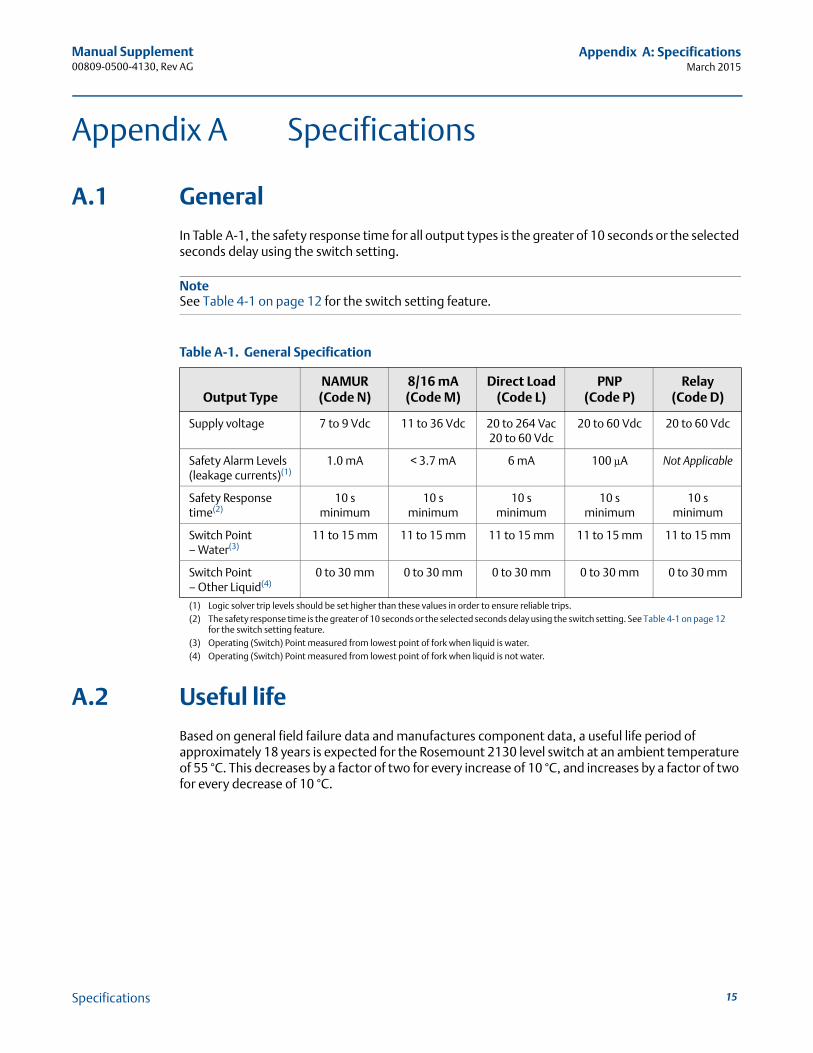
In Table A-1, the safety response time for all output types is the greater of 10 seconds or the selected seconds delay using the switch setting.
NoteSee Table 4-1 on page 12 for the switch setting feature.
Table A-1. General Specification
A.2 Useful life
Based on general field failure data and manufactures component data, a useful life period of approximately 18 years is expected for the Rosemount 2130 level switch at an ambient temperature of 55 °C. This decreases by a factor of two for every increase of 10 °C, and increases by a factor of two for every decrease of 10 °C.
Output TypeNAMUR
(Code N)8/16 mA (Code M)
Direct Load (Code L)
PNP(Code P)
Relay(Code D)
Supply voltage 7 to 9 Vdc 11 to 36 Vdc 20 to 264 Vac20 to 60 Vdc
20 to 60 Vdc 20 to 60 Vdc
Safety Alarm Levels(leakage currents)(1)
(1) Logic solver trip levels should be set higher than these values in order to ensure reliable trips.
1.0 mA < 3.7 mA 6 mA 100 μA Not Applicable
Safety Response time(2)
(2) The safety response time is the greater of 10 seconds or the selected seconds delay using the switch setting. See Table 4-1 on page 12 for the switch setting feature.
10 s minimum
10 sminimum
10 sminimum
10 sminimum
10 sminimum
Switch Point– Water(3)
(3) Operating (Switch) Point measured from lowest point of fork when liquid is water.
11 to 15 mm 11 to 15 mm 11 to 15 mm 11 to 15 mm 11 to 15 mm
Switch Point– Other Liquid(4)
(4) Operating (Switch) Point measured from lowest point of fork when liquid is not water.
0 to 30 mm 0 to 30 mm 0 to 30 mm 0 to 30 mm 0 to 30 mm
15Specifications

Manual Supplement00809-0500-4130, Rev AG
Appendix A: SpecificationsMarch 2015
A.3 Useful lifetime
According to Section 7.4.7.4 of the standard IEC 61508-2, a useful lifetime based on experience should be assumed.
Although a constant failure rate is assumed by the probabilistic estimation method (see FMEDA report), this only applies provided that the useful lifetime(1) of components is not exceeded. Beyond their useful lifetime, the result of the probabilistic calculation method is therefore meaningless as the probability of failure significantly increases with time.
The useful lifetime is highly dependent on the subsystem itself and its operating conditions. Specifically, the equipment contains electrolytic capacitors which have a useful life which is highly dependent on ambient temperature (see Safety Data in the FMEDA report).
This assumption of a constant failure rate is based on the bath-tub curve. Therefore, it is obvious that the PFDAVG calculation is only valid for components that have this constant domain and that the validity of the calculation is limited to the useful lifetime of each component.
It is the responsibility of the end-user to maintain and operate the Rosemount 2130 level switch according to the manufacturer's instructions. Furthermore, regular inspection should show that all components are clean and free from damage.
For high-demand mode applications, the useful lifetime of the mechanical parts is limited by the number of cycles. The useful lifetime of the mechanical and electrical parts is greater than 200000 operations. When plant experience indicates a shorter useful lifetime than indicated, the number based on plant experience should be used.
(1) Useful lifetime is a reliability engineering term that describes the operational time interval where the failure rate of a device is rela-tively constant. It is not a term which covers product obsolescence, warranty, or other commercial issues.
16 Specifications
Manual Supplement00809-0500-4130, Rev AG
Appendix B: Proposed Proof-test ProcedureMarch 2015
Appendix B Proposed Proof-test Procedure
B.1 Suggested proof-test
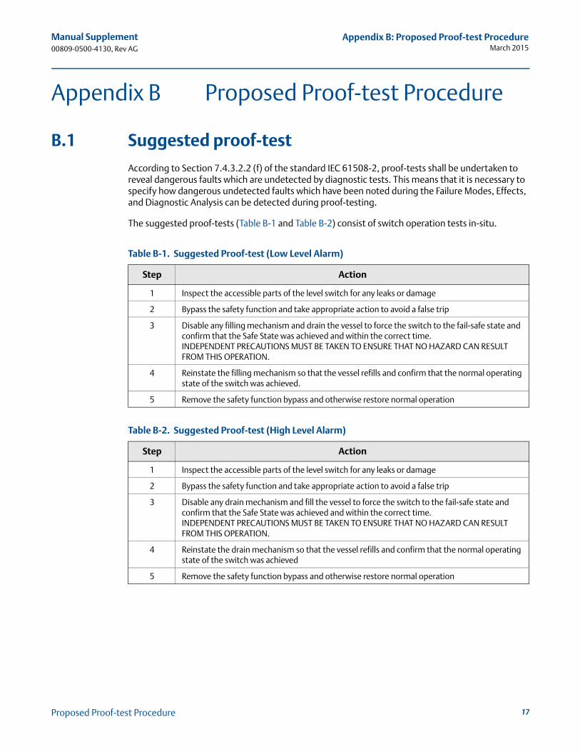
According to Section 7.4.3.2.2 (f) of the standard IEC 61508-2, proof-tests shall be undertaken to reveal dangerous faults which are undetected by diagnostic tests. This means that it is necessary to specify how dangerous undetected faults which have been noted during the Failure Modes, Effects, and Diagnostic Analysis can be detected during proof-testing.
The suggested proof-tests (Table B-1 and Table B-2) consist of switch operation tests in-situ.
Table B-1. Suggested Proof-test (Low Level Alarm)
Table B-2. Suggested Proof-test (High Level Alarm)
Step Action
1 Inspect the accessible parts of the level switch for any leaks or damage
2 Bypass the safety function and take appropriate action to avoid a false trip
3 Disable any filling mechanism and drain the vessel to force the switch to the fail-safe state and confirm that the Safe State was achieved and within the correct time.INDEPENDENT PRECAUTIONS MUST BE TAKEN TO ENSURE THAT NO HAZARD CAN RESULT FROM THIS OPERATION.
4 Reinstate the filling mechanism so that the vessel refills and confirm that the normal operating state of the switch was achieved.
5 Remove the safety function bypass and otherwise restore normal operation
Step Action
1 Inspect the accessible parts of the level switch for any leaks or damage
2 Bypass the safety function and take appropriate action to avoid a false trip
3 Disable any drain mechanism and fill the vessel to force the switch to the fail-safe state and confirm that the Safe State was achieved and within the correct time.INDEPENDENT PRECAUTIONS MUST BE TAKEN TO ENSURE THAT NO HAZARD CAN RESULT FROM THIS OPERATION.
4 Reinstate the drain mechanism so that the vessel refills and confirm that the normal operating state of the switch was achieved
5 Remove the safety function bypass and otherwise restore normal operation
17Proposed Proof-test Procedure
Manual Supplement00809-0500-4130, Rev AG
Appendix B: Proposed Proof-test ProcedureMarch 2015
18 Proposed Proof-test Procedure
Manual Supplement00809-0500-4130, Rev AG
Appendix C: Product IdentificationMarch 2015
Appendix C Product Identification
C.1 Approved cassette part numbers
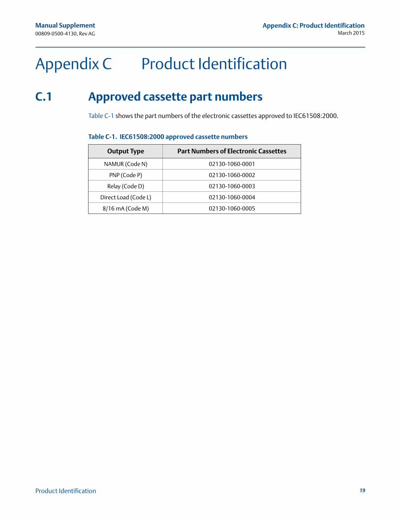
Table C-1 shows the part numbers of the electronic cassettes approved to IEC61508:2000.
Table C-1. IEC61508:2000 approved cassette numbers
Output Type Part Numbers of Electronic Cassettes
NAMUR (Code N) 02130-1060-0001
PNP (Code P) 02130-1060-0002
Relay (Code D) 02130-1060-0003
Direct Load (Code L) 02130-1060-0004
8/16 mA (Code M) 02130-1060-0005
19Product Identification

Manual Supplement00809-0500-4130, Rev AG
Appendix C: Product IdentificationMarch 2015
20 Product Identification

Manual Supplement00809-0500-4130, Rev AG
March 2015
Rosemount World Headquarters
Emerson Process Management 6021 Innovation BlvdShakopee, MN 55379, USA+1 800 999 9307 or +1 952 906 8888+1 952 949 7001 [email protected]
North America Regional OfficeEmerson Process Management 8200 Market Blvd.Chanhassen, MN 55317, USA
+1 800 999 9307 or +1 952 906 8888+1 952 949 7001 [email protected]
Latin America Regional OfficeEmerson Process Management 1300 Concord Terrace, Suite 400Sunrise, Florida, 33323, USA
+1 954 846 5030+1 954 846 [email protected]
Europe Regional OfficeEmerson Process Management Europe GmbHNeuhofstrasse 19a P.O. Box 1046CH 6340 BaarSwitzerland
+41 (0) 41 768 6111+41 (0) 41 768 6300 [email protected]
Asia Pacific Regional Office
Emerson Process Management Asia Pacific Pte Ltd1 Pandan CrescentSingapore 128461+65 6777 8211+65 6777 0947 [email protected]
Middle East and Africa Regional OfficeEmerson Process Management Emerson FZE P.O. Box 17033,Jebel Ali Free Zone - South 2Dubai, United Arab Emirates
+971 4 8118100+971 4 8865465 [email protected]
Standard Terms and Conditions of Sale can be found at: www.rosemount.com\terms_of_sale.The Emerson logo is a trademark and service mark of Emerson Electric Co.Rosemount and Rosemount logotype are registered trademarks of Rosemount Inc.All other marks are the property of their respective owners.© 2015 Rosemount\ Inc. All rights reserved.