•function units you have fully understood a technical
TRANSCRIPT

Bräunl 2021 1
CHAPTER 5 CPU Design
• Function Units• Registers• Arithmetic Logic Unit• Control Unit• Timing• Programming
Bräunl 2021 2
Motto
You have fully understood a technical system only if …
… you can build it!
• Works for hardware and software• Take a look at conventional technical
diagrams
Bräunl 2021 3
Microprocessor = Clockwork
Photo and diagram source: Chronoswiss, München Bräunl 2021 4
First commercial microprocessor:Intel 4004 in 1971
Photographed at Intel Computer Museum Santa Clara, CA
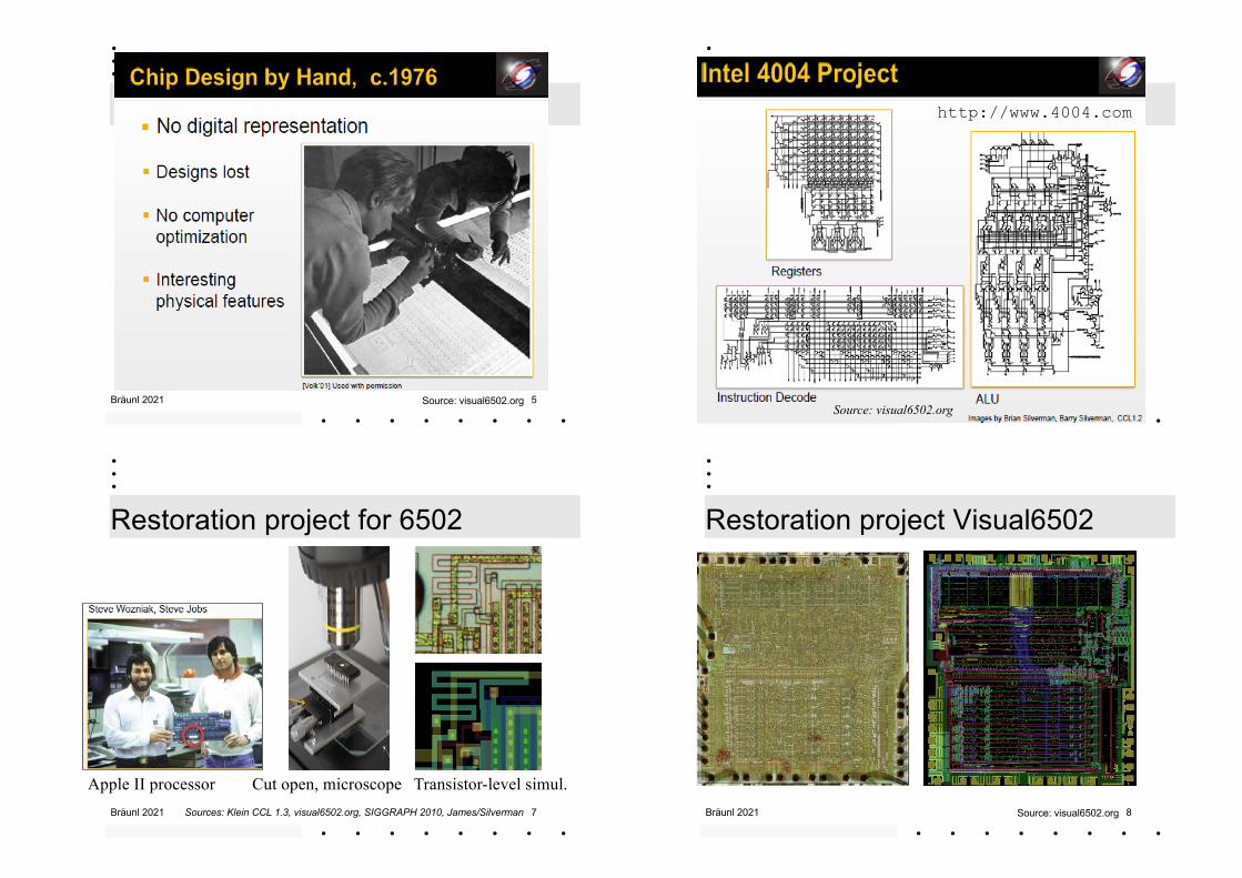
Bräunl 2021 5Source: visual6502.org Bräunl 2021 6
http://www.4004.com
Source: visual6502.org
Bräunl 2021 7
Restoration project for 6502
Sources: Klein CCL 1.3, visual6502.org, SIGGRAPH 2010, James/Silverman
Apple II processor Cut open, microscope Transistor-level simul.Bräunl 2021 8
Restoration project Visual6502
Source: visual6502.org

Bräunl 2021 9http://visual6502.org/JSSim/index.html Bräunl 2021 10
1. Function Units
+
X Y
sum
Higher level of abstraction:• Dealing with words, e.g. 8 bits (lines) at a time• One or two inputs, single output• Outputs can be word or single bit
Add two8bit numbers
Increment8bit number
+ 1
X8
8
= 0
X 8
1Test ifequal to 0
88
8
Bräunl 2021 11
Function Units
+X Y
S
Implement this (4 bit):
Solution:
C-1A A A AC3
S3 S2 S1 S0
X3 Y3 X2 Y2 X1 Y1 X0
Y0
C0C1 0C2
Bräunl 2021 12
Function Units
+1
8
8
Solution: Adder with 2 inputsX
What do I mean by writing “$01” ?
How to build?
+
X$01

Bräunl 2021 13
Function Units
+1
4
4
How to build? Better Solution: Use HAsX
C-1HA HA HA HA
C3
S3 S2 S1 S0
X3 X2 X1 X0
C0C1 1C2
Bräunl 2021 14
Function Units
= 0
8
1
How to build? Solution: NOR gate
Bräunl 2021 15
Function Units
NOT
X4
4
How to build? Solution: NOT gates
Bräunl 2021 16
Function Units
How to build? Solution: 4 AND gates
AND
X Y X Y4 4
4
Bräunl 2021 17
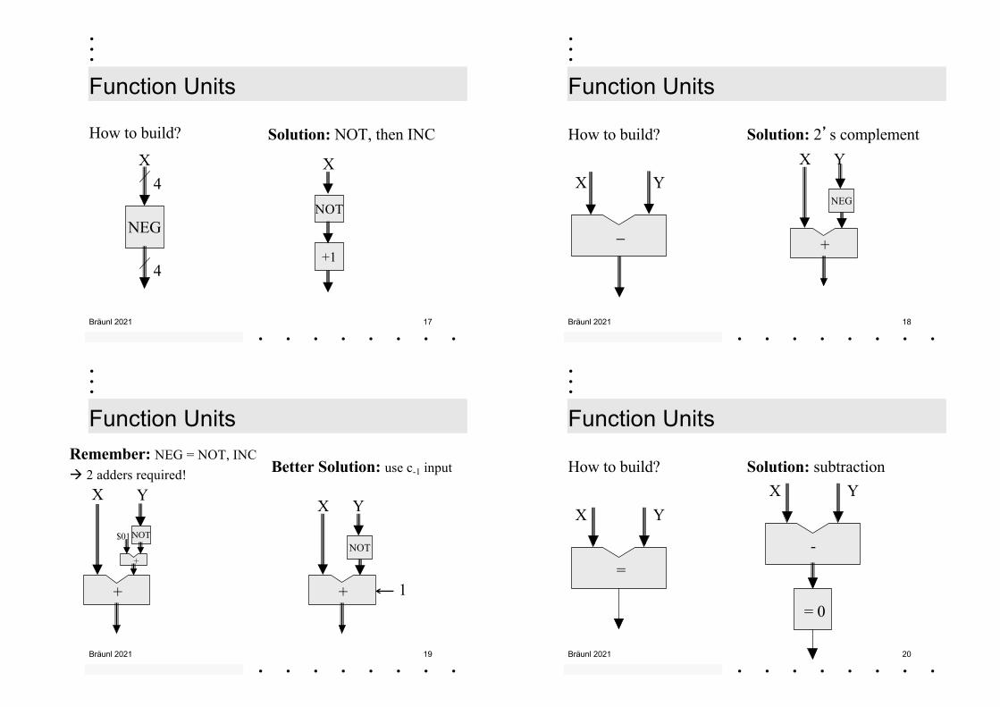
Function Units
NEG
X4
4
How to build? Solution: NOT, then INC
X
NOT
+1
Bräunl 2021 18
Function Units
How to build? Solution: 2�s complement
X Y
+
X Y
NEG
–
Bräunl 2021 19
Function UnitsRemember: NEG = NOT, INCà 2 adders required! Better Solution: use c-1 input
+
X Y
NOT
1+
X Y
NOT
+
$01
Bräunl 2021 20
Function Units
How to build? Solution: subtraction
=
X Y
-
X Y
= 0
Bräunl 2021 21
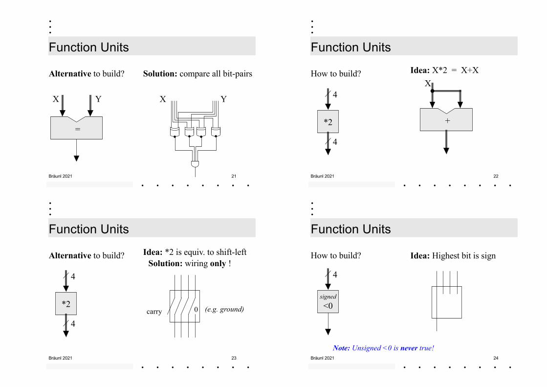
Function Units
Alternative to build? Solution: compare all bit-pairs
=
X Y X Y
Bräunl 2021 22
*2
Function Units
4
4
How to build? Idea: X*2 = X+X
+
X
Bräunl 2021 23
*2
Function Units
4
4
Alternative to build? Idea: *2 is equiv. to shift-leftSolution: wiring only !
0carry (e.g. ground)
Bräunl 2021 24
Function Units
signed<0
4
How to build? Idea: Highest bit is sign
Note: Unsigned <0 is never true!
Bräunl 2021 25
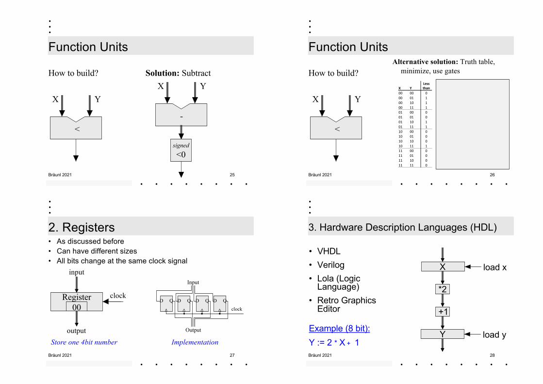
Function Units
How to build? Solution: Subtract
<
X Y
-
X Y
signed<0
Bräunl 2021 26
Function Units
How to build?Alternative solution: Truth table,
minimize, use gates
<
X YX Y
Less than
00 00 000 01 100 10 100 11 101 00 001 01 001 10 101 11 110 00 010 01 010 10 010 11 111 00 011 01 011 10 011 11 0
Bräunl 2021 27
2. Registers• As discussed before• Can have different sizes• All bits change at the same clock signal
Register00
clock
input
outputStore one 4bit number
D Q D Q D Q D Q
clock
Input
Output
Implementation
Bräunl 2021 28
3. Hardware Description Languages (HDL)
load x
load y
X
*2
+1
Y
• VHDL• Verilog• Lola (Logic
Language)• Retro Graphics
Editor
Example (8 bit):Y := 2 * X + 1

Bräunl 2021 29
4. Central Processing Unit (CPU)
Memory
ALU
CPU = ALU + CU• Arithmetic Logic Unit• Control Unit
Also required:• Command table• Signal timing
CU
Data Address
CPU
Bräunl 2021 30
4.1 Arithmetic Logic Unit ALU• Simplest architecture with one data register: Accumulator
• 8 Bit dataData from memory
Function code
Load accumulator
Function Block
Accumulator Register
X
83
Y8
Bräunl 2021 31
Function Block (Example)8 X 8 Y
0 1 2 3 4 5 6 7 Function Code
8
NOT
0 000 Z := X 1 001 Z := NOT X 2 010 Z := X AND Y 3 011 Z := X OR Y 4 100 Z := X + Y 5 101 Z := Y 6 110 Z := X 7 111 Z := X
Z
AND OR +
Bräunl 2021 32
4.2 Control Unit CU• Program counter (PC)• Sequencer
- instruction fetch- PC increment
Address to memory
Load (increment) PC
+1
Program Counter Register
8

Bräunl 2021 33
5.1 Simple CPU 1
ROMData Address
+1
Program Counter Reg. P
8
Function block
Accumulator Register A
3+8= 11
Bräunl 2021 34
Simple CPU 1
+1
Program Counter Reg. PAccumulator
Register A
8
0 1 2 3 4 5 6 7
AND OR +NOT
3+8= 11
ROMData Address
Bräunl 2021 35
Simple CPU 1
Timing in Cycles
Master
A
P
1 2 1 2
Function Codes (Commands)0: Acc := Acc NOP1: Acc := NOT(Acc)2: Acc := Acc AND Data3: Acc := Acc OR Data4: Acc := Acc + Data ADD5: Acc := Data LOAD
Program counter is incremented by1 in each cycle (for each command):PC := PC +1 Bräunl 2021 36
Simple CPU 1
• Example Program to compute 1+2
• Program in memory:
Restrictions• Program never stops
cannot branch/loop• Calculate with constant
values onlycannot load/store datafrom/to memory
address code data comment00 5 01 Load 101 4 02 Add 202 0 00 NOP... 0 00 NOP
Bräunl 2021 37
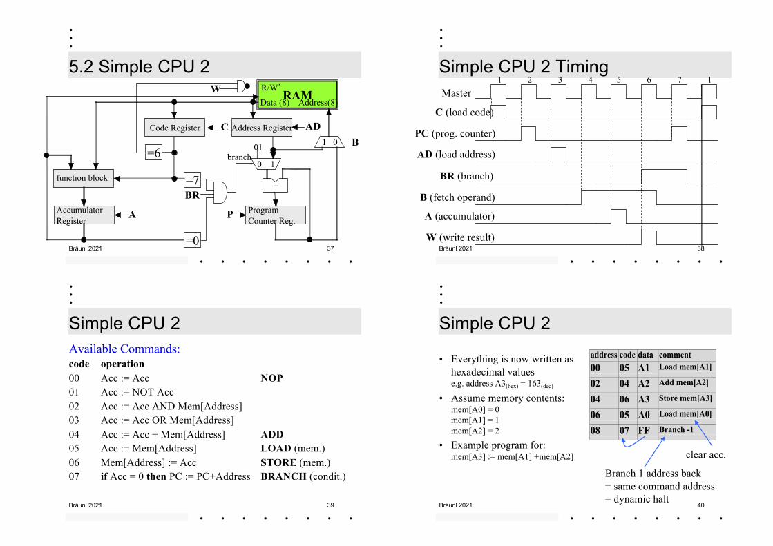
5.2 Simple CPU 2RAM
Data (8) Address(8)
R/W�
=6
W
function block
Accumulator Register
A
CCode Register
Program Counter Reg.
P
+
0 1
1 0 BAddress Register AD
01branch
=0
=7BR
Bräunl 2021 38
Simple CPU 2 Timing1 2 3 4 5 6 7 1
Master
C (load code)
B (fetch operand)
A (accumulator)
W (write result)
PC (prog. counter)
AD (load address)
BR (branch)
Bräunl 2021 39
Simple CPU 2Available Commands:code operation00 Acc := Acc NOP01 Acc := NOT Acc02 Acc := Acc AND Mem[Address]03 Acc := Acc OR Mem[Address]04 Acc := Acc + Mem[Address] ADD05 Acc := Mem[Address] LOAD (mem.)06 Mem[Address] := Acc STORE (mem.)07 if Acc = 0 then PC := PC+Address BRANCH (condit.)
Bräunl 2021 40
Simple CPU 2
• Everything is now written as hexadecimal valuese.g. address A3(hex) = 163(dec)
• Assume memory contents:mem[A0] = 0mem[A1] = 1mem[A2] = 2
• Example program for:mem[A3] := mem[A1] +mem[A2]
address code data comment00 05 A1 Load mem[A1]
02 04 A2 Add mem[A2]
04 06 A3 Store mem[A3]
06 05 A0 Load mem[A0]
08 07 FF Branch -1
clear acc.
Branch 1 address back= same command address= dynamic halt

Bräunl 2021 41
Simple CPU 2
Comments• Each command comprises
2 bytes (command + address)• In each timing cycle (7 steps)
PC is incremented twice:PC := PC + 2(except for branching!)
• Can load and store data from/to memory
Restrictions• Cannot load constant values
• No unconditional branch(must clear Accumulator,then conditional branch)
Bräunl 2021 42
6. Register-Transfer-Object Simulator
http://robotics.ee.uwa.edu.au/retro
Retro
Bräunl 2021 43
http://nandgame.com
Bräunl 2021 44
QUIZ – CPU
Bräunl 2021 45 Bräunl 2021 46
Which one is not a combinatorial circuit ?
A. Adder
B. Flip-flop
C. Multiplexer
D. Comparator
http://robotics.ee.uwa.edu.au/quiz/
Bräunl 2021 47 Bräunl 2021 48
Bräunl 2021 49
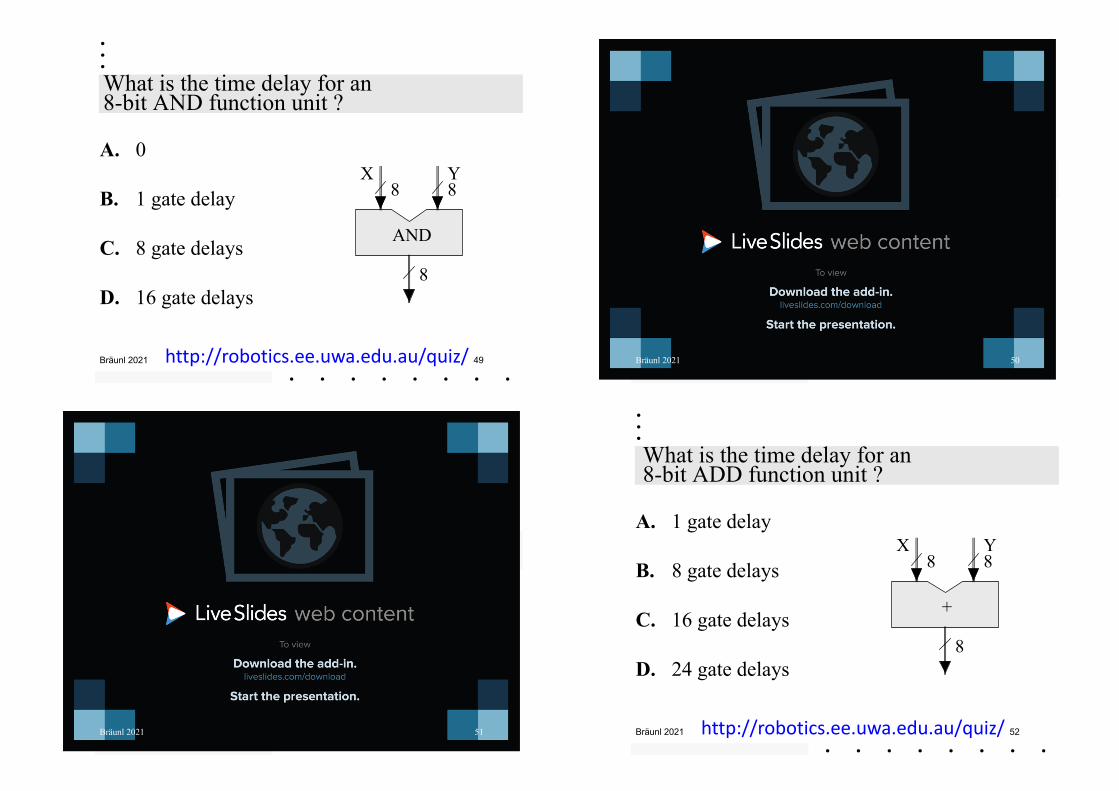
What is the time delay for an8-bit AND function unit ?
AND
X Y8 8
8
A. 0
B. 1 gate delay
C. 8 gate delays
D. 16 gate delays
http://robotics.ee.uwa.edu.au/quiz/ Bräunl 2021 50
Bräunl 2021 51 Bräunl 2021 52
What is the time delay for an8-bit ADD function unit ?
A. 1 gate delay
B. 8 gate delays
C. 16 gate delays
D. 24 gate delays
+
X Y8 8
8
http://robotics.ee.uwa.edu.au/quiz/
Bräunl 2021 53 Bräunl 2021 54