full-scale testing of shear keys for adjacent box … testing of shear keys for adjacent box girder...
TRANSCRIPT

Full-Scale Testing of Shear Keys for Adjacent Box Girder Bridges
80
Richard A. Miller, Ph.D., P.E. Associate Professor of Civil and Environmental Engineering University of Cincinnati Cincinnati, Ohio
George M. Hlavacs Structural Engineer
Middough Associates, Inc. Cleveland, Ohio
Todd Long Project Structural Eng ineer PEDCO E & A Cinc innati , Ohio
Andreas Greuel Graduate Research Assistant
University of Cincinnati Cincinnati , Ohio
Adjacent precast prestressed box girder bridges are widely used in the United States, but the shear keys between the girders tend to crack and leak. Three different shear key configurations were studied, i.e. , a current detail where the shear key is approximately 7 0 in. (250 mm) from the top of the girder and grouted with non-shrink grout, this same detail grouted with epoxy rather than nonshrink grout, and a proposed mid-depth keyway grouted with non-shrink grout. The tests were conducted on a fu ll-scale, four-beam assembly which represented part of a bridge. The results showed that the currently used shear key detail cracks due to thermal stresses generated as the beams deflect upward and downward due to daily heating and cooling. The mid-depth shear key is less susceptible to these stresses and was found to be more resistant to cracking. The epoxied shear keys did not crack. Loading did not appear to cause new cracking, but rather seemed to propagate existing thermal cracks.
A recent survey by the PCI Bridge Committee showed that adjacent precast, prestressed box girder bridges are used in at least 30 states throughout the
United States. These bridges are popular for a variety of reasons. When built as non-composite structures, there is no need to cast and cure a deck, making erection fast and economical even in remote locations. The adjacent box girder bridge also has a favorable span-to-depth ratio, which is important where clearance is a problem.
The use of prestressed adjacent box girder beams started in about 1950 for short span bridges [approximately 30 to
PCI JOURNAL

e E
N
~ .S
I
-~ 1-t-='-="-'='-'
6 in (152 mm)
L /
( --...~ in 13!05 mml '\
~ -"'
100 ft (9 to 28 m)] and they are still most widely used for these spans. The beam design itself evolved from an open channel design. Shear keys in the top flange were used to transfer load between adjacent beams.
When load is applied to a multibeam bridge, adjacent members are forced to deflect simultaneously due to the transfer of vertical shear forces at the joints but the joints between beams are frequently unable to transmit moments in the transverse direction, thus resulting in a hinging action at these joints. When the vertical load is transferred by shear at the joints, it must be carried across the member to the next joint by torsion.
Since open sections are flexible in torsion , a bottom flange is added to the open channel to create a box girder with a higher torsional rigidity . Little else is known about the origin of the box girder, especially how the dimensions of the shear keys, which connect the beams together, were determined. It is likely that these dimensions followed from the open channel design.
While box girder bridges have had a long and successful history , the one problem associated with these bridges was with cracking of the shear key material. The grout used to make the keys has been observed to crack and allow water to leak between the beams. This water is often salt laden and, over time, this water penetrates the beams and causes corrosion of the steel embedded
November-December 1999
~ DETAIL Fig. 1.
DE TAIL
Upper (current detail) and proposed middepth shear keys (Huckelbridge et al.8)
in the beams. 1 While leakage is the major problem, in extreme cases the keys may crack severely enough that the shear key cannot distribute load to adjacent girders, causing an overstress condition in the loaded girder.
Various ideas have been presented to prevent cracking at the shear keys. This paper detai ls three tests which were done to evaluate shear key cracking and possible solutions to the problem.
PREVIOUS RESEARCH Previous research on shear keys
centers on two main items, i.e. , improving the grouting material used in the keys and improving the mechanical behavior of the joint. Gulyas, Wirthlin , and Champa2 performed a laboratory investigation of the grout material. Laboratory tests were conducted on keyway shaped assemblies using standard non-shrink grout and magnesium ammonium phosphate [Mg-NH4- P04] mortars.
Comparative test results show that the Mg-NH4-P04 samples displayed a significantly higher fai lure load than the non-shrink grout composite specimens. The failure mode for the non-shrink grout specimens tended to be at the bond line while the failure mode for the Mg-~-P04 grout was usually at least partially through the substrate. From these tests, Gulyas et al. concluded that shear key performance could be improved with better grout materials.
In a di sc uss ion of the paper by Gulyas et al. ,2 Nottingham3 suggested that problems with the shear key s were the result of poor grout materials, grouting techniques and shear key details . Nottingham also suggested the use of Mg-NH4-P04 grout and presented a full depth shear key detail which is claimed to provide better bond with the grout and be easier to grout properly.
In looking at the mechanical behavior of the shear keys, several recent studies have been published.4•
5•6 These
studies all basically reached the same conclusions: • The shear key connection can be
significantly strengthened and cracking can be reduced or eliminated by providing adequate transverse post-tensioning.
• Improvements in load transfer can be obtained by using some type of full depth shear key. These full depth keys may be continuous or located at discrete points (such as at the position of internal diaphragms in the beams). A study by Stanton and Mattock7
indicated that changing the shape of the shear key would also improve performance.
Ohio Research Box Girder Bridges
Huckelbridge et al., 8•9 conducted a study on Ohio box girder bridges. The upper drawing of Fig. 1 shows the typical beam and shear key detail used. The
81

I nc es 48 I h <122 C M
I 4
l · 4 4 4 ~
Fig. 2. Typical test beam.
33 Inches (84 CM)
4
-~
ch~ MM)
2 In (51 typ I co.l
first part of the study involved truck load testing of bridges with repaired shear keys (i .e., the keys were removed and recast). They found that repaired keys cracked almost immediately after construction . This is consistent with anecdotal evidence from engineers that the shear key grout cracks early; sometimes, even during construction.
In the second phase of the project, Huckelbridge et al. conducted finite element analyses of these bridges and found that when a truck tire rolls over the center of the girder, the top of the box acts like a portal frame, with the fl ange being the beam and the webs acting as columns. Under load , the corners of the box flex inward toward the centerline of the box . Since the shear key is grouted all the way to the top of the box, the flexing of the corners puts a tension on the top of the key, eventually cracking the grout. Cyclic loading propagates the crack until the keyway fails.
To verify the finite element study, Huckelbridge et al. tested full size cross sections, 1 ft (305 mm) thick. Three configurations were tested , namely, a standard configuration filled with non-shrink grout (shown as the upper shear key in Fig. 1), a mid-depth shear key filled with non-shrink grout and the throat of the shear key not grouted (shown as the lower shear key in Fig. 1), and a standard configura-
82
.. ~ 4 i .
.t\4 4 4
• 4
5J 4
I I nches 4 19.5 inches 149. Semi (140 MM)
4
.a 4
~
5 Inches 5 Inches 4 J .1- (130 MM) ( 130 MM) - ' f-
I 4 ."
. . 4 .. .. · . · 4 •4
4
-~ . . T 4., • .. ... . • • . 4S ' '! .. 4·
"' - 10 SP @ 2 Inches ~ (51 I'IM) typl co.l 4 Inches (102
tion filled with epoxy grout. All tests were done under a 10 kip ( 45 kN) cyclic load applied at the center of the top flange.
The standard configuration (top shear key in Fig. 1) fi lled with nonshrink grout failed in the first cycle, with the failure occurring at the bond line between the grout and the beam. The mid-depth shear key fai led at 8 million cycles and the line of fai lure was again at the bond line. The epoxy filled shear key did not fail under the cyclic load.
FIELD TESTING OF FULL SIZE GIRDERS
W ith the promising results of the previous tests, the Ohio Department of Transportation (ODOT) awarded a contract to the University of Cincinnati to conduct full-scale tests of the shear keys.
Four girders were cast, each 75 ft (22.9 m) long, as this is a fairly typical span for an Ohio adjacent box bridge. The cross section and prestressed reinforcement are shown in Fig. 2. Shear reinforcement was provided as #4 stirrups at 2 ft (0.61 m) on center. Concrete had an average compressive strength of 9.4 ksi (64 MPa) at 28 days .
For reasons of economy, the girders were cast with two shear keys, the
• ·-·4 · .. • • A
MM)
'1t I
I I
2 I nches (51 MM)
typl co.l
I 1. 75 I nch <45
es MM)
typl co. l
standard configuration and the middepth key (see Fig. 2). In all, three tests were scheduled . The first test would use the standard configuration with non-shrink grout. After completion of the first test, the beams would be separated and the non-shrink grout would be removed. The second test would use the mid-depth shear key with non-shrink grout. After the second test, the beams would again be separated and the non-shrink grout removed. The final test would consist of testing the standard configuration with epoxy grout.
The four beams were assembled into the center section of an adjacent box girder bridge (see Figs. 3a and 3b ), with the beams set so that the section had a crown, as would be typical of a real bridge. Diaphragms and transverse tie rods were provided as required by ODOT specifications. These tie rods were tightened with a torque wrench prior to casting the shear keys only to pull the beams together; no appreciable transverse post-tensioning was provided.
Loading Apparatus
After assembly, the beams were loaded in a testing frame maintained by the Univers ity of Cincinnati at the Prestress Services plant in Melbourne , Kentucky. Four hydraul ic ac tuators were used to load the
PCI JOURNAL

- ~ · ..... .. .. .. . ~
.. . ' ~
p
1r · ... •.
.. .. · . ELEVATION
Fig. 3a . Schematic of test configuration showing loading of box beams.
p
i": 4
. ~ .... .. ,/ it.
'-~-~--.../ ·: 4. . ... .. :. .•... Legend
e VI bro:tl ng WI re Stro.ln Go.ge <Canto. Ins TherMI star)
Fig. 3b. Four hydraulic actuators were used to load the bridge, two at midspan of each interior beam.
bridge, two at the midspan of each of the interior beams (see Figs . 3a and 3b) . Each actuator applied 10 kips ( 44 .5 kN) , so that each beam was loaded with a total load of 20 kips (89 kN). This total load on each beam is equivalent to one wheel of an HS20-44 truck plus a 25 percent impact.
The actuators were set so that only one interior beam was loaded at a time and the load was completely removed from one beam before the other beam was loaded. In this way, a complete shear reversal was achieved in the center shear key. Each actuator pair was controlled by a single servohy-
November-December 1999
draulic valve. The system could apply one cycle (load each beam once) every 0.9 seconds.
Instrumentation
Figs. 3a, 3b and 4 shows the placement of instrumentation on the bridge. A total of six Direct Current Differential Transducers (DCDT) were placed at one load point, one DCDT on each side of each joint. These instruments measured both the global girder deflection and the differential deflection between girders . Transverse omega clip gauges were placed across the top and bottom of each joint to measure
the tensile strain or crack opening at the joint.
Vibrating wire gauges were placed at the midspan of the girders (see Fig. 3a and 3b ). The two interior girders had vibrating wire gauges in both the top and bottom flange . The two outside girders had vibrating wire gauges installed only in the bottom flange. Vibrating wire gauges were also cast into the center shear key grout at the load points.
Test Method
Prior to tying the beams together with tie rods and casting the first set of
83

EXTERNAL INSTRUMENT ARRANGEMENT
37.5 feet {11 4 m)
I
BEAM #4
<
37.5 feet (11 4 m)
I 4.0 feet
(1 .2J m)
I 4.0 feet
(1 .22 m)
BOTTON AND rr:Rr @~;J/ ~TOP ONLY
BEAM #2 -[ ~: I :J I I
( 4.0 feet 1.22 m)
<
BEAM #1 @"<:.:/ 80~ ONLY
I
I 4.0
1 feet
(1.22 m) I
2.0 feet - + 1- 2.0 feet (0.61 m) (0.61 m)
Fig. 4. External instrument arrangement.
shear keys, each beam was loaded to 20 kips (89 kN) to determine the baseline stiffness and strain characteristics of the individual beam. Load, deflection and strain were measured.
After testing the individual beams, the beams were tied together and the shear keys were cast. For each type of shear key tested, the following routine was used: 1. The shear keys were cast and cured
according to ODOT and/or the grout manufacturer's specifications, asapplicable.
2. The bridge assembly was then subjected to three static loads: (a) 20 kips (89 kN) on one of the
interior beams. (b) 20 kips (89 kN) on the other in
terior beam. (c) 20 kips (89 kN) on both interior
beams, simultaneously. 3. Cyclic loads were applied by plac
ing a load of 20 kips (89 kN) on one of the interior beams, removing the load and then placing a load of 20 kips (89 kN) on the other interior beam. This loading was considered as one cycle and caused a complete shear reversal in the center shear key. Load was applied to 1,000,000 cycles.
4. At intervals of 10; 100; 500; 1000; 5000; 10,000; 50,000; 100,000 and then every 100,000 cycles to 1,000,000, the cyclic testing was stopped. The shear keys were checked
84
for cracks using ultrasonic pulse velocity. Stiffness and load transfer of the bridge was checked by repeating the static tests in previous Item 2.
Crack Detection
Cracks in the keyways were detected using ultrasonic pulse velocity. 10 The pulse-velocity method sends an ultrasonic pulse from a transmitter to a receiver located some distance away. If there are no cracks, the pulse goes directly from the transmitter to the receiver. Since the wave cannot go through a crack, the presence of a crack causes the wave to go around the crack, increasing the travel time from transmitter to receiver. Completely cracked concrete transmits no waves.
The shear keys were checked for cracks at intervals of 3 ft (0.91 m) along the length of the joint. The transmitter and receiver were placed on opposite sides of the joint, 3 in. (75 mm) apart. Tests on sound concrete showed the wave transmission time to be about 30 to 50 JlS. Thus, keyways with transmission times of 50 JlS were considered uncracked, although some had minor surface cracks.
Cracks with transmiss ion times of 50 to 500 JlS were arbitrarily considered to have moderate cracks while cracks with transmission times over 500 JlS were considered to have severe cracking (this included completely
LEGEND @) "TRANSVERSE a.JP GAGE
@ LVDCOT
G POINT LOAD
cracked shear keys, which had infinite transmission times). For the first shear key test, the pulse velocity method was verified using dye penetration. 10
The pulse velocity method finds discontinuities in the concrete or grout and the results of the pulse velocity tests could have been affected by voids due to improper consolidation. However, at the end of each load test, the beams were separated and the shear key grout was removed. During this process, the grout was carefully inspected for the presence of voids and none were found.
TESTS ON CURRENT OHIO SHEAR KEY
The first test used the current Ohio shear key design (see upper shear key in Figs. 1 and 2). Because the shear keys were grouted in late November, the assembly was covered with a plastic tent and heated for seven day s. Thermistors in the vibrating wire strain gauges, installed in both the beams and the shear keys, were used to monitor temperature and the data showed the grout did not freeze during the seven-day heating period, during which the grout reached the specified full strength of 5000 psi (35 MPa).
After the grout reached full strength, the shear keys were inspected and only minor surface cracks (probably shrinkage) were found. As the test was
PCI JOURNAL

CRACKING AT 0 CYCLES 75 feet
I ~ -j I
2'
~!- • - 13.5' 2'
7.5' I-.· 7.5'
I T ru . N
CRACK PROPAGATION AT 10 ,000 CYCLES
11--------- 75 f eet ---------1
[1~13.5::-. - - 1-7.7-:-, #·ru...._~ ... ;---= .... ~ .. :-31
-· s·--!J.-5
• -I
CRACK PROPAGATION AT 41 ,000 CYCLES
I 75 feet I
ru I~ I
1-l ~2'
---L-..r!- !- 2' 43.7'
10.5' 20.7' l=-r · . 13.5'
I T
- SEVERE CRACKING - CRACKED COMPLETELY THROUGH AS INDICATED BY PULSE VELOCITY
MODERATE CRACKING - PARTIAU. Y CRACKED AS INDICATED BY PULSE VELOCITY
NO CRACK OR SUPERFICIAL CRACKING
LOAD POINT
Fig. 5. Crack propagation in Test 1 a with upper shear key, non-shrink grout.
about to begin, some cold, snowy weather arrived and the testing was delayed until early January. When the shear keys were inspected prior to the start of the test, they were found to be cracked (see Fig. 5).
Data collected from the vibrating wire gauges cast in the keys , which had been monitored continuously since the keys were cast, revealed the cause. The recorded strain in one of the gauges abruptly jumped at the same time the thermistor in the gauge recorded the first hard freeze (,O' F or -18 ' C). It was clear that temperature had cracked the keys. Since the keys were cracked, it was decided to abandon this test, remove and recast the keys for a new test. However, before the test was abandoned, the bridge was tested to a limited number of cycles
November-December 1999
(about 40,000) to check the loading and instrumentation systems.
Fig. 5 shows the results of this limited test. It is clear that the initial cracks, caused by temperature, propagated during loading and that loading did not cause new cracks. However, it is important to remember that the beams were tested outside so there is no way to know if the crack propagation was caused by loading or by additional temperature effects.
After the limited test, the beams were cut apart and the shear key grout removed with chipping hammers. The bridge was then reassembled and the shear keys regrouted. To avoid weather problems, the grouting was done in May. The grout was allowed to gain strength for one week to ensure that it would surpass the required 5000
psi (35 MPa) strength. During the curing period, the bridge was fully instrumented and monitored.
After one week, the bridge was inspected and the shear keys were again found to be cracked. Evaluation of the data showed the cause. During the day, the top of the beams are heated by the sun while the bottom of the beams remain near ambient temperature (see Fig. 6a). The daily temperature increases cause a lengthening of the beam while the temperature gradient causes the beams to deflect upward (camber). The camber varied from day to day , but the maximum was measured at 0.5 in. (13 mm).
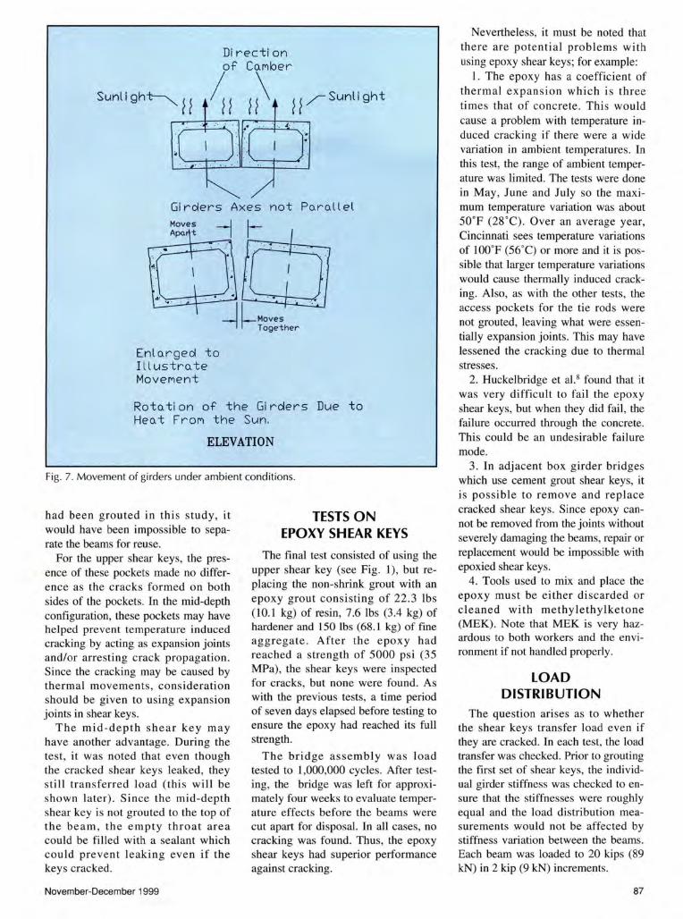
It was also found that the shear key joints open or close as the beams move due to temperature (see Fig. 6b). It appears that the beams are never perfectly aligned on the abutments and, as a result, the axes of adjacent beams are at an angle (see Fig. 7). During the day, the sun heats the top of the beam and the uneven heating causes an upward deflection. At night, the beams cool and there is a downward deflection. These temperature induced movements cause the beams to move along their axes and this causes opening and closing of the joints (see Fig. 7).
Note that the opening or closing of joints is based on how the beams rest on the abutment. Some joints open when the beams deflect upward and close when the beams deflect downward. Other joints close when the beams deflect upward and open when the beams deflect downward.
It is also probable that the shear keys act as hinges and the beams rotate about the keys. In the usual shear key detail, the area below the key is not grouted and, if the beams do not touch , the beams are free to rotate below the key. However, the area above the key is restrained by grout and this restraint generates stresses which eventually crack the grout. It is possible that filling the area under the shear key with grout (using a full depth shear key) may limit the hinging at the shear key. This may be why the full depth shear keys used in New York and Alaska have been reported to be successful.' ..
Omega gauges placed across the joints showed maximum transverse
85

-(J -
D 6 12 18
TIME (HOURS)
__.._ TOP STRAIN -- BOTTOM STRAIN - TEMP DIFFERENCE
Fig. 6a. Example of top and bottom strains in girder with thermal gradient (difference between top and bottom temperature).
400
300 z < 200 0::: 1-en 0 0::: 100 (.)
~ 0
-100 0 6 12 18 24
TIME (HOURS)
Fig. 6b. Example of transverse strains at top of shear key, due to therma l stresses, for a typical 24-hour cycle.
tensile strains of more than 300 J.iE (see Fig. 6b). This is enough to crack the shear keys. Thus, it appears that the shear keys crack almost immediately due to temperature effects. This explains why Huckelbridge et al. 8
found cracking soon after construction of the shear keys.
The shear keys were tested to 1,000,000 cycles of load and checked for cracks (Fig. 8). As before, the loading mostly propagated existing cracks, although some new cracking occurred during the loading phase.
86
Again, it cannot be ascertained as to whether these cracks were caused by the loads or by additional temperature movement.
TESTS ON MID-DEPTH SHEAR KEY
Huckelbridge et a!. 8 believed that cracking in the shear keys was caused by portal frame action in the top of the box. As a result, they suggested that the cracking could be stopped by moving the shear key down to the neutral
axis of the girder and grouting only the key, leaving the throat empty.
As previously noted, each beam was cast with two shear keys, an upper, or standard, shear key, corresponding to the current detail , and a lower, middepth shear key (see Fig. 2). After the test of the upper shear key, the beams were cut apart and the old grout was removed. The beams were reassembled and the lower, mid-depth, shear key was grouted with non -shrink grout.
The contractor used normal procedures for grouting these shear keys , except that he only grouted the keys , not the throat. This was done by using a piece of board, properly marked to the top of mid-depth shear key , to screed the grout. The grout was allowed to cure until it reached the required strength of 5000 psi (35 MPa).
Prior to testing, the shear keys were inspected for cracks using pulse velocity. Some cracking was found near the ends of the girders. However, while the cracks completely penetrated the shear keys, they did not extend far along the shear keys. The extension lengths were about 12 in. (300 mm). The beams were loaded to 1,000,000 cycles using the method previously described. Only one crack at the end of the beam propagated (see Fig. 9). The total length of the crack was approximately 3 ft (0.92 m).
The performance of these mid-depth shear keys may have been aided by the way in which the key s were constructed. Tie rods were used to hold the beam together and the spacing of the rods is set by ODOT specification. For these beams, a total of five tie rods were used, i.e., one at midspan, one located at 26ft (7.9 m) from each end of the beam and one located 27 in . (686 mrn) from each end.
When the beams are cast, pockets are left in the top of the beam at the tie rod positions to allow the workers access to the ends of the tie rods for positioning and tightening of the tie rods. These pockets are 33/s in . (86 mm) wide (perpendicular to the joint), 15 in. (380 mrn) long and the depth is to the bottom of the shear key. Normally, these pockets are grouted and the shear key is made continuous through these areas. However, if the pockets
PCI JOURNAL
~~/Sunlight
Gi rclers Axes not Po.ro.ll el
Enl o.rgecl to I l l ustro. te MoveMent
Roto.tion of the Girders Due to Heo. t FroM the Sun.
ELEVATION
Fig. 7. Movement of girders under ambient conditions.
had been grouted in this study, it would have been impossible to separate the beams for reuse.
For the upper shear keys, the presence of these pockets made no difference as the cracks formed on both sides of the pockets. In the mid-depth configuration, these pockets may have helped prevent temperature induced cracking by acting as expansion joints and/or arresting crack propagation . Since the cracking may be caused by thermal movements, consideration should be given to using expansion joints in shear keys.
The mid-depth shear key may have another advantage. During the test, it was noted that even though the cracked shear keys leaked, they sti ll tran sferred load (this will be shown later). Since the mid-depth shear key is not grouted to the top of the beam , the empty throat area could be filled with a sealant which could prevent leaking even if the keys cracked.
November-December 1999
TESTS ON EPOXY SHEAR KEYS
The final test consisted of using the upper shear key (see Fig. 1), but replacing the non-shrink grout with an epoxy grout consisting of 22.3 lbs (10.1 kg) of resin, 7.6 lbs (3.4 kg) of hardener and 150 lbs (68.1 kg) of fme aggregate. After the epoxy had reached a strength of 5000 psi (35 MPa), the shear keys were inspected for cracks, but none were found. As with the previous tests, a time period of seven days elapsed before testing to ensure the epoxy had reached its full strength .
The bridge assembly was load tested to 1,000,000 cycles. After testing, the bridge was left for approximately four weeks to evaluate temperature effects before the beams were cut apart for disposal. In all cases, no cracking was found. Thus, the epoxy shear keys had superior performance against cracking.
Nevertheless, it must be noted that there are potential problems with using epoxy shear keys; for example:
I. The epoxy has a coefficient of thermal expansion which is three times that of concrete. Thi s would cause a problem with temperature induced cracking if there were a wide variation in ambient temperatures. In this test, the range of ambient temperature was limited. The tests were done in May, June and July so the maximum temperature variation was about 50oF (28 oC) . Over an average year, Cincinnati sees temperature variations of lOOOF (56°C) or more and it is possible that larger temperature variations would cause thermally induced cracking. Also, as with the other tests, the access pockets for the tie rods were not grouted, leaving what were essentially expansion joints. This may have lessened the cracking due to thermal stresses.
2. Huckelbridge et al.8 found that it was very difficult to fail the epoxy shear keys, but when they did fail, the fai lure occurred through the concrete. This could be an undesirable failure mode.
3. In adjacent box girder bridges which use cement grout shear keys, it is possible to remove and replace cracked shear keys. Since epoxy cannot be removed from the joints without severely damaging the beams, repair or replacement would be impossible with epoxied shear keys.
4. Tools used to mix and place the epoxy must be either discarded or cleaned with methylethylketone (MEK). Note that MEK is very hazardous to both workers and the environment if not handled properly.
LOAD DISTRIBUTION
The question arises as to whether the shear keys transfer load even if they are cracked. In each test, the load transfer was checked. Prior to grouting the first set of shear keys, the individual girder stiffness was checked to ensure that the stiffnesses were roughly equal and the load distribution measurements would not be affected by stiffness variation between the beams. Each beam was loaded to 20 kips (89 kN) in 2 kip (9 kN) increments.
87

The deflection was measured and a best fit line constructed for the P-!:1 curve. Knowing the length of the beam and the position of the load, El could be calculated. The average El was measured to be 6.00 x 10⁸ kip-in .2
(1.72 x 10¹² kN-mm2) with no single measurement varying from the average by more than 10 percent. Given the uncertainties of I and especially E, a 10 percent variation of stiffness is acceptable.
After grouting the shear keys, the load distribution for the bridge was found by placing a load of 20 kips (89 kN) on one of the interior beams (Beam 2 or 3 in Fig. 4) and measuring the ten sile strains in the bottom flanges of all beams. The percentage load taken by a single beam is found from the strain measured in that beam divided by the sum of the strains in all four beams. Measurements for load di stribution were taken prior to the first load cycle and then at various intervals of the load cycles (see Test Method). For a given test, it was found that the percentage of load taken by each girder was essentially constant for any number of load cycles and did not vary by more than 1 percent of the total over the entire 1,000,000 load cycles. The final load distributions are presented in Tables 1 to 4.
Table 1 shows the load distribution for the epoxy shear keys. Since these keys never cracked, this represents ideal load transfer. The loaded beam and its adjacent edge beam carry a slightly larger percentage of the load in each case while the other two beams carry slightly less load. This may be due to the crown in the bridge.
From Tables l to 4, it appears that the load distribution is fairly uniform. The worst case is for the upper shear key with non-shrink grout (see Table 2) where the loaded beam and its adjacent edge beam take 29 percent of the load while the other two beams take 21 percent. However, this compares favorably (within the stated accuracy) with the ideal case in Table 1 where the loaded beam and its adjacent edge beam each take about 27 percent of the load and the other two beams take approximately 23 percent of the load.
It is also interesting to note that if a designer assumed all the beams shared
88
CRACKING AT 0 CYCLES 1-1-------- 75 feet ---------1
:II~.~~::a·--~2"~ii~_+te--\· __ ~p~· N N
CRACK PROPAGATION AT 100)000 CYCLES
.T .... . .. ~
.... j_
I 75 fee t I
I
I -r-- 2' 3.20..
13. :5' ---1-rT' ;-u.61" 16.46 .. 2.29..
37. :5' 1-.· . I I
' I N
ru CRACK PROPAGATION AT 500)000 CYCL ES
75 f " " 1
I
16.5' I -r-- 2' 10.5'
19. :5' ---1-rT' !-<!~2' 13.:5'
49.5' 1-.· . I I
' ' N N
CRACK PROPAGATION AT 900)000 CYCLES
I 75 feet I
I
16.5' -j ~2' 16.5'
22. 6' ----'--1"' • !-CU. 16.:5'
49. 5' 1---r· . IJ ' ' N N
- SEVERE CRACK ING - CRACKED CJ:M'LETELY THROUGH AS INDICATED BY PULSE VELOCITY
lllDERATE CRACKING - PARTIALLY CRACKED AS INDICATED BY PULSE VELOC ITY
t«< CRACK DR SUPERF'ICIAL CRACKING
LOAD POINT
Fig. 8. Crack propagation Test 1 b with upper shear key, non-shrink grout.
q;; Fig. 9.
~. =I=
Crack propagation
,.j in Test 2 with mid-depth shear key, non-shrink grout.
0 CYCLES q;
L =I= ,j
1,000,000 CYCLES
SEVERE CRACKING
~ MODERATE CRACKING
NO CRACKING N
• LOAD POINT ~
PCI JOURNAL
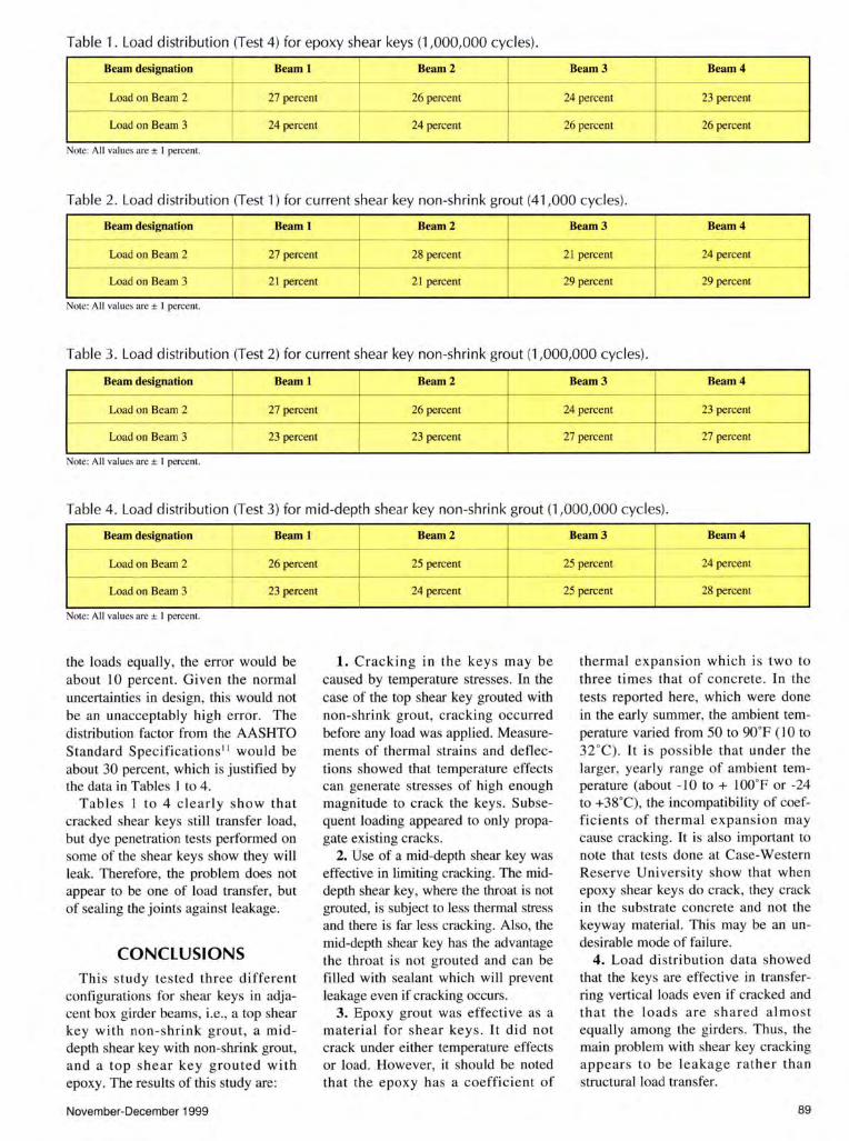
Table 1. Load distribution (Test 4) for epoxy shear keys (1,000,000 cycles).
Beam designation I Beam l Beam2 Beam3 Beam4 r-- -- - 1------ --- - f---- ---
Load on Beam 2
I 27 percent 26 percent 24 percent 23 percent
~ --- -- - +-- -- --- -- ~ I-- ---
Load on Beam 3 24 percent 24 percent 26 percent 26 percent
Note: All values are ± I percent.
Table 2 . Load distribution (Test 1) for current shear key non-shrink grout (41,000 cycles) .
Beam designation Beam l Beam2 Beam3 Beam4 1-- --- - - f-- - ·
Load on Beam 2 27 percent 28 percent 21 percent 24 percent ~ -- -- ---
Load on Beam 3 I 2 1 percent 21 percent 29 percent 29 percent
Note: All values are ± I percent.
Table 3 . Load distribution (Test 2) fo r curre nt shear key non-shrink grout (1,000,000 cycles) .
Beam designation Beam l Beam2 Beam3 Beam4 f-- --·· ----
Load on Beam 2 27 percent 26 percent 24 percent 23 percenl -- --- - -
Load on Beam 3 23 percent 23 percent 27 percent 27 percent
Note: All values are ± I percent.
Table 4. Load distribution (Test 3) for mid-depth shear key non-shrink grout (1,000,000 cycles).
Beam designation Beam l -- ---
Load on Beam 2 26 percent r- --
Load on Beam 3 23 percent
Note: All values are ± I percent.
the loads equally , the error would be about 10 percent. Given the normal uncertainties in design, this would not be an unacceptably high error. The distribution factor from the AASHTO Standard Specifications 11 would be about 30 percent, which is justified by the data in Tables I to 4.
Tables I to 4 clearly show that cracked shear keys still transfer load, but dye penetration tests performed on some of the shear keys show they will leak. Therefore, the problem does not appear to be one of load transfer, but of sealing the joints against leakage.
CONCLUSIONS This study tested three different
configurations for shear keys in adjacent box girder beams, i.e., a top shear key with non-shrink grout, a middepth shear key with non-shrink grout, and a top shear key grouted with epoxy. The results of this study are:
November-December 1999
Beam2 ---
25 percent
24 percent
1. Cracking in the keys may be caused by temperature stresses. In the case of the top shear key grouted with non-shrink grout, cracking occurred before any load was applied. Measurements of thermal strains and deflections showed that temperature effects can generate stresses of high enough magnitude to crack the keys. Subsequent loading appeared to only propagate existing cracks.
2. Use of a mid-depth shear key was effective in Limiting cracking. The middepth shear key, where the throat is not grouted, is subject to Jess thermal stress and there is far less cracking. Also, the mid-depth shear key has the advantage the throat is not grouted and can be fi lled with sealant which will prevent leakage even if cracking occurs.
3. Epoxy grout was effective as a material for shear keys. It did not crack under either temperature effects or load. However, it should be noted that the epoxy has a coefficient of
Beam3 Beam4 - - -- --
25 percent 24 percent
25 percent 28 percent
thermal expansion which is two to three times that of concrete. In the tests reported here, which were done in the early summer, the ambient temperature varied from 50 to 90"F ( 10 to 32"C). It is possible that under the larger, yearly range of ambient temperature (about -10 to+ lOO"F or -24 to +38"C), the incompatibility of coefficients of thermal expansion may cause cracking. It is also important to note that tests done at Case-Western Reserve University show that when epoxy shear keys do crack, they crack in the substrate concrete and not the keyway material. This may be an undesirable mode of failure.
4. Load distribution data showed that the keys are effective in transferring vertical loads even if cracked and that the loads are shared almost equally among the girders. Thus, the main problem with shear key cracking appears to be leakage rather than structural load transfer.
89
RECOMMENDATIONS Cracking of the shear key grout ap
pears to occur due to thermal and/or load induced movements of the bridge beams. These beam movements cause opening (or closing) of the joints between the girders. While it may not be possible to completely prevent cracking in the shear keys, cracking can be reduced by:
1. Use a grout material with high bond strength . Epoxy worked very well in this study, although there are some concerns about thermal compatibility . Magnesium ammonium phosphate [Mg-NH4-P04] mortars have also been found to work well.
2. Reduce the stress on the shear key grout by moving the key to the neutral axis and not grouting the throat (the area above the shear key). This may be effective because the shear key was able to act like a hinge.
3. Prevent opening of the joint. Transverse prestressing would stop this opening. Also, it is possible that a full depth shear key may stop the joint from acting like a hinge and prevent the joint from opening. This is because in the current designs, the area below the key is open and free to move. If this area were grouted, the movement of the joint may be reduced.
4. Since it may not be possible to prevent cracking, seal and/or drain the shear keys to prevent leakage.
SUGGESTIONS FOR FUTURE RESEARCH
1. The mid-depth shear key was less susceptible to cracking, perhaps because, without the throat grouted, it acted like a hinge. The current shear key design should be retested, but this time without the throat grouted to see if the same hinging occurs and if there is less cracking.
2. Test the full depth shear keys to see if opening stresses on the joint are reduced.
3. Retest the epoxy shear keys, but include a wide range of temperature variations to assess thermal compatibility.
4. More testing is needed to determine the minimum amount of transverse prestressing which would be needed to prevent cracking.
5. Finally, it may not be possible to eliminate all cracking; therefore, a detail should be developed to seal and/or drain the shear keys to keep salt laden water from penetrating the girders and attacking the reinforcing steel.
REFERENCES
ACKNOWLEDGMENTS This research was funded by the
Ohio Department of Transportation and the Federal Highway Administration. Thanks are due to the following ODOT personnel: Vik Dalal, Roger Green, Brad Fagrell , Lloyd Welker, William Edwards (retired), and Dave Hanhilammi (retired) . The authors also thank Dr. Huckelbridge and Dr. El-Esnawi of Case Western-Reserve University for their help and excellent initial research program. The help of Master Builders, which provided technical and field support for the epoxy grouting operation, is appreciated. Finally, the authors thank Don Bosse, Joe Roche and the excellent staff of Prestress Services, Melbourne, Kentucky for their help and support in the testing phases.
DISCLAIMER This paper reflects the views of the
authors, who are solely responsible for the accuracy and interpretation of the data presented. It does not necessarily reflect the official views or policies of ODOT or FHW A and does not constitute a standard, specification, regulation or endorsement of a product or method.
l. Miller R. A., and Parekh, K. , "Destructive Testing of a Deteriorated Prestressed Box Bridge Beam," Transportation Research Record, No. 1460, 1994, pp. 37-44.
7. Stanton, J. F., and Mattock, A. H. , "Load Distribution and Connection Design for Precast, Stemmed Multibeam Bridge Superstructures," NCHRP Report 287, Transportation Research Board, Washington, DC, 1986. 2. Gulyas, R. J., Wirthlin, G. J., and Champa, J. T ., "Evaluation
of Keyw ay Grout Test M ethods for Precast Concrete Bridges," PCI JOURNAL, V. 40, No . 1, January-February 1995, pp. 44-57.
3. Nottingham, D., Discussion of "Evaluation of Keyway Grout Test Methods for Precast Concrete Bridges," by Gulyas, Wirthlin and Champa, PCI JOURNAL, V. 40, No. 4, July-August 1995, pp. 98-103.
4. Lall, J., Alampalli, S., and DiCocco, E. F., "Performance of Full Depth Shear Keys in Adjacent Prestressed Box Beam Bridges," PCI JOURNAL, V. 43, No. 2, March-April 1998, pp. 72-79.
5. E!-Remaily, A., Tadros, M. K., Yamane, T., and Krause, G., "Transverse Design of Adjacent Prestressed Concrete Box Girder Bridges," PCI JOURNAL, V. 41 , No. 4, July-August 1996, pp. 96-107.
6. Yamane, T., Tadros, M. K. , and Arumugasaamy, P., "Short to Medium Span Precast Prestressed Concrete Bridges in Japan," PCI JOURNAL, V. 39, No. 2, March-April 1994, pp. 74-100.
90
8. Huckelbridge, A. A., El-Esnawi, H. H., and Moses, F., "Shear Key Performance in Multibeam Box Girder Bridges," Journal of Performance of Constructed Facilities, V. 9, No. 4, November 1995, pp. 271-285.
9. El-Esnawi, H. H., "Evaluation of Improved Shear Key Design for Multi-Beam Prestressed Concrete Box Girder Bridges," A Thesis submitted to the Faculty of the Department of Civil Engineering in partial fulfillment of the requirements for the degree of Doctor of Philosophy, Department of Civil Engineering, Case-Western Reserve Univers ity, Cleveland, OH, January 1996.
10. Hlavacs, G. M., Long, T., Miller, R. A., and Baseheart, T. M. , "Nondestructive Determination of Response of Shear Keys to Environmental and Structural Cyclic Loading," Transportation Research Record, No. 1574, 1997, pp. 18-24.
11 . Standard Specifications for Highway Bridges, 16th Edition , American Association of State Highway and Transportation Officials, Washington, DC, 1995.
PCI JOURNAL