full adder vhdl ppt
DESCRIPTION
A power point presentation on full adder with some more programs to bring a hand-on experience to beginners on VHDL modelling using Xilinx.TRANSCRIPT

1
VHDLStructural Modeling
EL 310Erkay Savaş
Sabancı University

2
Structural Modeling• Behavioral Modeling (describing internal
behavior of a component)– CSA statements (dataflow model)– Process
• Structural Modeling– Describes how the components are connected.– Behavioral models are assumed to exist in local
working directory or in a library.– Structural modeling facilitate the use of hierarchy
and abstraction in modeling complex systems– Structural models can be integrated into models
that also use processes and CSA statements

3
Describing Structure• Block diagrams
– Components are represented by blocks interconnected by lines representing signals.
• Full Adder
HA1 HA2in1
in2
c_in
sum
c_out
s1
s2
s3 O1

4
Full Adder • We assume that we have the description of
half adders and or gate.– Actually, we are not interested in the internal
behavior of these components.• To connect them, what we need is the
interface of each component.
x
y
sum
carry
x
yz
Each component, signal and ports of componentshave names

5
Connecting Components• List of components• Uniquely labeling components to distinguish
among multiple instances of the same component.
• Set of signals connecting them• Specify how signals are connected to ports of
components.

6
library IEEE;use IEEE.std_logic_1164.all;
entity full_adder isport(in1, in2, c_in: in std_logic;
sum, c_out: out std_logic);end entity full_adder;
architecture structural of full_adder is
component half_adder isport (x,y: in std_logic;
sum, carry: out std_logic);end component half_adder;
component or_2 isport (x,y: in std_logic;
z: out std_logic);end component or_2;
signal s1, s2, s3: std_logic;beginH1: half_adder port map(x=>in1, y=>in2, sum=>s1, carry=>s3);
H2: half_adder port map(x=>s1, y=>c_in, sum=>sum, carry=>s2);
O1: or_2 port map(x=>s2, y=>s3, z=>c_out);
end architecture structural;
Structural Model of a Full Adder
component declarations
signal declarations
component instantiationstatements

7
Structural Model• Different instances of a component have
identical input port names.– This is not a problem; since the port name is
associated with a specific instance through a unique label.
• Components that are going to be used are declared within the declarative region of the architecture– The actual description must be placed somewhere
that CAD tools can locate: e.g. working directory, a library, or in some directory whose path is in the search path of CAD tools.
8
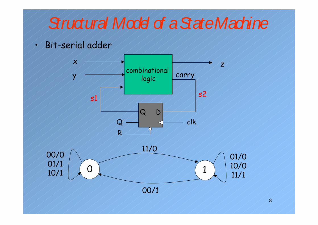
Structural Model of a State Machine• Bit-serial adder
combinational logic
Q Dclk
RQ’
0 1
11/0
00/1
x
yz
carry
01/010/011/1
00/001/110/1
s2s1

9
Bit Serial Adderlibrary IEEE;use IEEE.std_logic_1164.all;
entity serial_adder isport(x, y, clk, reset: in std_logic;
z: out std_logic);end entity serial_adder;
architecture structural of serial_adder is
component comb isport (x,y, c_in: in std_logic;
z, carry: out std_logic);end component comb;
component dff isport (D,clk, R: in std_logic;
Q, Qbar: out std_logic);end component dff;
signal s1, s2: std_logic;beginC1: comb port map(x=>x, y=>y, c_in=>s1, z=>z, carry=>s2);
D1: dff port map(D=>s2, clk=>clk, R=>reset, Q=>s1, Qbar=>open);
end architecture structural;
port on the component signal or port
on the entity
We cannot assume that port names are unique.not connected

10
Constructing Structural VHDL Models• Two Steps:
– Drawing the annotated schematics– Converting it to VHDL
• Make sure that description of components you will use is available. – i.e. a working entity-architecture pair.– Using entity descriptions, create a block for each component.
• connect each port of every component to the port of another entity or to the input or output port of the entity being modeled.
• Label each component• Label each internal signal• Label each system input and output port, define its
mode and type

11
Structural Model Templatelibrary library-name-1, library-name-2;use library-name-1.package-name.all;use library-name-2.package-name.all;
entity entity_name isport(input signals: in type;
output signals: out type);end entity entity_name;
architecture structural of entity_name is-- declare components used
component component1-name isport (input signals: in type;
output signals: out type);end component component1-name ;
component component2-name isport (input signals: in type;
output signals: out type);end component component2-name ;
-- declare al signals used to connect the components.
signal internal signals: type:=initialization;begin-- label each component and connect its ports to signals or entity portsLabel1: component1-name port map(port=>signal, ...);Label2: component2-name port map(port=>signal, ...);
end architecture structural;

12
Adder Design with Structural VHDL
ALU0a0
b0
c0
ALU1a1
b1
ALU2a2
b2
s0
c1
1st Clock Cycle
s1
c2
2nd Clock Cycle
s2
c3
3rd Clock Cycle
ALU3a3
b3s3
c4
4th Clock Cycle
• (1111) + (0001) worse case addition
• Carry-ripple adder

13
A Faster Adder• To add two corresponding bits of A an B, we
have to know the carry from the sum of previous bits.
• c1 = b0c0 + a0c0 + a0b0• c2 = b1c1 + a1c1 + a1b1 =(b1+a1)(b0c0+a0c0+a0b0)+a1b1
• c3 = b2c2 + a2c2 + a2b2 =(b2+a2)(b1+a1)(b0c0+a0c0+a0b0)+a1b1+a2b2
• c4 = b3c3 + a3c3 + a3b3 =(b3+a3)(b2+a2)(b1+a1)(b0c0+a0c0+a0b0) + a1b1+ a2b2 + a3b3 =
• Can you imagine the length of the expression for c32?

14
Carry Lookahead - 1• An approach in-between the two extremes• Motivation:
– If we didn't know the value of carry-in, what could we do?
– When would a carry be always generated? gi = aibi
– When would the carry be propagated? pi = ai+bi
• Using them we can write the following formulaci+1 = gi+pici
• To see where the signals get their names suppose gi=1 � ci+1=1+pici= 1
that is, the adder generates the CarryOut (independent of CarryIn)

15
Carry Lookahead – 2• gi = 0 and pi = 1 � ci+1=ci
• That is CarryIn is propagated to CarryOut.c1 = g0 + p0c0c2 = g1 + p1c1 = g1 + p1g0 + p1p0c0c3 = g2 + p2c2 = g2 + p2g1 + p2p1g0 +p2p1p0c0c4 = g3 + p3c3 = g3 + p3g2 + p3p2g1 +p3p2p1g0 + p3p2p1p0c0
• Question: How can we compute pis and gisefficiently?

16
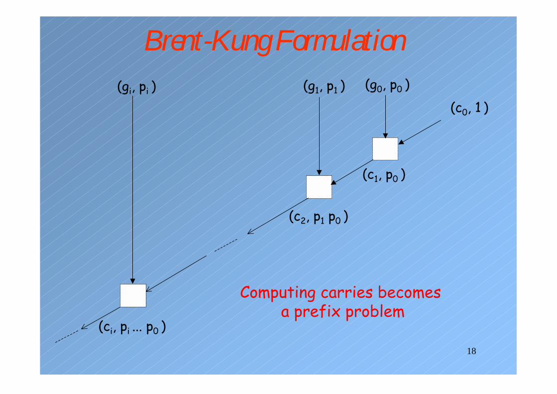
Brent-Kung Formulation• An associative operation:
– (x, y)• (w,z) = (x+yw, yz)• Apply this operation to the pis and gis• (c0, 1)
• (g0, p0)•(c0, 1)=(g0+ p0c0, p0)= (c1, p0)
• (g1, p1)•(c1, p0)=(g1+ p1c1, p1p0)=(c2, p1p0)
• (g2, p2)•(c2, p1)=(g2+ p2c2, p2p1p0)=(c2, p2p1p0)
• ...
• (gi, pi)•(ci, pi…p1p0)=(gi+ pici, pi…p1p0)=(ci+1, pi…p1p0)

17
Brent-Kung Circuit
gi
pi
ci
pi-1 ...p1 p0
ci+1
pi pi-1 ...p1 p0
(gi, pi)•(ci, pi…p1p0)=(gi+ pici, pi…p1p0)=(ci+1, pi…p1p0)
18
Brent-Kung Formulation(g0, p0 )
(c0, 1 )(g1, p1 )(gi, pi )
(c1, p0 )
(c2, p1 p0 )
(ci, pi ... p0 )
Computing carries becomesa prefix problem

19
Prefix Problem• Input: x0, x1, x2, …, x7• Output: y0, y1, y2, …, y7• y0 = x0• y1 = x1x0• y2 = x2x1x0• y3 = x3x2x1x0• ...• y7 = x7x6...x1x0
• Various algorithms for prefix problem with different complexities.

20
Prefix Algorithms• Sequential or Serial Algorithm
x2 x1
y1
x0
y0
y2
y3
x3x7
y7
Depth: n-1Size: n-1

21
Prefix Algorithms• Obvious Parallelization Algorithm
x1
y1
x0
y0
x0x1 x0x3 x2
y3
Depth: log2n
Size: 0 +1 + 2 + 3 + … + n-1 = n(n-1)/2=O(n2)
x1 x0x2
y2

22
Ladner-Fischer Constructions• Depth: O(log2n)• Size: O(n)• Assumption: n=2d. • (n is the number of bits in our adder)• Ladner-Fischer constructions provide a family of
circuits for n:• Pk(n) where 0 ≤ k ≤ d and d = log2n.• For example:
n = 2 (d = 1) � P0(2) and P1(2)n = 4 (d = 2) � P0(4) , P1(4), and P2(4). n = 8 (d = 3) � P0(8) , P1(8), P2(8), and P3(8)

23
Ladner-Fischer Constructions• Properties of Pk(n) circuit:
– Depth: Dk(n) = d + k– Size: Sk(n) = 2(1+2-k)n – F(5+d-k) + 1 – k
where F is the Fibonacci number
3421138532110f(i)9876543210i
S0(n) = 3n-F(5+d)+1S1(n) = 3n-F(4+d)

24
Ladner-Fischer Circuits
• Pk(1) and k = 0 � P0(1) D = 0, S = 0
• Pk(2) and k = 0, 1 � P0(2) and P1(2) • P0(2) � D = 1 and S = 1• P1(2) does not exist since there is only one circuit to
add two numbers. • Thus P1(2) = P0(2)
P0(2) D = 1, S = 1
25
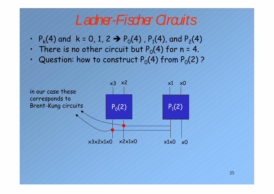
Ladner-Fischer Circuits• Pk(4) and k = 0, 1, 2 � P0(4) , P1(4), and P2(4)• There is no other circuit but P0(4) for n = 4.• Question: how to construct P0(4) from P0(2) ?
P0(2)
x2x3in our case thesecorresponds to Brent-Kung circuits P1(2)
x0x1
x0x1x0x2x1x0x3x2x1x0

26
(g0, p0)
P0(4) Circuit for Carry Calculation(g1, p1)(g2, p2) (c0, 1)
(c0, 1)(c1, p0)(c2, p1 p0)(c3, p2 p1 p0)
Brent-Kung Circuit

27
General Construction Scheme for P0(n)
0
P1(n/2)
1n/2-1
P0(n/2)
n/2n-1

28
General Construction Scheme for P1(n)
P0(n/2)
012345n-1 n-2

29
P0(8)
P0(4)
0
P1(4)=P0(4)
1347 25676
5432
10
6543
210
5432
10
4321
0
3210 210 10 0
0 � (c0, 1)1 � (g0, p0)2 � (g1, p1)3 � (g2, p2)…7 � (g6, p6)
10 � (c1, p0)210 � (c2, p1p0)3210 � (c3, p2p1p0)…7 � 210� (c7, p6 … p1p0)

30
P1(8)
P0(4)
0123457 6

31
Assignment• Construct CLA adders of 4-bit, 8-bit, 16-bit,
32-bit, and 64-bit using structural VHDL modeling.1. create a behavioral model of Brent-Kung circuit.2. construct P0(2)3. construct P0(4) using P0(2)4. construct P0(8) using P0(4)5. construct P1(8) using P0(4)6. construct P0(16) using P0(8) and P1(8) 7. construct P1(16) using P0(8)8. construct P0(32) using P0(16) and P1(16)9. construct P1(32) using P0(16)10. construct P0(64) using P0(32) and P1(32)

32
Hierarchy of Models
full_adder.vdh
or2.vdh
half_adder.vdh
and2.vdh xor2.vdh
Hierarchy of models used in the full adderAt lowest level, a behavioral description must exist

33
Structural Model of a Half Adderarchitecture structural of half_adder is
component xor2 isport (x,y: in std_logic;
z: out std_logic);end component xor2;
component and2 isport (x, y: in std_logic;
z: out std_logic);end component and2;
beginEX1: xor2 port map(x=>x, y=>y, z=>sum);
AND1: and2 port map(x=>x, y=>y, z=>carry)
end architecture structural;
• There may be a many levels of hierarchy in structuralmodel.
• No behavioral description.

34
Flattening• When the simulator loads the hierarchy of
structural model, it replace each component by its behavioral description.– This process is repeated at each level hierarchy.
• This is called as flattening of hierarchy.• Flattening of the all hierarchy may result in a
very complicated behavioral description of a very complex design.– Simulation may take too long– Preserving hierarchy in a structural model is a way
of managing very complex systems.– Components can be simulated in isolation.

35
Parameterized Models• Aim: to construct parameterized models.
– You use 5 ns delay for your 2-input and gates in your model.
– Thanks to developments in the technology, you would like to simulate your model using 1 ns propagation delay for your 2-input and gates.
– It is hard to change the delay of every 2-input gate delay manually.
– Solution: to be able to decide delay values at simulation time rather than design time.
• Parameterized models are useful in creating libraries of models that can be shared and reused.

36
Genericslibrary IEEE;use IEEE.std_logic_1164.all
entity xor2 isgeneric(gate_delay: Time:= 2ns);
port(x, y: in std_logic;z: out std_logic);
end entity xor2;
architecture behavioral of xor2 isbeginz <= (x and y) after gate_delay;
end architecture behavioral;
– The default delay for xor2 gate is 2 ns.
– The gate delay can be specified at the time of its use.
xor gate is defined with generic

37
Generics
architecture structural of half_adder is
component xor2 isgeneric(gate_delay: Time);port (x,y: in std_logic;
z: out std_logic);end component xor2;
component and2 isgeneric(gate_delay: Time:=3 ns);port (x, y: in std_logic;
z: out std_logic);end component and2;
beginEX1: xor2 generic map(gate_delay => 6 ns)
port map(x=>x, y=>y, z=>sum);
AND1: and2 port map(x=>x, y=>y, z=>carry)
end architecture structural;

38
Specifying Generics Constants1. in the component declaration
component and2 isgeneric(gate_delay: Time:=3 ns);port (x, y: in std_logic; z: out std_logic);
end component and2;
2. in the component instantiationEX1: xor2 generic map(gate_delay => 6 ns)
port map(x=>x, y=>y, z=>sum);
• If both specified, the value provided in the component instantiation takes precedence.
• If none is specified, the default value defined in the entity is used.

39
Passing Generic Values through Hierarchylibrary IEEE;use IEEE.std_logic_1164.all
entity half_adder isgeneric(gate_delay: Time:= 3ns);port(a, b: in std_logic; sum, carry: out std_logic);end entity half_adder;
architecture structural of half_adder is
component xor2 isgeneric(gate_delay: Time);port(x, y: in std_logic; z: out std_logic);end component xor2;
component and2 isgeneric(gate_delay: Time);port(x, y: in std_logic; z: out std_logic);end component and2;
begin
EX1: xor2 generic map(gate_delay=>gate_delay)port map(x=>a, y=>b, z=>sum);
A1: and2 generic map(gate_delay=>gate_delay)port map(x=>a, y=>b, z=>carry);
end architecture structural;

40
Passing Generic Values through Hierarchy...H1: half_adder generic map(gate_delay => 6 ns)
port map(a => in1, b => in2, sum => s1, carry=>s2);H2: half_adder ......
...EX1:xor2 generic map
(gate_delay=>gate_delay)...
A1:and2 generic map(gate_delay=>gate_delay)
...EX1:xor2 generic map
(gate_delay=>gate_delay)...
A1:and2 generic map(gate_delay=>gate_delay)
entity xor2 isgeneric(gate_delay: Time:= 2ns);--...
entity and2 isgeneric(gate_delay: Time:= 2ns);...
6 ns6 ns 6 ns6 ns
6 ns 6 ns
The generic value coming from the upper level of hierarchy overrides the other values.
full_adder.vhd
half_adder.vhd
xor2.vhd and2.vhd

41
N-input AND Gateentity and_gate isgeneric(n:natural:=2);port(x: in std_logic_vector(n-1 downto 0);
z: out std_logic);end entity and_gate;
architecture generic of and_gate is
beginprocess(x)
variable and_out:=‘1’;begin
and_out <= ‘1’; --on an input signal transition it must be set to 1for i in 1 to n loop
and_out := and_out and x(i);exit when and_out = ‘0’;
end loop;z <= and_out;
end process;
end architecture generic;
entity or_gate isgeneric(m:integer:=2);port(x: in std_logic_vector(m downto 1);
z: out std_logic);end entity or_gate;

42
Another Exampleentity another_gen_ex isend entity another_gen_ex;
architecture generic of another_gen_ex is-- component declaration for the gatescomponent and_gate isgeneric(n:natural:=5);port(x: in std_logic_vector(n-1 downto 0); z: out std_logic);end component;
component or_gate isgeneric(m:integer);port(x: in std_logic_vector(m downto 1); z: out std_logic);end component;signal s1, s2, s3, s4: std_logic;signal sa: std_logic_vector(1 to 5);signal sb: std_logic_vector(2 downto 1);signal sc: std_logic_vector(1 to 10);signal sd: std_logic_vector(5 downto 0);
begin-- component instantiationso1: or_gate generic map(6) port map(sd, s1);a1: and_gate generic map(N => 10) port map(sc, s3);a2: and_gate port map(sa, s4);-- o2: or_gate port map(sb, s2); -- illegal
end architecture generic;

43
N-bit Registerlibrary IEEE;use IEEE.std_logic_1164.all;
entity generic_reg isgeneric(n: positive := 2);port(clk, reset, enable: in std_logic;
d: in std_logic_vector(n-1 downto 0);q: out std_logic_vector(n-1 downto 0));
end entity generic_reg;
architecture behavioral of generic_reg is
begin
reg_process: process(clk, reset) isbegin
if reset = ‘1’ thenq <= (others => ‘0’);
elsif (rising_edge(clk)) thenif enable = ‘1’ then
q <= d;end if;
end if;end process reg_process;
end architecture behavioral;
Note the statement q <= (others => ‘0’);

44
Trace of the Operation of a 2-bit Register

45
Component Instantiation & Synthesis• Structural design
– The ability to instantiate specific components enables us to use previously synthesized and optimized implementation of common components
– Those implementation may be provided by the vendors, other design groups, or by yourself from a previous design.
– Performance critical components may be manually placed and routed to a specific target device.
– Manual place-and-routing is time-consuming.– Such components may be provided by vendors in
design libraries

46
Core Generators• A CAD tool
– allow you select and then configure the components of your choice.
– The CAD tool will then generate a synthesizeable model of this component and corresponding VHDL model.
– The CAD tools generally do a good job of producing models that will generate highly optimized implementations for the target FPGA device.
– The LogiBLOX of Xilinx Foundation is such a tool.

47
Xilinx Foundation LogiBLOX

48
Xilinx Foundation LogiBLOX

49
Xilinx Foundation LogiBLOX

50
addsub8.vhi File------------------------------------------------------
-- LogiBLOX ADD_SUB Module "addsub8"
-- Created by LogiBLOX version E.35
-- on Sun Nov 02 17:37:55 2003
-- Attributes
-- MODTYPE = ADD_SUB
-- BUS_WIDTH = 8
-- OPTYPE = ADD_SUB
-- REGISTERED = NONE
-- ENCODING = SIGNED
-- STYLE = MAX_SPEED
------------------------------------------------------
----------------------------------------------------

51
addsub8.vhi File-- Component Declaration
----------------------------------------------------
component addsub8
PORT(
ADD_SUB: IN std_logic;
C_IN: IN std_logic;
A: IN std_logic_vector(7 DOWNTO 0);
B: IN std_logic_vector(7 DOWNTO 0);
SUM: OUT std_logic_vector(7 DOWNTO 0);
OVFL: OUT std_logic;
C_OUT: OUT std_logic);
end component;
----------------------------------------------------
-- Component Instantiation
----------------------------------------------------
instance_name : addsub8 port map
(ADD_SUB => ,C_IN => , A => , B => , SUM => , OVFL => ,C_OUT => );

52
Xilinx Foundation LogiBLOX• Caveat: Since we do not have the license,
LogiBLOX will only provide the model in EDF format.
• In the previous example, EDF format is saved in addsub8.EDO file.