fuel oil system
DESCRIPTION
about fuel oil systemTRANSCRIPT

4.0 FUEL OIL SYSTEM1. DEFINITION
Fuel oil is a fraction obtained from petroleum distillation, either as a distillate or a residue. Broadly speaking, fuel oil is any liquid petroleum product that is burned in a furnace or boiler for the generation of heat or used in an engine for the generation of power, except oils having a flash point of approximately 40 °C (104 °F) and oils burned in cotton or wool-wick burners. In this sense, diesel is a type of fuel oil. Fuel oil is made of long hydrocarbon chains, particularly alkanes, cycloalkanes and aromatics. The term fuel oil is also used in a stricter sense to refer only to the heaviest commercial fuel that can be obtained from crude oil i.e. heavier than gasoline and naphtha. (1)
Diesel fuel is principally a blend of petroleum-derived compounds called middle distillates (heavier than gasoline but lighter than lube oil) and may or may not contain additional additives. Other middle distillates include kerosene and No. 2 Heating Oil. Diesel fuel is designed to operate in a diesel engine where it is injected into the compressed, high-temperature air in the combustion chamber and ignites spontaneously. This differs from gasoline, which is ignited in a gasoline engine by the spark plugs.
2. DISTRIBUTION AND DELIVERY
a. Road delivery vehiclesVehicles make deliveries of oil fuels by road with capacities ranging from 11,800 to 28,700
liters (2600 to 6300 gallons). The vehicles discharge fuel into customers’ storage by pump or compressed air at rates up to 1050 liters (230 gal) per minute, and can deliver to a height of 10.7 meters (35 ft) above the vehicle.
Truck trailers can usually drop 11,300 – 19,900 liters at a delivery. (Morse, pg. 170).Truck tank cars will deliver from a few hundred gallons up to their capacity of about 6000
gal. (Potter, pg. 590).b. Rail tank cars
The capacities of rail tank cars are generally 45 tons gross laden weight (approx. 30 tons payload) to 100 tons gross laden weight (approximately. 70 tons payload). Cars for carrying
1

heated fuel oil are insulated with fiberglass lagging covered with galvanized sheeting, and are equipped with finned tubes for steam heating.
Railway tank cars vary from 30,300 to 45,400 liters in capacity. (Morse, pg. 170).When delivered by railroad tank car, there must be on hand at least sufficient storage
capacity to accommodate the capacity of one car (6000 to 10,000 gal) plus a minimum operating supply. If delivery should be erratic, a larger minimum capacity will be necessary. (Potter, pg. 590).
c. River and coastal tankersWhere a customer has suitable berthing facilities and satisfactory arrangements can be
made, deliveries can be by either river or coastal tanker. River tankers currently in use are of 1860 tons capacity but may be larger if conditions permit. The customer is responsible for supplying oil hose and/or discharge arms capable of discharging the full contents of the barge under low-water conditions.
Coastal tankers are available up to 2000 tons capacity, equipped with pumps for discharging into customer’s storage. The size of the vessels to be used will depend upon local conditions and the depth of water in the approaches.
3. STORAGE TANKS3.1 Types of Storage Tanks by location
3.1.1 Aboveground TanksStorage tanks should, wherever possible, be installed above ground. The site
selected should not be in an unduly exposed position. Clearance must be allowed for the withdrawal from the tank of fittings such as immersion heaters and steam coils. Where tanks are installed inside buildings, they should generally be located within a tank chamber, although in some industrial installations such as steelworks and foundries, a tank chamber may not be necessary. The requirements of insurance companies and local authorities should be considered when designing these installations.
Above ground storage tanks pose a fire hazard with the risk of fire spreading to other facilities in the vicinity. Therefore these tanks have to be installed at a minimum specified distance from other facilities. In order to contain spills and leakages dikes have to be built around above ground storage tanks.(2)
3.1.2 Underground TanksWhere underground installation of a storage tank is unavoidable, it should
preferably be housed in a specially constructed brick or concrete chamber, allowing easy access to the drain valve and other fittings. Wherever possible, the tank chamber should be located in dry ground and the finished structure made watertight. A sump must be provided in the floor of the chamber stone and to collect any water that may enter the chamber in exceptional circumstances, and the floor should slope slightly downwards towards the sump. Water collected in the sump can be removed by using a semi-rotary pump. The lower part of the chamber should form an oil resistant catch pit, as with the more usual aboveground storage tank.
2

3.1.3 Buried TankIt is recommended that storage tanks should not be buried directly in contact with
soil, since it is almost impossible to avoid corrosive attack. Where, for some reason, it is not possible to provide a tank chamber as already described, adequate corrosion protection must be applied to all exterior surfaces of the tank, fittings and pipework.
Underground storage tanks are more costly to install but have a longer life because they are shielded from the environment. Underground storage tanks can be constructed from fiberglass-reinforced plastic. Such tanks are usually ribbed so as to provide structural strength. Alternately, underground storage tanks can be fabricated from steel but with appropriate cathodic protection against corrosion from ground water. Likewise, piping from the underground storage tank to the generator can be of fiberglass-reinforced plastic or cathodically protected steel. (2)
3.1.4 Bunded AreaWhere overfilling or leakage from the tank would contribute to a fire hazard, cause
damage to property or contaminate drains or sewers, a bund wall should be constructed around the tank. This should be of brick or concrete with an oil-tight lining, and sealed to the concrete base under the tank supports. The capacity of the bunded area should be at least 10 per cent greater than that of the storage tanks contained within it.
3

Fuel storage tanks and handling facilities are generally either underground (UST) or aboveground (AST) storage tank systems. An UST is any one or combination of tanks or tank systems defined in applicable Federal or State regulations as an UST. Typically (unless otherwise provided by applicable Federal or State rules), an UST is used to contain a regulated substance (such as a petroleum product) and has 10 percent or more of its total volume beneath the surface of the ground. The total volume includes any piping used in the system. An UST may be a buried tank, or an aboveground tank with buried piping if the piping holds 10 percent or more of the total system volume including the tank. For purposes of this part, an aboveground storage tank (AST) is any storage tank whose total volume (piping and tank) is less than 10 percent underground or any storage tank defined by applicable law or regulation as an AST. (3)
3.1.5 Sub Base TanksIf you need to store less than 1,000 gallons of fuel, you would need sub base tanks.
As the name suggests, sub base tanks are designed to fit above the ground but below the base of the generator set.(2)
Sub base tanks are rectangular in cross section and are double walled tanks. This helps to prevent spillage of fuel in case of leakage.(2)
3.2 Types of Storage Tanks by materialThere are five main types of storage tank available for industrial and commercial fuel oils,
namely:Mild steel weldedMild steel sectionalCast iron sectionalFiberglass reinforced plastic (FRP)Reinforced concrete
Of these five, the mild steel welded tank is the most popular and is widely used for every type of application.
The majority of storage tanks are of the horizontal cylindrical type, as shown in Figure 2. Where ground space is a limiting factor, vertical cylindrical tanks may be used.
4

3.3 Other TypesA. Single or Double Wall ConstructionB. Cylindrical or Rectangular ShapesC. Horizontal or Vertical
3.4 CapacitiesThe capacity of storage tanks for oil-fired installations is an important consideration. The
minimum net storage capacity should be calculated either by taking:1. Three weeks’ supply of oil at the maximum rate of consumption; or2. Two weeks’ supply at the maximum rate of consumption, plus the usual capacity ordered for
one delivery, whichever is the larger.Where the maximum weekly off-take is less than 200 gallons (1810 liters) the capacity
should still not be less than 650 gal (21850 l) in order to accept a standard 500-gal (2270-l) tanker delivery. In some circumstances, it may be desirable to provide more than one tank, each of sufficient capacity to accept at least a full delivery.
For the purposes of sizing storage tanks, it may be considered that a gallon of fuel oil will generate 10 kwhr. There are 42 gal per barrel. Some engineers believe that there should be two storage tanks so that one may be cleaned or inspected while the other is in operation. Horizontal tanks may be used up to 30,000-gal capacity. Day-tank capacities should be sufficient for about 8 hr operation of the engine (one shift). (Potter, pg. 590).
3.5 Tank supportsHorizontal cylindrical tanks should be installed on brick or reinforced concrete cradles with a
downward slope of 1 in 50 from the draw-off end towards the drain valve, as shown in Figure 2. Cradles should be constructed on foundations adequate for the load being supported and the type of soil. A reinforced concrete raft equal to the plan area of the tank, and of adequate
5

thickness to bear the load, is normally suitable for all but the weakest soils. Cradles should not be placed under joints or seams of the tank plates and a layer of bituminized felt should be interposed between the cradle and tank. The height of the tank supports should provide at least 450mm space between the drain valve and ground level to allow access for painting or draining the tank.
3.6 Tank Fittings3.6.1 Oil-level indicators
A brass dipstick is recommended as a cheap and reliable means of determining the contents of a storage tank. A dipstick, when required, is usually provided ready calibrated by the tank manufacturer before installation of the tank.
In many cases it is inconvenient to use a dipstick, due to the position or location of the tank, and there are a variety of direct and remote contents gauges available, including gauge glasses, float and weight, float and swing arm, float and indicator, hydrostatic, electrical capacitance, etc.
3.4.2 Filling connectionFilling pipes should be as short as possible and free from sharp bends. The terminal
should be in a convenient position to allow easy coupling of the vehicle hose connection, wherever possible within 5 meters (15 ft) of the hard standing for vehicle delivery. The most suitable height for a filling pipe is about 1m (3 ft) above ground level and clear of all obstructions.
3.4.3 UllageThe air space between the oil surface and the top of the tank is known as ullage;
there should always be a small ullage remaining when the contents gauge registers full. This prevents the discharge of oil from the vent pipe due to any frothing and surging of the liquid during delivery. The ullage should provide not less than 100mm (4 in) between the oil surface and the top of the tank or be equivalent to 5 per cent of the total contents, whichever is the greater
3.6.4 Vent pipesA vent pipe must be fitted at the highest point of every storage tank. Wherever
possible, it should be visible from the filling point and terminate in the open air, in a position where any oil vapor will not be objectionable and, in the event of an overflow, there will be no damage to property, fire risk of contamination of drains.
The vent pipe bore must be equal to or greater than the bore of the filling pipe, and never less than 50 millimeters (2 in) diameter. It should be as short as possible and free from sharp bends. It should terminate in a return bend or ‘goose neck’ fitted with a wire cage for protective purposes (fine gauze must never be used for this purpose).
3.6.5 Draw-off connectionThe draw-off connection to the oil-burning plant should be at the raised end of
horizontal tanks. Where heating facilities are not provided, the lowest point of the draw-off connection should never be less than 75mm (3 in) above the bottom of the tank. For tanks fitted with heating elements, it is essential that these and their associated thermostatic control probes should always remain below the oil surface.
6

3.6.6 Drain valveA screw-down gate valve with a bore similar to that of the draw-off connection
should be installed at the lowest point on every storage tank to permit complete draining. The valve should be readily accessible with a clear space below to facilitate its use. Extension pipes to or from drain valves should be avoided if possible, but where these are necessary, the pipe should be lagged and, if necessary, traced to ensure that residual grades of oil will flow during adverse weather conditions. Valves and extension pipes should be fitted with a plug or blank flange to prevent inadvertent discharge of the tank contents.
3.6.7 ManholeEvery storage tank must have a manhole in an accessible position, preferably on
top. It may be circular, oval or rectangular, and not less than 460mm (18 in) diameter if circular or 460mm (18 in) long and 410mm (16 in) wide if oval or rectangular. The manlid must be securely fixed by bolts, studs or setscrews, and have a liquid and vapor-tight joint. Close-woven proofed asbestos, graphited on both sides, is a suitable jointing compound for this purpose.
Vertical tanks over 3.65 meters (12 ft) high should have a further manhole fitted near the bottom to provide access for cleaning and maintenance of any storage heating facilities.
3.7 Heating RequirementsDistillate grades of oil fuel may be stored, handled and atomized at ambient temperatures,
and do not require heating facilities to be provided in storage tanks and handling systems. However, exposure to extreme cold for long periods should be avoided, since oil flow from the tank may become slightly restricted.
Heating facilities are required for all residual grades of oil fuels, such as Light Fuel Oil, Medium Fuel Oil, and Heavy Fuel Oil. Table 1 gives the recommended minimum storage and handling temperatures for residual oil fuels (from BS 28618: 11870).
7

Where oil is to be maintained at minimum storage temperature, an outflow heater will be necessary to raise the temperature of the oil leaving the tank to that required for handling. It is not good practice to store oil fuel at unnecessarily high temperatures, and the temperature given under the column ‘Minimum temperature at outflow from storage and for handling’ should not be exceeded by more than 16.7°C (30°F). This is particularly important in relation to Light Fuel Oil.
Maximum heat losses from storage tanks can be determined from Table 2. These losses can be translated into maximum steam consumption rates of the heating coils from knowledge of the latent heat of steam appropriate to the steam pressure used in a given installation. The tank heating arrangements must be capable of maintaining the oil storage temperature with the appropriate rate of heat loss.
Table 2. Heat loss from sheltered and exposed, lagged and unlagged oil tanks (www.engineeringtoolbox.com).
Heat loss(W/m2.K)
(Btu/hr-ft2-F)
Oil temperatureUp to 10 CUp to 50 F
10 – 27 C50 – 80 F
27 – 38 C80 – 100 F
UnlaggedSheltered 6.8
1.27.41.3
8.01.4
Exposed 8.01.4
8.51.5
9.01.6
LaggedSheltered 1.7
0.31.8
0.322.0
0.35
Exposed 2.00.35
2.10.37
2.250.4
3.8 Heating MethodsStorage tanks can be heated with thermostatically controlled steam coils, hot-water coils,
electric immersion heaters or a combination of these. The elements and their thermostats should be positioned below the level of the oil draw-off line, so that they are always covered during normal operation. The temperature-sensitive element of the thermostat should always be situated above and to one side of the heating element. The heating elements should be spaced evenly over the bottom of the tank or concentrated towards the draw-off end. A combination of steam and electric heating can be used for installations where periods may occur during which steam is not available.
Where a residual oil fuel is stored in tanks with outflow heaters provision should also be made to maintain the oil at or above the minimum storage temperature shown in Table 1. Excessive heating is not recommended, particularly for Light Fuel Oil, and will increase running costs unnecessarily. Additional heating to outflow heaters can be provided by using a steam, hot water or electric heater running along the bottom of the tank. With electric heating, additional separate heating elements may be required.
Heating elements should be readily removable for repair if necessary and consequently careful note should be taken of possible external obstructions to this operation. The steam
8

supply to the heating coils should be dry saturated. It is not generally necessary for the pressure to exceed 3.45 bar (50 lbf/in2). The temperature of the heating medium should not exceed 177°C (350°F), and electric element loading should not exceed 1.24 W/cm2 (8 W/in2).
3.9 Heating requirements for warming storage tanks
The hourly heat requirement (Q ) to raise the temperature of storage tank can be calculated from:
Q=W×c p×t rwhereW = total weight of contents when full (kg (lbs)),c p= mean specific heat of fuel oil,t r = temperature rise required per hour (°C (°F)).
The following are specific gravity and specific heat of fuel oil / diesel oil.
Table 3. Specific gravity and specific heat of fuel oil / diesel oil.Reference: Armstrong Steam and Condensate Group, www.armstrong-intl.comFuel Specific Gravity @ 60-70 F Specific Heat @ 60 F,
Btu/lb-FSpecific Heat @ 60 F, kJ/kg-C
No. 1 Fuel Oil 0.81 0.47 1.9679No. 2 Fuel Oil 0.86 0.44 1.8423No. 3 Fuel Oil 0.88 0.43 1.8004No. 4 Fuel Oil 0.90 0.42 1.7585No. 5 Fuel Oil 0.93 0.41 1.7167No. 6 Fuel Oil 0.95 0.40 1.6748
The rate of temperature rise (t r ) will depend on the particular circumstances of the installation and on how quickly the contents of the tank must be brought up to temperature.
3.10 Lagging / InsulationVarious types of lagging are available. The major advantage of its use is a considerable
reduction in heat losses from both storage tanks and pipework. The materials most suitable for application to storage tanks are in the form of blankets or molded sections, glass silk blankets of 85 per cent magnesia or slagwool. When applied, these materials should provide a lagging efficiency of approximately 75 per cent. All lagging should be reinforced with wire netting, either incorporated into the blanket or secured to anchor points on the tank surface. A weatherproof surface finish should finally be applied to the lagging. This can be either two-ply bitumen felt or, if necessary, sheets of galvanized steel or aluminum with sealed joints.
9

4. PIPEWORK SYSTEM4.1 Handling Temperatures
Oil fuel pipeline systems transfer oil from storage to the oil burner at specified conditions of pressure, viscosity, temperature and rate of flow. There can be considerable variety in the choice of system, but its design (particularly correct pipe sizing and temperature control) is most important if it is to function satisfactorily.
Distillate grades are usually handled at ambient temperatures provided these are not below the cloud point when using gas oil. Residual grades, on the other hand, are handled at temperatures above ambient. The recommendations of Table 1 should always be followed regarding minimum recommended handling temperatures. Residual grades can also be handled at temperatures above those recommended as minimum handling levels in order to reduce oil viscosity, improve regulation and control of oil flow, reduce friction losses in pipelines and, when necessary, provide oil at the correct atomizing temperature for the oil-burning equipment.
4.2 Handling equipmentTwo items of equipment should always be inserted in the handling system as close to the
storage tank as possible. These are a filter and a fire valve.To prevent foreign matter from damaging components and choking valves or atomizer
orifices, filters must be incorporated into the handling system. There are usually two stages of filtration. The first provides protection for pumps and fire valves which handle oil at temperatures below those required at the oil-burning equipment. Second-stage filtration protects the atomizer orifice and burning equipment, and is sometimes incorporated as part of the burner assembly.
The filtering medium should be of corrosion-resistant material such as Monel metal, phosphor-bronze or stainless steel. All first-stage filters should be provided with isolating valves.
Fire valve is a valve that closes in case of fire should be inserted in the oil fuel line to the oil-burning equipment and fitted as close to the tank as possible. It may be held open mechanically, pneumatically or electrically. Temperature sensitive elements should be arranged to close the valve at a fixed maximum temperature, and sited close to the oil-fired plant and well above floor level. The operating temperature of the heat-sensitive elements should not be greater than 68°C (155°F) except where ambient temperatures in the vicinity of the plant may exceed 418°C (120°F), in which case the operating temperatures may be 183°C (200°F).
4.3 Types of systemThere are two main types of oil-handling system in common use. These are gravity and ring
main.
4.3.1 Gravity systemsGravity systems are of three basic types: gravity, pump assisted gravity and sub-
gravity. Gravity systems in general will handle distillate grades at ambient temperatures,
and residual oils at pumping or atomizing temperatures. Lagging and tracing will be required with residual grades to prevent cooling of the oil to below handling temperatures.
10

4.3.1.1 Gravity systemA gravity system is one in which the oil flows directly from the storage or
service tank through gravity feed pipeline. The static head on the feed line will vary with the depth of oil in the tank, and the system should therefore only be used for burners which will operate satisfactorily between such limits.
4.3.1.2 Pump-assisted gravity systemA pump-assisted gravity system is one in which oil flows by gravity from the
storage or service tank to a pump. The pump supplies oil to the combustion equipment through a pipeline passing only the quantity required to feed the oil-firing equipment. The inclusion of a pump in this system will not reduce the static head due to the fuel supply in the tank. The working pressure required at the oil-burning equipment should therefore be greater than the maximum static head available when the storage or service tank is full.
4.3.1.3 Sub-gravity systemA sub-gravity system is one in which a pump associated with the oil-burning
equipment is used to suck the oil from a tank in which the level of the oil can be below the level of the pump.
4.3.2 Ring main systemsA ring main system draws oil from storage and circulates it to each consuming point
in turn, the balance of the oil being returned either to the suction side of the circulating pump or to storage. A diagram of a typical hot oil ring main system is shown in Figure 2.
Each take-off point is connected to the burner it supplies by a branch line. Pressure conditions are maintained approximately constant at each take-off point by a pressure-regulating valve situated after the last takeoff point, and circulating a quantity of oil one and a half to three times the maximum take-off from the circuit. By this means, stopping take-off at one consuming point will not have a marked effect on the pressure at other consuming points. Pressure conditions should be calculated at each consuming point for all conditions of operation and take-off. The bore of the ring main should be such that pressure variations are not excessive for the equipment served. If these variations at each take-off point are likely to be critical, they can be accommodated by the use of individual pressure-regulating valves on each branch.
Ring main systems are of three types: hot oil, warm oil and cold oil. Hot oil ring mains circulate oil at atomizing temperature, warm oil ring mains at a temperature
11

between minimum pumping and atomizing temperature, and cold oil ring mains at ambient temperature.
4.3.2.1 Hot oil ring mainsThis is the most important of the three types of ring main system, since it
offers economies of installation and running costs. The smallest pipe sizes and fittings can be used with low-viscosity high-temperature oil, and the number of line heaters is minimized. The oil is circulated at atomizing temperatures and in consequence, the system is less liable to be affected by pressure fluctuations due to variations in viscosity, or small changes in the viscosity of the oil as delivered. The system should usually be considered as the first possibility and only discarded in favour of warm or cold oil systems where these will give some real advantage.
4.3.2.2 Warm oil ring mainsThis system is similar to a cold oil ring main but includes provision for
heaters in the circuit to maintain oil temperature between minimum handling and atomizing levels. This provides a reduction in oil viscosity and reduces pipe friction. The circulation temperature of the oil should be chosen to give the minimum pressure drop consistent with the system design when circulating one-and-a-half to three-times the maximum take-off and using a suitable pipe diameter. This circulation temperature should allow a reasonable margin below the specified atomizing temperature to facilitate the selection of the necessary line heaters for branch lines between the ring main and the oil-burning equipment.
4.3.2.3 Cold oil ring mainsThis system is used mainly where different atomizing temperatures are
required at various consuming points or where a branch line would be unacceptably long. The system should only be used where the length of pipeline involved and the quantity of oil circulated will not cause an excessive pressure drop due to friction. When designing a cold oil ring main system, care must be taken to ensure that the pressure variations between take-off points, due to changes in the oil consumption rate, do not affect burner performance. Circulating one-and-a-half to three times the maximum take-off required achieves this. The system is widely used with distillate grades but rarely with residual grades.
4.4 Pipe sizingThe following factors must be taken into account when assessing pressure drop.4.4.1 Viscosity
Pressure drop is directly proportional to viscosity. The effect of heat loss from pipelines and consequent increase in viscosity should also be considered.
12

Table 4. Viscosity of Fuel Oil and Diesel Oil
13

Table 5. Approximate Viscosity Conversion
14

Viscosity Equation:
Kinematic viscos ity , ν=absolute vis cos ity , μdensity , ρ
1 Stoke = 1 cm2/s = 100 cSt1 Poise = 1 g/(cm-s) = 100 cP
Kinematic viscos ity (cSt )=absolute vis cos ity (cP )specific gravity
To convert viscosity from SSU to centistokes:
Centistokes={0 . 226×SSU−195SSU
for 32≤SSU≤100
0 . 220×SSU−135SSU
for SSU>100
To convert viscosity from SSF to centistokes:
Centistokes={2 .24×SSF−184SSF
for 25≤SSU≤40
2 .16×SSF−60SSF
for SSU>40
Example No. 1A crude oil has a dynamic viscosity of 30 cP at 20◦C. Calculate its kinematic viscosity
in SI units. The density is 0.85 gram per cubic centimeter (g/cm3).
15

Given: Dynamic viscosity = 30 cP Density = 0.85 gram per cubic centimetreRequired: Kinematic viscosity in SI units.
Solution:Since the density in g/cm3 is numerically the same as specific gravity,
Kinematic viscos ity (cSt )=absolute vis cos ity (cP )specific gravity
Kinematic viscos ity (cSt )=300 . 85
Kinematic viscos ity (cSt )=35 . 29 cSt
4.4.2 Specific gravityThe specific gravity of a liquid and its API gravity are related by the following two
equations:
SG60=141 .5131 .5+API
The specific gravity SG60 is the value at 60◦F since by definition the API is always at 60◦F. Thus, given the value of API gravity of a petroleum product we can easily calculate the corresponding specific gravity at 60◦F using these equations.
From Design of Machine Elements book by Faires. The specific gravity of a petroleum oil at any temperature t is given approximately by
SGt=SG 60−0 . 00035 (t−60 )
Example No. 2A sample of crude oil when tested in a lab showed an API gravity of 35. What is the specific gravity of this crude oil?
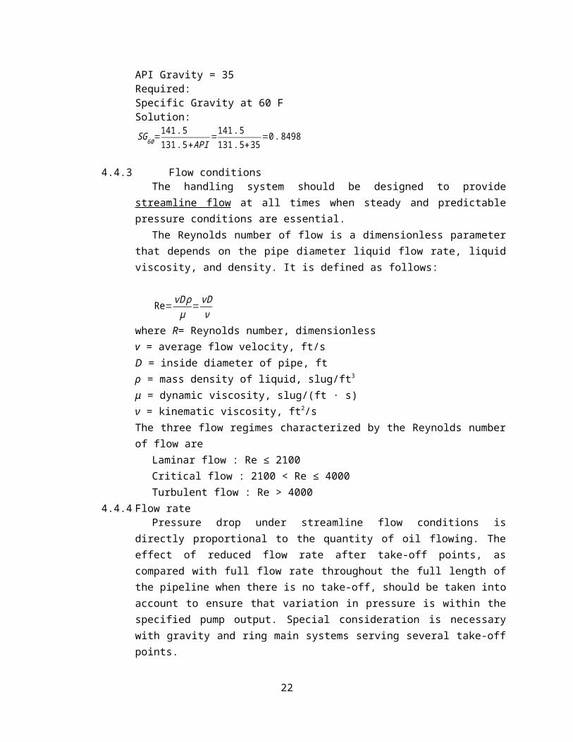
Given:API Gravity = 35Required:Specific Gravity at 60 FSolution:
SG60=141 .5131 .5+API
=141. 5131. 5+35
=0 .8498
4.4.3 Flow conditionsThe handling system should be designed to provide streamline flow at all times
when steady and predictable pressure conditions are essential.The Reynolds number of flow is a dimensionless parameter that depends on the
pipe diameter liquid flow rate, liquid viscosity, and density. It is defined as follows:
16

Re= vD ρμ
= vDν
where R= Reynolds number, dimensionlessv = average flow velocity, ft/sD = inside diameter of pipe, ftρ = mass density of liquid, slug/ft3
μ = dynamic viscosity, slug/(ft · s)ν = kinematic viscosity, ft2/sThe three flow regimes characterized by the Reynolds number of flow are
Laminar flow : Re ≤ 2100Critical flow : 2100 < Re ≤ 4000Turbulent flow : Re > 4000
4.4.4 Flow ratePressure drop under streamline flow conditions is directly proportional to the
quantity of oil flowing. The effect of reduced flow rate after take-off points, as compared with full flow rate throughout the full length of the pipeline when there is no take-off, should be taken into account to ensure that variation in pressure is within the specified pump output. Special consideration is necessary with gravity and ring main systems serving several take-off points.
The Darcy equation may be used to calculate the pressure drop in a pipeline as follows:
h=f LDv2
2gwhere h= frictional pressure loss, ft of liquid headf = Darcy friction factor, dimensionlessL = pipe length, ftD = inside pipe diameter, ftv = average flow velocity, ft/sg = acceleration due to gravity, ft/s2
In laminar flow, the friction factor f depends only on the Reynolds number and is calculated from
f=64Re
where f is the friction factor for laminar flow and Re is the Reynolds number for laminar flow (Re < 2100) (dimensionless).
4.4.5 Length of pipelinePressure drop is directly proportional to the length of the pipeline. All fittings used
in the system should be included in the determination of ‘effective pipeline length’. Table 6 and 7 should be used to determine the equivalent length to be added to the
17

actual length of the pipeline for various types of fitting. The resulting figure is the total ‘effective length’ of the system.
Example No. 3A piping system is 200 ft of 2-in pipe that has two 2-in gate valves, one swing check valve, and four 90◦ standard elbows. Using the equivalent length concept, calculate the total pipe length that will include all straight pipe and valves and fittings.
Given:Piping system = 200 ft2 in pipeTwo 2-in gate valvesFour 2-in elbowsRequired:Total Equivalent Pipe Length
Solution: Using Table 6
18

For 2-in pipe:Two 2-in gate valves = 2 × 1.5 = 3 ftOne 2-in swing check valve = 1 × 19 = 19 ftFour 2-in elbow = 4 x 8.5 = 34 ftTotal for all valves and fittings = 3 + 19 + 34 = 56 ftAdding the 200 ft of straight pipe, the total equivalent length of straight pipe and all fittings is Le = 200 + 56 = 256 ft
4.4.6 Oil Pipes - Recommended Flow VelocitiesFlow velocities in oil pipes should be kept within certain limits
Table 8. Recommended Flow VelocitiesOil Application Oil Flow Velocity
m/s Ft/sSuction lines for pumps < 0.5 < 1.6
Suction lines for pumps at low pressures 0.1 – 0.2 0.3 – 0.65Discharge lines for booster pumps 1.0 – 2.0 3.3 – 6.5Discharge lines for burner pumps < 1.0 < 3.3
4.4.7 Branch linesBranch lines transfer oil from a ring main circuit to the oil-burning equipment.
Where a residual oil fuel is to be used, there will be some cooling of the oil immediately adjacent to the pipe surfaces and this will show as a small increase in viscosity. To keep this variation to a minimum and so prevent any difficulties in atomization at the oil burner, care should be taken over the length and diameter of branch lines. In general, the following empirical formula should be used when designing branch lines for hot residual oils:Length:
7 L<√M (S.I. Units)
L<√M (Imperial Units)where,L = ‘equivalent’ length of branch line in m (ft) M = minimum M oil consumption (l/h (gal/h)).
Internal diameter:D<10 . 4 L (S.I. Units)D<L/8 (Imperial Units)where D is in mm (in).Provision should always be made to isolate and drain branch lines.
19

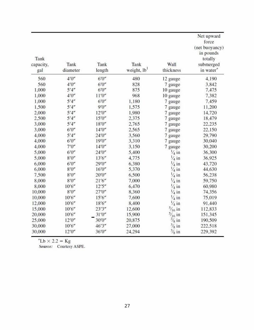
5.0 Dimension and Buoyant Force of Empty Storage Tanks
20

6.0 Typical fire pump fuel storage tank. (Courtesy Fairbanks Morse.)
21
22

7.0 APPROXIMATE FUEL CONSUMPTION
As a rule of thumb for sizing generator fuel oil systems, each 100 kW of generator capacity will consume about 7 gallons per hour. Any oil that is pumped to the engine but is not returned to the day tank would add to the generator capacity based requirement.http://www.preferredutilities.com/documents/Page281_FuelOilHandlingSystemDesign.pdf
23

Figure 6-15 from Power Plant Engineering by F.T. Morse
24

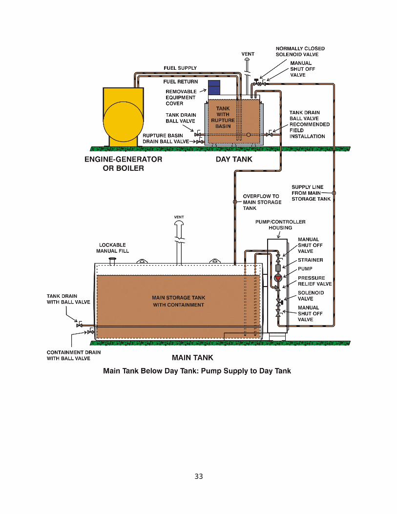
8.0 PIPING DIAGRAMS
25

26
27

9.0 EXAMPLE DESIGN
Design a fuel storage tank and fuel oil piping system for 500 kW generator. Use Diesel No. 2 fuel oil.Pipes and Fittings:Pipe length = 40 m supply, 60 m returnGate Valves = 2 pcs supply, 1 pc returnSwing Check Valve = 1 pcStrainer = 1 pcElbows = as shown
28

Tees = as shownPumping Rate = 2 x Firing RateDetermine:a. Size of Storage Tank. (Dimension). In meters.b. Pipe size.c. Total Pressure drop. In kPa.
Required:a. Size of Storage Tank. (Dimension). In meters.b. Pipe size.c. Total Pressure drop. In kPa.
Solution:Generator Size = 500 kWEach 100 kW of generator capacity will consume about 7 gallons per hour
Full Load Fuel Consumption = (500 kW ) (7 gal /hr per 100 kW )=35 gal /hr
Fuel Oil = No. 2D Diesel Fuel Oil
A. SIZING STORAGE TANK: Three weeks’ supply of oil at the maximum rate of consumption
Capacity of storage tanks = (3 weeks)(7 days/week)(24 hr/day)(35 gal/hr)Capacity of storage tanks = 17,640 gallons. – ans.From Dimension and Buoyant Force of Empty Storage Tanks.
Tank Capacity, gal Tank Diameter Tank Length Wall Thickness15,000 10’6” 23’3” 5/16 in17,640 10’6” x 5/16 in20,000 10’6” 31’0” 5/16 in
29

x=23 . 25+(31. 0−23 .25 )(17 ,640−15 ,00020 ,000−15 ,000 )=27 . 342 ft
x=27 ' 4} {¿D = Diameter = 10’6” = 126 inches = 3.2 mL = Length =27.33 ft = 328 inches = 8.33 mT = Thickness = 5/16 inch = 8 mm Check for volume
V= π4D2 L= π
4(126 )2 (328 )=4 ,089 ,826 in3
V= (4 ,089 ,826 in3 )( 1 gal231 in3 )=17 ,705 gal<17 ,640 gal
Increase tank lengthUllage = 5%
L=(328 in )(17 ,640 gal17 ,705 gal ) (1 .05 )=343 in
Tank Dimension Selected: Diameter = 10’6” = 126 inches = 3.2 mLength =28’7” = 343 inches = 8.5 mThickness = 5/16 inch = 8 mm Ullage = 5%
B. PIPE SIZE :
Table 4. At 30 C (86 F). No. 2 Diesel Fuel OilViscosity = 50.6 SSU
cSt=0. 226×SSU−195SSU
cSt=0. 226×50. 6−19550 .6
=7 . 582 cSt
Table 3. Specific Gravity of Diesel Fuel oil No. 2 at 60 FSp. Gr. = 0.86At 30 C = 86 FSGt=SG 60−0 .00035 (t−60 )SGt=0 . 86−0 . 00035 (86−60 )=0 . 8509
Kinematic viscos ity (cSt )=absolute vis cos ity (cP )specific gravity
7 . 582=absolute viscos ity (cP )0 .8509
30

Absolute vis cos ity (cP )=6 . 452 cP
Select pipe size by trial and error method by limiting Re < 2100 and V < 0.5 m/s.
Try pipe size = ½ in. Sch. 40
O.D. = 0.84 in = 21.336 mm = 0.021336 m
I.D. = 0.622 in = 15.7988 mm = 0.0157988 m
Flow rate = Pumping Rate = 2 x 35 gal/hr = 70 gal/hr
Q= (70 gal /hr ) (231 in3 /gal )( 1 ft12 in )
3
( 1 m3 .281 ft )
3
( 1 hr3600 s )=0 . 0000736 m3 /s
Velocity:
V= 4QπD2
V=4 (0 .0000736 )π (0 .0157988 )2
=0 .3754 m /s<0 .5 m /s
Reynolds Number:
Re=VDν
ν=7 .582 cSt=7 . 582×10−6m2/s
Re=(0 . 3754 ) (0 .0157988 )
7 .582×10−6 =782<2100
Therefore use Pipe size of ½ in. Schedule 40.
C. TOTAL PRESSURE DROP
Return Flow Rate = 35 gal/hr = 35 gal/hr
31

Q= (35 gal /hr ) (231 in3 /gal )( 1 ft12 in )
3
( 1 m3 .281 ft )
3
( 1 hr3600 s )=0 . 0000368 m3 /s
Velocity:
V= 4QπD2
V=4 (0 . 0000368 )π (0 .0157988 )2
=0 .1877 m/ s<0 . 5 m /s
Reynolds Number:
Re=VDν
Re=(0 . 1877 ) (0 . 0157988 )
7. 582×10−6 =391<2100
Supply Line Equivalent Pipe LengthItem Equivalent Length /
unit, mQuantity Equivalent Length, m
Pipe 40 1 40Gate Valves 0.2 2 0.4Swing Check Valves 2.4 1 2.4Strainer 1.5 1 1.5Elbows 1.1 2 2.2Tee, Branch Flow 1.3 1 1.3
Total 47.8 m
Return Line Equivalent Pipe LengthItem Equivalent Length /
unit, mQuantity Equivalent Length, m
Pipe 60 1 60Gate Valves 0.2 1 0.2Elbows 1.1 2 2.2Tee, Branch Flow 1.3 1 1.3Tee, Line Flow 0.5 1 0.5
Total 64.2 m
Pressure Drop for Supply Line
h=f LDV 2
2gFor Laminar Flow
f=64Re
=64782
=0. 082
V=0.3754 m/ s
32
L=47 . 8 mD=0.0157988 m
h=(0 .082 )(47 . 80 .0157988 )[ (0 .3754 )2
2 (9. 81 ) ]=1 .782 m
Δps=SGt ρw gh=(0 .8509 ) (1000 kg /m3 ) (9 . 81 m / s2 ) (1 .782 m )=14 ,875 Pa=14 .9 kPa
Pressure Drop for Return Line
h=f LDV 2
2gFor Laminar Flow
f=64Re
=64391
=0.164
V=0. 1877 m /sL=64 .2 mD=0.0157988 m
h=(0 .164 )(64 .20 .0157988 )[ (0 . 1877 )2
2 (9 .81 ) ]=1. 197 m
Δpr=SGt ρw gh=(0 . 8509 ) (1000 kg /m3 ) (9 . 81 m / s2 ) (1 . 197 m )=9 ,992 Pa=10 .0 kPaTotal Pressure Drop = p = 14.9 + 10.0 = 24.9 kPa
10.0 EXAMPLE DESIGN A Diesel plant will have one 775-kw and two 400-kw units. Delivery of the fuel is to be arranged on a monthly basis, the vendor expecting to deliver by tank car. Expected plant capacity factor, 35%. The tankage and transfer system will be sized. Generator Efficiency = 94 %. Density of fuel oil = 0.9 kg per Liter.Figure 6-15 from Power Plant Engineering by F.T. Morse
33

Given:Diesel plant units - one 775-kw and two 400-kw units.Fuel Delivery – Monthly Basis.Expected plant capacity factor, 35%.Generator Efficiency = 94 %.Density of fuel oil = 0.9 kg per Liter.
Required:Tank size and Transfer pump size.
Solution:
SIZING TANKAGE:
Plant Capacity = 775 + 400 + 400 = 1575 kW.Average output at 35 % load factor = 0.35(1575) = 550 kwFrom Figure 6.15 (above) , greatest fuel consumption at 35% capacity factor = 1.72 kw per litre oil.Lowest fuel consumption at 35% capacity factor = 2.64 kw per litre oil.
Average fuel consumption at 35% capacity factor = (1/2)(1.72 + 2.64) = 2.18 kw per litre oil.
Required Storage = (550
2.18 ) (24 ) (30 )=181 ,650 L - ans.
34

Therefore, use 5 tank cars of 36,330 L capacity.This is equal to (36,330 L)(0.9 kg/L) = 32,697 kg = 72,100 lb = 36 tons tank cars.
SIZING TRANSFER SYSTEM:At full-rated load, fuel consumption (Figure 6.15 above) = 0.18 kg per bhp-hr.
bhp=1575 kw(0.746 kw /bhp ) (0 . 94 )
=2246 bhp
Maximum rate of fuel usage = 2246 x 0.18 = 404.3 kg/hr
Flow rate =
404 .3 kg/hr0. 9 kg/L
=449 . 2 L/hr=7 .5 L/ min
Transfer pumps and piping should have at least 7.5 L/min. – ans.
REFERENCES:Menon, E.S. Piping Calculations Manual. McGraw Hill, 2005.Mobley, R.K. Plant Engineering Handbook. Butterworth Heinemann. 2001Morse, F.T. Power Plant Engineering in MKS Unit, Litton Educational Publishing, Inc. 1953Potter, P.J. Power Plant Theory and Design, 2nd Ed. New York. The Ronald Press Company. 1959Internet:
1. http://en.wikipedia.org/wiki/Fuel_oil 2. http://www.dieselserviceandsupply.com/Generator_Fuel_Tanks.aspx 3. http://www.law.cornell.edu/cfr/text/18/1304.405
35