ftsg resolutions - 2006 (2012) resolutions2012version.pdf · ftsg resolutions 10/04/12 page 1 of 92...
TRANSCRIPT
FTSG Resolutions 10/04/12 Page 1 of 92
FTSG RESOLUTIONS
This document of FTSG resolutions was issued by the Company Secretary 2
nd May 2006.
TABLE OF CONTENTS
No. 1 Moisture Content ...........................................................................................................................3 No. 2 Moisture Content Limits .................................................................................................................4 No. 3 Moisture Content ...........................................................................................................................5 No. 4 Measurement of moisture content of timber ..................................................................................6 No. 5 Measurement of moisture content of masonry and concrete materials ........................................7 No. 6 Conditioning of solvent or water based coatings ...........................................................................8 No. 7 Positioning of furnace thermocouples ...........................................................................................9 No. 8 Furnace Pressure ........................................................................................................................10 No. 9 Furnace time temperature curve tolerances................................................................................11 No. 10 Furnace pressure when testing a suspended ceiling ..................................................................12 No. 13 Insulation failure by virtue of integrity failure ................................................................................13 No. 15 Classification of fire resistance periods. ......................................................................................14 No. 16 Calibrating the surface spread of flame test apparatus ...............................................................15 No. 18 Failure criteria for fire resistance testing of suspended ceiling systems .....................................16 No. 19 Steel beam test configuration for BS 476: Part 8: 1972, Section 6 .............................................17 No. 20 Standard beam size configuration for a BS 476: Part 8 :1972 Section 5 test. ............................18 No. 21 Selection of steel beams for loaded and unloaded fire resistance testing. .................................19 No. 22 Documentation & observations required of expansion devices used in suspended ceilings. .....20 No. 23 Limitations on the results due to specimen behaviour. ...............................................................21 No. 24 Determination of the mean temperature of steel beams .............................................................22 No. 25 Measurement of Moisture Content ..............................................................................................23 No. 26 Cautionary statement on monitored values .................................................................................24 No. 27 Statement of practice with regard to measured values. ..............................................................25 No. 28 Procedure for agreeing resoloutions. ..........................................................................................26 No. 29 Applicability of the deflection criteria in a loaded test ..................................................................27 No. 30 Positioning of thermocouples for door and shutter assemblies ...................................................28 No. 31 Pressure conditions when testing non-separating elements .......................................................30 No. 32 Loading advise for clients conducting loaded steel section fire resistance tests .........................31 No. 33 Moisture Content .........................................................................................................................34 No. 34 Positioning of furnace thermocouples .........................................................................................36 No. 35 Use of cotton pad and intepretation of integrity failure. ...............................................................37 No. 36 Suspended ceiling test configuration. ..........................................................................................38 No. 37 Test configuration for beams with three-sided exposure. ...........................................................39 No. 38 Loaded beam section ..................................................................................................................40 No. 39 Test specimen requirements for valid testing. .............................................................................41 No. 40 Limitation on application of deflection criteria ..............................................................................42 No. 41 Threshold detail for doors without a threshold detail. ..................................................................43 No. 42 Design of the roving thermocouple. .............................................................................................44 No. 43 Statement in report regarding use of FTSG Resolutions. ...........................................................45 No. 44 Classification of fire resistance durations. ...................................................................................46 No. 45 Loading ........................................................................................................................................47 No. 46 Applicability of Results .................................................................................................................48 No. 47 Deflection Criteria ........................................................................................................................49 No. 48 Door Threshold Details ................................................................................................................50 No. 50 Limitations on use of results ........................................................................................................51 No. 51 Door Threshold Details ................................................................................................................52 No. 53 Testing to BS 476:Part8:1972 Versus BS 476:Parts 20-23:1987. ...............................................53 No. 55 Minimum Number of Loading Points for Horizontal Separating Elements. .................................54 No. 56 Revision of 6.4.2.5 and C.2.2.4 Relating to Frequency of Measurement ....................................55 No. 57 Revision of 6.1.8 Relating to Time of Commencement of Heating Period ..................................56 No. 58 Use of the Cotton Pad .................................................................................................................57 No. 59 Reduced Size Furnaces ..............................................................................................................58 No. 60 Loading on Stud Walls (Discrete Loadbearing Members) ..........................................................59 No. 61 Tolerance on Radiation Levels as Measured by the Four Copper Disc Radiometers in the Roof Test Apparatus. ........................................................................................................................................60
FTSG Resolutions 10/04/12 Page 2 of 92
No. 62 Fire Resistance Testing of Doorsets in Partitions Other Than Masonry . ...................................61 No. 63 Door Closer Forces .....................................................................................................................62 No. 64 Fire Resistance Assessments .....................................................................................................63 No. 64a FTSG Guidelines on Assessments of The Fire Resistance Performance .................................67 No. 66 Revision of 6.1.8 Relating to Time of Commencement of Heating Period ..................................71 No. 67 Proposed Addendum to BS 476: Part 21: 1987, Clause 7. .........................................................72 No. 68 Furnace Pressure Conditions - BS 476: Part 23: 1987 – Section 5.6.1. .....................................73 No. 69 Reporting of Indicative Reaction to Fire Tests ............................................................................74 No. 70 Fire Resistance Type Tests .........................................................................................................75 No. 71 Integrity Testing ...........................................................................................................................77 No. 72 A Cautionary Statement to be Added to Test Reports ................................................................78 No. 73 Use of Suffix Y .............................................................................................................................79 No. 74 Calibration Board Density ............................................................................................................80 No. 75 Wording to be used in temporary letters written in lieu of test reports. ......................................81 No. 76 Wording to be included in reports when client is unwilling to provide the required information ..82 No. 77 ‘Furnace Gassing’ during fire resistance tests .............................................................................83 No. 78 Testing of insulated door assemblies to BS 476: Part 22: 1987. ..................................................85 No. 79 Fire resistance testing of asymmetrical specimens from one direction .......................................86 No. 81 Preparation of BS 476: Part 7 1997 Test Specimens ..................................................................87 No. 82 Use of PFPF Guide to Undertaking assessments .......................................................................89 No. 83 Integrity failure via sustained flaming ..........................................................................................90 No. 84 Assessment of fire protection to structural steelwork ..................................................................91 No. 85 Interpretation of cotton pad application. ......................................................................................92
FTSG Resolutions 10/04/12 Page 3 of 92
FIRE TEST STUDY GROUP (UK) RESOLUTION
No. 1
No. 1 Moisture Content
STANDARD (S) TO WHICH APPLICABLE: BS 476: Part 8: 1972
FTSG PROGRESSION DATES:
Agreed by Executive
Implemented
Outside bodies notified (if applicable)
Reaffirmed (if applicable)
Superseded/withdrawn
Superseded by (if applicable)
WITHDRAWN 22-1-87
Resolution No. 33
Laboratories will take every reasonable precaution to ensure that tests are not conducted on any
construction or product which may include materials that are at an a typical moisture content. They
should inform clients of the limit of acceptability of a result which is achieved in a test where either
the precise moisture content is not known or when moisture equilibrium has not been achieved..
FTSG Resolutions 10/04/12 Page 4 of 92
FIRE TEST STUDY GROUP (UK) RESOLUTION No. 2
No. 2 Moisture Content Limits
STANDARD (S) TO WHICH APPLICABLE: BS 476: Part 8: 1972
FTSG PROGRESSION DATES:
Agreed by Executive
Implemented
Outside bodies notified (if applicable)
Reaffirmed (if applicable)
Superseded/withdrawn
Superseded by (if applicable)
WITHDRAWN 22-1-87
Resolution No 33
The Fire Test Study Group will decide upon or will accept advice, from knowledgeable bodies on,
equilibrium moisture contents for various materials and the appropriate procedures for their
determination. Acceptable equilibrium values of moisture content for timber were agreed to be within
the range 10%-14% w/w, and of concrete less than 6% w/w. Values for these and other materials will
be collated and tabulated.
FTSG Resolutions 10/04/12 Page 5 of 92
FIRE TEST STUDY GROUP (UK) RESOLUTION
No. 3
No. 3 Moisture Content
STANDARD (S) TO WHICH APPLICABLE: BS 476: Part 8: 1972
FTSG PROGRESSION DATES:
Agreed by Executive
Implemented
Outside bodies notified (if applicable)
Reaffirmed (if applicable)
Superseded/withdrawn
Superseded by (if applicable)
Ammended Sept 1984
WITHDRAWN 22-1-87
Resolution No 33
All laboratories will quote, in all fire resistance test reports, the measured moisture content of all
hygroscopic materials included within a test construction, together with a statement on the method by
which it was determined, and where appropriate the calculations used in obtaining the stated value.
When it is impracticable to determine a moisture content, eg of a door core material, then a statement
shall be made in the test report that the moisture content has not been measured.
FTSG Resolutions 10/04/12 Page 6 of 92
FIRE TEST STUDY GROUP (UK) RESOLUTION
No 4
No. 4 Measurement of moisture content of timber
STANDARD (S) TO WHICH APPLICABLE: BS 476: Part 8: 1972
FTSG PROGRESSION DATES:
Agreed by Executive
Implemented
Outside bodies notified (if applicable)
Reaffirmed (if applicable)
Superseded/withdrawn
Superseded by (if applicable)
WITHDRAWN 22-1-87
Resoloution No. 25 then by Resolution No. 33
The moisture content of timber or wood-based products shall be monitored using a moisture meter
with a two-pronged electrode and taking a sufficient number of readings to enable an average value
for a material to be obtained. An insulated shaft (hammer) electrode should be used to avoid
surface measurements..
FTSG Resolutions 10/04/12 Page 7 of 92
FIRE TEST STUDY GROUP (UK) RESOLUTION No
5
No. 5 Measurement of moisture content of masonry and concrete materials
STANDARD (S) TO WHICH APPLICABLE:
FTSG PROGRESSION DATES:
Agreed by Executive
Implemented
Outside bodies notified (if applicable)
Reaffirmed (if applicable)
Superseded/withdrawn
Superseded by (if applicable)
WITHDRAWN 22-1-87
Resoloution No 25 then Resolution No. 33
The moisture content of concrete and masonry materials may be monitored by use of a moisture
meter using the gel-bridge principle, or by use of geometrically representative drying specimens
kept within the construction during the drying period. Different thicknesses within a specimen may
require separate assessments of moisture content. Special attention is required where non-
uniformity of moisture distribution may require separate assessments of moisture distribution may
be experienced, eg metal decks.
FTSG Resolutions 10/04/12 Page 8 of 92
FIRE TEST STUDY GROUP (UK) RESOLUTION
No 6
No. 6 Conditioning of solvent or water based coatings
STANDARD (S) TO WHICH APPLICABLE:
FTSG PROGRESSION DATES:
Agreed by Executive
Implemented
Outside bodies notified (if applicable)
Reaffirmed (if applicable)
Superseded/withdrawn
Superseded by (if applicable)
WITHDRAWN 22-1-87
Resolution No 33
The condition of any solvent or water-based "applied coatings", eg sprayed insulation materials,
plaster coatings, intumescent coatings, shall be monitored by use of a sample tray of material.
Different thicknesses of material in a construction will require different drying samples..
FTSG Resolutions 10/04/12 Page 9 of 92
FIRE TEST STUDY GROUP (UK) RESOLUTION No
7
No. 7 Positioning of furnace thermocouples
STANDARD (S) TO WHICH APPLICABLE: BS 476: Part 8: 1972
FTSG PROGRESSION DATES:
Agreed by Executive
Implemented
Outside bodies notified (if applicable)
Reaffirmed (if applicable)
Superseded/withdrawn
Superseded by (if applicable)
WITHDRAWN 22.1.87
Resolution No 34
The 100 mm dimension referred to in clause 1.4.3 of BS 476: Part 8: 1972 shall be between the
thermocouple hot junction and the nearest point on the specimen in any direction. The distance shall be
kept nominally constant (50 mm-150 mm) throughout the test duration. For doors in walls the dimension
shall be from the nearest position on either the door or the wall, whichever is appropriate to the
predetermined position of the thermocouple within the furnace.
FTSG Resolutions 10/04/12 Page 10 of 92
FIRE TEST STUDY GROUP (UK) RESOLUTION
No 8
No. 8 Furnace Pressure
STANDARD (S) TO WHICH APPLICABLE: BS 476: Part 8: 1972
FTSG PROGRESSION DATES:
Agreed by Executive
Implemented
Outside bodies notified (if applicable)
Reaffirmed (if applicable)
Superseded/withdrawn
Superseded by (if applicable)
22.1.87
22.1.87
Still Valid
When testing elements to BS 476: Part 8: 1972, which are required to satisfy the integrity criterion, an
overpressure shall be maintained (after the first five minutes of test) at the top of a vertical test specimen,
or at the underside of a horizontal test specimen, the mean static value of which shall be:
h - 900 x 9
1000
Where h is the intended height (mm) above floor level, in practice of the top of a vertical test specimen or
the underside of a horizontal test specimen.
Note:
1. The above expression is based on a furnace pressure equal to ambient at a height of 900 mm,
and assumes a pressure gradient of 9 Pa per metre of height.
2. The above mean value should be controlled within an accuracy of ±2 Pa. At no time should the
pressure exceed 20 Pa.
FTSG Resolutions 10/04/12 Page 11 of 92
FIRE TEST STUDY GROUP (UK) RESOLUTION
No 9
No. 9 Furnace time temperature curve tolerances.
STANDARD (S) TO WHICH APPLICABLE: BS 476: Part 8: 1972
FTSG PROGRESSION DATES:
Agreed by Executive
Implemented
Outside bodies notified (if applicable)
Reaffirmed (if applicable)
Superseded/withdrawn
Superseded by (if applicable)
22.1.87
Still valid
When testing to BS 476: Part 8: 1972, the tolerances on areas referred to in clause 1.4.2 shall be
interpreted as follows:
0 - 10 minutes - tolerance 15%
10 - 30 minutes - tolerance 10%
30 - end of test - tolerance 5%
FTSG Resolutions 10/04/12 Page 12 of 92
FIRE TEST STUDY GROUP (UK) RESOLUTION No
10
No. 10 Furnace pressure when testing a suspended ceiling
STANDARD (S) TO WHICH APPLICABLE: BS 476: Part 8: 1972, Section 6
FTSG PROGRESSION DATES:
Agreed by Executive
Implemented
Outside bodies notified (if applicable)
Reaffirmed (if applicable)
Superseded/withdrawn
Superseded by (if applicable)
22.1.87
Still valid
When testing suspended ceilings to BS 476: Part 8: 1972, Section 6, the furnace pressure at the
exposed surface of the ceiling membrane level shall be equal to the pressure within the laboratory,
after the first five minutes of test..
FTSG Resolutions 10/04/12 Page 13 of 92
FIRE TEST STUDY GROUP (UK) RESOLUTION No
13
No.13 Insulation failure by virtue of integrity failure
STANDARD (S) TO WHICH APPLICABLE: BS 476: Part 8: 1972
FTSG PROGRESSION DATES:
Agreed by Executive
Implemented
Outside bodies notified (if applicable)
Reaffirmed (if applicable)
Superseded/withdrawn
Superseded by (if applicable)
22.1.87
Still valid
When testing to BS 476: Part 8: 1972, where insulation failure has not occurred previously,
insulation failure shall be deemed to occur simultaneously with an integrity failure..
FTSG Resolutions 10/04/12 Page 14 of 92
FIRE TEST STUDY GROUP (UK) RESOLUTION No
15
No. 15 Classification of fire resistance periods.
STANDARD (S) TO WHICH APPLICABLE: BS 476: Part 8: 1972
FTSG PROGRESSION DATES:
Agreed by Executive
Implemented
Outside bodies notified (if applicable)
Reaffirmed (if applicable)
Superseded/withdrawn
Superseded by (if applicable)
22.1.87
Still valid
When testing to BS 476: Part 8: 1972 results shall be expressed to the nearest minute, eg 29 minutes 15
seconds = 29 minutes, 29 minutes 45 seconds = 30 minutes, and 29 minutes 30 seconds = 30 minutes.
FTSG Resolutions 10/04/12 Page 15 of 92
FIRE TEST STUDY GROUP (UK) RESOLUTION No
16
No. 16 Calibrating the surface spread of flame test apparatus
STANDARD (S) TO WHICH APPLICABLE: BS 476: Part 7: 1971
FTSG PROGRESSION DATES:
Agreed by Executive
Implemented
Outside bodies notified (if applicable)
Reaffirmed (if applicable)
Superseded/withdrawn
Superseded by (if applicable)
22.1.87
Still valid
When calibrating the spread of flame test apparatus to BS 476: Part 7: 1971 the rear of the
specified calibration board shall not be insulated but shall be free to radiate into the open
laboratory.
.
FTSG Resolutions 10/04/12 Page 16 of 92
FIRE TEST STUDY GROUP (UK) RESOLUTION No
18
No. 18 Failure criteria for fire resistance testing of suspended ceiling systems
STANDARD (S) TO WHICH APPLICABLE: BS 476: Part 8: 1972, Section 6
FTSG PROGRESSION DATES:
Agreed by Executive
Implemented
Outside bodies notified (if applicable)
Reaffirmed (if applicable)
Superseded/withdrawn
Superseded by (if applicable)
22.1.87
Still valid
When testing to BS 476: Part 8: 1972, Section 6, dislodgement of a tile, referred to in clause 6.4,
shall be deemed to have occurred when the tile is supported along one edge only.
.
FTSG Resolutions 10/04/12 Page 17 of 92
FIRE TEST STUDY GROUP (UK) RESOLUTION No
19
No. 19 Steel beam test configuration for BS 476: Part 8: 1972, Section 6
STANDARD (S) TO WHICH APPLICABLE: BS 476: Part 8: 1972, Section 6
FTSG PROGRESSION DATES:
Agreed by Executive
Implemented
Outside bodies notified (if applicable)
Reaffirmed (if applicable)
Superseded/withdrawn
Superseded by (if applicable)
Modified June 1983
WITHDRAWN 22.1.87
Resolution No 37.
When conducting tests to BS 476: Part 8: 1972, Section 6, three-sided exposure only of the steel beams
shall be ensured by the use of strips of mineral fibre insulating material, the width of the top flange, placed
on the upper flange and running the whole length of the beam, prior to the application of the cover-slabs.
The mineral fibre insulating material shall be of 12 mm nominal thickness, and have a nominal
uncompressed density of 90-115 kg/m³.
FTSG Resolutions 10/04/12 Page 18 of 92
FIRE TEST STUDY GROUP (UK) RESOLUTION No 20
No. 20 Standard beam size configuration for a BS 476: Part 8 :1972 Section 5 test.
STANDARD (S) TO WHICH APPLICABLE: Section 5 of BS 476: Part 8: 1972
FTSG PROGRESSION DATES:
Agreed by Executive
Implemented
Outside bodies notified (if applicable)
Reaffirmed (if applicable)
Superseded/withdrawn
Superseded by (if applicable)
WITHDRAWN 22.1.87
Resolution No 38
In the absence of a specific request from the sponsor, the beam tested to Section 5 of BS 476: Part
8: 1972 shall be a 305 mm x 127 mm x 42 kg/m, on a nominal 4000 mm span.
.
FTSG Resolutions 10/04/12 Page 19 of 92
FIRE TEST STUDY GROUP (UK) RESOLUTION No
21
No. 21 Selection of steel beams for loaded and unloaded fire resistance testing.
STANDARD (S) TO WHICH APPLICABLE: Clause 6 of BS 476: Part 8: 1972
FTSG PROGRESSION DATES:
Agreed by Executive
Implemented
Outside bodies notified (if applicable)
Reaffirmed (if applicable)
Superseded/withdrawn
Superseded by (if applicable)
Modified May 1985, Reaffirmed 1987
Still valid
When conducting tests according to Clause 6 of BS 476: Part 8: 1972, in which the steel members are
loaded, the steel members used shall be universal beams of serial size 203 x 133 x 30 kg/m in Grade 43
steel. The beams shall be simply supported, and loaded to simulate a uniformly distributed load. The total
load on each beam shall be such as to induce a maximum bending stress of 165 N/mm², calculated on the
basis of the actual dimensions of each beam.
In the case of tests carried out using unloaded steel members, then these latter shall be either as specified
above, or shall be universal joists of serial size 203 x 102 x 25.3 kg/m. (This latter size has hitherto been
used by agreement by all those laboratories which can undertake this type of test.)
Note:
The two alternative sizes quoted happen to have similar U/F values for 3-sided exposure. The
calculation of second moment of area from actual dimensions is simpler in the case of beams since
they do not have tapered flanges. The wider flange in the case of the beam is an advantage from
the point of view of supporting concrete topping blocks.
.
FTSG Resolutions 10/04/12 Page 20 of 92
FIRE TEST STUDY GROUP (UK) RESOLUTION No
22
No. 22 Documentation and observations required of expansion devices used within suspended ceiling systems.
STANDARD (S) TO WHICH APPLICABLE: BS 476: Part 8: 1972, Section 6
FTSG PROGRESSION DATES:
Agreed by Executive
Implemented
Outside bodies notified (if applicable)
Reaffirmed (if applicable)
Superseded/withdrawn
Superseded by (if applicable)
WITHDRAWN 22.1.87
Resolution No 36.
Reports on tests to BS 476: Part 8: 1972, Section 6 shall include a diagram which indicates the
number and the location of all expansion devices, support positions, joints between members, etc.
The report shall contain a comment in the conclusion regarding the operation or otherwise of
expansion devices.
FTSG Resolutions 10/04/12 Page 21 of 92
FIRE TEST STUDY GROUP (UK) RESOLUTION No
23
No. 23 Limitations on the results due to specimen behaviour.
STANDARD (S) TO WHICH APPLICABLE: BS 476: Part 7: 1971
FTSG PROGRESSION DATES:
Agreed by Executive
Implemented
Outside bodies notified (if applicable)
Reaffirmed (if applicable)
Superseded/withdrawn
Superseded by (if applicable)
WITHDRAWN 22.1.87
Resolution No. 39
Tests to BS 476: Part 7: 1971 shall be deemed unclassifiable if the material does not remain in
position long enough to allow the pilot flame to contact the material throughout the full period of its
ignition.
.
FTSG Resolutions 10/04/12 Page 22 of 92
FIRE TEST STUDY GROUP (UK) RESOLUTION No
24
No. 24 Determination of the mean temperature of steel beams
STANDARD (S) TO WHICH APPLICABLE: BS 476: Part 8: 1972
FTSG PROGRESSION DATES:
Agreed by Executive
Implemented
Outside bodies notified (if applicable)
Reaffirmed (if applicable)
Superseded/withdrawn
Superseded by (if applicable)
Still valid
Average steel beam temperatures during tests to BS 476: Part 8: 1972 shall be given as the mean
of the average of the web plus the average of the lower flange.
FTSG Resolutions 10/04/12 Page 23 of 92
FIRE TEST STUDY GROUP (UK) RESOLUTION No
25
No. 25 Measurement of Moisture Content
STANDARD (S) TO WHICH APPLICABLE: BS 476: Part 8: 1972
FTSG PROGRESSION DATES:
Agreed by Executive
Implemented
Outside bodies notified (if applicable)
Reaffirmed (if applicable)
Superseded/withdrawn
Superseded by (if applicable)
WITHDRAWN 22.1.87
Resolution No. 33
Quoted values of measured moisture contents included in test reports shall, whenever possible, be
determined by oven drying techniques. For timber and wood-based products this will necessitate
the selection of small drying specimens. For concrete and masonry materials small cores of
material should be taken from the specimen.
FTSG Resolutions 10/04/12 Page 24 of 92
FIRE TEST STUDY GROUP (UK) RESOLUTION No
26
No. 26 Cautionary statement on monitored values
STANDARD (S) TO WHICH APPLICABLE: BS 476: Part 8: 1972
FTSG PROGRESSION DATES:
Agreed by Executive
Implemented
Outside bodies notified (if applicable)
Reaffirmed (if applicable)
Superseded/withdrawn
Superseded by (if applicable)
WITHDRAWN 22.1.87
Resolution No. 33
Monitored values" of moisture contents or other factors, relate to the process by which a change of
condition is observed, they are not necessarily definitive values.
FTSG Resolutions 10/04/12 Page 25 of 92
FIRE TEST STUDY GROUP (UK) RESOLUTION No
27
No. 27 Statement of practice with regard to measured values.
STANDARD (S) TO WHICH APPLICABLE: BS 476: Part 8: 1972
FTSG PROGRESSION DATES:
Agreed by Executive
Implemented
Outside bodies notified (if applicable)
Reaffirmed (if applicable)
Superseded/withdrawn
Superseded by (if applicable)
WITHDRAWN 22.1.87
Resolution No. 33
"Measured values" of moisture contents or other factors, relate to the definitive value, and when
quote should give the method of determination.
.
FTSG Resolutions 10/04/12 Page 26 of 92
FIRE TEST STUDY GROUP (UK) RESOLUTION No
28
No. 28 Procedure for agreeing resoloutions.
STANDARD (S) TO WHICH APPLICABLE: ALL
FTSG PROGRESSION DATES:
Agreed by Executive
Implemented
Outside bodies notified (if applicable)
Reaffirmed (if applicable)
Superseded/withdrawn
Superseded by (if applicable)
N/A
Still valid
The Fire Test Study Group will make decisions in the form of resolutions after reasonable
discussion and taking account of the views of all the members. Agreement to the Resolutions will
be on a one organisation, one vote, principle. Decisions will be made by majority but will
subsequently be effective unanimously.
FTSG Resolutions 10/04/12 Page 27 of 92
FIRE TEST STUDY GROUP (UK) RESOLUTION No 29
No. 29 Applicability of the deflection criteria in a loaded test
STANDARD (S) TO WHICH APPLICABLE: BS 476: Part 8: 1972
FTSG PROGRESSION DATES:
Agreed by Executive
Implemented
Outside bodies notified (if applicable)
Reaffirmed (if applicable)
Superseded/withdrawn
Superseded by (if applicable)
June 1983
June 1983
WITHDRAWN 22.1.87
Resolution No 40.
In a test to BS 476: Part 8: 1972, the deflection criterion shall only apply during the heating period and
at the initial applied load condition.
FTSG Resolutions 10/04/12 Page 28 of 92
FIRE TEST STUDY GROUP (UK) RESOLUTION No.
30
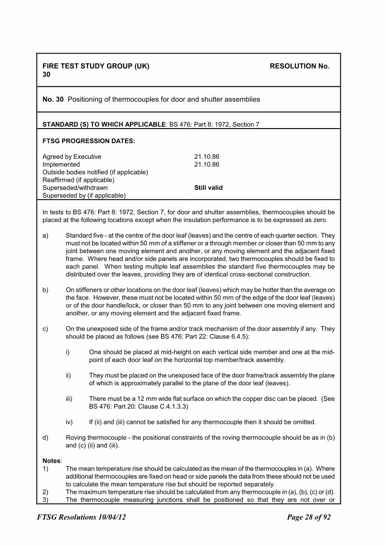
No. 30 Positioning of thermocouples for door and shutter assemblies
STANDARD (S) TO WHICH APPLICABLE: BS 476: Part 8: 1972, Section 7
FTSG PROGRESSION DATES:
Agreed by Executive
Implemented
Outside bodies notified (if applicable)
Reaffirmed (if applicable)
Superseded/withdrawn
Superseded by (if applicable)
21.10.86
21.10.86
Still valid
In tests to BS 476: Part 8: 1972, Section 7, for door and shutter assemblies, thermocouples should be
placed at the following locations except when the insulation performance is to be expressed as zero.
a) Standard five - at the centre of the door leaf (leaves) and the centre of each quarter section. They
must not be located within 50 mm of a stiffener or a through member or closer than 50 mm to any
joint between one moving element and another, or any moving element and the adjacent fixed
frame. Where head and/or side panels are incorporated, two thermocouples should be fixed to
each panel. When testing multiple leaf assemblies the standard five thermocouples may be
distributed over the leaves, providing they are of identical cross-sectional construction.
b) On stiffeners or other locations on the door leaf (leaves) which may be hotter than the average on
the face. However, these must not be located within 50 mm of the edge of the door leaf (leaves)
or of the door handle/lock, or closer than 50 mm to any joint between one moving element and
another, or any moving element and the adjacent fixed frame.
c) On the unexposed side of the frame and/or track mechanism of the door assembly if any. They
should be placed as follows (see BS 476: Part 22: Clause 6.4.5):
i) One should be placed at mid-height on each vertical side member and one at the mid-
point of each door leaf on the horizontal top member/track assembly.
ii) They must be placed on the unexposed face of the door frame/track assembly the plane
of which is approximately parallel to the plane of the door leaf (leaves).
iii) There must be a 12 mm wide flat surface on which the copper disc can be placed. (See
BS 476: Part 20: Clause C.4.1.3.3)
iv) If (ii) and (iii) cannot be satisfied for any thermocouple then it should be omitted.
d) Roving thermocouple - the positional constraints of the roving thermocouple should be as in (b)
and (c) (ii) and (iii).
Notes:
1) The mean temperature rise should be calculated as the mean of the thermocouples in (a). Where
additional thermocouples are fixed on head or side panels the data from these should not be used
to calculate the mean temperature rise but should be reported separately.
2) The maximum temperature rise should be calculated from any thermocouple in (a), (b), (c) or (d).
3) The thermocouple measuring junctions shall be positioned so that they are not over or
FTSG Resolutions 10/04/12 Page 29 of 92
FIRE TEST STUDY GROUP (UK) RESOLUTION No.
30
immediately adjacent to any feature that constitutes a potential failure with respect to integrity
rather than insulation, ie where the measuring junction may be heated by the passage of hot
gases from the furnace through the specimen. (See BS 476: Part 20: Clause C.4.1.3.4)
4) Thermocouples may be placed on a door assembly with no insulation, or incorporating glazing
with zero insulation, but the data from these can be used for assessments or information only.
5) When testing two separate door assemblies simultaneously the above requirements refer to each
door assembly.
FTSG Resolutions 10/04/12 Page 30 of 92
FIRE TEST STUDY GROUP (UK) RESOLUTION No
31
No. 31 Pressure conditions when testing non-separating elements
STANDARD (S) TO WHICH APPLICABLE: BS 476: Part 8: 1972, Sections 4 and 5
FTSG PROGRESSION DATES:
Agreed by Executive
Implemented
Outside bodies notified (if applicable)
Reaffirmed (if applicable)
Superseded/withdrawn
Superseded by (if applicable)
June 1986
June 1986
Still valid
When testing non-separating elements (beams and columns) to BS 476: Part 8: 1972, Sections 4 and 5,
the following positive pressure conditions will apply after the first 5 minutes of test.
a) Beams
The pressure inside the furnace is to be controlled so that the mean static pressure, relative to the
laboratory, 100 mm below the soffit of the concrete cover slab is maintained at 18 Pa ± 2 Pa.
b) Columns
The pressure inside the furnace is to be controlled so that the mean static pressure at the top of
the column is maintained at 9 Pa ± 2 Pa.
Note:
The pressure value for columns complies with the proposed requirements in BS 476: Part 20: Clause 3.2.3
where the position of the neutral axis is allowed to be 2000 mm up from the base of the column.
Assuming a pressure gradient of 9 Pa/m and a total exposed height of 3000 mm the pressure value at the
top of the column will be 9 Pa.
FTSG Resolutions 10/04/12 Page 31 of 92
FIRE TEST STUDY GROUP (UK) RESOLUTION No. 32
No. 32 Loading advise for clients conducting loaded steel section fire resistance tests
STANDARD (S) TO WHICH APPLICABLE: BS 476: Part 8: 1972
FTSG PROGRESSION DATES:
Agreed by Executive
Implemented
Outside bodies notified (if applicable)
Reaffirmed (if applicable)
Superseded/withdrawn
Superseded by (if applicable)
June 1986
June 1986
Still valid
a) When performing tests on structural steel elements to BS 476: Part 8: 1972, where the loading
conditions are not specified, sponsors should be advised to have the elements loaded to their
maximum permissible stresses in accordance with British Standard 449: Part 2.
b) Test reports on structural steelwork should include the following information:
i) Test load.
ii) The maximum load which could be applied to a specimen when designed in accordance
with BS 449: Part 2.
iii) The load capacity (or moment capacity) of the specimen at 20C when designed in
accordance with BS 5950: Part 1 and the ratio of test load : load capacity at 20C.
See Appendix I for a typical calculation.
APPENDIX I
SAMPLE CALCULATIONS TO BE INCLUDED IN REPORTS ON 305 MM X 127 MM X 42 KG/M
BEAMS
The imposed load to be applied to the beam was calculated to give a test load which would induce the
maximum permissible stress stated by BS 449: Part 2: 1969, assuming there to be no composite action
between the concrete slab and steel beam. The beam was simply supported and loaded using a four-
point loading system.
Data :
Universal beam section 305 mm x 127 mm x 42 kg/m (calcs on basis of actual section size)
Clear span between supports (L) = 4.25 m
Elastic modulus (Z) = 530 cm³
Allowable stress (fbc) = 165 N/mm²
FTSG Resolutions 10/04/12 Page 32 of 92
FIRE TEST STUDY GROUP (UK) RESOLUTION No. 32
(From Table 2, BS 449: Part 2: 19694, page 28)
Test Load :
Maximum permissible bending moment M = fbcz
= 165 x 10³ x 530 x 10-6
kNm
Dead Load :
Mass of beam = 42 kg/m
Weight of beam = 42 x 9.81 x 10-3
= 0.412 kN/m³
Size of concrete slab = 920 mm wide x 130 mm deep
Density of concrete = 2210 kg/m³
Weight of concrete = 0.920 x 0.130 x 2210 x 9.81 x 10-3
kN/m
= 2.593 kN/m
Total dead load (w) = 2.593 + 0.412
= 3.005 kN/m
Moment at centre of span due to UDL = wL²
8
= 3.005 x 4.25²
8
= 6.785 kNm
Imposed Load :
Imposed load required to induce bending moment at centre of span of :
87.45 kNm = 87.45 - 6.78 = 80.67 kNm
Moment at centre induced by total imposed load of PkN
= P x 2.125 - P (1.5 + 0.5)
2 4
= 0.5625P kNm
0.5625P = 80.67 kNm
Total imposed load P = 80.67
0.5625
= 143.4 Kn
FTSG Resolutions 10/04/12 Page 33 of 92
FIRE TEST STUDY GROUP (UK) RESOLUTION No. 32
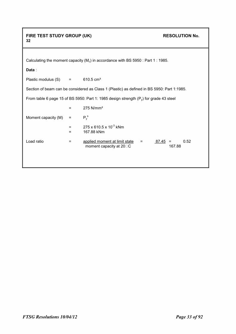
Calculating the moment capacity (Mc) in accordance with BS 5950 : Part 1 : 1985.
Data :
Plastic modulus (S) = 610.5 cm³
Section of beam can be considered as Class 1 (Plastic) as defined in BS 5950: Part 1:1985.
From table 6 page 15 of BS 5950: Part 1: 1985 design strength (Py) for grade 43 steel
= 275 N/mm²
Moment capacity (M) = Pys
= 275 x 610.5 x 10-3
kNm
= 167.88 kNm
Load ratio = applied moment at limit state = 87.45 = 0.52
moment capacity at 20C 167.88
FTSG Resolutions 10/04/12 Page 34 of 92
FIRE TEST STUDY GROUP (UK) RESOLUTION No.
33
No. 33 Moisture Content
STANDARD (S) TO WHICH APPLICABLE: BS 476: Part 8: 1972
FTSG PROGRESSION DATES:
Agreed by Executive
Implemented
Outside bodies notified (if applicable)
Reaffirmed (if applicable)
Superseded/withdrawn
Superseded by (if applicable)
22.1.87
22.1.87
Still valid
When testing to BS 476: Part 8: 1972 FTSG (UK) will use accepted values for, or will accept advice from
knowledgeable bodies for, equilibrium moisture contents for various materials, the minimum likely time to
achieve that condition, and the appropriate procedures for their determination.
A laboratory will take every reasonable precaution to ensure that tests are not conducted on any
construction or product which may include materials that are at an atypical moisture content. It shall
inform clients of the possible limited acceptability of a result which is achieved in a test where either the
precise moisture content is not known, or has not been measured, or where moisture equilibrium has not
been achieved, and a statement to this effect shall be included in the test report.
A laboratory will quote where practicable in all fire resistance test reports, the measured moisture content
of all hygroscopic materials included within a test specimen, together with a statement on the method by
which it was determined, and where appropriate the calculation used in obtaining the stated value.
Quoted values of moisture content shall, wherever possible, be determined by oven drying techniques.
The following methods may be used to monitor moisture content to establish when equilibrium had been
reached. Method a) may also be used where oven drying techniques are not practicable.
a) By proven meter techniques eg Protimeter.
b) By removing off-cuts or core samples from the specimen.
c) By conditioning geometrically representative samples with the specimen.
d) By conditioning a sample tray of material kept with the specimen.
Note:
Monitored values are not necessarily definite moisture contents whereas measured values are.
Timber
When monitoring a composite specimen, such as a door, with an electrode type meter, insulated shaft
electrodes should be used to avoid erroneous readings caused be facing materials and gluelines
Concrete and Masonry
FTSG Resolutions 10/04/12 Page 35 of 92
FIRE TEST STUDY GROUP (UK) RESOLUTION No.
33
Different thicknesses within a specimen may require separate assessments of moisture content. Special
attention is required where non-uniformity of moisture distribution may be experienced eg metal decks.
Applied Coatings
Eg sprayed insulation materials, intumescent coatings. These shall be monitored by use of a sample tray
of material taking into account that, in general, areas of greater thickness will require longer drying
periods.
FTSG Resolutions 10/04/12 Page 36 of 92
FIRE TEST STUDY GROUP (UK) RESOLUTION No
34
No. 34 Positioning of furnace thermocouples
STANDARD (S) TO WHICH APPLICABLE: BS 476: Part 8: 1972
FTSG PROGRESSION DATES:
Agreed by Executive
Implemented
Outside bodies notified (if applicable)
Reaffirmed (if applicable)
Superseded/withdrawn
Superseded by (if applicable)
22.1.87
22.1.87
Still valid
When testing to BS 476: Part 8: 1972 the 100 mm dimension referred to in clause 1.4.3 shall be between
the thermocouple hot junction and the nearest point on the specimen in any direction. For doors in walls
the dimension shall be from the nearest position on either the door or the wall, whichever is appropriate to
the predetermined position of the thermocouple within the furnace.
FTSG Resolutions 10/04/12 Page 37 of 92
FIRE TEST STUDY GROUP (UK) RESOLUTION No
35
No. 35 Use of cotton pad and intepretation of integrity failure.
STANDARD (S) TO WHICH APPLICABLE: BS 476: Part 8: 1972
FTSG PROGRESSION DATES:
Agreed by Executive
Implemented
Outside bodies notified (if applicable)
Reaffirmed (if applicable)
Superseded/withdrawn
Superseded by (if applicable)
22.1.87
22.1.87
Still valid
When testing to BS 476: Part 8: 1972 loss of integrity of any separating construction shall be judged on the
basis of the cotton wool pad test, the pad being applied for a duration of 10-15 seconds and at a distance
of 20-30 mm from the aperture. Only when the level of radiation from the surface of the specimen
prohibits use of the cotton wool pad may other criteria be applied, eg specified in 7.4 and 8.4 of the
Standard.
The dimensions of cracks or fissures referred to in clause 8.4 of BS 476: Part 8: 1972 shall be interpreted
such that the gap is greater than 150 mm in one dimension and 6 mm in the other for an integrity failure to
be deemed to have occurred. The 150 mm dimension shall be taken as the developed length of the
crack, irrespective of shape.
FTSG Resolutions 10/04/12 Page 38 of 92
FIRE TEST STUDY GROUP (UK) RESOLUTION No
36
No. 36 Suspended ceiling test configuration.
STANDARD (S) TO WHICH APPLICABLE: BS 476: Part 8: 1972, Section 6
FTSG PROGRESSION DATES:
Agreed by Executive
Implemented
Outside bodies notified (if applicable)
Reaffirmed (if applicable)
Superseded/withdrawn
Superseded by (if applicable)
22.1.87
22.1.87
Still valid
When testing suspended ceilings to BS 476: Part 8: 1972, Section 6, the ends of all members in the metal
suspension system shall be cut square and shall abut tightly against the perimeter framework such that all
expansion of the members shall be accommodated within the specimen and not at the perimeter.
Test reports shall include a diagram which indicates the number and the location of all expansion devices,
support positions, joints between members, etc. The report shall contain a comment in the conclusion
regarding the operation or otherwise of expansion devices.
FTSG Resolutions 10/04/12 Page 39 of 92
FIRE TEST STUDY GROUP (UK) RESOLUTION No
37
No. 37 Test configuration for beams with three-sided exposure.
STANDARD (S) TO WHICH APPLICABLE: BS 476: Part 8: 1972, Section 6
FTSG PROGRESSION DATES:
Agreed by Executive
Implemented
Outside bodies notified (if applicable)
Reaffirmed (if applicable)
Superseded/withdrawn
Superseded by (if applicable)
22.1.87
22.1.87
Still valid
When testing suspended ceilings to BS 476: Part 8: 1972, Section 6, three-sided exposure only of the
steel beams shall be ensured by the use of strips of mineral fibre insulating material, the width of the top
flange, placed on the upper flange and running the length of each beam, prior to the application of the
cover slabs. The mineral fibre insulating material shall be of 12-25 mm nominal thickness, and of suitable
density to allow compression under the cover slabs.
Explanatory Note:
No specific density is quoted for the mineral fibre insulating material, since the relationship between
density and compressibility varies from one fibre type to another. The density chosen should be such as
to ensure that the spaces between the tops of the beams and the cover slabs are completely filled.
.
FTSG Resolutions 10/04/12 Page 40 of 92
FIRE TEST STUDY GROUP (UK) RESOLUTION No
38
No. 38 Loaded beam section
STANDARD (S) TO WHICH APPLICABLE: BS 476: Part 8: 1972
FTSG PROGRESSION DATES:
Agreed by Executive
Implemented
Outside bodies notified (if applicable)
Reaffirmed (if applicable)
Superseded/withdrawn
Superseded by (if applicable)
22.1.87
22.1.87
Still valid
When testing to BS 476: Part 8: 1972, in the absence of a specific request from the sponsor, a beam
(tests to section 5) shall be 305 mm by 127 mm by 42 kg/m on a nominal 4000 mm span, and a column
(tests to section 4) shall be 203 mm by 203 mm by 52 kg/m.
.
FTSG Resolutions 10/04/12 Page 41 of 92
FIRE TEST STUDY GROUP (UK) RESOLUTION No
39
No. 39 Test specimen requirements for valid testing.
STANDARD (S) TO WHICH APPLICABLE: BS 476: Part 7: 1971
FTSG PROGRESSION DATES:
Agreed by Executive
Implemented
Outside bodies notified (if applicable)
Reaffirmed (if applicable)
Superseded/withdrawn
Superseded by (if applicable)
22.1.87
22.1.87
Still valid
Materials tested to BS 476: Part 7: 1971 shall be deemed unclassifiable if the material does not
remain in position long enough to allow the pilot flame to contact the material throughout the full
period of its ignition. If the material ignites during the first minute of the test, however, and then
shrinks away from the pilot flame whilst continuing to burn for at least five seconds after extinction
of the pilot flame then the test result on that specimen shall be deemed valid, provided that the
material does not shrink or melt in advance of the flame front.
FTSG Resolutions 10/04/12 Page 42 of 92
FIRE TEST STUDY GROUP (UK) RESOLUTION No
40
No. 40 Limitation on application of deflection criteria
STANDARD (S) TO WHICH APPLICABLE: BS 476: Part 8: 1972
FTSG PROGRESSION DATES:
Agreed by Executive
Implemented
Outside bodies notified (if applicable)
Reaffirmed (if applicable)
Superseded/withdrawn
Superseded by (if applicable)
22.1.87
22.1.87
Still valid
When testing loadbearing elements to BS 476: Part 8: 1972, the deflection criteria shall apply only
during the heating period and at the initial applied load condition. They shall not be applied to
determine failure in the re-load test.
FTSG Resolutions 10/04/12 Page 43 of 92
FIRE TEST STUDY GROUP (UK) RESOLUTION No
41
No. 41 Threshold detail for doors without a threshold detail.
STANDARD (S) TO WHICH APPLICABLE: BS 476: Part 8: 1972, Section 7
FTSG PROGRESSION DATES:
Agreed by Executive
Implemented
Outside bodies notified (if applicable)
Reaffirmed (if applicable)
Superseded/withdrawn
Superseded by (if applicable)
22.1.87
22.1.87
Superseded 27-1-88
Resolution 48 then by Resolution No 51
When testing to BS 476: Part 8: 1972, Section 7, where a threshold detail is not included in the design of
he doorset, a standard threshold shall be fitted as follows:
A non-combustible threshold, or combustible threshold faced with non-combustible material of minimum
thickness 6 mm.
The standard threshold is to extend a minimum 250 mm from the face of the door leaf/leaves on both the
exposed and unexposed sides. The width of the threshold to be equal to that of the overall width of the
doorset plus 200 mm.
Where the threshold is included in the design of the doorset this should be positioned in such a way as to
be representative of practice eg flush with or on top of the standard threshold.
FTSG Resolutions 10/04/12 Page 44 of 92
FIRE TEST STUDY GROUP (UK) RESOLUTION No
42
No. 42 Design of the roving thermocouple.
STANDARD (S) TO WHICH APPLICABLE: BS 476: Part 8: 1972
FTSG PROGRESSION DATES:
Agreed by Executive
Implemented
Outside bodies notified (if applicable)
Reaffirmed (if applicable)
Superseded/withdrawn
Superseded by (if applicable)
22.1.87
22.1.87
Still valid
When conducting tests to BS 476: Part 8: 1972, a portable thermometer is used to measure the
temperature at a point on the unexposed face of a separating element (to determine compliance with the
'insulation' criterion given in 1.5.3 of the Standard) then the design of the thermocouple shall be as follows:
The thermocouple shall be manufactured from Type T or Type K wires (conforming to BS 4937: Part 4 or
Part 5) with a nominal diameter of 1 mm. The hot junction shall be formed by brazing the wires to a
12 mm diameter copper disc of 0.5 mm thickness. The wires shall be bent substantially normal to the
disc, to enable their insertion into the holes of a twin bore insulator. The insulator shall have a diameter of
8 mm with holes of 2 mm diameter, and may be supported in a suitable steel tube with a wall thickness of
2-3 mm, such that 3 mm of the insulator is allowed to protrude. The back of the copper disc shall be
3 mm from the end of the insulator, and 6 mm from the end of the steel support tube, if used.
Notes:
1. All dimensions given are nominal.
2. A diagram of the above described arrangement can be found in EEC report EUR 8750, Part II,
Chapter 1, Section III, Figure 3.
3. The design of the portable thermocouple described is a development from the 'fixed'
thermocouple design specified in 1.4.5 of the Standard. The asbestos pad has however been
abandoned since its effect was to reduce the rate of response of the thermocouple. This effect
was significant when applying a 'cold thermocouple' to a surface rapidly increasing in temperature
near the point of insulation failure. The use of 1 mm diameter wires has been adopted since
0.5 mm diameter wires were found to be insufficiently robust for this application. The use of
thicker wires has not been found to significantly affect response time as compared to the use of
thinner wires.
FTSG Resolutions 10/04/12 Page 45 of 92
FIRE TEST STUDY GROUP (UK) RESOLUTION No
43
No. 43 Statement in report regarding use of FTSG Resolutions.
STANDARD (S) TO WHICH APPLICABLE: BS 476 : Part 8 : 1972 and BS 476 : Parts 21-24 : 1987
FTSG PROGRESSION DATES:
Agreed by Executive
Implemented
Outside bodies notified (if applicable)
Reaffirmed (if applicable)
Superseded/withdrawn
Superseded by (if applicable)
04.06.87
11.06.87
FSM/1/6 18.04.88
discussed by committee : 10.05.88
Doc 88/37262 page 5 (See Note 1 below)
Still valid
REASON :
There is a need to state in the report that FTSG Resolutions have been implemented in conducting
the test.
RESOLUTION :
A statement shall be made in all relevant test reports regarding the adoption, or otherwise, of FTSG
Resolutions. Either of the following statements shall be used as appropriate.
i) "Where areas of the test specification are ambiguous or open to interpretation the Fire Test
Study Group Resolutions have been followed (where appropriate [except as stated below]).
These Resolutions provide the basis of common agreements between the fire test
laboratories which are members of this Group."
ii) "The procedure(s) adopted for __________________ during the test was/were different
from that given in Resolution(s) No(s). _______ of the Fire Test Study Group. The different
interpretation of ______________________________ requirements was adopted at the
request of the sponsor."
Note 1:
FSM/1/6 considered that the Resolution was not relevant to BSI and on that basis did not accept its
contents.
FTSG Resolutions 10/04/12 Page 46 of 92
FIRE TEST STUDY GROUP (UK) RESOLUTION No
44
No. 44 Classification of fire resistance durations.
STANDARD (S) TO WHICH APPLICABLE: BS 476 : Part 20 : 1987
FTSG PROGRESSION DATES:
Agreed by Executive
Implemented
Outside bodies notified (if applicable)
Reaffirmed (if applicable)
Superseded/withdrawn
Superseded by (if applicable)
07.12.87
14.12.87
FSM/1/6 18.04.88
discussed by committee : 10.05.88
BSI minute reference : doc 88/37262
Subsequently accepted by FSM/1/6 16.05.89,
minute reference 89/39160 and included in draft
amendment doc 89/43833.
Withdrawn 10.5.88
REASON :
Standard is ambiguous on rounding of part minutes.
RESOLUTION :
When testing to BS 476: Part 20: 1987 the test results shall be stated in terms of completed, whole,
elapsed minutes.
eg failure occurring at 29 minutes 45 second shall be expressed as a fire resistance of 29 minutes.
Note:
This revision is in line with the requirements of EEC Technical Report EUR 8750 (1984) and the
revisions to ISO 834 document N292.
FTSG Resolutions 10/04/12 Page 47 of 92
FIRE TEST STUDY GROUP (UK) RESOLUTION No 45
No. 45 Loading
STANDARD (S) TO WHICH APPLICABLE: BS 476 : Part 20 : 1987
FTSG PROGRESSION DATES:
Agreed by Executive
Implemented
Outside bodies notified (if applicable)
Reaffirmed (if applicable)
Superseded/withdrawn
Superseded by (if applicable)
20.01.88
27.01.88
FSM/1/6 submitted to BSI : 18.04.88
discussed by committee : 10.05.88
BSI minute reference : doc 88/37262
Draft Amendment : 89/43833
amendments/revision : 10.05.88
Withdrawn 30.04.90
REASON :
There is ambiguity in the Standard regarding what constitutes "constant load".
RESOLUTION :
When testing to BS 476: Part 20: 1987 the requirement to maintain a constant load (Clause 6.2.3)
is taken to mean "constant" within the "specified tolerance" (as given in Clause 9.1.2), ie within
±2%.
Note:
This resolution allows periodic load adjustment to be made to compensate for the effects of
deformation of a specimen. A more sophisticated loading system with a "built-in" self
compensating facility is not, therefore necessary.
FTSG Resolutions 10/04/12 Page 48 of 92
FIRE TEST STUDY GROUP (UK) RESOLUTION No
46
No. 46 Applicability of Results
STANDARD (S) TO WHICH APPLICABLE: BS 476 : Parts 21-24 : 1987
FTSG PROGRESSION DATES:
Agreed by Executive
Implemented
Outside bodies notified (if applicable)
Reaffirmed (if applicable)
Superseded/withdrawn
Superseded by (if applicable)
20.01.88
27.01.88
FSM/1/6 Feb 1988
BSI minute reference : 88/37262
Rejected BSI : 10.05.88
Withdrawn 17.05.89
Resolution 50
REASON :
There is not adequate provision in the Standards to indicate limitations or qualifications on the test
results.
RESOLUTION :
When reporting tests to BS 476: Parts 21-24: 1987 the conclusion or that section of the report,
however titled, which details the test results, shall be followed immediately by a section entitled
"Applicability". This section shall contain the mandatory statement required by clause 12 (0) of BS
476: Part 20: 1987. It shall also contain any other statements required by the other various parts of
the Standard and any other limitations or qualifications on the test results, eg regarding the
pressure conditions.
FTSG Resolutions 10/04/12 Page 49 of 92
FIRE TEST STUDY GROUP (UK) RESOLUTION No
47
No. 47 Deflection Criteria
STANDARD (S) TO WHICH APPLICABLE: BS 476 : Part 21 : 1987
FTSG PROGRESSION DATES:
Agreed by Executive
Implemented
Outside bodies notified (if applicable)
Reaffirmed (if applicable)
Superseded/withdrawn
Superseded by (if applicable)
20.01.88
27.01.88
FSM/1/6 18.04.88
BSI minute reference : doc 88/37262
amended 10.05.88
Still valid
REASON :
Clarification is required as to when deflection criteria shall apply.
RESOLUTION :
When testing loadbearing elements to BS 476: Part 21: 1987, the deflection criteria shall apply only
during the heating period and at the initial applied load condition. They shall not be applied to
determine failure in any test for residual loadbearing capacity where appropriate.
Note:
This revision is in line with the requirements of EEC Technical Report EUR 8750 (1984).
FTSG Resolutions 10/04/12 Page 50 of 92
FIRE TEST STUDY GROUP (UK) RESOLUTION No
48
No. 48 Door Threshold Details
STANDARD (S) TO WHICH APPLICABLE: BS 476 : Part 22 : 1987
FTSG PROGRESSION DATES:
Agreed by Executive
Implemented
Outside bodies notified (if applicable)
Reaffirmed (if applicable)
Superseded/withdrawn
Superseded by (if applicable)
20.01.88
27.01.88
FSM/1/6 Feb 1989
Rejected BSI Feb 1988
BSI minute reference : 88/37262
Withdrawn 30.09.88
Resolution 51
REASON :
By specifying a threshold detail for doorsets a more realistic situation can be simulated.
RESOLUTION :
When testing to BS 476: Part 22: 1987, where a threshold detail is not included in the design of the
doorset, a standard threshold shall be fitted as follows:
A non-combustible threshold, or combustible threshold faced with non-combustible material of
minimum thickness 6 mm.
The standard threshold is to extend a minimum 250 mm from the face of the door leaf/leaves on
both the exposed and unexposed sides. The width of the threshold to be equal to that of the overall
width of the doorset plus 200 mm.
Where the threshold is included in the design of the doorset this should be positioned in such a way as
to be representative of practice, eg flush with or on top of the standard threshold.
FTSG Resolutions 10/04/12 Page 51 of 92
FIRE TEST STUDY GROUP (UK) RESOLUTION No
50
No. 50 Limitations on use of results
STANDARD (S) TO WHICH APPLICABLE: BS 476 : Parts 21-24 : 1987
FTSG PROGRESSION DATES:
Agreed by Executive
Implemented
Outside bodies notified (if applicable)
Reaffirmed (if applicable)
Superseded/withdrawn
Superseded by (if applicable)
29.09.88
17.05.89
FSM/1/6 08.11.88
Document No. :88/45018
BSI minute reference : 89/39160
Still valid
REASON :
There is no adequate provision in the Standards to indicate limitations or qualifications on the test
results.
RESOLUTION :
When reporting tests to BS 476: Parts 21-24: 1987 the conclusion or that section of the report,
however titled, which details the test results, shall be followed immediately by a section entitled
'Limitations'. This section shall contain the mandatory statement required by clause 12 (0) of BS
476: Part 20: 1987. It shall also contain any other statements required by the other various parts of
the Standard and any other limitations or qualifications on the test results, eg regarding the
pressure conditions.
FTSG Resolutions 10/04/12 Page 52 of 92
FIRE TEST STUDY GROUP (UK) RESOLUTION No
51
No. 51 Door Threshold Details
STANDARD (S) TO WHICH APPLICABLE: BS 476 : Part 22 : 1987
FTSG PROGRESSION DATES:
Agreed by Executive
Implemented
Outside bodies notified (if applicable)
Reaffirmed (if applicable)
Superseded/withdrawn
Superseded by (if applicable)
29.09.88
30.09.88
FSM/1/6 08.11.88
BSI Document No. : 88/45018
BSI minute reference : 89/39160
Still valid
REASON :
The present, unspecified, threshold details for doorsets are unsatisfactory for two reasons:
1. A non-continuous threshold creates unnatural conditions in terms of air movement
underneath the door which can prejudice the fire resistance performance. The simple
expedient of providing a wider, flat threshold removes the doubt.
2. Several door and shutter constructions deform badly along the unsupported lower edge. In
practice a continuous floor level in the vicinity of this edge maintains a relatively small gap
compared to the large gap created when a door is tested and distorts beyond the current
unspecified threshold which is typically equal to the thickness of the supporting
construction.
RESOLUTION :
When testing to BS 476: Part 22: 1987, where a threshold detail is not included in the design of the
doorset, a standard threshold shall be fitted as follows:
A non-combustible threshold, or combustible threshold faced with non-combustible material of
minimum thickness 6 mm.
The standard threshold is to extend a minimum 250 mm from the face of the door leaf/leaves on
both the exposed and unexposed sides. The width of the threshold to be equal to that of the
overall width of the doorset plus 200 mm.
Where the threshold is included in the design of the doorset this should be positioned in such a
way as to be representative of practice, eg flush with or on top of the standard threshold.
Note: This detailing is in line with draft EUR 8750: Chapter 2: Section VI.
FTSG Resolutions 10/04/12 Page 53 of 92
FIRE TEST STUDY GROUP (UK) RESOLUTION No
53
No. 53 Testing to BS 476:Part8:1972 Versus BS 476:Parts 20-23:1987.
STANDARD (S) TO WHICH APPLICABLE: BS 476 : Part 20-23: 1987, BS 476:Part 8:1972
FTSG PROGRESSION DATES:
Agreed by Executive
Implemented
Outside bodies notified (if applicable)
Reaffirmed (if applicable)
Superseded/withdrawn
Superseded by (if applicable)
29.09.88
17.05.89
FSM/1/6 08.11.88
BSI Document No.: 88/45018:
BSI minute reference : 89/39160
Still valid
REASON :
BS 476:Part 8:1972 has been withdrawn and replaced by the more comprehensive and technically
superior Part 20 series.
It therefore seems logical that all fire resistance tests carried out in the future for UK regulatory
purposes should be conducted in accordance with the current standard.
RESOLUTION :
Members of the Fire Test Study Group (UK) agree to conduct all fire resistance tests for UK regulatory
purposes in accordance with the appropriate part of the BS 476:Part 20 Series and to desist
henceforth from conducting tests in accordance with BS 476:Part 8:1972.
It is appreciated that other countries regulatory requirements may still require test evidence in
accordance with BS 476:Part 8:1972 and that occasionally, for example is cases of litigation, it may be
necessary to conduct tests to the withdrawn standard. In these cases only will members undertake
tests in accordance with BS 476:Part 8:1972.
FTSG Resolutions 10/04/12 Page 54 of 92
FIRE TEST STUDY GROUP (UK) RESOLUTION No
55
No. 55 Minimum Number of Loading Points for Horizontal Separating Elements.
STANDARD (S) TO WHICH APPLICABLE: BS 476 : Part 20 : 1987
FTSG PROGRESSION DATES:
Agreed by Executive
Implemented
Outside bodies notified (if applicable)
Reaffirmed (if applicable)
Superseded/withdrawn
Superseded by (if applicable)
29.09.88
17.06.89
FSM/1/6 08.11.88
BSI Document No.: 88/45018:
BSI minute reference : 89/39160
Draft Amendment : 89/43833
WITHDRAWN 30.04.90
REASON :
Current requirement is for minimum 24 loading points on a 4 m by 3 m specimen. This compares
with EUR 8750 where minimum number would be 12 and current ISO 834 proposal where
minimum number is 10. (Subject discussed in FSM/1/6. Document 88/35722 refers.)
RESOLUTION :
Amendment to Clause 6.2.3
Delete second paragraph.
Insert : 'The load shall be applied uniformly over the surface such that at any single point the load
does not exceed 10% of the total load.'
FTSG Resolutions 10/04/12 Page 55 of 92
FIRE TEST STUDY GROUP (UK) RESOLUTION No
56
No. 56 Revision of 6.4.2.5 and C.2.2.4 Relating to Frequency of Measurement
STANDARD (S) TO WHICH APPLICABLE: BS 476 : Part 20 : 1987
FTSG PROGRESSION DATES:
Agreed by Executive
Implemented
Outside bodies notified (if applicable)
Reaffirmed (if applicable)
Superseded/withdrawn
Superseded by (if applicable)
17.06.88
29.09.88
FSM/1/6 08.11.88
BSI Document No. : 88/45018
BSI minute reference : 89/39160
Draft Amendment : 89/43833
WITHDRAWN 30.04.90
REASON :
Failure criteria and calculation of area under heating curve are all based on values measured at
intervals of one minute or periods of whole minutes. The two subject sections of BS 476: Part 20:
1987 refer to measurements made at intervals of less than one minute which in unnecessary.
RESOLUTION :
Amendment to Clauses
6.4.2.5 (a) Delete second paragraph
(b) Third paragraph, second sentence. Insert the words 'displayed and' before
and word 'logged'.
C.2.2.4 Penultimate sentence. Delete '30s' and insert '60s'.
FTSG Resolutions 10/04/12 Page 56 of 92
FIRE TEST STUDY GROUP (UK) RESOLUTION No
57
No. 57 Revision of 6.1.8 Relating to Time of Commencement of Heating Period
STANDARD (S) TO WHICH APPLICABLE: BS 476 : Part 20 : 1987
FTSG PROGRESSION DATES:
Agreed by Executive
Implemented
Outside bodies notified (if applicable)
Reaffirmed (if applicable)
Superseded/withdrawn
Superseded by (if applicable)
29.09.88
17.06.89
FSM/1/6 08.11.88
BSI Document No. 88/45018
BSI minute reference 89/39160
Withdrawn 24.02.90
Resolution 66
REASON :
The meaning of the second paragraph of 6.1.8 is not clear in the absence of a precise definition of
the word 'axis'. If, however, the paragraph is taken to mean that the thermocouple used to define
time of commencement of test is to be placed near to the centre of gravity of the element under
test, then (with the exception of columns) no furnace control thermocouple would normally be
located in this area.
Since all UK laboratories now have fairly sophisticated equipment for control and measurement, it is
possible to scan the output of a number of thermocouples continuously and it is considered to be
desirable and a relatively simple matter to start timing a test automatically when any one of the
furnace control thermocouples reaches 40C.
RESOLUTION :
The time of commencement of the heating period shall be determined from the outputs of the
thermocouples used for furnace temperature control all such thermocouples shall be continuously
monitored, and timing started when a temperature of 40C is reached by any one of them.
The timing device shall comply with the requirements given in C.2.3.
Note: Adoption of this revision would necessitate the following additional modifications to the
Standard:
(a) C.7.1 Delete in its entirety.
(b) C.9 First sentence. Delete 'the timing control thermocouple' and insert 'one of the
furnace control thermocouples'.
FTSG Resolutions 10/04/12 Page 57 of 92
FIRE TEST STUDY GROUP (UK) RESOLUTION No
58
No. 58 Use of the Cotton Pad
STANDARD (S) TO WHICH APPLICABLE: BS 476 : Parts 20-23 : 1987
FTSG PROGRESSION DATES:
Agreed by Executive
Implemented
Outside bodies notified (if applicable)
Reaffirmed (if applicable)
Superseded/withdrawn
Superseded by (if applicable)
29.09.88
18.05.89
FSM/1/6 08.11.88
BSI Document No. 88/45018
BSI minute reference : 89/39160
Draft Amendment : 89/43833
WITHDRAWN 30.04.90
REASON :
There is inconsistency in Clause C.10.3.2 of BS 476: Part 20: 1987.
RESOLUTION :
Amendment to Clause C.10.3.2.
Replace paragraph 8 by:
'The use of the cotton pad shall be discontinued when the unexposed face of the construction
indicates a temperature of 300C in the vicinity of the gap being evaluated. This temperature
shall be measured by placing the centre of the roving thermocouple, specified in 6.4.2.2, at a
distance of between 30 mm and 70 mm to the side of, or below the gap, or by the nearest
unexposed face fixed thermocouple if one is positioned within 30 mm to 70 mm of the gap.
FTSG Resolutions 10/04/12 Page 58 of 92
FIRE TEST STUDY GROUP (UK) RESOLUTION No
59
No. 59 Reduced Size Furnaces
STANDARD (S) TO WHICH APPLICABLE: BS 476 : Part 20 : 1987
FTSG PROGRESSION DATES:
Agreed by Executive
Implemented
Outside bodies notified (if applicable)
Reaffirmed (if applicable)
Superseded/withdrawn
Superseded by (if applicable)
29.09.88
18.05.89
FSM/1/6 08.11.88
BSI Document No. 88/45018
BSI minute reference : 89/39160
Draft Amendment : 89/43833
WITHDRAWN 30.04.90
REASON :
In Clause 6.1.2 of BS 476: Part 20: 1987 it is not clear what size of furnace will constitute a reduced
size furnace.
RESOLUTION :
The limitation on the specimen/furnace ratio of 1.5 : 1 referred to in Clause 6.1.2 of BS 476: Part
20: 1987 is only applicable to furnaces having a chamber size not greater than 1.5 m by 1.5 m.
FTSG Resolutions 10/04/12 Page 59 of 92
FIRE TEST STUDY GROUP (UK) RESOLUTION No
60
No. 60 Loading on Stud Walls (Discrete Loadbearing Members)
STANDARD (S) TO WHICH APPLICABLE: BS 476 : Part 21 : 1987
FTSG PROGRESSION DATES:
Agreed by Executive
Implemented
Outside bodies notified (if applicable)
Reaffirmed (if applicable)
Superseded/withdrawn
Superseded by (if applicable)
29.09.88
08.12.88
FSM/1/6 08.11.88
BSI Document No. 88/45018
BSI minute reference 89/39160
Still valid
REASON :
There is a need to ensure that laboratories spread the load on stud walls in a consistent manner.
RESOLUTION :
Unless the design or intended application require that each stud is loaded separately, a timber
spreader beam having a cross section 100 mm by 50 mm, suitably protected by non-combustible
material, will be used to ensure uniform application of load.
FTSG Resolutions 10/04/12 Page 60 of 92
FIRE TEST STUDY GROUP (UK) RESOLUTION No
61
No. 61 Tolerance on Radiation Levels as Measured by the Four Copper Disc Radiometers in the Roof Test Apparatus.
STANDARD (S) TO WHICH APPLICABLE: BS 476 : Part 3 : 1958
FTSG PROGRESSION DATES:
Agreed by Executive
Implemented
Outside bodies notified (if applicable)
Reaffirmed (if applicable)
Superseded/withdrawn
Superseded by (if applicable)
22.02.89
22.04.89
FSM/1/8 15.03.89:
BSI Document No. 89/43593
BSI minute reference 89/40423
Still valid
REASON :
No tolerance is given for the millivolt level laid down in the standard. The radiation tolerance given
in the standard, when converted to an emf is unsustainable due to the unstable nature of the
surface combustion heaters used.
RESOLUTION :
When undertaking the penetration test to BS 476: Part 3: 1958, all four surface combustion heaters
shall be adjusted so that each copper disc radiometer gives an output of 25.5 ± 1.5 mV prior to test.
When undertaking the spread of flame test to BS 476: Part 3: 1958, the two surface combustion
heaters being used shall be adjusted so that their copper disc radiometers give an output of
25.5 ± 1.5 mV prior to test.
FTSG Resolutions 10/04/12 Page 61 of 92
FIRE TEST STUDY GROUP (UK) RESOLUTION No
62
No. 62 Fire Resistance Testing of Doorsets in Partitions Other Than Masonry or Non-Loadbearing Steel Partitions.
STANDARD (S) TO WHICH APPLICABLE: BS 476 : Parts 21 and 22 : 1987
FTSG PROGRESSION DATES:
Agreed by Executive
Implemented
Outside bodies notified (if applicable)
Reaffirmed (if applicable)
Superseded/withdrawn
Superseded by (if applicable)
11.10.89
FSM/1/6 Nov 1989:
BSI Document No. 90/35289
BSI minute reference : 90/36421
WITHDRAWN 23.02.90
REASON :
Variations in the orientation and/or positioning of doorsets in partitions leads to different results
being obtained.
RESOLUTION :
Unless the test results are to be applied to a particular situation where the configuration is different,
doorsets in partitions which may be subject to deformation, either as the result of applied load or
thermally induced stress, shall be tested so that they satisfy the following requirements:
1. Only one doorset shall be tested at a time.
2. If the doorset is asymmetrical, including single-swing, two tests shall be conducted to test
the fire resistance from each side, unless the risk side can be identified. In this case fire
resistance may only be claimed for the orientation tested unless in the laboratory's opinion
an equal or greater performance would be achieved if tested from the other side. This
opinion shall be expressed in the test report or in a separate assessment document.
3. The doorset shall be located in the centre of the partition, ie so that there are equal
amounts of partition either side of it.
4. When testing non-loadbearing partitions with one free edge, hinged doors shall be oriented
so that the hinged edge is towards the fixed edge of the partition and the opening jamb
towards the free edge of the partition.
FTSG Resolutions 10/04/12 Page 62 of 92
FIRE TEST STUDY GROUP (UK) RESOLUTION No
63
No. 63 Door Closer Forces
STANDARD (S) TO WHICH APPLICABLE: BS 476 : Part 22 : 1987
FTSG PROGRESSION DATES:
Agreed by Executive
Implemented
Outside bodies notified (if applicable)
Reaffirmed (if applicable)
Superseded/withdrawn
Superseded by (if applicable)
11.10.89
23.02.90
FSM/1/6 Nov 1989
BSI Document No. 90/35289
BSI minute reference 90/36421
Still valid
REASON :
BS 476: Part 22: 1987 does not specify a procedure for the measurement of closer forces. Where
closer forces are required, principally for assessment purposes, it is desirable that a common
procedure be adopted.
RESOLUTION :
When a mechanical closing device is fitted to a hinged or pivoted doorset the opening and closing
moments shall be measured as follows:
Closing Moment : Open the test door so that the edge of its opening face is in excess of 75 mm
perpendicular to the opening face of the door when closed. Allow the door to close very slowly
against a force gauge operated perpendicular to the face of the door and at a horizontal distance
of 750 mm from the vertical axis of the hinges or pivots. Record the highest gauge reading
between the 75 mm and 15 mm open positions. Then calculate the closing moment as the
product of the highest gauge reading and 750 mm, expressed in Nm.
Opening Moment : Open the test door very slowly using the force gauge positioned at 750 mm
from the vertical axis of the hinges or pivots and record the highest gauge reading between
15 mm and 75 mm opening of the door. Then calculate the opening moment as the product of
the highest gauge reading and 750 mm, expressed in Nm.
Note:
1. This resolution is based on the procedures specified in BS 6459: Part 1: 1984 for force
measurements on overhead closers.
2. For door leaves which are less then 750 mm wide it will be necessary to measure the force
at a distance from the centre line of the pivots which is less than 750 mm. In this case the
reduced distance shall be measured and the moment calculated on the basis of the highest
gauge reading and the reduced dimension.
FTSG Resolutions 10/04/12 Page 63 of 92
FIRE TEST STUDY GROUP (UK) RESOLUTION No. 64
No. 64 Fire Resistance Assessments
STANDARD (S) TO WHICH APPLICABLE: BS 476 : Part 20 series
FTSG PROGRESSION DATES:
Agreed by Executive
Implemented
Outside bodies notified (if applicable)
Reaffirmed (if applicable)
Superseded/withdrawn
Superseded by (if applicable)
19.07.89
19.07.89
N/A
WITHDRAWN 1-2-1993
Resoloution 64a
REASON :
FTSG Guidelines on Assessments of Fire Performance in Test in Lieu of Fire Tests
0. Scope
These guidelines relate to those assessments of fire resistance tests which have general
application and which are offered in lieu of conducting fire resistance test(s). The two main
areas of these assessments are:
a) where a modification is made to a construction or system which has already been
tested.
b) interpolation of results within a series of fire tests or utilising a series of fire tests to
evaluate a product range.
1. Application for Assessment
1.1 All request for assessments shall be confirmed in writing, ie by letter, telex or
telefax and shall give in detail the requirements of the assessment.
1.2 The applicant must disclose whether he has approached any other organisation or
individual for an assessment of the same or similar construction; he must also
disclose whether he has tested the construction.
1.3 The application must reference all the information which the applicant believes is
relevant to the assessment, and if more than a single test report is referenced the
applicant must declare that they are compatible and/or refer to identical products.
2. The Assessors
2.1 The person undertaking an assessment shall have the appropriate experience and
expertise to undertake the assessment.
2.2 The person shall be fully conversant with the current fire test methodology and
shall have a thorough knowledge of the current relevant testing procedures and
FTSG Resolutions 10/04/12 Page 64 of 92
FIRE TEST STUDY GROUP (UK) RESOLUTION No. 64
interpretations.
2.3 The person shall be familiar with the type of construction to be assessed and shall
have current direct experience with fire tests on such constructions.
2.4 The person checking and confirming the assessment shall have equivalent
experience and expertise.
3. Supporting Information
3.1 The proprietary information referenced in formulating the assessment shall be
provided entirely by the applicant, eg drawings, specifications, test information.
3.2 All the proprietary information must be the property of the applicant. Alternatively
the applicant must provide written authority from the owner of the information for it
to be used.
3.3 Abridged test information is not acceptable for assessment purposes; a full test
report(s) must be made available.
3.3.1 A full test report is defined as that specified in the appropriate Standard.
3.4 Where information is provided which is not the original property of the applicant, or
where the test report(s) is not that of the assessing laboratory, the assessor shall
be given written authority to approach directly both the owner of the information
and the test laboratory(ies) that conducted the test(s).
3.5 Referenced information may be divided into two types, ie primary and secondary.
Primary information is test data obtained from one or more fire tests and is
essential to formulation of the assessment. Secondary information is that which
may be used to provide supplementary data or to fill in gaps in knowledge.
3.6 Primary information must be generated by laboratories which are accredited by
NAMAS for the conducting of such tests and must be in the form of full test
report(s). Information from non-NAMAS accredited laboratories may be used
provided that the test is undertaken in accordance with NAMAS criteria. The tests
must be fully in accordance with the relevant test standard, and shall not be greater
than 10 years old. The assessor may require to approach the laboratory to seek
confirmation that the technical content is consistent with current practice ie that in
the laboratory's opinion the same result would be achieved if a test was conducted
to the current test procedures and interpretations.
3.7 Secondary information may be from laboratories which are not NAMAS accredited
any may be from overseas laboratories.
For test reports in foreign language either of the following rules apply:
The information may be from exploratory investigations which are not fully in
accordance with the test standard eg tests on reduced size specimens, or may be
derived from tests in excess of 10 years old.
3.7.1 If the report has been translated into English it shall be validated by the
original testing laboratory as being a true translation.
3.7.2 An unvalidated translation into English may be submitted provided it is
FTSG Resolutions 10/04/12 Page 65 of 92
FIRE TEST STUDY GROUP (UK) RESOLUTION No. 64
submitted together with the original full test report in the foreign language.
3.8 Assessments must not be based on other assessments, ie they must justify the
case by reference to the test data not other opinions.
4. The Assessment Report
4.1 The assessment shall detail the applicant and shall summarise the request made
by the applicant which is the basis for making the assessment.
4.2 All the information used in formulating the assessment shall be referenced in detail,
including relevant correspondence from the applicant, drawings and specifications
which may have been provided, test reports considered and any calculation
methods which may be adopted.
4.3 The considerations of the assessor should be adequately documented such that
the reader can understand the basis and technical justification of the opinion
formulated.
4.4 The opinion formulated as a result of the considerations, ie the opinion offered,
must be detailed clearly and unambiguously in the same terms as required by the
appropriate test specification.
4.5 Wherever possible, assessments should be issued as addenda to test reports,
especially when improvement in test results are suggested on the basis of minor
constructional changes, eg where the reason for failure in the test is clearly
identified and can be eradicated by a minor change of specification, thereby
allowing an improved fire performance.
4.6 The assessment shall bear the following statement.
"This assessment is issued on the basis of test data and information to hand at the
time of issue. If contradictory evidence becomes available we reserve the right to
withdraw the assessment unconditionally but not retrospectively. The assessment
is valid initially for a period of two years from the date of issue after which time it is
recommended that it be submitted to us for reappraisal."
Note: The period of validity may be less than two years if this is appropriate to
align the assessment with the limits of age of test reports referenced by the
assessment detailed in 3.6.
4.7 If the test report bears the NAMAS logo the following statement shall be included in
order to comply with NAMAS requirements.
"The opinions and interpretations expressed in this assessment are outside the
scope of NAMAS accreditation."
4.8 A statement shall be included in the assessment stating that it has been carried out
in accordance with Fire Test Study Group Resolution No. 64.
4.9 The assessment report shall be subject to a comprehensive check of the technical
data and derived opinion by a second competent person (satisfying the
requirements of 2.1, 2.2 and 2.3).
4.10 The two competent persons party to the assessment shall both sign the
assessment report.
FTSG Resolutions 10/04/12 Page 66 of 92
FIRE TEST STUDY GROUP (UK) RESOLUTION No. 64
5. Review of Assessment
If requested by the applicant the assessor may review the assessment with a view to
extending its validity for a period of another two years, subject to the same conditions given
in 4.6. The purpose of the review is to ensure that current opinion, the basis of the
assessment, the reference data, etc. are consistent with current methodology.
FTSG Resolutions 10/04/12 Page 67 of 92
FIRE TEST STUDY GROUP (UK) RESOLUTION No. 64a: 1993
No. 64a: FTSG Guidelines on Assessments of The Fire Resistance Performance of Elements of Construction
STANDARD (S) TO WHICH APPLICABLE: BS 476 : Part 20 series
FTSG PROGRESSION DATES:
Agreed by Executive
Implemented
Outside bodies notified (if applicable)
Reaffirmed (if applicable)
Superseded/withdrawn
Superseded by (if applicable)
6/10/93
1/12/93
N/A
WITHDRAWN 2/1/01
Resolution 82
RESOLUTION :
0. Scope
These guidelines relate to those assessments which are offered in the absence of specific fire
resistance test results.
Some areas where assessments may be offered are:
a) where a modification is made to a construction which has already been tested.
b) interpolation or extrapolation of results of a series of fire resistance tests, or utilisation
of a series of fire resistance test results to evaluate a range of variables in the
construction design.
c) where, for various reasons (e.g. size or configuration) it is not possible to subject a
construction to a fire resistance test.
1. Definitions
1.1 Assessment - An opinion of the likely performance of a component or element of
structure if it were to be subjected to a standard fire resistance test.
1.2 Assessment Report - The written report of an assessment. The assessment report
must contain reference to full details of the proposed component or element of
structure, and to any information used in compiling the assessment. The version of
the test Standard to which the assessment has been given shall be referenced in the
assessment report.
1.3 Fire Resistance Test - A test performed to evaluate the performance of an element
of structure under one or more of the following criteria:
(1) Loadbearing Capacity
(2) Integrity
(3) Insulation
FTSG Resolutions 10/04/12 Page 68 of 92
FIRE TEST STUDY GROUP (UK) RESOLUTION No. 64a: 1993
1.4 Applicant - The person or body requesting an assessment.
1.5 Assessor - The person making the assessment in response to a request from the
applicant.
1.6 Confirming Assessor - The person responsible for checking and confirming the
validity of an assessment on behalf of the body making the assessment.
2. Application for Assessment
2.1 All requests for assessment shall be confirmed in writing by letter, telex or
telefacsimile.
2.2 The request for assessment shall give reference to a detailed specification of the
proposed construction (e.g. reference to drawing numbers) and shall make available
to the assessor all information relevant to the assessment of which the applicant is
aware e.g. any test data including test failures.
2.3 The applicant shall declare whether he has approached any other organisation or
individual for an assessment of the same or similar construction; he shall also
disclose whether the construction has been tested and disclose any evidence or
information, whether favourable or otherwise, which may be relevant to the
assessment. (See 5.0 Assessment Report).
3. The Assessors
3.1 The assessment shall be undertaken by a person who has the appropriate experience
and expertise. It shall be subject to a comprehensive check of the technical data, the
reasoning and the derived opinion by a second person who also has the appropriate
experience and expertise. They both should, therefore, have an intimate knowledge
of the current relevant testing procedures and their interpretations, together with a
thorough understanding of the type of construction to be assessed.
3.2 They shall act with complete impartiality in their judgement. Where the assessors
have had involvement in the design or development of the product or construction this
shall be made clear. Any involvement with or attachment to a manufacturer or an
industry sector relevant to the product or construction subject to the consideration
shall either be stated or implicit in the assessment report.
4. Supporting Information
4.1 Any proprietary information referenced in formulating the assessment shall be
provided entirely by the applicant.
4.2 All the proprietary information must be the property of the applicant or alternatively,
the applicant must provide written authority from the owner of the information for it to
be used.
4.3 Where information is provided which is not the original property of the applicant, or
where the test report(s) provided are not from the assessing laboratory, the assessor
shall be given written authority from the applicant to approach directly both the owner
of the information and the test laboratory(ies) that conducted the test(s).
4.4 Where an assessment has been provided or declined by another organisation or
individual, the assessor shall be given written authority from the applicant to approach
directly the body which provided or declined the assessment.
4.5 Test information used for the assessment shall be generated by laboratories which
FTSG Resolutions 10/04/12 Page 69 of 92
FIRE TEST STUDY GROUP (UK) RESOLUTION No. 64a: 1993
are (i) accredited by NAMAS for conducting such tests or (ii) by other laboratories
providing that the tests have been conducted under sub-contract agreement from a
NAMAS laboratory.
4.6 Supplementary information may be generated from test evidence from other
laboratories acceptable to the sponsor.
4.7 Test information which is relevant to the assessment should be reviewed against
current test procedures to ensure that the results are still valid.
4.8 Test information from overseas laboratories may be used in formulating the
assessment provided that one of the following rules apply:
4.8.1 The report has been translated into English, and validated by the original
laboratory as being a true translation.
4.8.2 An unvalidated translation into English may be submitted provided it is
submitted together with the original full test report in the foreign language.
4.9 Assessments shall not be based on other assessments. However, reference may be
made to publicly available standard information (e.g. that contained in Codes of
Practice).
5. The Assessment Report
5.1 A statement shall be included in the assessment stating that it has been carried out in
accordance with Fire Test Study Group Resolution No. 64a: 1993.
5.2. If the report bears the NAMAS logo, the following statement shall be included in order
to comply with NAMAS requirements:
"The opinions and interpretations expressed in this assessment are outside the scope
of NAMAS accreditation".
5.3 The assessor and the person confirming the assessment shall both sign the
assessment report.
5.4 The assessment shall detail the applicant and shall detail the request made by the
applicant which is the basis for making the assessment.
5.5 All the information used in formulating the assessment shall be referenced in detail,
including relevant correspondence from the applicant, drawings and specifications
which may have been provided, test reports considered and any calculation methods
which may be adopted.
5.6 The considerations of the assessor should be adequately documented such that the
user can understand the basis and technical justification of the opinion formulated.
5.7 The opinion formulated as a result of the considerations, i.e. the opinion offered, must
be detailed clearly and unambiguously in the same terms as required by the
appropriate regulating authority stating the test Standard against which the
assessment has been carried out.
5.8 The assessment report shall bear the following statement:
"This assessment is issued on the basis of test data and information to hand at the
FTSG Resolutions 10/04/12 Page 70 of 92
FIRE TEST STUDY GROUP (UK) RESOLUTION No. 64a: 1993
time of issue. If contradictory evidence becomes available to the assessing authority
the assessment will be unconditionally withdrawn and the applicant will be notified in
writing. Similarly the assessment is invalidated if the assessed construction is
subsequently tested since actual test data is deemed to take precedence over an
expressed opinion. The assessment is valid initially for a period of two years after
which time it is recommended that it be submitted to the assessing authority for re-
appraisal".
5.9 The assessment report shall include the declaration duly signed by the applicant.
5.10 The signature page of the assessment report shall bear the following statement:
"This assessment report is not valid unless it incorporates by the declaration duly
signed by the applicant".
The form of the declaration is given in Annex 1.
6. Review of the Assessment
6.1 If requested by the applicant the assessor may review the assessment with a view to
extending its validity for a period of another two years. The purpose of the review is to
ensure that current opinion, the basis of the assessment, the reference data, etc., are
consistent with current methodology. Any review of an assessment shall also be
conducted in accordance with this Resolution (Resolution 64a: 1993).
ANNEX 1
DECLARATION BY THE APPLICANT Assessment Reference No.
We the undersigned confirm that we have read and complied with the obligations placed on us by
FTSG Resolution No. 64a: 1993.
We confirm that the component or element of structure, which is the subject of this assessment,
has not to our knowledge been subjected to a fire test to the Standard against which this
assessment is being made.
We agree to withdraw this assessment from circulation should the component or element of
structure be the subject of a fire test to the Standard against which this assessment is being made.
We are not aware of any information that could affect the conclusions of this assessment.
If we subsequently become aware of any such information we agree to ask the assessing authority
to withdraw the assessment.
Signed: ......................................
For and on behalf of ......................WW.........
* delete as applicable
FTSG Resolutions 10/04/12 Page 71 of 92
FIRE TEST STUDY GROUP (UK) RESOLUTION No
66
No. 66 Revision of 6.1.8 Relating to Time of Commencement of Heating Period
STANDARD (S) TO WHICH APPLICABLE: : BS 476 : Part 20 : 1987
FTSG PROGRESSION DATES:
Agreed by Executive
Implemented
Outside bodies notified (if applicable)
Reaffirmed (if applicable)
Superseded/withdrawn
Superseded by (if applicable)
09.12.88
24.02.90
FSM/1/6 Nov 1989
BSI Document No. 90/35289
BSI minute reference 90/36421
AMD 6487, other than start time of 50C
WITHDRAWN 30.04.90
REASON :
The meaning of the second paragraph of 6.1.8 is not clear in the absence of a precise definition of
the word 'axis'. If, however, the paragraph is taken to mean that the thermocouple used to define
time of commencement of test is to be placed near to the centre of gravity of the element under
test, then (with the exception of columns) no furnace control thermocouple would normally be
located in this area.
Since all UK laboratories now have fairly sophisticated equipment for control and measurement, it is
possible to scan the output of a number of thermocouples continuously and it is considered to be
desirable and a relatively simple matter to start timing a test automatically when any one of the
furnace control thermocouples reaches 50C.
RESOLUTION :
The time of commencement of the heating period shall be determined from the outputs of the
thermocouples used for furnace temperature control. All such thermocouples shall be continuously
monitored, and timing started when a temperature of 50C is reached by anyone of them.
The timing device shall comply with the requirements given in C.2.3.
Note: Adoption of this revision would necessitate the following additional modifications to the
Standard:
(a) C.7.1 Delete in its entirety.
(b) C.9 First sentence. Delete "the timing control thermocouple" and insert "one of the
furnace control thermocouples".
FTSG Resolutions 10/04/12 Page 72 of 92
FIRE TEST STUDY GROUP (UK) RESOLUTION No
67
No. 67 Proposed Addendum to BS 476: Part 21: 1987, Clause 7.
STANDARD (S) TO WHICH APPLICABLE: BS 476 : Part 21 : 1987
FTSG PROGRESSION DATES:
Agreed by Executive
Implemented
Outside bodies notified (if applicable)
Reaffirmed (if applicable)
Superseded/withdrawn
Superseded by (if applicable)
11.10.89
23.02.90
FSM/1/6 Nov 1989
BSI Document No. 90/35289
BSI minute reference 90/36421
Still valid
REASON :
To provide a specimen which represents the most onerous test condition and which allows for use
in less onerous situations.
RESOLUTION :
Under 7.2.3 add a further sub-paragraph (d) as follows:
(d) Where a suspended ceiling is provided to protect the underside of a floor or flat roof (other
than a concrete floor or flat roof supported by steel beams which is dealt with in BS 476:
Part 23) the following conditions shall apply:
1. The ceiling shall be suspended as close to the underside of the floor or flat
roof as practicable, or alternatively at a distance below the floor which will
obtain in practice.
2. The ceiling suspension system shall be designed and erected such that the
allowances for expansion do not exceed those provided in practice for the lengths
of members involved (see A.1.2.2 of BS 476: Part 23); where gaps are left at ends
of members to allow for expansion, these shall be recorded.
FTSG Resolutions 10/04/12 Page 73 of 92
FIRE TEST STUDY GROUP (UK) RESOLUTION No
68
No. 68 Furnace Pressure Conditions - BS 476: Part 23: 1987 – Section 5.6.1.
STANDARD (S) TO WHICH APPLICABLE: BS 476 : Part 23 : 1987
FTSG PROGRESSION DATES:
Agreed by Executive
Implemented
Outside bodies notified (if applicable)
Reaffirmed (if applicable)
Superseded/withdrawn
Superseded by (if applicable)
11.10.89
23.02.90
FSM/1/6 Nov 1989
BSI Document No. 90/35289
BSI minute reference : 90/36421
Still valid
REASON :
In Section 5 of Part 23 - "Determination of the contribution of suspended ceilings to the fire
resistance of steel beams" - the wording of paragraph 5.6.1 ("Carry out the test in accordance with
BS 476: Part 20, with the exception of the furnace pressure conditions, .....") is being interpreted by
some parties to mean that the furnace pressure is not defined for the test.
RESOLUTION :
Tests carried out in accordance with Section 5 of BS 476: Part 23: 1987 shall be carried out with a
furnace pressure at equilibrium with the laboratory as described in paragraph 5.5.4 of Part 23.
FTSG Resolutions 10/04/12 Page 74 of 92
FIRE TEST STUDY GROUP (UK) RESOLUTION No
69
No. 69 Reporting of Indicative Reaction to Fire Tests
STANDARD (S) TO WHICH APPLICABLE: BS 476 : Part 4 : 1970
BS 476 : Part 5 : 1979
BS 476 : Part 6 : 1989
BS 476 : Part 7 : 1987
BS 476 : Part 11 : 1982
FTSG PROGRESSION DATES:
Agreed by Executive
Implemented
Outside bodies notified (if applicable)
Reaffirmed (if applicable)
Superseded/withdrawn
Superseded by (if applicable)
11.10.89
1.01.90
FSM/1/11 Nov 1989
BSI Document No. 90/35282
BSI minute reference 90/36413
Still valid
REASON :
Indicative tests are being used as a substitute for full test in supporting product performance with
respect to building regulation requirements or associated advisory material. In reporting results of
indicative tests, therefore, it is necessary to ensure that it is made clear that the test has not been
conducted fully in accordance with the requirements of the relevant Standard, nor under the
requirements of NAMAS accreditation.
RESOLUTION :
1. The report of an indicative test(s) (ie those which are not fully in accordance with the
requirements of the Standard because requirements, for example, relating to conditioning and/or
the number of specimens have not been satisfied) shall be such that it can be clearly differentiated
from a report on a full standard test.
2. Reporting should normally be by letter only, which should give the data relevant to the test result
but shall not interpret those results against any classification requirements.
3. The report shall bear the following statement:
"This (these) test results relate to an investigation which utilised the test methodology given in (the
relevant Standard): the full requirements of the Standard were not, however, complied with. The
information is provided for the test sponsor's information only and should not be used to
demonstrate performance against the Standard nor compliance with a regulatory requirement. The
test was not conducted under the requirements of NAMAS accreditation.
FTSG Resolutions 10/04/12 Page 75 of 92
FIRE TEST STUDY GROUP (UK) RESOLUTION No.
70
No. 70 Fire Resistance Type Tests
STANDARD (S) TO WHICH APPLICABLE: BS 476 : Parts 20-24 : 1987
FTSG PROGRESSION DATES:
Agreed by Executive
Implemented
Outside bodies notified (if applicable)
Reaffirmed (if applicable)
Superseded/withdrawn
Superseded by (if applicable)
11.10.89
24.02.90
FSM/1/6 Nov 1989
BSI Document No. 90/35289
BSI minute reference :90/36421
Still valid
REASON :
Test sponsors are sometimes unaware of the extent of usefulness of the fire resistance type test
which they are undertaking and this can sometimes lead to a misunderstanding between the
sponsor and the laboratory regarding the manner in which the test should be reported.
RESOLUTION :
Three types of fire resistance type test are identified, and the laboratory shall agree with the
sponsor prior to undertaking a test which type of test is required and report the results in
accordance with the following provisions:
1. Indicative Test - Reporting shall normally be by letter only, which should give the data
relevant to the test result but shall not interpret those results against any classification
requirements. A statement shall be included in the letter as follows:
"This (these) test results relate to an investigation which utilised the test methodology given
in (the relevant Standard); the full requirements of the Standard were not, however,
complied with. The information is provided for the test sponsor's information only and
should not be used to demonstrate performance against the Standard nor compliance with
a regulatory requirement.
The test was not conducted under the requirements of NAMAS accreditation."
2. Standard Test - The results of such a test would be the subject of a full report in
accordance with the provisions of the Standard. In a case where the sponsor fails to
achieve the required level of performance, he may agree to the results being presented in a
summarised form. In these cases the letter report shall bear the following statement:
"Whilst the test data accompanying this letter related to a test which was conducted fully in
accordance with (the relevant Standard), the presentation of the results in summarised
form by way of this letter does not satisfy the requirements of the Standard. The
presentation of the results in this way is by agreement with the sponsor who wishes to use
the information for his own internal use only."
FTSG Resolutions 10/04/12 Page 76 of 92
FIRE TEST STUDY GROUP (UK) RESOLUTION No.
70
In addition reference shall be made in the test data to the covering letter so that the test
data cannot be used in isolation.
3. Ad-hoc Test - A test which has been performed to a non-standard procedure, in the
absence of a Standardised procedure, but which utilises the principles of fire resistance
testing given in BS 476: Parts 20-23, eg tests on penetration seals, fire dampers, etc. The
reports of such tests shall bear the following statement:
"This report covers a test which was conducted to a procedure which is not the subject of any
British Standard specification, but the test utilised the general principles of fire resistance
testing given in BS 476: Parts 20-23. Since fire tests are the subject of a continuing
Standardisation process, and because existing standards are the subject of review and
possible amendment and new interpretations, it is recommended that the report be referred
back to the test laboratory after a period of two years to ensure that the methodology adopted
and the results obtained remain valid in the light of the situation prevailing at that time
FTSG Resolutions 10/04/12 Page 77 of 92
FIRE TEST STUDY GROUP (UK) RESOLUTION No
71
No. 71 Integrity Testing
STANDARD (S) TO WHICH APPLICABLE: BS 476 : Parts 20-23 : 1987
FTSG PROGRESSION DATES:
Agreed by Executive
Implemented
Outside bodies notified (if applicable)
Reaffirmed (if applicable)
Superseded/withdrawn
Superseded by (if applicable)
30.10.90
30.10.90
FSM/1/6 22.01.91
Still valid
REASON :
BS 476: Parts 20-23 are ambiguous on the measurement of integrity. In addition, a doorset has to
be categorised as an insulating, partially insulating or non-insulating doorset prior to testing. This
does not permit the category to be changed during the test, when, for example, the doorset fails
under the insulation criterion.
This resolution incorporates changes in procedures which allow a test to be conducted without the
need to categorise the door prior to test.
The following resolution is closer to integrity measurement as proposed in CEN documents N85
and N86.
RESOLUTION :
When conducting tests of separating elements in accordance with BS 476: Parts 20-23 : 1987 the
following procedures shall be adopted to determine integrity failure.
General
A failure to maintain integrity shall be deemed to have occurred when collapse or sustained flaming
on the unexposed face occurs or any of the criterion for impermeability is exceeded.
Impermeability
1. After the first 5 minutes the cotton pad shall be applied periodically any gap which existed
prior to the test or develops during heating subject to the limiting temperature in the vicinity
of the gap as given in BS 476: Part 20: 1987 Clause C.10.3.2.
2. From the start of the test the 25 mm gap gauge shall be applied to any existing or
developed gap.
3. From the start of the test the 6 mm gap gauge shall be applied to any existing or developed
gap.
Note: The 6 mm gap gauge shall not be applied to any existing or developed gap at the sill of a
doorset.
FTSG Resolutions 10/04/12 Page 78 of 92
FIRE TEST STUDY GROUP (UK) RESOLUTION No 72
No. 72 A Cautionary Statement to be Added to Test Reports
STANDARD (S) TO WHICH APPLICABLE: ALL
FTSG PROGRESSION DATES:
Agreed by Executive
Implemented
Outside bodies notified (if applicable)
Reaffirmed (if applicable)
Superseded/withdrawn
Superseded by (if applicable)
6.10.93
1.12.93
N/A
Still valid
REASON :
Since fire tests are the subject of a continuing standardisation process, and because existing
standards are the subject of review and possible amendment and new interpretations, it is
recommended that reports should be considered by the user to ensure that the methodology adopted
and the results obtained remain valid.
The objective of the review is to ensure that the market place remains equitable by preventing
manufacturers with very old or inadequate test reports from competing on equal terms with those who
have tested in accordance with later, possibly more onerous procedures.
RESOLUTION :
When reporting fire tests the conclusion or that section of the report, however, titled, which details
the test results, shall include the following statement:
"The specification and interpretation of fire test methods are the subject of ongoing development
and refinement. Changes in associated legislation may also occur. For these reasons it is
recommended that the relevance of test reports over 5 years old should be considered by the
user. The laboratory that issued the report will be able to offer, on behalf of the legal owner, a
review of the procedures adopted for a particular test to ensure that they are consistent with
current practices, and if required may endorse the test report".
FTSG Resolutions 10/04/12 Page 79 of 92
FIRE TEST STUDY GROUP (UK) RESOLUTION No
73
No. 73 Use of Suffix Y
STANDARD (S) TO WHICH APPLICABLE: BS 476 : Part 7 : 1987
FTSG PROGRESSION DATES:
Agreed by Executive
Implemented
Outside bodies notified (if applicable)
Reaffirmed (if applicable)
Superseded/withdrawn
Superseded by (if applicable)
: 30.10.90
: 10.04.91
: FSM 1/11 22.01.91
: BSI Document No.: 91/36892
: BSI minute reference : 91/385721
Withdrawn on publication of BS 476:Part 7:1997
REASON :
There has been some confusion over the use of the suffix Y when classifying materials to BS 476:
Part 7: 1987. The relevant clause states that "a suffix Y shall be added to the classification if any
softening and/or other behaviour that may affect the flame spread occurs".
Taken literally, this clause could mean that the suffix Y is applied to all materials whose facings
char and curl or fall away or explode outwards and many more such examples which were not
intended to be classified in this manner.
RESOLUTION :
Amendment to Clause 10.5.
Delete the clause and substitute:
"A suffix Y shall be added to the classification if any of the following behaviour is observed:"
a) A material distorts (eg, curls away at the hot end) during testing so that it significantly
shields areas of the specimen from the irradiance from the furnace.
b) Where the specimen does not remain in position for the whole 10 minute duration of the
test due to softening or slumping.
Note: Buckling of the test specimen does not necessarily result in the addition of a Y suffix
since this may result in more severe conditions for the specimen.
c) Where delamination occurs such that the flaming portion of the specimen falls away thus
preventing further flame spread.
d) Where thin materials shrink back onto the substrate but do not fall away.
FTSG Resolutions 10/04/12 Page 80 of 92
FIRE TEST STUDY GROUP (UK) RESOLUTION No
74
No. 74 Calibration Board Density
STANDARD (S) TO WHICH APPLICABLE: BS 476 : Part 7 : 1987 as amended by AMD 6249
FTSG PROGRESSION DATES:
Agreed by Executive
Implemented
Outside bodies notified (if applicable)
Reaffirmed (if applicable)
Superseded/withdrawn
Superseded by (if applicable)
30-10-90
17–06-91 ammended 18-06-91
FSM /1/11 22-01-91
Withdrawn on publication of BS 476:Part 7:1997
REASON :
The Standard as it is written including amendment 6249 published and effective from 31st January
1990 specifies a calibration board density that is now unobtainable.
RESOLUTION :
Amendment to Clause 6.4.1.
In line 3, delete "850 ± 100 kg/m³" and substitute "950 ± 100 kg/m³".
FTSG Resolutions 10/04/12 Page 81 of 92
FIRE TEST STUDY GROUP (UK) RESOLUTION No
75
No. 75 wording to be used in temporary letters written in lieu of test reports.
STANDARD (S) TO WHICH APPLICABLE: N/A
FTSG PROGRESSION DATES:
Agreed by Executive
Implemented
Outside bodies notified (if applicable)
Reaffirmed (if applicable)
Superseded/withdrawn
Superseded by (if applicable)
31-1-95
31–1-95
N/A
Still Valid
REASON:
Due to the fact that a written confirmation of results is urgently required by a third party, many
laboratories write temporary letters detailing results of fire resistance tests to satisfy the client until the
full test report is available.
However, the lack of a period of validity or cut-off date in such 'letters of comfort' has led to abuses of
the system whereby clients use the letter for building control purposes instead of the full test report -
often long after the test report has been delivered.
In order to prevent this it is essential that only full test reports are used for building control purposes or
at least that these temporary letters have a period of validity which will expire in the short term. A
period of one month is suggested after which the full report must be consulted. If the report is not
ready after a month - the laboratory can simply issue another letter - again with a one month cut-off
date.
RESOLUTION:
When writing temporary letters in lieu of fire test reports the following wording shall be included:-
i) At the beginning of the letter:- "This letter confirms that a fire test to (test standard) was
conducted on your (specimen) on (date of test) and that a preliminary assessment of the results
indicates that the specimen achieved for example (Load bearing capacity X minutes, Integrity Y
minutes, Insulation Z minutes*)." *delete as appropriate
ii) Just before the signatures:- "Full details of the test and the test construction will be found in our
report reference (report ref), in course of preparation. Once that report is issued, this letter will cease
to apply. These preliminary results are for your information only. The fully authorised results will follow
in the above referenced report."
This letter is valid for a period of one month only from the date of issue.
Date issued: (date of letter)"
FTSG Resolutions 10/04/12 Page 82 of 92
FIRE TEST STUDY GROUP (UK) RESOLUTION No
76
No. 76 wording to be included in reports when the client is unwilling to provide the required information
STANDARD (S) TO WHICH APPLICABLE: N/A
FTSG PROGRESSION DATES:
Agreed by Executive
Implemented
Outside bodies notified (if applicable)
Reaffirmed (if applicable)
Superseded/withdrawn
Superseded by (if applicable)
25-1-96
N/A
Still Valid
A resolution to introduce a standardised wording in reports for when the client is unwilling or unable,
for whatever reason, to provide the necessary information required to complete the test report.
Reason:
For many reasons clients are often unable or unwilling to give all the necessary information for the
laboratory to adequately write the test report. Sometimes this is because the client is genuinely unable
to provide the information, e.g. because he is testing specimens taken from site. However, more often
than not it is due to reticence on his part to provide the necessary information. This leads to delays in
the production of reports which can be inconvenient for the laboratory.
Resolution:
If when writing reports the sponsor is unable or unwilling to give all the necessary information for the
laboratory to adequately write the test report then the laboratory shall include the following wording
prominently positioned after the description of the specimen:
"The sponsor was unwilling to provide the information required to adequately describe the
specimen(s). It should be noted that not all of the information required by the Standard has been
included and the report does not, therefore, comply with the requirements of the Standard".
Where the client is genuinely unable to provide the information as in the example given above, then
the statement above must still be included, but may be modified if necessary by replacing "unwilling"
with "unable".
All attempts must be made to obtain the information from the client and the above procedure
must not be used as an excuse for not attempting to include the relevant information in
reports.
FTSG Resolutions 10/04/12 Page 83 of 92
FIRE TEST STUDY GROUP (UK) RESOLUTION No
77
No. 77 ‘Furnace Gassing’ during fire resistance tests
STANDARD (S) TO WHICH APPLICABLE: BS 476 Parts 21, 22 & 23
FTSG PROGRESSION DATES:
Agreed by Executive
Implemented
Outside bodies notified (if applicable)
Reaffirmed (if applicable)
Superseded/withdrawn
Superseded by (if applicable)
22/4/99
22/4/99
FSH 22 2/2/00
Still Valid
INTRODUCTION
During some fire resistance tests on largely non-combustible specimens, usually for durations in
excess of two hours, a phenomenon is sometimes observed of small translucent flames escaping
from around points of leakage of the specimen. Such flaming is caused by unburnt ‘rich’ furnace
gasses flaming on the unexposed face as a result of the increased oxygen content outside the
furnace. However, under section 10.3.1 of BS 476: Part 20 sustained flaming (as defined in section
2.12) is regarded as a failure of integrity of the construction.
These constructions should not be failed by continuous flaming since this ‘leakage’ would have been
present at the start of the test because of the nature of the construction, but would not visible due to
the different furnace conditions that existed at that time. Examples of such constructions are rolling
shutters and lift landing doors. The point at which the ‘flaming’ becomes visible depends on the
settings of the furnace, not the ’leakiness’ of the specimen and it is not the intention of the standard
that the furnace characteristics should determine whether or not a construction should fail, especially
since different furnaces are susceptible to the effect in different ways.
These constructions cannot be evaluated using the cotton pad because the constructions are either
uninsulating or failed insulation some time ago. They cannot be deemed to have failed imperviousness
either because although there is undoubtedly a leakage of hot gasses, the shape of the specimen (e.g.
rebated meeting stile on a metal doorset) means that the gap gauges cannot be utilized to fail the
construction.
REASON:
The reason that a resolution is required is that different laboratories are interpreting the effect in
different ways. Some fail the construction, whilst others evaluate the phenomenon as a result of the
richness of the gasses used to fire the furnace and ignore it.
RESOLUTION:
When evaluating separating elements for integrity by means of continuous flaming (section 10.3.1)
the laboratory shall consider the influence of ‘furnace gassing’ on the result. If, in the opinion of the
laboratory, the observed flaming is caused by unburnt ‘rich’ furnace gasses flaming on the unexposed
face as a result of the increased oxygen content outside the furnace, then it shall be ignored for
evaluating complince with the integrity criterion.
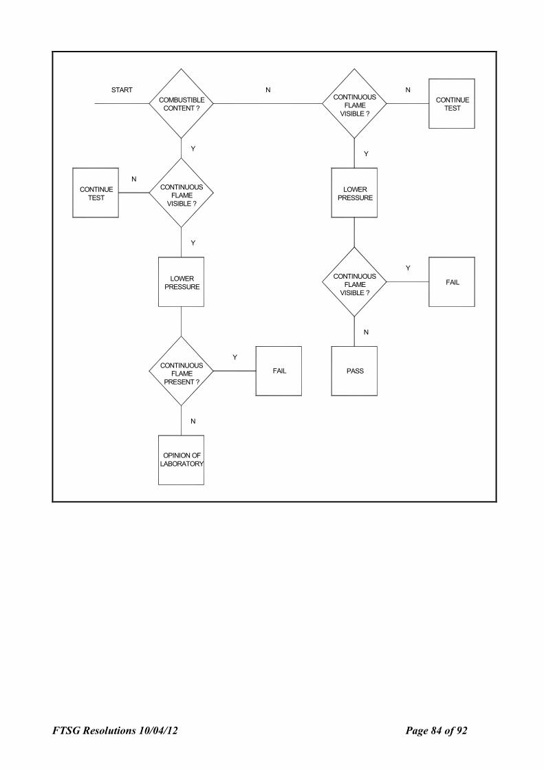
FTSG Resolutions 10/04/12 Page 84 of 92
LOWER
PRESSURE
OPINION OF
LABORATORY
N
CONTINUOUS
FLAME
PRESENT ?
Y
CONTINUE
TEST
Y
CONTINUOUS
FLAME
VISIBLE ?
N
Y
COMBUSTIBLE
CONTENT ?
CONTINUOUS
FLAME
VISIBLE ?
FAIL PASS
N
FAIL
LOWER
PRESSURE
Y
NCONTINUOUS
FLAME
VISIBLE ?
CONTINUE
TEST
NSTART
Y

FTSG Resolutions 10/04/12 Page 85 of 92
FIRE TEST STUDY GROUP (UK) RESOLUTION No
78
No. 78 Testing of insulated door assemblies to BS 476: Part 22: 1987.
STANDARD (S) TO WHICH APPLICABLE: BS 476 : Part 22
FTSG PROGRESSION DATES:
Agreed by Executive
Implemented
Outside bodies notified (if applicable)
Reaffirmed (if applicable)
Superseded/withdrawn
Superseded by (if applicable)
: 25-2-97
: 24-11-97
: FSH/22/5 24-11-97
Still Valid
REASON :
There are inconsistencies in testing resulting from a lack of clarification as to which section of BS 476
Part 22: 1987 is being used when carrying out tests on insulated door assemblies.
There are also inconsistencies in interpretation as to which components and/or areas of a door
assembly can be excluded in the 20% of the area that is not evaluated with respect to the insulation
criteria when testing to BS 476: Part 22: Section 7.
RESOLUTION :
When testing door assemblies to BS 476: Part 22: 1987, the sponsor shall agree with the laboratory
which section of the standard is to be used when conducting the test. Alternatively, sufficient
instrumentation shall be provided by the laboratory so that an insulated door assembly can be
evaluated as partially insulating or uninsulating and a partially insulated door assembly can be
evaluated as uninsulating.
When testing partially insulated door assemblies to BS 476: Part 22: 1987: Section 7, the door frame
shall not be included in the 20% of the total area of the door that is not evaluated with respect to the
insulation criteria, i.e. the temperature of the door frame shall be used in the evaluation of partially
door assemblies against the insulation criteria.
NOTE: The note to 7.6.1.1 allowing 20% of the area of the specimen not to be evaluated with respect
to insulation is followed by section 7.6.1.3 which calls up the thermocouples mounted on the door
frame to be used in the evaluation of partially insulated door assemblies with respect to the insulation
criteria.
FTSG Resolutions 10/04/12 Page 86 of 92
FIRE TEST STUDY GROUP (UK) RESOLUTION No
79
No. 79 - Fire resistance testing of asymmetrical specimens from one direction
STANDARD (S) TO WHICH APPLICABLE: BS
476: Part 22 or EN 1634-1.
ire resistance tests on timber and elements
FTSG PROGRESSION DATES:
Agreed by Executive
Implemented
Outside bodies notified (if applicable)
Reaffirmed (if applicable)
Superseded/withdrawn
Superseded by (if applicable)
25-2-97
24-11-97
BSI : 24-11-97
ammended 23/3/01
Still Valid
REASON :
There are inconsistencies in the applicability of results of tests carried out in one direction on
asymmetrical specimens that are required to resist fire from both sides. BS 476: Part 20 : 1987 -
amongst others - allows this if the ‘reason’ for choosing the more onerous direction is given in the
report. There are several problems with this approach:
1. The British Standard allows for a result on one direction to apply to another direction if the
‘reason’ is given in the test report. Such a ‘reason’ is in fact an opinion and therefore is not
permitted to be in a report of a test according to UKAS rules.
2. The worst direction of test for one criterion may not be the worst direction for another criterion.
Different end-users place different emphasis on different criteria.
RESOLUTION :
When testing single asymmetrical separating elements for fire resistance:
1. The test report will state that the result is only applicable to the tested direction, unless there is
a field of direct application associated with the test method which determines that the result is
also applicable to another direction. In such cases, the statement that the results are
applicable to another direction shall be contained in a field of direct application section of the
report.
2. If the sponsor requests that the result be applied to the direction not tested, or not covered by
any direct field of application, then that may only be satisfied by the preparation of an
assessment by the laboratory in accordance with Resolution 82.
3. Any assessment such as that defined in 2 above shall be separate from the main body of the
report, but may be included in one overall document for convenience.
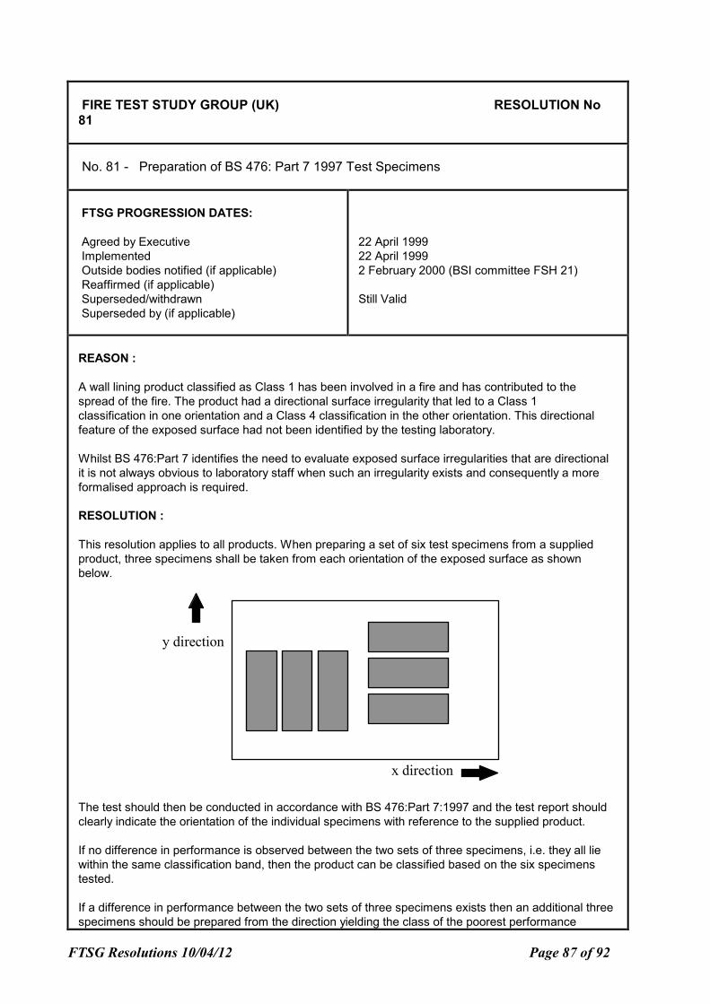
FTSG Resolutions 10/04/12 Page 87 of 92
FIRE TEST STUDY GROUP (UK) RESOLUTION No
81
No. 81 - Preparation of BS 476: Part 7 1997 Test Specimens
FTSG PROGRESSION DATES:
Agreed by Executive
Implemented
Outside bodies notified (if applicable)
Reaffirmed (if applicable)
Superseded/withdrawn
Superseded by (if applicable)
22 April 1999
22 April 1999
2 February 2000 (BSI committee FSH 21)
Still Valid
REASON :
A wall lining product classified as Class 1 has been involved in a fire and has contributed to the
spread of the fire. The product had a directional surface irregularity that led to a Class 1
classification in one orientation and a Class 4 classification in the other orientation. This directional
feature of the exposed surface had not been identified by the testing laboratory.
Whilst BS 476:Part 7 identifies the need to evaluate exposed surface irregularities that are directional
it is not always obvious to laboratory staff when such an irregularity exists and consequently a more
formalised approach is required.
RESOLUTION :
This resolution applies to all products. When preparing a set of six test specimens from a supplied
product, three specimens shall be taken from each orientation of the exposed surface as shown
below.
x direction
y direction
The test should then be conducted in accordance with BS 476:Part 7:1997 and the test report should
clearly indicate the orientation of the individual specimens with reference to the supplied product.
If no difference in performance is observed between the two sets of three specimens, i.e. they all lie
within the same classification band, then the product can be classified based on the six specimens
tested.
If a difference in performance between the two sets of three specimens exists then an additional three
specimens should be prepared from the direction yielding the class of the poorest performance
FTSG Resolutions 10/04/12 Page 88 of 92
FIRE TEST STUDY GROUP (UK) RESOLUTION No
81
(greatest flame spread). The classification of the exposed surface in this instance should be based on
the six samples taken from the same orientation.
Note: Sufficient material should be supplied for a further set of three specimens to be cut in either
direction.
FTSG Resolutions 10/04/12 Page 89 of 92
FIRE TEST STUDY GROUP (UK) RESOLUTION No 82
No. 82 - Use of PFPF Guide to Undertaking assessments
FTSG PROGRESSION DATES:
Agreed by Executive
Implemented
Outside bodies notified (if applicable)
Reaffirmed (if applicable)
Superseded/withdrawn
Superseded by (if applicable)
: 5-12-00
: 2-01-01
:
:
: Still Valid
:
REASON :
FTSG has invested considerable effort in developing and promoting the FTSG code on undertaking
assessments. This documents has been taken on board by the Passive Fire Protection Federation
and with only minor modifications has been endorsed as the way to undertake assessments in lieu of
fire tests.
The guide supersedes resolution 64a 1993 and should be the definitive document used for
undertaking assessments by FTSG members.
RESOLUTION :
When undertaking assessments, FTSG members agree to follow the PFPF guide to undertaking
assessments in lieu of fire tests as the document to control the production of assessments in their
organisation.
Reference must be made to the use of the guide in all assessments.
Resolution 64a: 1993 is withdrawn.
FTSG Resolutions 10/04/12 Page 90 of 92
FIRE TEST STUDY GROUP (UK) Resolution No. 83 No. 83 - Integrity failure via sustained flaming
FTSG PROGRESSION DATES:
Agreed by Executive Implemented Outside bodies notified (if applicable) Reaffirmed (if applicable) Superseded/withdrawn Superseded by (if applicable)
: 24-10-01 : 1-11-01 : : : :
TITLE: Integrity failure via sustained flaming
REASON : When evaluating a test specimen for integrity failure via sustained flaming, it is sometimes difficult to determine what constitutes the unexposed face. In some cases it can be a highly irregular surface with flaming in small cracks and fissures e.g. flaming within a narrow joint between two panels of a partition. In other cases the flaming may come from components which were not originally part of the unexposed face, but which have been revealed during the test. An examples of this is a double glazed unit comprising fire resistant glass on the exposed face and normal float glass on the unexposed face, where the unexposed face glass breaks and falls out revealing flaming components surrounding the fire resistant glass.
In cases such as these, the laboratory has to decide what constitutes the unexposed face and whether this may change as the test progresses. This resolution has been agreed In order to remove any inconsistencies between laboratories in defining what constitutes the unexposed face of the test specimen.
RESOLUTION : When conducting a fire resistance test, sustained flaming from the specimen should only be deemed as an integrity failure if it occurs on the unexposed face of the specimen. For this purposes, the unexposed face is any area which could be evaluated during the test using the roving thermocouple.
Consequently, if the flaming is contained within a gap in an element and one was not able to apply the roving thermocouple into that gap e.g. because it was too narrow, then this does not constitute failure and the flaming within that gap is ignored.
FTSG Resolutions 10/04/12 Page 91 of 92
FIRE TEST STUDY GROUP (UK) Resolution No. 84 No. 84 - Assessment of fire protection to structural steelwork
FTSG PROGRESSION DATES:
Agreed by Executive Implemented Outside bodies notified (if applicable) Reaffirmed (if applicable) Superseded/withdrawn Superseded by (if applicable)
: 15-05-03 : 15-05-03 : ASFP : : :
TITLE:
Assessment of the Fire Resistance Performance of materials used to protect structural steelwork
REASON : There is a need to ensure and demonstrate that FTSG members are all using the same principles when undertaking appraisals of materials used to protect structural steelwork.
RESOLUTION :
When undertaking an appraisal of a material, product or system used to protect structural steelwork, the results of any assessment made of the ability for any fire protection product to enhance the fire resistance performance of structural steel shall respect the following principles: I. the ‘stickability’ of the product shall be justified for the maximum period of fire
resistance claimed. No fire resistance performance shall be assessed if the product has not been proven to be able to stay on a stressed and deflecting beam or column for the maximum fire resistance period,
II. the scope of assessment of product thicknesses, steel section sizes and types, and the fire
protection periods shall not be significantly extrapolated beyond the range of the input data for these variables,
III. all the available test data shall be used in support of the analysis of the product performance
and selected data shall not been excluded without appropriate and reasonable justification, and IV. from a comparison of the predicted times and thicknesses for given steel section factors with
the times actually obtained in test, the analysis shall provide a reliable but conservative prediction of the test results from which it is derived.
FTSG Resolutions 10/04/12 Page 92 of 92
FIRE TEST STUDY GROUP (UK) Resolution No. 85 No. 85 - Interpretation of cotton pad application.
FTSG PROGRESSION DATES:
Agreed by Executive Implemented Outside bodies notified (if applicable) Reaffirmed (if applicable) Superseded/withdrawn Superseded by (if applicable)
: 15-5-03 : 15-5-03 : BSI FSH 22 28-5-03 :
TITLE: FTSG Interpretation of cotton pad application.
REASON:
The use of the cotton pad test, as defined in clause 10.4.5.2 of BSEN 1363-1: 1999 is ambiguous. The clause does not clearly define whether the cotton pad should be applied to surfaces where no crack or gap is present, in addition to cracks or gaps where hot gasses are passing through the specimen. This becomes an issue when radiation levels from uninsulated surfaces, especially uninsulated glazing, are sufficient to ignite a cotton pad, without the presence of cracks or gaps. Concern has been raised regarding the possibility of igniting combustible components of the specimen, adjacent to the cotton pad, on the unexposed face of the specimen, as failures due to glowing or flaming of the cotton pad are subsequently discounted for classification of non-insulating elements, under the rules of the classification standard (prEN 13501-2: May 2002).
RESOLUTION: The cotton pad shall be applied throughout the test, to all surfaces, regardless of whether or not cracks or gaps are present. Care should be taken to avoid, if possible, igniting combustible components on the unexposed face of the specimen adjacent to the cotton pad, due to flaming of the pad. The pad shall therefore be positioned to reduce this possibility, providing the area where the pad is applied has a similar surface temperature to those areas where the combustible materials are located. For instance, positioning the pad in a lower area of a glazed panel to reduce the risk of igniting the beading at the head by rising flames from the pad. However, if there are any cracks, gaps, or hot-spots in the higher area of the glazed panel, the pad shall be applied to these areas. The pad should be removed immediately once glowing or flaming of the pad occurs. When there is any doubt of whether the cotton pad would or would not glow/ignite, the pad shall be applied at least in the final minute prior to each classification duration stated in the classification standard.