fs alu 5200-dk e rc 2 - siegenia · 529 922 530 529 922 530 529 922 530 701 517 802 519 518 502 504...
TRANSCRIPT

BD 3.5
FBS
BD 5KPW
ALU 5200-DK E RC 2
H48.5200LS024en
Page 110.2015
H48
.520
0LS0
24en
/1
Ass
embl
y in
struc
tions
H
48.5
200L
S024
en
The anti-intruder turn-and-tilt hardware for aluminium windows and French doors.
Application for electrical test according to DIN EN 1627ff RC 2, RC 2 N
Size range It is essential to adhere to the details of the system provider.
Windows min. max.
French doorsmax.
Sash width (mm) 365 to 1600 1300
Sash height (mm) ALU handle lockable (101/103) 730 to 2000 2400
Sash height (mm) TITAN handle lockable (105) 795 to 2000 2400
Sash weight (kg) max. 130/150 max. 130/150
Table of contentsSize ranges ................................................................................. 1Hardware overview .................................................................... 2Hardware list and design variations .......................................... 3Jigs and installation dimensions for sash brake ......................... 4Positions of the locking parts LM-E ............................................. 5Sash dimensions ......................................................................... 6Frame dimensions ....................................................................... 7Assembly instructions gear set M6 LM-E (H3) ........................... 8
The following information from the aluminium planning manual must be observed: Guidelines of the German quality association for locks and hardware (Gütegemeinschaft Schlösser und Beschläge e. V) - Document no. H45.4200LS001EN Application diagrams: - Sash weight up to max. 100 kg: Document no. H58.AWDLMS003EN- Sash weight up to max. 130 kg: Document no. H58.AWDLMS004EN- Sash weight up to max. 150 kg: Document no. H58.AWDLMS005EN Required documentation: ALU 5200-DK FBS-EUL Sash weight up to max. 100 kg/130 kg - Document no. H48.5200LS001EN / H48.5200LS014ENALU 5200-DK FBS-EUL Sash weight up to max. 150 kg - Document no. H48.5200LS007ENGear set M6: - Document no. H48.ZubhLS005ENBasic safety notes: - Document no. H45.5200LS001EN Abbreviations: - Document no. H45.5200LS002EN Adjustment options: - Document no. H45.5200LS004ENProfile recommendation:- Document no. H48.ZubhLS008EN Updated directory of the documents: - Document no. H45.5200LS005EN
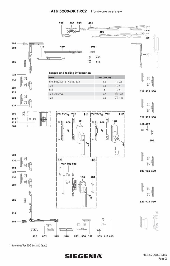
ALU 5200-DK E RC2 Hardware overview
H48.5200LS024en Page 2
1) Is omitted for ESG LM M6 (620)
Torque and tooling information
Items Nm (± 0.25)
410, 505, 506, 517, 518, 802 1.5 2.5
908 2.5 4
412 4 4
904, 907, 922 2.7 PZ2
923 2.5 PH2
922 530 529
530 922529
604
412
413 412
505
505
401
400
410411
413
923
907 622 620
904
922529 530
1)
1)
505 412 413
922529 530
922529 530
922529 530
701
519802517 518
502
504
506
922
530
529
922
922
530
529
922
530
529
530
529
505
515
502
505
412413
500
500
101 103
105
H1 H2
H3
604
908
915 907 604
908
915 907

H48.5200LS024en
Page 3
ALU 5200-DK E RC2 Hardware list
Design variations for handle support ALU (915)
USH ZX
< 7 mmX
7.1 - 8.5 mm
Material-No. Material-No.
7 - 10 mm< 2 mm MFHA0010-100200 MFHA0010-100200
2.1 - 3 mm MFHA0010-100200 MFHA0020-100200
> 3 mm MFHA0010-100200 -
12 mm - MFHA0030-100200 -
USH
Item Piece Designation Material-No. VE Material-No. VE
1 Hinge side ALU 5200 Hinge side ALU 5200 without positioning
H1
101 0...1 Handle ALU Si-line lockable Only use in combination with coupling set ALU-E See ALU handle overview, document no.: H48.ZubhLS007en
in ALU planning manual
H2
103 0...1 Handle ALU GLOBE, lockable
H3
105 0...1 Handle TITAN lockable Only use in combination with ALU-E gear set(Torque min. 100 Nm) ( 7mm x 25, cam ∅10 mm)
701 1 VSU/BSO corner drive 859391 1 266076 20
depe
ndin
g on
FB/
kg
400 0...1 Top stay ALU 5200 size 20 FB > 365 ≤ 600 ≤100 kg 884805 1 273 098 20
401 0...1 Top stay ALU 5200 size 35 FB > 600 ≤ 1600 884782 1 314 203 20
0...1 Additional stay LMFB > 1250 with top stay size. 35 ≤ 100 kg FB > 1020 with top stay size 35 > 100 kg 857076 1 247006 10
410 1 Additional stay 411 1 Striker plate 412 1 Locking cam413 1 Eccentric rivet
1 VS ALU-DK FBS-EUL KPW MMVS0450-100010 1 MMVS0450-100030 20
500 1 DK locking bolt502 2 EUL clamping piece504 1 VSO FBS corner drive505 1 Striker 506 1 Striker EUL VSO515 1 VSU corner drive517 1 Run up block518 1 Tilt locking part519 1 Tilt lock DK
H1/
H2
0...1Coupling set ALU-E (without FBS on gear)
Only use in combination with H1/H2 MMKL0070-100010 1 MMKL0070-100030 20
604 1 Coupling bracket E M6907 2 M6 coupling screw908 2 M5 x 12 cheese head screw
H3
0...1Gear set ALU-E(without FBS on gear)
Only use in combination with H3 MMGI0060-100010 1 MMGI0060-100030 20
620 1 ESG LM M6622 1 Anti-drill guard904 2 M5 x 35 countersunk screw907 2 M6 coupling screw923 2 Countersunk tapping screw B 3.9 x 13
4...10
Locking part ALU-E A0004 MMVR0050-100010 1 MMVR0050-100030 20
Locking part ALU-E A0006 MMVR0060-100010 1 MMVR0060-100030 20
Locking part ALU-E A0022 MMVR0070-100010 1 MMVR0070-100030 20
529 1 Locking part E530 1 Striker E922 2 Countersunk screw FDS M5 x 14.5
depe
nden
t on
syste
m
0...2 Locking part ALU FH > 1250 mm (recommendation) - 1 317556 20
412 1 Locking cam
413 1 Eccentric rivet
505 1 Striker0...1 MV ALU-RB/SF FB > 1250 mm (recommendation) 894316 1 303917 20
412 1 Locking cam413 1 Eccentric rivet505 2 Striker
Accessories
802 0...1 Sash lifter ALU (see drawing no. H48.ZubhLS014en) MMFH0010-100010 1 MMFH0010-100030 20
915 0...1 Handle support ALU Only use in combination with H1/H2 - - (see below) 200

ALU 5200-DK E RC 2 Number and positions of the ALU-E locking parts
H48.5200LS024en
Page 4
FB > 900
FH > 2000
FH > 1400
FH > 900
FHFB
365 ≤ 900FB
> 900
> ...1) ≤ 1400 4 6
> 1400 ≤ 2000 6 8> 2000 - 2400 8 10
1) For size ranges, see table on page 1
Designation Material no.
1. Jig ALU-E-EL for sash (max. 10 per sash) 156926
2.1 Jig ALU-EB-E (3.5 mm) for frame (hole ∅ 3.5) (fig. 4) MARB0060-500010
2.2 Jig ALU-EB-E (4.2 mm) for frame (hole ∅ 4.2) (fig. 5) MARB0040-500010
1. Use on sash
A Mounting and securing the sash.B Insert jig ALU-E-EL into locking parts E (529) (see fig. 1).C Switch gear vertically upwards (180°).D Switch gear horizontallyE Close sash without changing handle position.F Make markings for jig ALU-EB-E on the frame (see fig. 2).G Open sash.H Remove jigs ALU-E EL.
2.1/2.2 Use on frame
Position jigs ALU-EB-E and (see fig.3) and drill boreholes for strikers E (530) (see fig. 4) with ∅ 3.5 or (see fig. 5) with ∅ 4.2 (remove markings).
Installation of the jigs ALU-EL on the sash
Installation of the jigs ALU-EB-E to the frameFig. 4 (2,1) Fig. 5 (2.2)
∅ 3.5 ∅ 4.2

ALU 5200-DK E RC 2 Jigs and installation dimensions for sash brake ALU
H48.5200LS024en
Page 5
50,2
7,5
Designation Material no.
Punching tool E - ∅ 5.2 operating rod punch hole 141267
- Cropping
- Punching 50.2
Suitable drive: - Punch hole for
BST 105 (15 mm travel) Locking parts E
or
Multi-purpose punching machine - ∅ 5.2 operating rod punch hole 157398
- Cropping
- Punching 50.2
- Punch hole for
Locking parts E
Installation dimensions for sash brake ALU
Opening angle 90°
Measurements in mm X Y
Sash brake ALU short sash width 800 - 1000 60 104
Sash brake ALU long sash width 1001 - 1600 124 208
Installation of the sash brake ALU on the hinge side at the bottom (BSU)
There is a risk of injury if the window sash falls out!
-The sash limiter ALU can only be installed on the hinge side, bottom.
For missing details on the sash brake ALU, see aluminium planning manual under accessories drawing no. H48.ZubhLS017en
Guiding piece
Stop
Top hinge block

ALU 5200-DK E RC 2 Sash dimensions
H48.5200LS024en
Page 6
S5 = FB/2 - 150 (FB > 900)
FB/2 - 505
FH/3
- 16
0 (F
H >
200
0)FH
/3 -
173
(FH
> 2
000)
FH/2
- 18
0
S4 =
FH
- 34
8
(FB > 900) 50
50,2
S1 =
G1
- 248
S2 =
G2
- 213
G1
- 110
380
(FH
≤ 1
400)
(m
in. F
H/3
) (H
1/H
2)
350
(FH
≤ 1
400)
(H
1/H
2)
≤
≤
328
FB (sash width) min. 365
FH (
sash
hei
ght)
S3 = Top stay ALU 5200 Size. 20 FB - 338= Top stay ALU 5200 Size. 35 FB - 506 = with additional stay ALU for FB - 664
(> 100 kg/FB > 1020 mm)
FB/2 - 426MV 3)
(FB > 900 ≤ 1250)(FH > 1250)
MV
3)
1) G1 ≤ G22) G1 < G23) Installation recommendation for the centre locks see page 3.
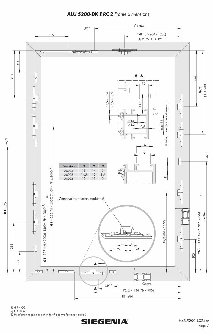
ALU 5200-DK E RC 2 Frame dimensions
H48.5200LS024en
Page 7
MV 3)
MV
3)
1) G1 ≤ G22) G1 < G23) Installation recommendation for the centre locks see page 3.
118
205 FH
/2 -
118
(140
0 <
FH <
200
0)26
6
498 (FB > 900 < 1250)
FB/2 - 92 (FB > 1250)
241
10
min
. 18
255
125
FB/2 + 134 (FB > 900)
FB - 284
233
127
13 13
24 24
76
< 1,
5 (
3,5
)>
1,5
( 4
,2)
3,54,2 9,5
A
A
A - A
MV 3)
Centre
Centre
Cen
tre
MV
3)
Observe installation markings!
Version X Y ZA0004 18 14 3A0006 14.5 10 3.5A0022 15 12 3
(Ove
rall
fram
e cl
eara
nce
dim
ensio
n)

ALU 5200-DK E RC 2 Assembly instructions gear set M6 LM-E (H3)
H48.5200LS024en
Page 8
SIEGENIA-AUBI KG Industriestraße 1-3 D-57234 Wilnsdorf Telephone +49 271 39 31-0 - Fax +49 271 39 31-3 33
Assembly instructions
Preparation A Rework lockable window handle (105) and ESG LM M6 (620)
on sash according to dimensions (fig. 1 and 4).
B Adjust the length of the square spindle to the profile used. Shorten if necessary.
C Process operating rods S1 and S2 according to dimensions.
D Screw anti-drill guard (622) with countersunk tapping screw PH 3.9 (923) to ESG LM M6 (620)
For positioning of locking parts E (529) see operating rods S1 and S2 (fig. 2+3).
Sash E ESG LM M6 (620) into the milling groove provided (fig. 4).
Mount ESG LM M6 (620) with coupling screws M6 (907) to the operating rods.
F Mount lockable window handle (105) with countersunk screws M5 x 35 (904).
Frame For FH > 1250 mm (recommendation), position striker (505) according to dimensions (fig. 5) and clamp into place
with the grub screw.
1) G1 ≤ G22) G1 < G23) Installation recommendation for the centre locks see page 3.
S1 =
G1
- 233
S2 =
G2
- 238
G1
+ 7
6
G2
min.
415
G1
min.
380
MV
3)
Fig. 1 Fig. 2 Fig. 3 Fig. 4 Fig. 5
Ha
ndle
po
sitio
n G
1H
and
le p
osi
tion
G2