from large natural draft cooling tower shells to chimneys
TRANSCRIPT
Proceedings of the International Association for Shell and Spatial Structures (IASS) Symposium 2009, Valencia Evolution and Trends in Design, Analysis and Construction of Shell and Spatial Structures
28 September – 2 October 2009, Universidad Politecnica de Valencia, Spain Alberto DOMINGO and Carlos LAZARO (eds.)
From large natural draft cooling tower shells to chimneys of solar upwind power plants
Wilfried B. KRAETZIG*, Reinhard HARTEa, Ulrich MONTAGb, Ralf WOERMANNb
*Ruhr-University Bochum, Structural Mechanics
D 44780 Bochum, Germany E-mail Address: [email protected]
a University of Wuppertal, Structural Mechanics, D 42285 Wuppertal, Germany b Kraetzig & Partners Consulting Engineers, Buscheyplatz 9-13, 44801 Bochum
Abstract Natural draft cooling towers (NDCTs) presently form the world-largest RC shell structures, solar updraft power plants (SUPPs) will do this in future. The paper starts with explanations of the working principles of NDCTs and SUPPs. In industrialized countries with strong legal emphasis on sustainable power production technologies, NDCTs are widely spread, while SUPPs represent future solar power generation concepts in the world’s tropical areas, using solar irradiation as power plant fuel. Consequently, the paper elaborates on recent German NDCTs, under them the world-highest tower shell. The design of such high-efficient RC tower shells will be explained including their critical response characteristics. The paper then changes to future SUPPs, describing the structural components of their solar chimneys, followed by a sketch of some of their critical response characteristics. The aim of this presentation is to draw the readers’ attention to extremely large shell structures (Mega-shells), present and in future, and to demonstrate their close structural mechanics relationship to each other. Keywords: RC shell structures, Cooling tower shells, Solar updraft chimneys, Giga towers, Shell instabilities, shell vibrations, non-linear shell behavior.
1. Introduction Since the re-unification of Germany 1990, most of the thermal power stations in the former DDR, mainly fuelled by lignite, had to be renewed. Presently in Germany’s West, several thermal power plants are rebuilt for improvement of their efficiency. These new power stations are fuelled either by hard coal or by lignite; the maximum net electric capacity per power block is up to 1.100 MW. All plants are equipped with high-rise (wet) natural draft cooling towers (NDCT) up to heights of 200 m, mainly for environmental and for
2

Proceedings of the International Association for Shell and Spatial Structures (IASS) Symposium 2009, Valencia Evolution and Trends in Design, Analysis and Construction of Shell and Spatial Structures
economical reasons. With these NDCTs, the net electric degree of efficiency of a power block lies closely below 45%. Forerunners of such high-efficient NDCTs serve at French, German and Swiss nuclear power stations.
Figure 1: RWE Power Station Niederaussem under construction in 2001 (Photo RWE)
Since several decades Kraetzig & Partners are involved in analysis, design and construction of high-rise NDCTs. Figure 1 shows presently with 200 m of elevation our world-highest tower at the RWE Power Station of Niederaussem, a 960 MW lignite base load plant.
Figure 2: Scheme of thermal power station with NDCT and cleaned flue gas injection
In such thermal power stations due to Figure 2, heated steam drives the turbo-generators which then produce electric power. To create an effective heat sink at the (cold) end of the turbine for a high-effective process, the off-worked steam has to be condensed and recycled into the boiler. This condensation requires a permanent supply of cooling water for the condenser, which is warmed up therein and re-cooled in a NDCT For this purpose, the warmed water is distributed evenly over the NDCT’s fill, therein separated to thin water drops, which then drip down from the fill as a fine rain through the
3

Proceedings of the International Association for Shell and Spatial Structures (IASS) Symposium 2009, Valencia Evolution and Trends in Design, Analysis and Construction of Shell and Spatial Structures
uprising cooler air, as Figure 3 elucidates. Finally it is collected in the water basin for re-use in the condenser, Kraetzig et al [7]. The falling water drops cool down by evaporation
Figure 3: Classical wet NDCT with RC water distribution and fill construction and convection, releasing the residual heat of the power generation process via the inner atmosphere of the tower directly into the air of the plant’s environment. So NDCTs avoid the former nature-destroying thermal pollution of rivers, lakes or seashores by reducing their oxygen contents under toxic life-limits.
Figure 4: Working scheme of a SUPP
But such high-efficient NDCTs serve an additional purpose. Due to legal regulations in Germany and other EU countries since over 25 years, all flue gases have to be cleaned from combustion products of sulphur (S) and nitrogen (N). This cleansing is favourably performed in chemical gas-washing-plants, by which the temperature of the flue gas cools down from 280°C to below 90°C, such that its thermal energy becomes insufficiently low
4
Proceedings of the International Association for Shell and Spatial Structures (IASS) Symposium 2009, Valencia Evolution and Trends in Design, Analysis and Construction of Shell and Spatial Structures
for release into the environment via a smoke-stack. But by injection of the cleaned flue gases into the NDCT, its vapour easily carries them up into heights of above 300 m, with certain durability consequences for the high-performance RC of the tower shell. Consequently, modern high-performance NDCTs serve two purposes: the discharge of the residual heat from the cooling water directly into the air-environment and the like-wise discharge of the cleaned flue-gases. For both aims, the incomprehensively huge cooling tower RC shells with their internal updraft play the central role. Also in solar updraft power plants (SUPPs) this internal upwind in the RC chimney is the driving force, here for solar power generation. The general working concepts of SUPPs is illustrated in Figure 4. They consist of a collector area (CA), the turbo-generators as power conversion units (PCU), and a solar chimney (SC). In the CA, a large glass-covered area, solar UV-irradiation heats the collector ground and consequently warms up the air inside the CA, which then streams towards its center. There, in the PCU, the kinetic energy of the air-stream is partly transformed into electric power. A pressure-sink at the PCU outlet is created by the updraft in the huge SC for increased effectiveness.
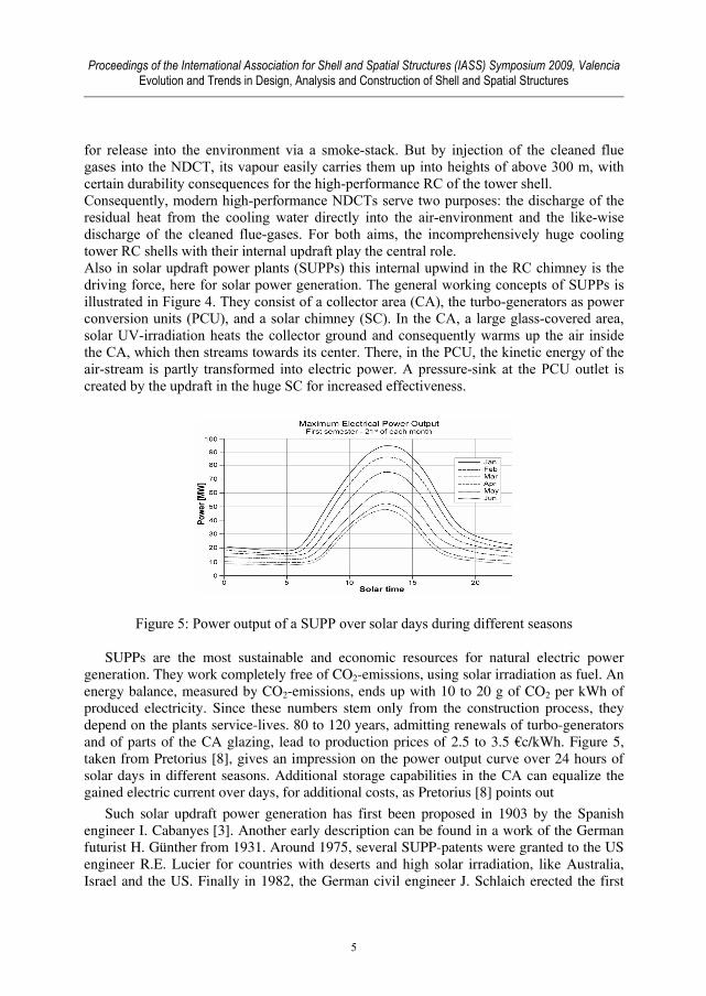
Figure 5: Power output of a SUPP over solar days during different seasons
SUPPs are the most sustainable and economic resources for natural electric power generation. They work completely free of CO2-emissions, using solar irradiation as fuel. An energy balance, measured by CO2-emissions, ends up with 10 to 20 g of CO2 per kWh of produced electricity. Since these numbers stem only from the construction process, they depend on the plants service-lives. 80 to 120 years, admitting renewals of turbo-generators and of parts of the CA glazing, lead to production prices of 2.5 to 3.5 €c/kWh. Figure 5, taken from Pretorius [8], gives an impression on the power output curve over 24 hours of solar days in different seasons. Additional storage capabilities in the CA can equalize the gained electric current over days, for additional costs, as Pretorius [8] points out
Such solar updraft power generation has first been proposed in 1903 by the Spanish engineer I. Cabanyes [3]. Another early description can be found in a work of the German futurist H. Günther from 1931. Around 1975, several SUPP-patents were granted to the US engineer R.E. Lucier for countries with deserts and high solar irradiation, like Australia, Israel and the US. Finally in 1982, the German civil engineer J. Schlaich erected the first
5

Proceedings of the International Association for Shell and Spatial Structures (IASS) Symposium 2009, Valencia Evolution and Trends in Design, Analysis and Construction of Shell and Spatial Structures
prototype-SUPP in Manzanares/Spain, with a 200 m high SC, a 700 m wide CA, and a maximum power output of 50 kW. Schlaich’s team operated this plant very successful for more than 6 years, see Schlaich [11]. Figure 6 gives an impression of this prototype plant, which contained a single PCU with vertical turbine axis, a solution also considered for bigger plant designs. More recent designs show a series of single CPUs with horizontal axes around the tower perimeter, an arrangement more advantageous for turbine installation, control, maintenance, and economy of energy output.
Figure 6: J. Schlaich’s SUPP prototype from 1982 at Manzanares/Spain
In spite of the successful pioneering work of Schlaich, no professional SUPP has been errected, up to now. General aspects of SUPPs are summarized in [Wikipedia: Solar updraft towers], including a discussion of their pros and cons. Recent compilations of SUPPs can be found in Schlaich et. al. [9], and the basic source about this power generation from the 1990’s is still Schlaich [10]. The principal doubts of many laymen, namely if a tower of height of more than 1 000 m can be built at all, has considerably calmed down since the Burj Dubai skyscraper in the United Emirates of 818 m of elevation had been completed.
2. Structural elements of a cooling tower shell The NDCT Niederaussem on Figure 1 shall now serve to explane the tower components. Obviously from Figure 7, the tower height is 200 m. Its base diameter measures 152.54 m, that one of the shell 136.00 m, and the top opening is 88.41 m wide. The shell contains two openings for the flue gas inlets of 9.00 m diameter each. Both the outer and inner shell faces add up to areas of about 60 000 m² each. The cooling tower shell is composed of two hyperbolic shells of revolution, meeting at the throat. It exhibits wall thicknesses between 0.22 m and 0.24 m, increasing towards the lower shell rim and around the flue gas inlets. On its top the shell is stiffened by a U-shaped
6

Proceedings of the International Association for Shell and Spatial Structures (IASS) Symposium 2009, Valencia Evolution and Trends in Design, Analysis and Construction of Shell and Spatial Structures
edge member, with hangover of 1.51 m towards the interior and shank-height of 1.20 m. To prevent cracking in the upper third of the shell due to wind vibrations, this edge member is pre-stressed by 4 SUSPA tendons, 8×150 mm² cross-section from St 1 570/1 770 N/mm². At the lower end the shell thickness increases to 1.16 m. The entire shell consists of acid-resistant high-performance RC of compression strength 85 N/mm², called ARHPC 35/85.
Figure 7: Dimensions of the world-largest NDCT at Niederaussem
The tower shell is supported by 48 meridional columns of 14.68 m of height, cast of RC 45/55. Their thickness ranges from 1.16 m on top up to 3.10 m above foundation, their width is 1.40 m. All columns stand on a reinforced concrete ring-base of 6.60 m × 1.80 m, resting on consolidated gravel soil, after partly exchange of softer soil. Along the water inlets and outlet, the ring-width is enlarged, leading to a circular non-symmetric foundation. The interior of the NDCT is filled by the water basin to collect the re-cooled water. Its plate and wall consist of water-proof RC 30/37 with 0.20 m of thickness, founded on a 0.15 m concrete base layer of C 12/15 over an anti-freeze stratum of 0.30 m of thickness. Fill construction and water distribution rest on the basin plate, they are constructed as prefabricated RC beam-column structure, see Kraetzig et al [7], also furnished of high-performance concrete ARHPC 35/85, Busch et al [2]. In the last decennium several of these high-efficient NDCTs have been designed by Kraetzig & Partners. Two of them, the NDCTs of the RWE (double block) Power Station Neurath, are elucidated in more detail in Figure 8, which shows the main dimensions of both NDCTs of 173.20 m of elevation. Each tower contains only one entrance for the flue gas injection, and is supported by 36 vertical columns. Although both NDCTs are smaller
7

Proceedings of the International Association for Shell and Spatial Structures (IASS) Symposium 2009, Valencia Evolution and Trends in Design, Analysis and Construction of Shell and Spatial Structures
than that one in Niederaussem, they serve lignite power blocks of 1 100 MW each.Further details about the shells’ wall thicknesses, the dimensions of the RC columns and the pre-stressed upper edge member can be found in Figure 8. Figure 9 adds further dimensions and information on the RC materials for the cooling tower shell, their supports and corresponding pedestals, as well as for the ring-foundation
Figure 8: Dimensions of the RWE NDCTs for power blocks F and G at Neurath
Figure 9: Geometric and material data of NDCTs for power blocks F and G at Neurath
8

Proceedings of the International Association for Shell and Spatial Structures (IASS) Symposium 2009, Valencia Evolution and Trends in Design, Analysis and Construction of Shell and Spatial Structures
Figure 10 finally shows the NDCT-site in Neurath in early summer 2007, in front of the boiler houses under construction. Detailed insights into design, construction and execution of the cooling towers at Neurath can be found in Woermann et al [12]. We conclude and stress, that in the last decennium in Germany new concepts for NDCTs had been developed, with incomparably great efficiency, economic and service qualities.
Figure 10: RWE double blocks at Neurath under construction in summer 2007
3. Loads on NDCT shells and structural behavior Since over 30 years, NDCTs in Germany are designed due to VGB regulations; the most recent one is [13]. Typical load actions will now be counted up and explained: ● Dead weight D is determined by the self-weight of the shell wall (25.0 kN/m³) including the upper edge member and the wind ribs. ● Wind loading We, Si consists of the external pressure distribution we(z,θ) = cpe(θ)·φ·FI·qb(z), (1) and the internal suction si = wi = cpi·FI·qb(H). (2)
In (1), cpe(θ) stands for the normalized wind pressure distribution over the circumference θ, φ for the dynamic amplification (Neurath: 1.084), FI for the interference factor determined in wind-tunnel tests, and qb(z) for the design wind pressure over height z. In (2) we use cpi as internal suction coefficient and qb(H) for the stagnation pressure on tower top. Since NDCTs are often neighbored by high buildings, like boiler houses, FI and qb(z) generally depend on the wind direction leading to non-axisymmetric reinforcements in the shell.
9
Proceedings of the International Association for Shell and Spatial Structures (IASS) Symposium 2009, Valencia Evolution and Trends in Design, Analysis and Construction of Shell and Spatial Structures
● Temperature effects T: Because RC is crack-sensitive to temperatures, the following service states are considered for the design of NDCTs, see VGB [13]: Service temperature TOP: T0
OP = -15 K, ΔTOP = +33 K, Summer shut down TS: T0
S = +22 K, ΔTSeff= -25 K,
Winter shut down TW: T0W = -39 K, ΔTW = 0 K.
Caused by plant services the internal shell face is warmer than the external one; in summer shut downs this will be reversed. ● Shrinkage effects S in the (fresh) RC shell may lead to residual stress states and thus to shell cracking, if tension strength is exceeded. Design prescription of an equivalent temperature decrease of -15 K will safely avoid such early shell damage. ● Soil settlements B of external origin may effect NDCT shells in very negative sense, because of the pure size of modern NDCTs, of heavy neighboring loads from boiler houses, coalbunkers, etc., or from underground mining Such settlements have to be predicted in advance and then applied as design input, see Gould et al [4]. ● Seismic actions E may heavily influence the tower shell, especially the connection of the columns to the shell. Generally, possible earthquake excitations are code-given or predicted by expertises of geo-physicists and then considered in the design. ● Construction loads M will stem from guys of the central tower crane which serves the building site on tower top, or from anchoring of the self-climbing scaffold and formwork. All described loads may endanger NDCTs, and thus have to be considered in the FE analysis model as bases of a safe design. The finally applied FE models are rather comprehensive, enclosing the entire structure, the foundation and soil. So their number of DOFs is often over 100 000. Because of complicated soil conditions, of the cooling water inlet and the outlet locks, the foundation usually is non-rotational symmetric.
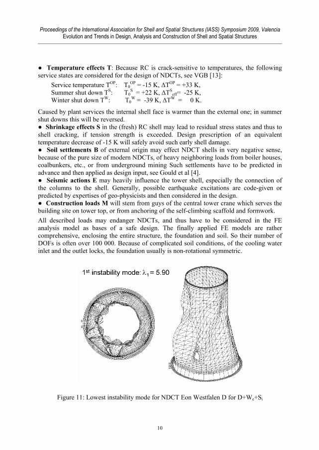
Figure 11: Lowest instability mode for NDCT Eon Westfalen D for D+We+Si
10

Proceedings of the International Association for Shell and Spatial Structures (IASS) Symposium 2009, Valencia Evolution and Trends in Design, Analysis and Construction of Shell and Spatial Structures
For a safe, reliable and durable design, limit states of failure and of serviceability are the design basis, distinguishing permanent respectively temporary design situations. Because of the thinness of the shell wall, also structural stability requires high attention. This safety concept follows the European standards EC 1, 2, and the German one DIN 1055-100, all included in the VGB guide-line [13]. To draw the readers’ attention to the degree of detailing, required for a safe design of modern NDCTs, we show the lowest instability mode (Figure 11), some linear vibration modes (Figure 12), and geometrically as well as materially non-linear deformations, in Figure 13 immediately before failure.
Figure 12: Three lowest natural vibration modes for NDCT Eon Westfalen D
Figure 13: Non-linear deformation of NDCT Niederaussem for D+ΔT45K+2.30We
11

Proceedings of the International Association for Shell and Spatial Structures (IASS) Symposium 2009, Valencia Evolution and Trends in Design, Analysis and Construction of Shell and Spatial Structures
4. Structural elements of solar chimney shells In the last 30 years J. Schlaich and his team [9, 11] have influenced the development of SUPPs with thorough investigations and admirable pre-designs, mentioned in section 1. Contributions of the authors of this paper in the last decade were related to the transfer of insights from designs of many NDCT-projects to solar chimneys. The aim was to render the solar tower resistance more effective, in order to reduce investment costs of SUPPs.
Figure 14: From the world-highest NDCT to pre-designs of future SUPPs
Figure 15: A small solar tower of 500 m of height
12

Proceedings of the International Association for Shell and Spatial Structures (IASS) Symposium 2009, Valencia Evolution and Trends in Design, Analysis and Construction of Shell and Spatial Structures
Figure 14 gives an overview over these attempts, demonstrating the way from NDCTs to chimneys of SUPPs up to an elevation of 1 500 m. The smallest solar chimney pre-designed by Kraetzig &Partners on Figure 15 has a height of 500 m, and is just on the limit of profitability, compared to parabolic solar reflector plants. With a collector of around 6 km in diameter, and in deserts with at least 2.4 MWh/a of solar irradiation input, such plant will deliver a peak power of approximately 32 MWp (annual work of 110 GWh).
Obviously, such solar towers are closely related to shape-strength-oriented designs of high NDCTs. The smallest diameter at the throat is 120 m, and the wall thickness increases from 0.25 m gradually to 0.60 m, for concrete quality of C 30/37. The tower shell is shape-optimized like for NDCTs, has an upper edge member and three additional intermediate stiffening rings. The turbo-generators are placed on the tower foundation around the footing perimeter, to reduce inflow losses and avoid different settlements.
Figure 16: A power tower of 1 000 m of elevation for a 200 MWp solar plant
Another recent pre-design from our engineering office is shown in more detail in Figure 16, a 1 000 m high RC solar chimney. With collector size of 6 000 m of diameter it shall produce a peak power of 200 MWp (annual work of 600 GWh). Shortly above the throat at 400 m of height the shell diameter is 130 m wide, at the upper rim 145 m. Below 400 m the tower shell widens in strength-optimized hyperbolic shape to a foot-diameter of 260 m. The wall thickness of high-performance RC 70/85 varies from 0.25 m to 0.65 m, as also detailed in Figure 16. In addition to the upper edge member, 9 intermediate RC ring-stiffeners are applied, fixed on the outer shell face. 16 turbo-generators deliver the mentioned plant capacity, see Backström et al [1].
13

Proceedings of the International Association for Shell and Spatial Structures (IASS) Symposium 2009, Valencia Evolution and Trends in Design, Analysis and Construction of Shell and Spatial Structures
Figure 17: Meridional (n22 W) and in-plane shear (n12 W) forces for 500 m tower
Figure 18: Instability modes for 500 m tower, still un-optimized wall thickness
5. Some typical response characteristics of solar chimney shells Types of loadings on SUPP-shells are very much the same as on NDCTs. The important difference is formed by the stiffening rings of solar tower shells, absolutely necessary for safety and economy of the design. These intermediate stiffeners first serve for a more cosine-like distribution of the meridional forces around the circumference under wind loading We, as observable in Figure 17. The second important purpose is the increase of the
14
Proceedings of the International Association for Shell and Spatial Structures (IASS) Symposium 2009, Valencia Evolution and Trends in Design, Analysis and Construction of Shell and Spatial Structures
stability safety by localization of the buckling modes, as exemplified in Figure 18 for the load combination (D+We+Si). For tower designs without ring-stiffeners one would recognize, that instability modes dominate the entire shell, such that the concrete quality for this alternative had to be increased to a high performance RC 90/105.
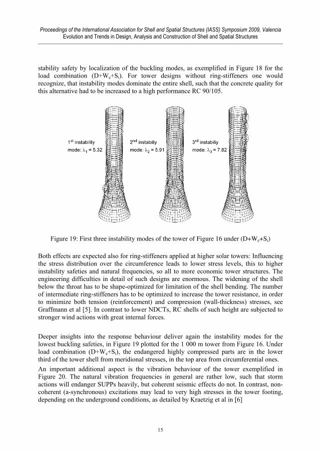
Figure 19: First three instability modes of the tower of Figure 16 under (D+We+Si)
Both effects are expected also for ring-stiffeners applied at higher solar towers: Influencing the stress distribution over the circumference leads to lower stress levels, this to higher instability safeties and natural frequencies, so all to more economic tower structures. The engineering difficulties in detail of such designs are enormous. The widening of the shell below the throat has to be shape-optimized for limitation of the shell bending. The number of intermediate ring-stiffeners has to be optimized to increase the tower resistance, in order to minimize both tension (reinforcement) and compression (wall-thickness) stresses, see Graffmann et al [5]. In contrast to lower NDCTs, RC shells of such height are subjected to stronger wind actions with great internal forces.
Deeper insights into the response behaviour deliver again the instability modes for the lowest buckling safeties, in Figure 19 plotted for the 1 000 m tower from Figure 16. Under load combination (D+We+Si), the endangered highly compressed parts are in the lower third of the tower shell from meridional stresses, in the top area from circumferential ones. An important additional aspect is the vibration behaviour of the tower exemplified in Figure 20. The natural vibration frequencies in general are rather low, such that storm actions will endanger SUPPs heavily, but coherent seismic effects do not. In contrast, non-coherent (a-synchronous) excitations may lead to very high stresses in the tower footing, depending on the underground conditions, as detailed by Kraetzig et al in [6]
15

Proceedings of the International Association for Shell and Spatial Structures (IASS) Symposium 2009, Valencia Evolution and Trends in Design, Analysis and Construction of Shell and Spatial Structures
Figure 20: First three natural vibration modes of the tower of Figure 16
6. Final remarks and conclusion RC shell structures of extreme height, as elucidated in this paper, require severe and thorough design considerations, since storm actions dominate their responses. This holds true for NDCTs, but much more for solar chimney shells of SUPPs. The paper sketches out those design difficulties which have to be coped in order to achieve economic tower shells with sufficient structural safeties.
References [1] Backstroem T.W. von, Harte R., Hoeffer R., Kraetzig W.B., Kroeger D.G., Niemann
H.-J., Zijl G.P.A.G. van, State and Recent Advances of Solar Chimney Power Plant Technology. PowerTech, 88 Vol. 7 (2008), 64-71.
[2] Busch D., Harte R., Kraetzig W.B., Montag U., New Natural Draft Cooling Tower of 200m of Height, IABSE Journ. of Engineering Structures 22, 2002, 107-109.
[3] Cabanyes I., Las chimeneas solares (Solar chimneys). La ernergia eléctrica, 1903. (Cited due to Wikipedia).
[4] Gould Ph. L., Kraetzig W.B., Cooling Tower Structures, in: W.-F. Chen, E.M. Lui (eds.), Handbook of Structural Engineering, 27/1-41, CRC Press, Boca Raton, 2004.
[5] Graffmann M., Harte R., Kraetzig W.B., Montag U., Sturmbeanspruchte dünne Stahlbetonschalen im Ingenieurbau. In: P. Mark, M. Strack (Eds.), 25 Jahre in Forschung, Lehre und Praxis, 183-195, Ruhr-University Bochum 2007.
16

Proceedings of the International Association for Shell and Spatial Structures (IASS) Symposium 2009, Valencia Evolution and Trends in Design, Analysis and Construction of Shell and Spatial Structures
[6] Kraetzig, W.B., Graffmann, M., Harte, R., Montag, U., Load Response and Design of Giga Towers. In: Bottenbruch, H.: Proceedings CICIND Symposium on Giga Towers, Ratingen 2008.
[7] Kraetzig W.B., Harte R, Lohaus L, Wittek U, Naturzugkühltürme (Natural draft cooling towers), Chapter X in Betonkalender 2007/2, 231-322, Ernst & Sohn, Germany, Berlin 2007.
[8] Pretorius J.P., Optimization and Control of a Large-Scale Solar Chimney Power Plant, PhD thesis, University of Stellenbosch, 2007.
[9] Schlaich J., Bergermann R., Schiel W., Weinrebe G.: Design of Commercial Solar Updraft Tower Systems. ASME J. Solar Energy Engineering, 127 (2005), 117-124.
[10] Schlaich J., The Solar Chimney, Electricity from the Sun. Edition A. Menges, Stuttgart 1995.
[11] Schlaich J., Schiel W., Friedrich K., Aufwindkraftwerke – Technische Auslegung, Betriebserfahrung und Entwicklungspotential, IRB Verlag, Stuttgart 1989.
[12] Wörmann R., Haupt R, Ohlmann U, Pilotprojekt der neuen Normengeneration im Kühlturmbau – Die Naturzugkühltürme BoA 2 & 3 in Neurath, Beton- und Stahlbetonbau 103 (2008), 550-562.
[13] VGB-610 Ue, Structural Design of Cooling Towers, Technical Guideline for the Structural Design, Computation, and Execution of Cooling Towers, VGB Kraftwerkstechnik, Germany, Essen, 2005.
17