friedr. ischebeck gmbh, ennepetal, germany, founded … - lizzi lecture - design... · ischebeck...
TRANSCRIPT
Folie 1
FRIEDR. ISCHEBECK GmbH, Ennepetal, Germany, founded in 1881, actual view 2010
Folie 2
International Society for Micropiles10th International Workshop on Micropiles
September 22-25, 2010, Washington, DC, USA
THE DESIGN AND EXECUTION OF DRILLED AND FLUSH-GROUTED TITAN MICROPILES IS GOVERNED IN EUROPEAN UNION (EU) BYTITAN MICROPILES IS GOVERNED IN EUROPEAN UNION (EU) BY
NATIONAL TECHNICAL APPROVAL Z-34.14-209 (DIBT)
Dipl.-Ing. E.F. Ischebeck <[email protected]>

Folie 3
From Lizzi’s pioneering vision of “Pali Radice” t t 1 d t 2 Mi il di t EN 14199 “Mi il ”to - type 1 and type 2 Micropiles according to EN 14199 “Micropiles”
and national technical approval for Titan drilled Micropiles.
ROOT GROUTED MICROPILE

Folie 4
To learn from Nature
Bionik – From Roots to Micropiles Type 1 and 2D F Li ì‘ Vi i f P li R di “ i 1952Dr. F. Lizzì‘s Vision of Pali Radice“ in 1952
4 f d t l E i
Both Roots and Micropiles can transfer tension or compression loads t th d
4 fundamental Experiences:
to the ground.
Roots and Micropiles increase the cohesion of the ground and form a monolithic, composite foundation material., p
The increased volume of roots through growth or the pressure grouting of micropiles both create confinement of the soil. As a result there is an improvement in shear bond values and smallerAs a result there is an improvement in shear bond values and smaller displacements of the roots and micropiles.
A network of roots forms splayed Micropiles, which work like rebar in reinforced concrete or glasfibre – used in reinforced plastic (GRP).

Folie 5
Folie 6
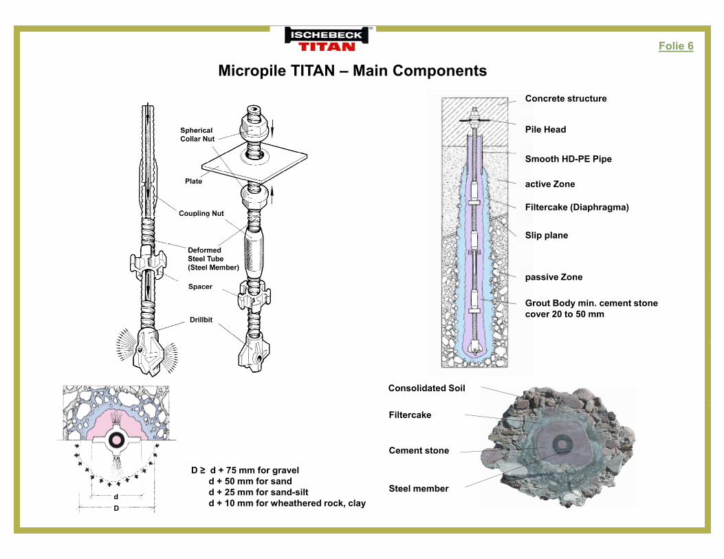
Micropile TITAN – Main ComponentsConcrete structure
Pile Head
Smooth HD-PE Pipe
active Zone
Filtercake (Diaphragma)
Slip plane
passive Zonepassive Zone
Grout Body min. cement stone cover 20 to 50 mm
Consolidated Soil
Filtercake
Cement stone
D ≥ d + 75 mm for gravel
Steel member
D ≥ d + 75 mm for gravel d + 50 mm for sandd + 25 mm for sand-siltd + 10 mm for wheathered rock, clay
dD
Folie 7
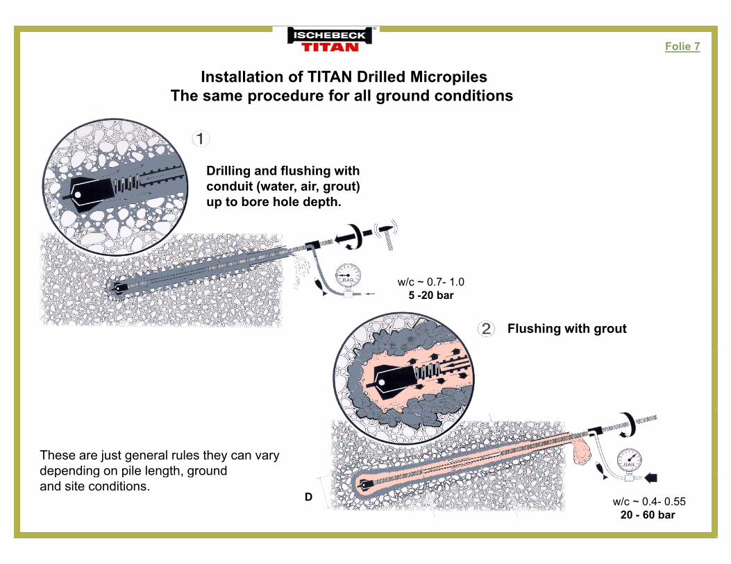
Installation of TITAN Drilled MicropilesTh d f ll d ditiThe same procedure for all ground conditions
Drilling and flushing with conduit (water, air, grout)up to bore hole depth.
w/c ~ 0 7 1 0w/c ~ 0.7- 1.0 5 -20 bar
Flushing with grout
These are just general rules they can vary depending on pile length, ground
w/c ~ 0.4- 0.5520 - 60 bar
depending on pile length, groundand site conditions.
D
Folie 8
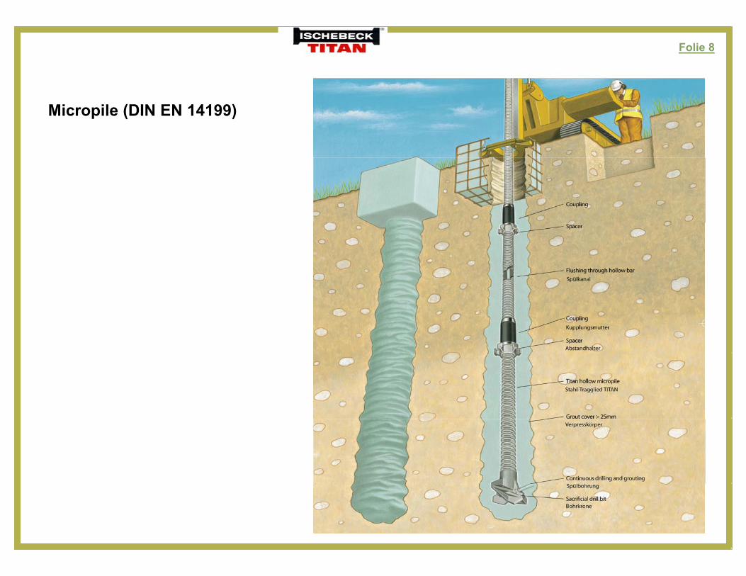
Micropile (DIN EN 14199)
Folie 9
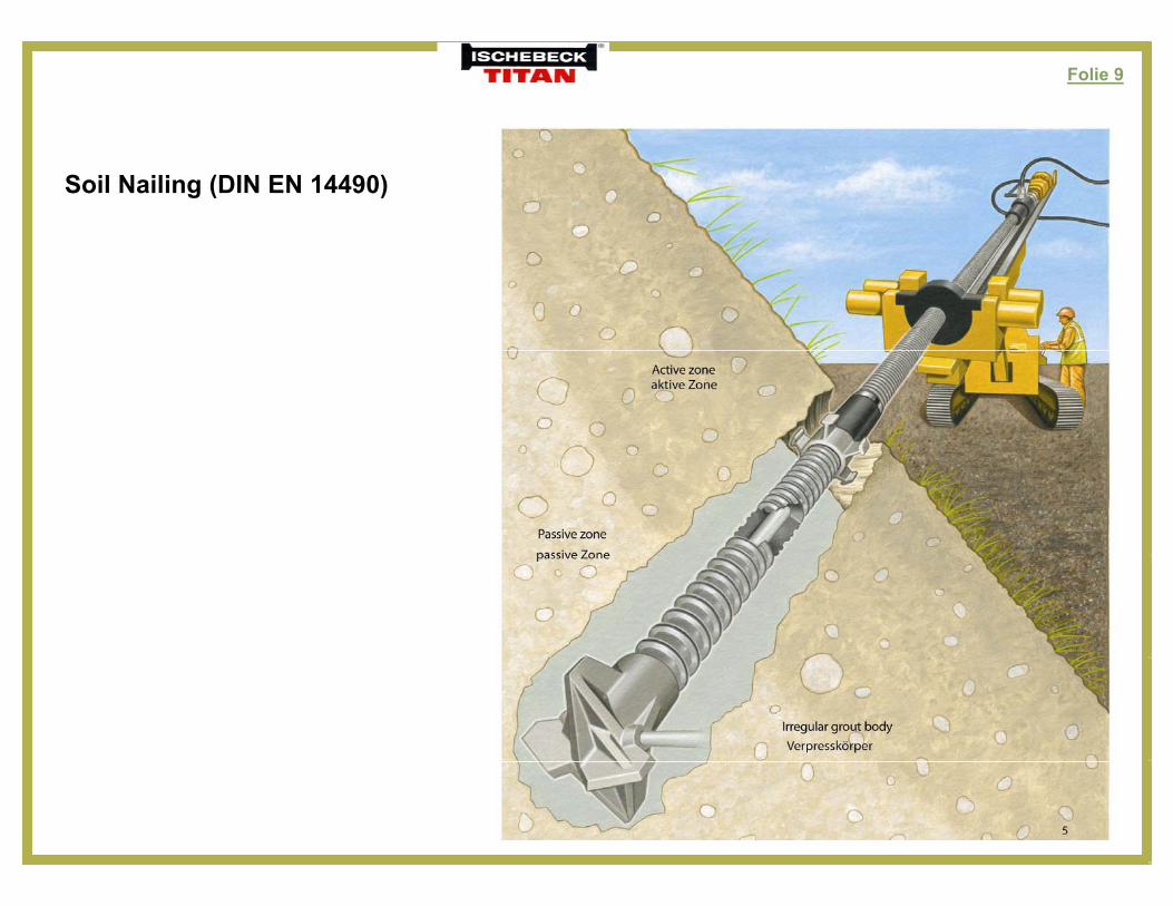
Soil Nailing (DIN EN 14490)
Folie 10
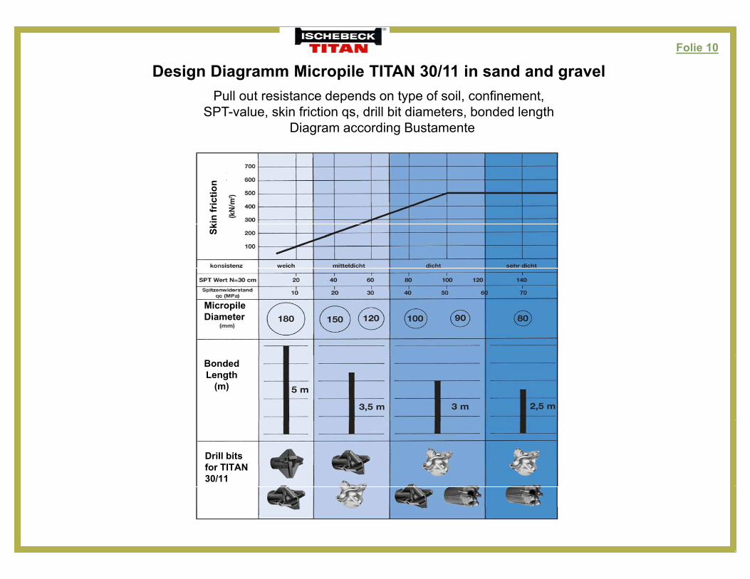
Design Diagramm Micropile TITAN 30/11 in sand and gravelP ll t i t d d t f il fi tPull out resistance depends on type of soil, confinement,
SPT-value, skin friction qs, drill bit diameters, bonded lengthDiagram according Bustamente
MicropileDiameter
BondedLength
(m)
Drill bitsfor TITAN 30/11
Folie 11
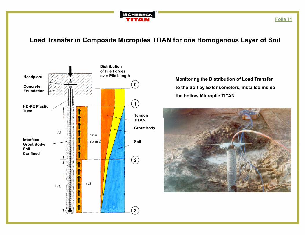
d T f i C i Mi il TITAN f H f S ilLoad Transfer in Composite Micropiles TITAN for one Homogenous Layer of Soil
Headplate
ConcreteFoundation
Distributionof Pile Forcesover Pile Length
0Monitoring the Distribution of Load Transfer
to the Soil by Extensometers, installed inside Foundation
HD-PE Plastic Tube
Tendon
1
the hollow Micropile TITAN
InterfaceGrout Body/
TITAN
Grout Body
Soilqs1=
2 x qs2Grout Body/SoilConfined
2
qs2
3
Folie 12
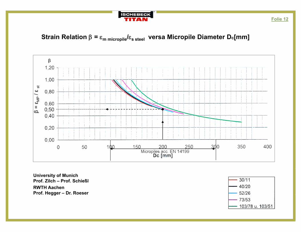
Strain Relation = / versa Micropile Diameter Dc[mm]Strain Relation = m micropile/s steel versa Micropile Diameter Dc[mm]
β
stβ
= ε M
P/ ε
University of MunichProf. Zilch – Prof. SchießlRWTH AachenProf. Hegger – Dr. Roesergg
Folie 13
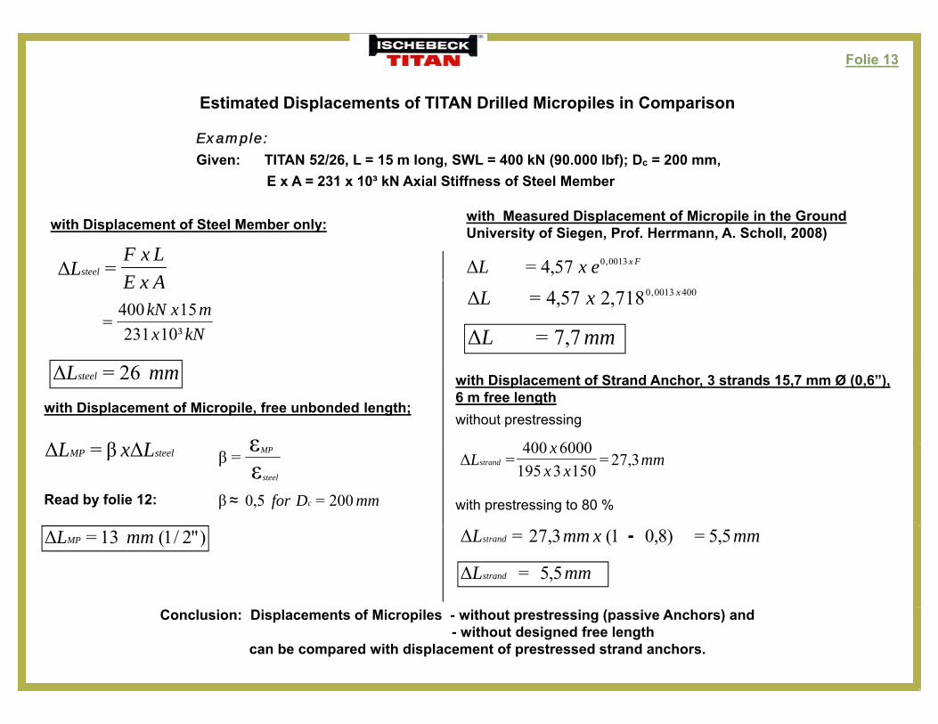
Estimated Displacements of TITAN Drilled Micropiles in Comparison
Example:
Given: TITAN 52/26, L = 15 m long, SWL = 400 kN (90.000 lbf); Dc = 200 mm, E x A = 231 x 10³ kN Axial Stiffness of Steel Member
with Displacement of Steel Member only:
AxELxF
Lsteel =Δ
with Measured Displacement of Micropile in the GroundUniversity of Siegen, Prof. Herrmann, A. Scholl, 2008)
FxexL 0013,057,4=ΔAxE
kNxmxkN
³1023115400
=
4000013,0718,257,4= xxLΔ
mmL 7,7=Δ
with Displacement of Micropile, free unbonded length;
mmLsteel 26=Δ
LL ΔβΔ ε
with Displacement of Strand Anchor, 3 strands 15,7 mm Ø (0,6”),6 m free lengthwithout prestressing
6000400
with prestressing to 80 %
steelMP LxL ΔβΔ =εε
βsteel
MP=
Read by folie 12: mmDfor c 200=5,0≈β
mmxx
xLstrand 3,27=
15031956000400
=Δ
)"2/1(13= mmLMPΔ 5,5=)8,01(3,27= mmxmmLstrandΔ
5,5= mmLstrandΔ
-
Conclusion: Displacements of Micropiles - without prestressing (passive Anchors) and- without designed free length
can be compared with displacement of prestressed strand anchors.
Folie 14
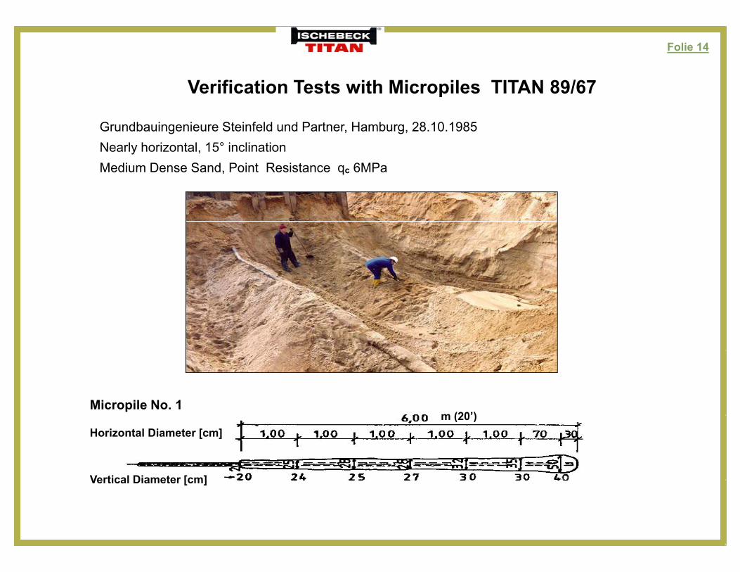
Verification Tests with Micropiles TITAN 89/67
Grundbauingenieure Steinfeld und Partner, Hamburg, 28.10.1985Nearly horizontal, 15° inclination
Verification Tests with Micropiles TITAN 89/67
Medium Dense Sand, Point Resistance qc 6MPa
Micropile No. 1m (20’)
Vertical Diameter [cm]
Horizontal Diameter [cm]m (20 )
Vertical Diameter [cm]
Folie 15
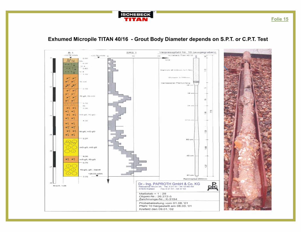
E h d Mi il TITAN 40/16 G B d Di d d S P T C P T TExhumed Micropile TITAN 40/16 - Grout Body Diameter depends on S.P.T. or C.P.T. Test
Folie 16
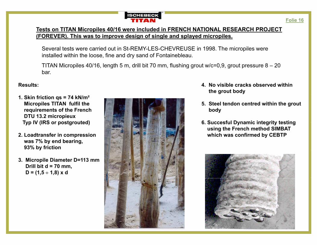
Tests on TITAN Micropiles 40/16 were included in FRENCH NATIONAL RESEARCH PROJECT (FOREVER). This was to improve design of single and splayed micropiles.
Several tests were carried out in St-REMY-LES-CHEVREUSE in 1998. The micropiles were installed within the loose, fine and dry sand of Fontainebleau.
TITAN Micropiles 40/16, length 5 m, drill bit 70 mm, flushing grout w/c=0,9, grout pressure 8 – 20
Results: 4. No visible cracks observed within the grout body
TITAN Micropiles 40/16, length 5 m, drill bit 70 mm, flushing grout w/c 0,9, grout pressure 8 20 bar.
1. Skin friction qs = 74 kN/m²Micropiles TITAN fulfil therequirements of the French DTU 13.2 micropieux
Typ IV (IRS or postgrouted)
5. Steel tendon centred within the groutbody
6 Succesful Dynamic integrity testingTyp IV (IRS or postgrouted)
2. Loadtransfer in compression was 7% by end bearing, 93% by friction
6. Succesful Dynamic integrity testing using the French method SIMBATwhich was confirmed by CEBTP
3. Micropile Diameter D=113 mmDrill bit d = 70 mm,D = (1,5 1,8) x d
Folie 17
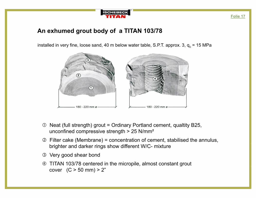
An exhumed grout body of a TITAN 103/78An exhumed grout body of a TITAN 103/78
installed in very fine, loose sand, 40 m below water table, S.P.T. approx. 3, qc = 15 MPa
Neat (full strength) grout = Ordinary Portland cement, qualtity B25,unconfined compressive strength > 25 N/mm²
Filter cake (Membrane) = concentration of cement, stabilised the annulus,brighter and darker rings show different W/C- mixture
Very good shear bond
TITAN 103/78 centered in the micropile, almost constant groutgcover (C > 50 mm) > 2”
Folie 18
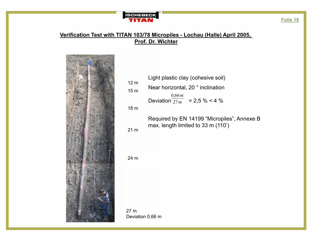
Verification Test with TITAN 103/78 Micropiles - Lochau (Halle) April 2005, Prof. Dr. Wichter
Light plastic clay (cohesive soil)
Near horizontal, 20 ° inclination15 m
12 m
Deviation = 2,5 % < 4 %
Required by EN 14199 “Micropiles”, Annexe B
mm
2766,0
18 m
q y p ,max. length limited to 33 m (110’)
21 m
24 m
27 mDeviation 0,66 m
Folie 19
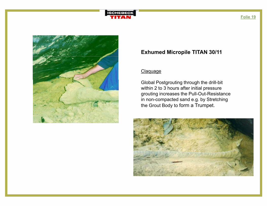
Exhumed Micropile TITAN 30/11
Claquage
Global Postgrouting through the drill-bit within 2 to 3 hours after initial pressuregrouting increases the Pull-Out-Resistancein non-compacted sand e.g. by Stretching the Grout Body to form a Trumpet.
Folie 20
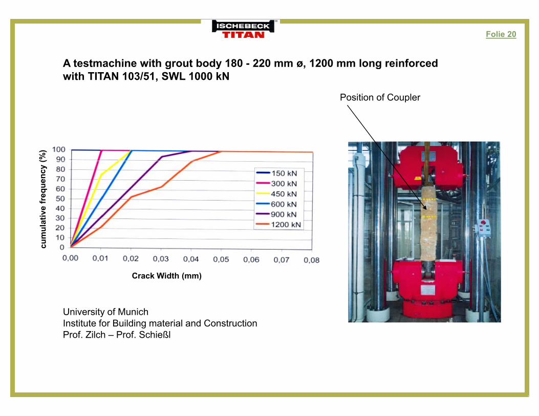
A testmachine with grout body 180 - 220 mm ø, 1200 mm long reinforcedA testmachine with grout body 180 220 mm ø, 1200 mm long reinforced with TITAN 103/51, SWL 1000 kN
Position of Coupler
Crack Width (mm)
University of MunichInstitute for Building material and ConstructionProf. Zilch – Prof. Schießl
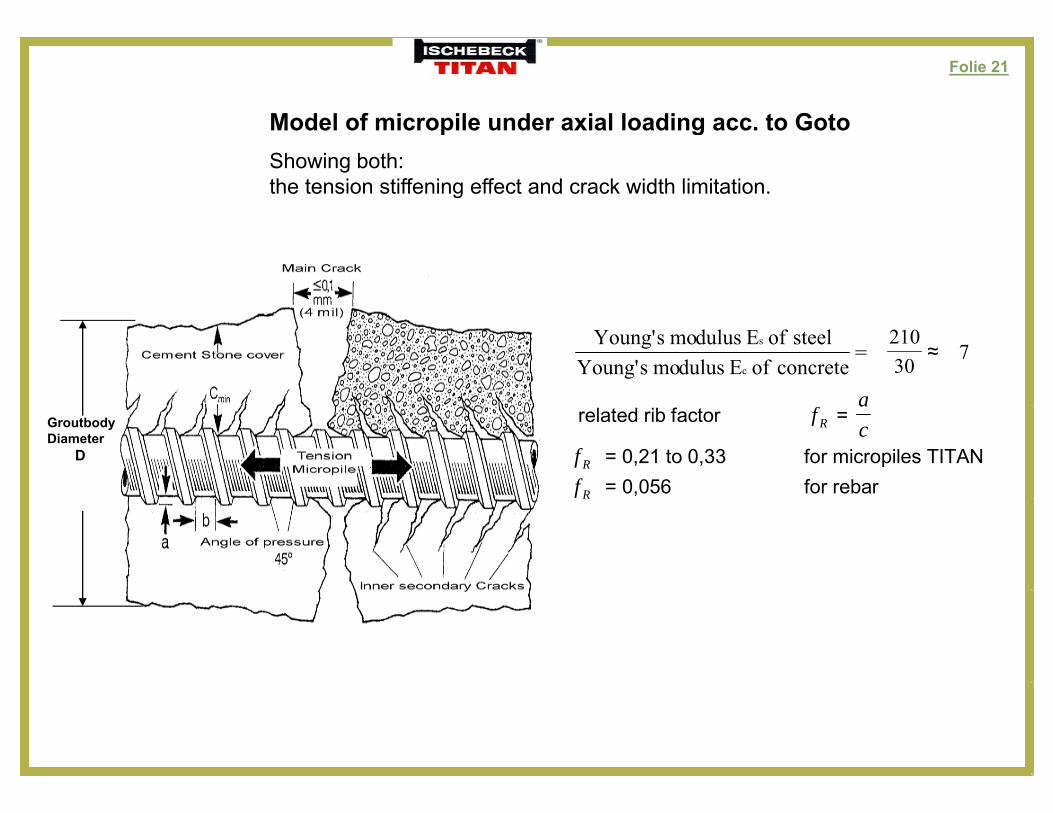
Folie 21
Model of micropile under axial loading acc. to GotoModel of micropile under axial loading acc. to GotoShowing both: the tension stiffening effect and crack width limitation.
a
=concreteofEdulusmosYoung'steelofEdulusmosYoung'
c
s7≈
30210
related rib factor Rf = c
Rf = 0,21 to 0,33 for micropiles TITAN Rf = 0,056 for rebar
GroutbodyDiameter
D
Folie 22
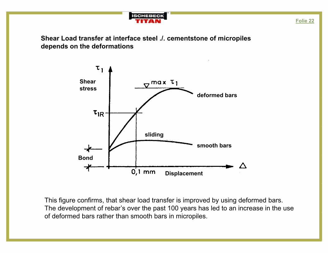
Shear Load transfer at interface steel ./. cementstone of micropilesShear Load transfer at interface steel ./. cementstone of micropiles depends on the deformations
deformed bars
Shearstress
smooth bars
sliding
Bond
Displacement
This figure confirms, that shear load transfer is improved by using deformed bars. The development of rebar’s over the past 100 years has led to an increase in the use of deformed bars rather than smooth bars in micropiles.
Folie 23
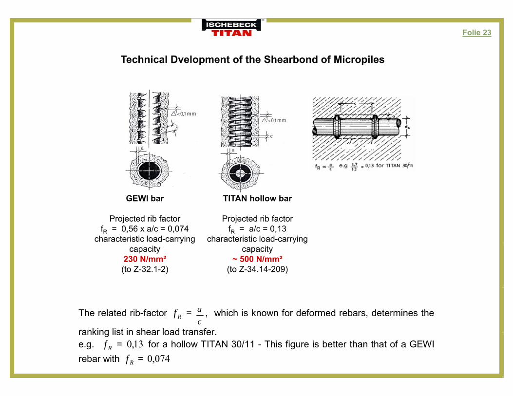
Technical Dvelopment of the Shearbond of Micropilesp p
GEWI bar TITAN hollow barGEWI bar
Projected rib factorfR = 0,56 x a/c = 0,074
characteristic load-carrying
TITAN hollow bar
Projected rib factorfR = a/c = 0,13
characteristic load-carrying y gcapacity
230 N/mm²(to Z-32.1-2)
y gcapacity
~ 500 N/mm²(to Z-34.14-209)
The related rib-factor Rf = ca , which is known for deformed rebars, determines the
ranking list in shear load transferranking list in shear load transfer.e.g. Rf = 13,0 for a hollow TITAN 30/11 - This figure is better than that of a GEWI rebar with Rf = 074,0
Folie 24
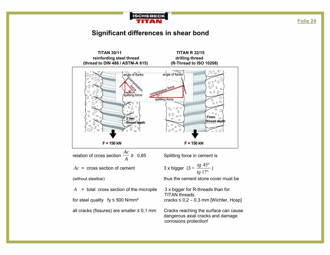
Significant differences in shear bond
TITAN 30/11 TITAN R 32/15reinfording steel thread drilling thread
(thread to DIN 488 / ASTM-A 615) (R-Thread to ISO 10208)
angle of flanks angle of flanks
45°17°splitting force
splitting forcecompression force
compressionforce
angle of flanks angle of flanks
45°17°splitting force
splitting forcecompression force
compressionforce
1 mmthread depth
2 mmthread depth
splitting force
1 mmthread depth
2 mmthread depth
splitting force
F = 150 kN F = 150 kNF = 150 kN F = 150 kN
relation of cross section ≥Ac
0 85 Splitting force in cement isrelation of cross section ≥A
0,85 Splitting force in cement is
Ac = cross section of cement 3 x bigger (3 ~
1745
tgtg
)
(without steelbar) thus the cement stone cover must be A = total cross section of the micropile 3 x bigger for R-threads than for TITAN threads. for steel quality fy ≤ 500 N/mm² cracks ≤ 0,2 – 0,3 mm [Wichter, Hosp] all cracks (fissures) are smaller ≤ 0,1 mm Cracks reaching the surface can cause
d i l k d d dangerous axial cracks and damage corrosions protection!
Folie 25
Conclusion:
R-thread does not comply with the requirements of international reinforcing steel standard (ASTM A 615 EN 10080 DIN 488)steel standard. (ASTM A 615, EN 10080, DIN 488)
Additional corrosion protection – e.g. galvanising, sacrificial losses –need to be consideredneed to be considered.
However galvanising of sacrificial losses are not allowed in Germany (DIBt) and some other countriessome other countries.
Therefore R-thread finds acceptance only for temporary tunnelling applications or less than 7 50 years life time depending on ground conditions [ETA 08/0277 MAI]less than 7 – 50 years life time, depending on ground conditions. [ETA-08/0277 MAI]
Folie 26
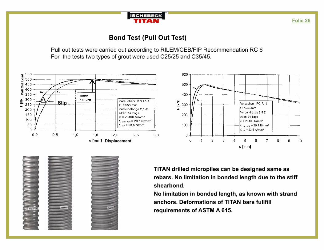
Bond Test (Pull Out Test)( )
Pull out tests were carried out according to RILEM/CEB/FIP Recommendation RC 6For the tests two types of grout were used C25/25 and C35/45.
Pull
Out
Loa
d
SlipΔ
Displacement
TITAN drilled micropiles can be designed same as rebars. No limitation in bonded length due to the stiff shearbond.No limitation in bonded length, as known with strand anchors. Deformations of TITAN bars fullfill requirements of ASTM A 615requirements of ASTM A 615.
Folie 27
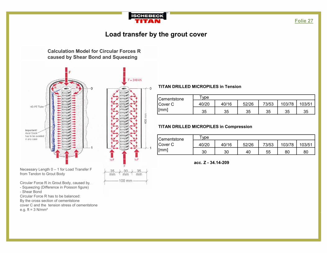
Load transfer by the grout cover
Calculation Model for Circular Forces R caused by Shear Bond and Squeezing
TITAN DRILLED MICROPILES in Tension
TypeC t t Type40/20 40/16 52/26 73/53 103/78 103/51
35 35 35 35 35 35
TITAN DRILLED MICROPILES in Compression
CementstoneCover C[mm]
TITAN DRILLED MICROPILES in Compression
Type
40/20 40/16 52/26 73/53 103/78 103/51
30 30 40 55 80 80
CementstoneCover C[mm]
acc. Z - 34.14-209Necessary Length 0 – 1 for Load Transfer Ffrom Tendon to Grout Body
Circular Force R in Grout Body, caused byCircular Force R in Grout Body, caused by- Squeezing (Difference in Poisson figure)- Shear BondCircular Force R has to be balanced:By the cross section of cementstone cover C and the tension stress of cementstone e.g. ft = 3 N/mm²
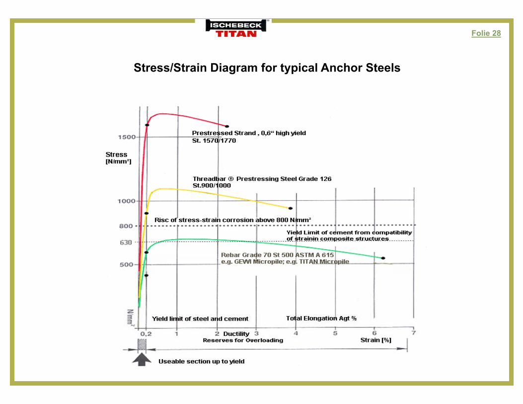
Folie 28
St /St i Di f t i l A h St lStress/Strain Diagram for typical Anchor Steels

Folie 29
Stress/Strain Diagram with Bauschinger EffectStress/Strain Diagram with Bauschinger Effect
A typical stress strain diagram of cold formed steel
Ductility Bauschinger Effect
R d ti f i ld b B hi Eff t
A typical stress-strain diagram of cold formed steel
tendons shows the Bauschinger Effect.Bauschinger Effect means, that the stress–strain
graph line is curved, not linear as it should be, Reduction of yield by Bauschinger Effect according to Hooke and therefore the yield stress
is reduced.
min.
0,2

Folie 30
Fatigue (Wöhler-Diagram) of coupled steel-tendons under cyclic loading,such as changing from compression to tension.Fatigue by cyclic loading is reduced using a TITAN micropile with a coupler without counter nuts.The coupler is double locked by a self locking thread (friction angle < tg 6°) and additionalPrestressed by the torque of the drill hammer during connection.Prestressed by the torque of the drill hammer during connection.
Load-Displacement-Curves for a Coupler TITAN 103/78
Loading with ± 1000 kN within 3 seconds of changing fromcompression to tensioncompression to tension.
Fatigue Test: Coupled TITAN 103/78
Folie 31
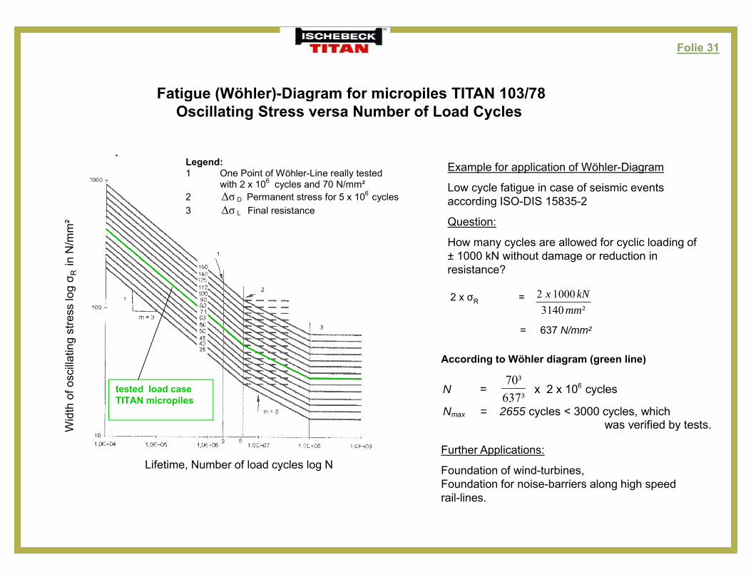
Fatigue (Wöhler) Diagram for micropiles TITAN 103/78Fatigue (Wöhler)-Diagram for micropiles TITAN 103/78Oscillating Stress versa Number of Load Cycles
.L dLegend: 1 One Point of Wöhler-Line really tested
with 2 x 10⁶ cycles and 70 N/mm² 2 σΔ D Permanent stress for 5 x 10⁶ cycles 3 σΔ L Final resistance
Example for application of Wöhler-Diagram
Low cycle fatigue in case of seismic events according ISO-DIS 15835-2
Question:m² Question:
How many cycles are allowed for cyclic loading of ± 1000 kN without damage or reduction in resistance?
10002 kNg σ R
in N
/mm
2 x σR =²3140
10002mm
kNx
= 637 N/mm²
A di t Wöhl di ( li )ting
stre
ss lo
g
tested load caseTITAN micropiles
According to Wöhler diagram (green line)
N = ³637³70
x 2 x 106 cycles
Nmax = 2655 cycles < 3000 cycles, which ifi d b t tW
idth
of o
scilla
Lifetime, Number of load cycles log N
was verified by tests.
Further Applications:
Foundation of wind-turbines,Foundation for noise-barriers along high speed
W
Foundation for noise barriers along high speedrail-lines.
Folie 32
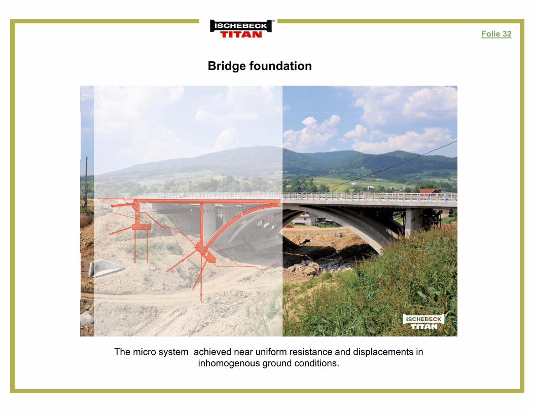
Bridge foundationBridge foundation
The micro system achieved near uniform resistance and displacements in inhomogenous ground conditions.
Folie 33
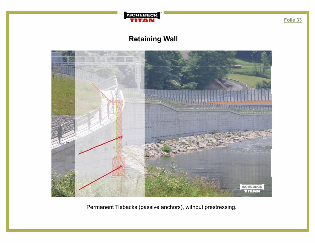
Retaining WallRetaining Wall
Permanent Tiebacks (passive anchors), without prestressing.
Folie 34
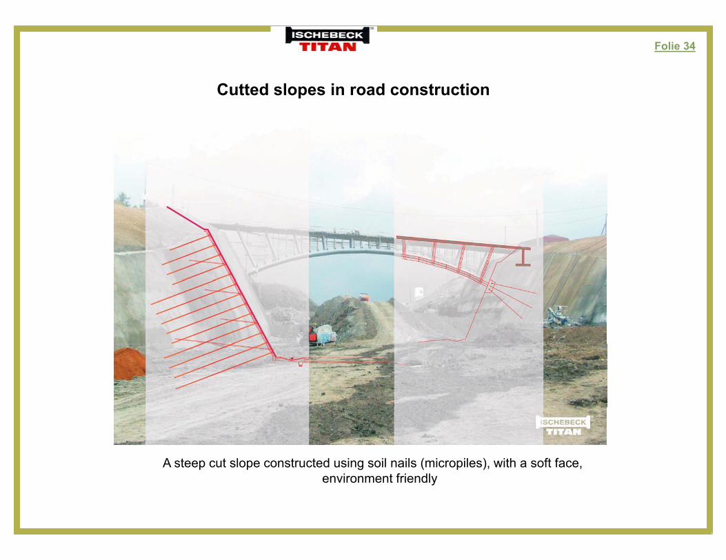
Cutted slopes in road constructionCutted slopes in road construction
A steep cut slope constructed using soil nails (micropiles), with a soft face,environment friendly
Folie 35
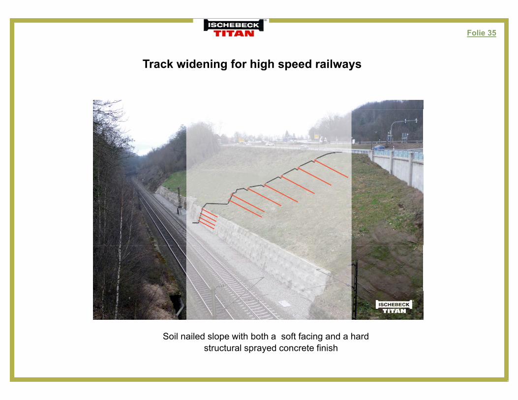
Track widening for high speed railwaysTrack widening for high speed railways
Soil nailed slope with both a soft facing and a hardSoil nailed slope with both a soft facing and a hard structural sprayed concrete finish
Folie 36
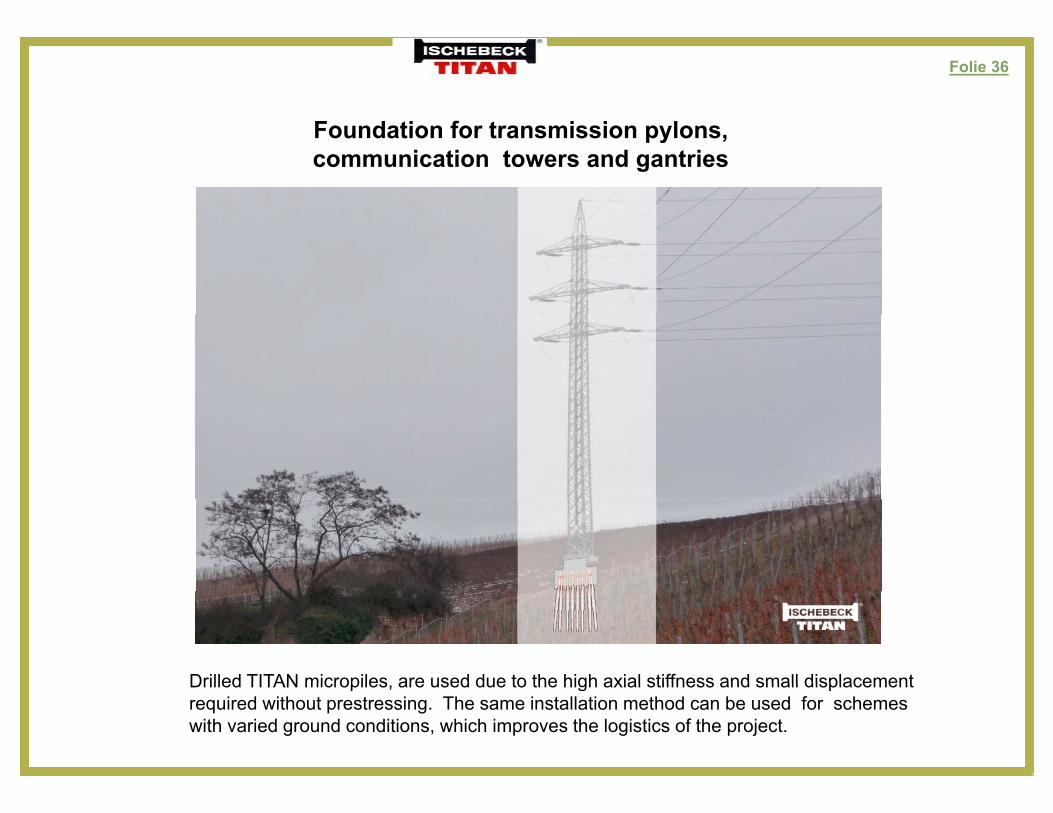
Foundation for transmission pylonsFoundation for transmission pylons, communication towers and gantries
Drilled TITAN micropiles are used due to the high axial stiffness and small displacementDrilled TITAN micropiles, are used due to the high axial stiffness and small displacementrequired without prestressing. The same installation method can be used for schemes with varied ground conditions, which improves the logistics of the project.
Folie 37
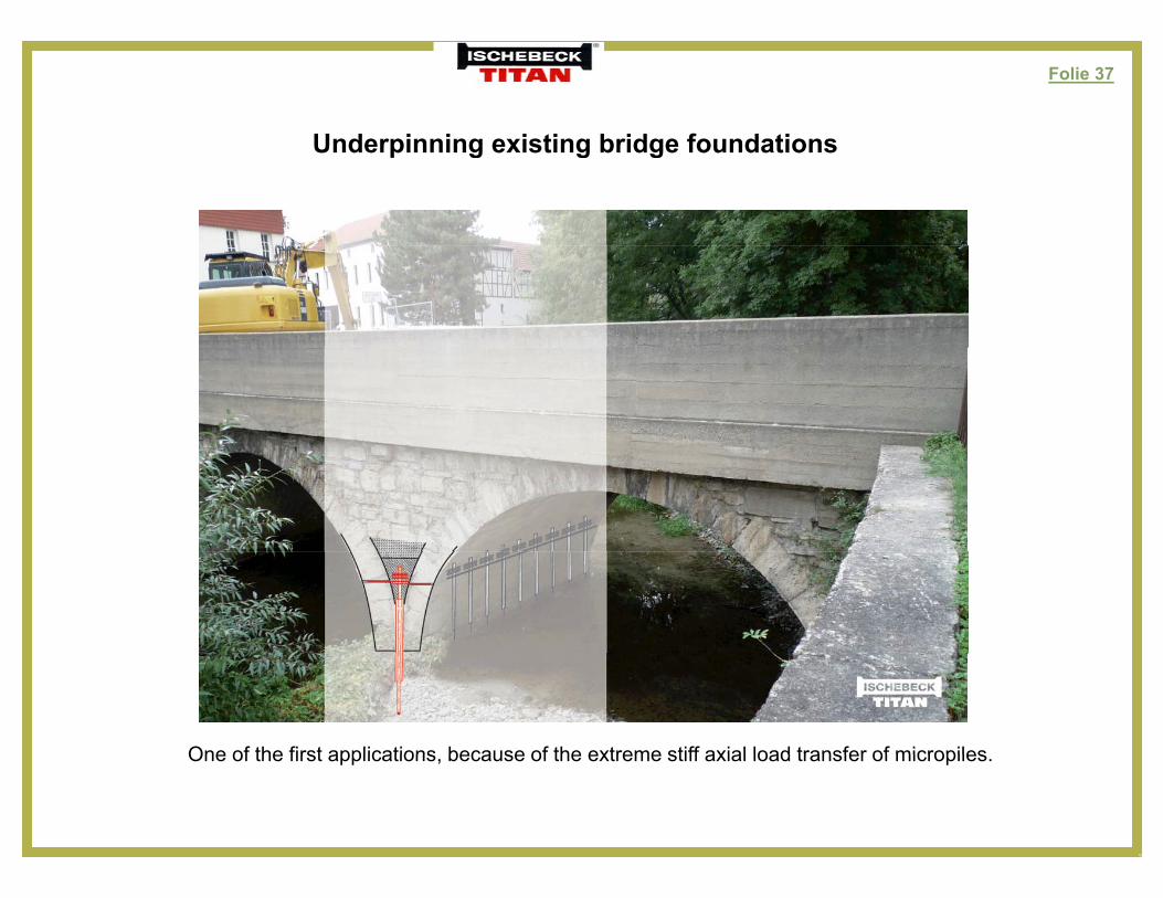
Underpinning existing bridge foundationsUnderpinning existing bridge foundations
One of the first applications because of the extreme stiff axial load transfer of micropilesOne of the first applications, because of the extreme stiff axial load transfer of micropiles.
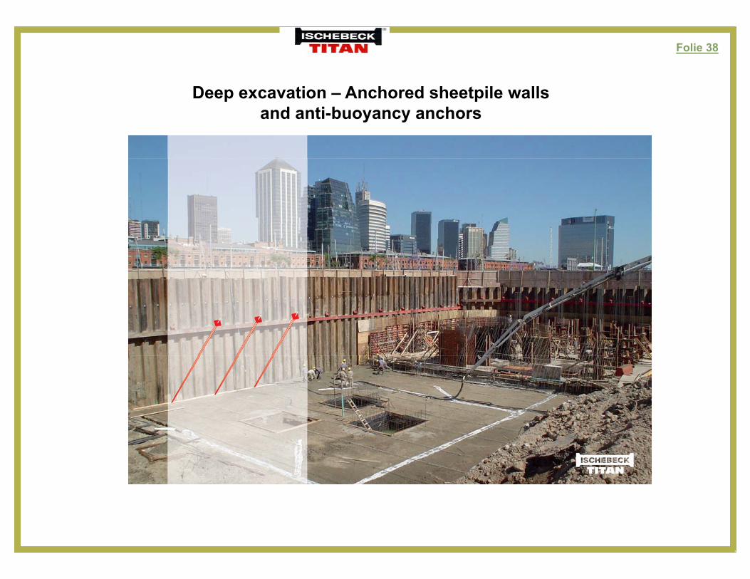
Folie 38
Deep excavation Anchored sheetpile wallsDeep excavation – Anchored sheetpile walls and anti-buoyancy anchors
Folie 39
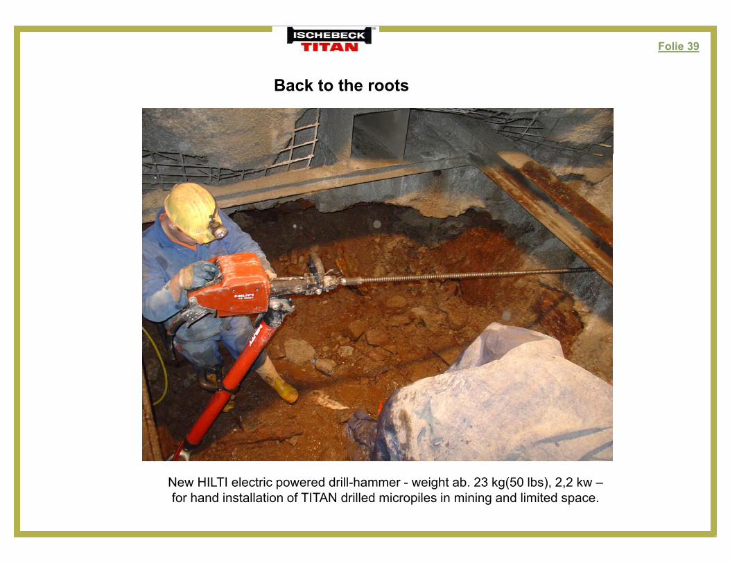
Back to the rootsBack to the roots
New HILTI electric powered drill-hammer - weight ab. 23 kg(50 lbs), 2,2 kw –for hand installation of TITAN drilled micropiles in mining and limited space.

Folie 40