fridley, k.j. timber structures structural engineering ...freeit.free.fr/structure engineering...
TRANSCRIPT

Fridley, K.J. “Timber Structures”Structural Engineering HandbookEd. Chen Wai-FahBoca Raton: CRC Press LLC, 1999
Timber Structures
Kenneth J. FridleyDepartment of Civil &Environmental Engineering,Washington State University,Pullman, WA
9.1 IntroductionTypes of Wood Products • Types of Structures • Design Spec-ifications and Industry Resources
9.2 Properties of Wood9.3 Preliminary Design Considerations
Loads and Load Combinations • Design Values • Adjustmentof Design Values
9.4 Beam DesignMoment Capacity • Shear Capacity • Bearing Capacity • NDS®Provisions
9.5 Tension Member Design9.6 Column Design
Solid Columns • Spaced Columns • Built-Up Columns • NDS®Provisions
9.7 Combined Load DesignCombined Bending and Axial Tension • Biaxial Bending orCombined Bending and Axial Compression • NDS® Provi-sions
9.8 Fastener and Connection DesignNails, Spikes, and Screws • Bolts, Lag Screws, and Dowels •Other Types of Connections • NDS® Provisions
9.9 Structural PanelsPanel Section Properties • Panel Design Values • Design Re-sources
9.10 Shear Walls and DiaphragmsRequired Resistance • Shear Wall and Diaphragm Resistance •Design Resources
9.11 Trusses9.12 Curved Beams and Arches
Curved Beams • Arches • Design Resources
9.13 Serviceability ConsiderationsDeflections • Vibrations • NDS® Provisions • Non-StructuralPerformance
9.14 Defining TermsReferencesFurther Reading
9.1 Introduction
Wood is one of the earliest building materials, and as such its use often has been based more ontradition than principles of engineering. However, the structural use of wood and wood-based
c©1999 by CRC Press LLC
materials has increased steadily in recent times. The driving force behind this increase in use is theever-increasing need to provide economical housing for the world’s population. Supporting thisneed, though, has been an evolution of our understanding of wood as a structural material andability to analyze and design safe and functional timber structures. This evolution is evidenced by therecent industry-sponsored development of the Load and Resistance Factor Design (LRFD) Standardfor Engineered Wood Construction [1, 5].
An accurate and complete understanding of any material is key to its proper use in structural appli-cations, and structural timber and other wood-based materials are no exception to this requirement.This section introduces the fundamental mechanical and physical properties of wood that govern itsstructural use, then presents fundamental considerations for the design of timber structures. Thebasics of beam, column, connection, and structural panel design are presented. Then, issues relatedto shear wall and diaphragm, truss, and arch design are presented. The section concludes with adiscussion of current serviceability design code provisions and other serviceability considerationsrelevant to the design of timber structures. The use of the new LRFD provisions for timber struc-tures [1, 5] is emphasized in this section; however, reference is also made to existing allowable stressprovisions [2] due to their current popular use.
9.1.1 Types of Wood Products
There are a wide variety of wood and wood-based structural building products available for use inmost types of structures. The most common products include solid lumber, glued laminated timber,plywood, andorientated strandboard (OSB). Solid sawn lumberwas themainstayof timber construc-tion and is still used extensively; however, the changing resource base and shift to plantation-growntrees has limited the size and quality of the raw material. Therefore, it is becoming increasinglydifficult to obtain high quality, large dimension timbers for construction. This change in raw ma-terial, along with a demand for stronger and more cost effective material, initiated the developmentof alternative products that can replace solid lumber. Engineered products such as wood compositeI-joists and structural composite lumber (SCL) were the result of this evolution. These products havesteadily gained popularity and now are receiving wide-spread use in construction.
9.1.2 Types of Structures
By far, the dominate types of structures utilizing wood and wood-based materials are residential andlight commercial buildings. There are, however, numerous examples available of larger wood struc-tures, such as gymnasiums, domes, and multistory office buildings. Light-frame construction is themost common type used for residential structures. Light-frame consists of nominal “2-by” lumbersuch as 2 × 4s (38 mm × 89 mm) up to 2 × 12s (38 mm × 286 mm) as the primary framing elements.Post-and-beam (or timber-frame) construction is perhaps the oldest type of timber structure, and hasreceived renewed attention in specialty markets in recent years. Prefabricated panelized constructionhas also gained popularity in recent times. Reduced cost and shorter construction time have beenthe primary reasons for the interest in panelized construction. Both framed (similar to light-frameconstruction) and insulated (where the core is filled with a rigid insulating foam) panels are used.Other types of construction include glued-laminated construction (typically for longer spans), polebuildings (typical in so-called “agricultural” buildings, but making entry into commercial applica-tions as well), and shell and folded plate systems (common for gymnasiums and other larger enclosedareas). The use of wood and wood-based products as only a part of a complete structural systemis also quite common. For example, wood roof systems supported by masonry walls or wood floorsystems supported by steel frames are common in larger projects.
Wood and wood-based products are not limited to building structures, but are also used in trans-portation structures as well. Timber bridges are not new, as evidenced by the number of covered
c©1999 by CRC Press LLC
bridges throughout the U.S. Recently, however, modern timber bridges have received renewed atten-tion, especially for short-span, low-volume crossings.
9.1.3 Design Specifications and Industry Resources
The National Design Specification for Wood Construction, or NDS® [2], is currently the primarydesign specification for engineered wood construction. The NDS® is an allowable stress design(ASD) specification. As with the other major design specifications in the U.S., a Load and ResistanceFactor Design (LRFD) Standard for Engineered Wood Construction [1, 5] has been developed andis recognized by all model building codes as an alternate to the NDS® . In this section, the LRFDapproach to timber design will be emphasized; however, ASD requirements as provided by theNDS®, as well as other wood design specifications, also will be presented due to its current popularityand acceptance. Additionally, most provisions in the NDS® are quite similar to those in the LRFDexcept that the NDS® casts design requirements in terms of allowable stresses and loads and the LRFDutilizes nominal strength values and factored load combinations.
In addition to the NDS® and LRFD Standard, other design manuals, guidelines, and specificationsare available. For example, the Timber Construction Manual [3] provides information related toengineered wood construction in general and glued laminated timber in more detail, and the PlywoodDesignSpecification (PDS®)[6] and its supplementspresent information related toplywoodpropertiesanddesignof variouspanel-based structural systems. Additionally, various industry associations suchas the APA–The Engineered Wood Association, American Institute of Timber Construction (AITC),American Forest & Paper Association–American Wood Council (AF&PA – AWC), Canadian WoodCouncil (CWC), Southern Forest Products Association (SFPA), Western Wood Products Association(WWPA), and Wood Truss Council of America (WTCA), to name but a few, provide extensivetechnical information.
One strength of the LRFD Specification is its comprehensive coverage of engineered wood con-struction. While the NDS® governs the design of solid-sawn members and connections, the TimberConstruction Manual primarily provides procedures for the design of glued-laminated members andconnections, and the PDS® addresses the design of plywood and other panel-based systems, the LRFDis complete in that it combines information from these and other sources to provide the engineer acomprehensive design specification, including design procedures for lumber, connections, I-joists,metal plate connected trusses, glued laminated timber, SCL, wood-base panels, timber poles andpiles, etc. To be even more complete, the AF&PA has developed the Manual of Wood Construction:Load & Resistance Factor Design [1]. The Manual includes design value supplements, guidelines todesign, and the formal LRFD Specification [5].
9.2 Properties of Wood
It is important to understand the basic structure of wood in order to avoid many of the pitfallsrelative to the misuse and/or misapplication of the material. Wood is a natural, cellular, anisotropic,hyrgothermal, and viscoelastic material, and by its natural origins contains a multitude of inclusionsand other defects.1 The reader is referred to any number of basic texts that present a description of
1The term “defect” may be misleading. Knots, grain characteristics (e.g., slope of grain, spiral grain, etc.), and othernaturally occurring irregularities do reduce the effective strength of the member, but are accounted for in the gradingprocess and in the assignment of design values. On the other hand, splits, checks, dimensional warping, etc. are the resultof the drying process and, although they are accounted for in the grading process, may occur after grading and may bemore accurately termed “defects”.
c©1999 by CRC Press LLC
the fundamental structure and physical properties of wood as a material (e.g., [8, 11, 20]).One aspect of wood that deserves attention here, however, is the affect of moisture on the physical
and mechanical properties and performance of wood. Many problems encountered with woodstructures can be traced to moisture. The amount of moisture present in wood is described bythe moisture content (MC), which is defined by the weight of the water contained in the wood as apercentage of the weight of the oven-dry wood. As wood is dried, water is first evaporated from thecell cavities. Then, as drying continues, water from the cell walls is drawn out. The moisture contentat which free water in the cell cavities is completely evaporated, but the cell walls are still saturated,is termed the fiber saturation point (FSP). The FSP is quite variable among and within species, butis on the order of 24 to 34%. The FSP is an important quantity since most physical and mechanicalproperties are dependent on changes in MC below the FSP, and the MC of wood in typical structuralapplications isbelowtheFSP.Finally, woodreleases andabsorbsmoisture toand fromthe surroundingenvironment. When the wood equilibrates with the environment and moisture is not transferring toor from the material, the wood is said to have reached its equilibrium moisture content (EMC). Tablesare available (see [20]) that provide the EMC for most species as a function of dry-bulb temperatureand relative humidity. These tables allow designers to estimate in-service moisture contents that arerequired for their design calculations.
In structural applications, wood is typically dried to a MC near that expected in service prior todimensioning and use. A major reason for this is that wood shrinks as its MC drops below the FSP.Wood machined to a specified size at a MC higher than that expected in service will therefore shrinkto a smaller size in use. Since the amount any particular piece of wood will shrink is difficult topredict, it would be very difficult to control dimensions of wood if it was not machined after it wasdried. Estimates of dimensional changes can be made with the use of published values of shrinkagecoefficients for various species (see [20]).
In addition to simple linear dimensional changes in wood, drying of wood can cause warp ofvarious types. Bow (distortion in the weak direction), crook (distortion in the strong direction),twist (rotational distortion), and cup (cross-sectional distortion similar to bow) are common formsof warp and, when excessive, can adversely affect the structural use of the member. Finally, dryingstresses (internal stress resulting from differential shrinkage) can be quite significant and lead tochecking (cracks formed along the growth rings) and splitting (cracks formed across the growthrings).
The mechanical properties of wood also are functions of the MC. Above the FSP, most propertiesare invariant with changes in MC, but most properties are highly affected by changes in the MC belowthe FPS. For example, the modulus of rupture of wood increases by nearly 4% for a 1% decrease inmoisture content below the FSP. For structural design purposes, design values are typically providedfor a specific maximum MC (e.g., 19%).
Load history can also have a significant effect on the mechanical performance of wood members.The load that causes failure is a function of the duration and/or rate the load is applied to the member;that is, a member can resist higher magnitude loads for shorter durations or, stated differently, thelonger a load is applied, the less able a wood member is to support that load. This response is termed“load duration” effects in wood design. Figure 9.1 illustrates this effect by plotting the time-to-failureas a function of the applied stress expressed in terms of the short term (static) strength. There aremany theoretical models proposed to represent this response, but the line shown in Figure 9.1 wasdeveloped at the U.S. Forest Products Laboratory in the early 1950s [20] and is the basis for designprovisions (i.e., design adjustment factors) in both the LRFD and NDS®.
The design factors derived from the relationship illustrated in Figure 9.1 are appropriate only forstresses and not for stiffness or, more precisely, the modulus of elasticity. Very much related to loadduration effects, the deflection of a wood member under sustained load increases over time. Thisresponse, termed creep effect, must be considered in design when deflections are critical from eithera safety or serviceability standpoint. The main parameters that significantly affect the creep response
c©1999 by CRC Press LLC
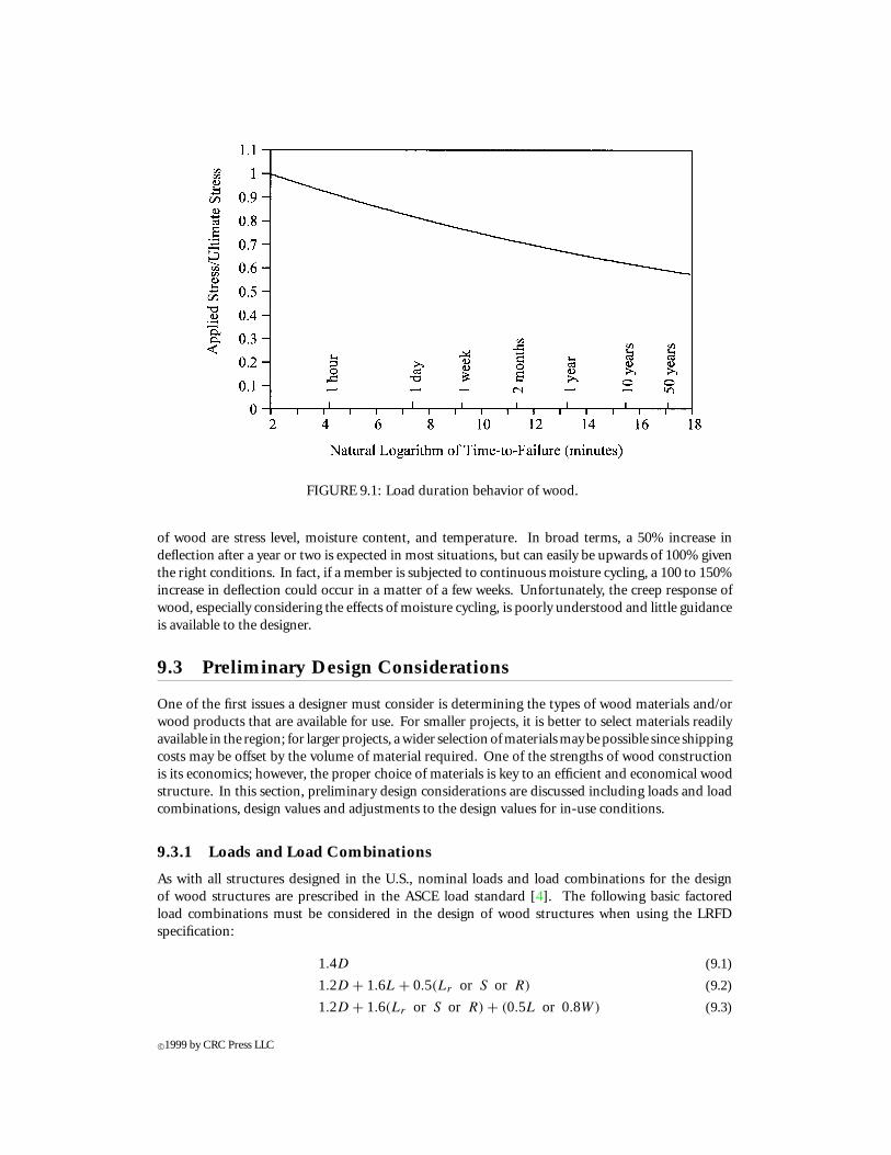
FIGURE 9.1: Load duration behavior of wood.
of wood are stress level, moisture content, and temperature. In broad terms, a 50% increase indeflection after a year or two is expected in most situations, but can easily be upwards of 100% giventhe right conditions. In fact, if a member is subjected to continuous moisture cycling, a 100 to 150%increase in deflection could occur in a matter of a few weeks. Unfortunately, the creep response ofwood, especially considering the effects of moisture cycling, is poorly understood and little guidanceis available to the designer.
9.3 Preliminary Design Considerations
One of the first issues a designer must consider is determining the types of wood materials and/orwood products that are available for use. For smaller projects, it is better to select materials readilyavailable in the region; for larger projects, a wider selection of materials may be possible since shippingcosts may be offset by the volume of material required. One of the strengths of wood constructionis its economics; however, the proper choice of materials is key to an efficient and economical woodstructure. In this section, preliminary design considerations are discussed including loads and loadcombinations, design values and adjustments to the design values for in-use conditions.
9.3.1 Loads and Load Combinations
As with all structures designed in the U.S., nominal loads and load combinations for the designof wood structures are prescribed in the ASCE load standard [4]. The following basic factoredload combinations must be considered in the design of wood structures when using the LRFDspecification:
1.4D (9.1)
1.2D + 1.6L + 0.5(Lr or S or R) (9.2)
1.2D + 1.6(Lr or S or R) + (0.5L or 0.8W) (9.3)
c©1999 by CRC Press LLC
1.2D + 1.3W + 0.5L + 0.5(Lr or S or R) (9.4)
1.2D + 1.0E + 0.5L + 0.2S (9.5)
0.9D − (1.3W or 1.0E) (9.6)
whereD = dead loadL = live load excluding environmental loads such as snow and windLr = roof live load during maintenanceS = snow loadR = rain or ice load excluding pondingW = wind loadE = earthquake load (determined in accordance in with [4])
For ASD, the ASCE load standard provides four load combinations that must be considered:D, D + L + (Lr or S or R), D + (W or E), and D + L + (Lr or S or R) + (W or E).
9.3.2 Design Values
The AF&PA [1] Manual of Wood Construction: Load and Resistance Factor Design provides nominaldesign values for visually and mechanically graded lumber, glued laminated timber, and connections.These values include reference bending strength, Fb; reference tensile strength parallel to the grain,Ft ; reference shear strength parallel to the grain, Fv ; reference compressive strength parallel andperpendicular to the grain, Fc and Fc⊥, respectively; reference bearing strength parallel to the grain,Fg ; and reference modulus of elasticity, E; and are appropriate for use with the LRFD provisions.In addition, the Manual provides design values for metal plate connections and trusses, structuralcomposite lumber, structural panels, and other pre-engineered structural wood products. (It shouldbe noted that the LRFD Specification [5] provides only the design provisions, and design values foruse with the LRFD Specification are provided in the AF&PA Manual.)
Similarly, the Supplement to the NDS® [2] provides tables of design values for visually gradedand machine stress rated lumber and glued laminated timber. The basic quantities are the same aswith the LRFD, but are in the form of allowable stresses and are appropriate for use with the ASDprovisions of the NDS®. Additionally, the NDS® provides tabulated allowable design values for manytypes of mechanical connections. Allowable design values for many proprietary products (e.g., SCL,I-joist, etc.) are provided by producers in accordance with established standards. For structuralpanels, design values are provided in the PDS® [6] and by individual product producers.
One main difference between the NDS® and LRFD design values, other than the NDS® prescribingallowable stresses and the LRFD prescribing nominal strengths, is the treatment of duration of loadeffects. Allowable stresses (except compression perpendicular to the grain) are tabulated in the NDS®and elsewhere for an assumed 10-year load duration in recognition of the duration of load effectdiscussed previously. The allowable compressive stress perpendicular to the grain is not adjustedsince a deformation definition of failure is used for this mode rather than fracture as in all othermodes; thus, the adjustment has been assumed unnecessary. Similarly, the modulus of elasticity isnot adjusted to a 10-year duration since the adjustment is defined for strength, not stiffness. For theLRFD, short-term (i.e., 20 min) nominal strengths are tabulated for all strength values. In the LRFD,design strengths are reduced for longer duration design loads based on the load combination beingconsidered. Conversely, in the NDS®, allowable stresses are increased for shorter load durations anddecreased only for permanent (i.e., greater than 10 years) loading.
9.3.3 Adjustment of Design Values
c©1999 by CRC Press LLC
In addition to providing reference design values, both the LRFD and the NDS® specifications pro-vide adjustment factors to determine final adjusted design values. Factors to be considered includeload duration (termed “time effect” in the LRFD), wet service, temperature, stability, size, volume,repetitive use, curvature, orientation (form), and bearing area. Each of these factors will be discussedfurther; however, it is important to note not all factors are applicable to all design values, and thedesigner must take care to properly apply the appropriate factors.
LRFDreference strengthsandNDS®allowable stressesarebasedonthe followingspecifiedreferenceconditions: (1) dry use in which the maximum EMC does not exceed 19% for solid wood and 16%for glued wood products; (2) continuous temperatures up to 32◦C, occasional temperatures up to65◦C (or briefly exceeding 93◦C for structural-use panels); (3) untreated (except for poles and piles);(4) new material, not reused or recycled material; and (5) single members without load sharing orcomposite action. To adjust the reference design value for other conditions, adjustment factors areprovided which are applied to the published reference design value:
R′ = R · C1 · C2 · · ·Cn (9.7)
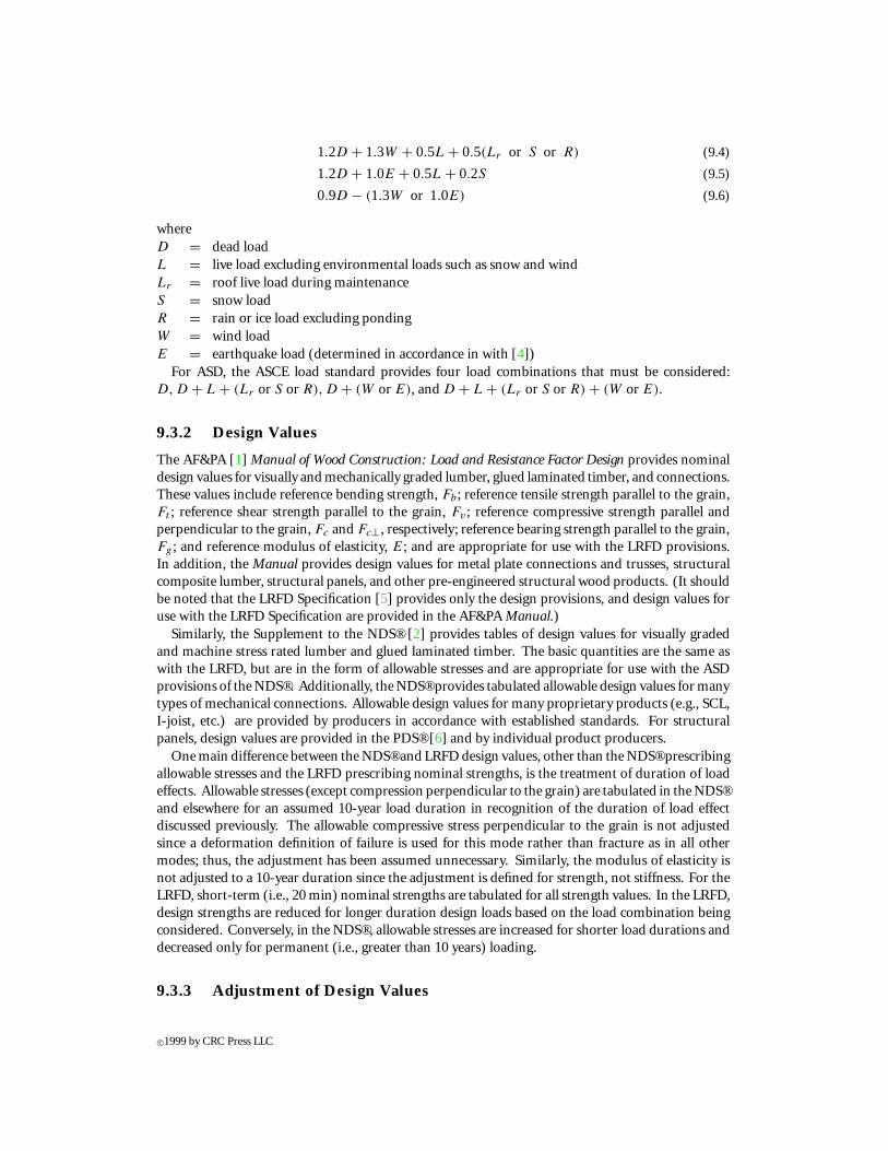
where R′ = adjusted design value (resistance), R = reference design value, and C1, C2, . . . Cn =applicable adjustment factors. Adjustment factors, for the most part, are common between theLRFD and the NDS®. Many factors are functions of the type, grade, and/or species of material whileother factors are common across the broad spectrum of materials. For solid sawn lumber, gluedlaminated timber, piles, and connections, adjustment factors are provided in the NDS® and the LRFDManual. For other products, especially proprietary products, the adjustment factors are providedby the product producers. The LRFD and NDS® list numerous factors to be considered, includingwet service, temperature, preservative treatment, fire-retardant treatment, composite action, loadsharing (repetitive-use), size, beam stability, column stability, bearing area, form (i.e., shape), timeeffect (load duration), etc. Many of these factors will be discussed as they pertain to specific designs;however, some of the factors are unique for specific applications and will not be discussed further.The four factors that are applied across the board to all design properties are the wet service factor,CM ; temperature factor, Ct ; preservative treatment factor, Cpt ; and fire-retardant treatment factor,Crt . The two treatment factors are provided by the individual treaters, but the wet service andtemperature factors are provided in the LRFD Manual. For example, when considering the designof solid sawn lumber members, the adjustment values given in Table 9.1 for wet service, which isdefined as the maximum EMC exceeding 19%, and Table 9.2 for temperature, which is applicablewhen continuous temperatures exceed 32◦C, are applicable to all design values.
TABLE 9.1 Wet Service Adjustment Factors, CM
Size adjustedaFb Size adjustedaFc
Thickness ≤ 20 MPa > 20 MPa Ft ≤ 12.4 MPa >12.4 MPa Fv Fc⊥ E, E05
≤ 90 mm 1.00 0.85 1.00 1.00 0.80 0.97 0.67 0.90> 90 mm 1.00 1.00 1.00 0.91 0.91 1.00 0.67 1.00
a Reference value adjusted for size only.
Since, as discussed, the LRFD and the NDS® handle time (duration of load) effects so differentlyand since duration of load effects are somewhat unique to wood design, it is appropriate to elaborateon it here. Whether using the NDS® or LRFD, a wood structure is designed to resist all appropriateload combinations — unfactored combinations for the NDS® and factored combinations for theLRFD. The time effects (LRFD) and load duration (NDS®) factors are meant to recognize the factthat the failure of wood is governed by a creep-rupture mechanism; that is, a wood member may fail ata load less than its short term strength if that load is held for an extended period of time. In the LRFD,
c©1999 by CRC Press LLC
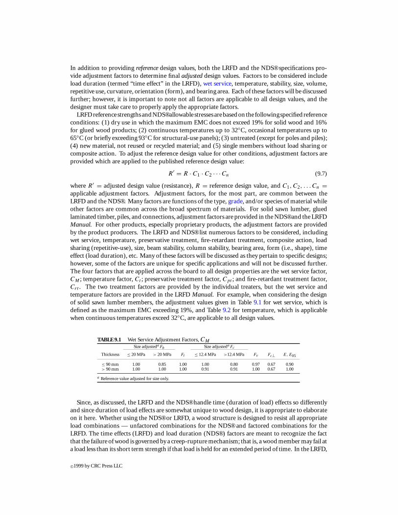
TABLE 9.2 Temperature Adjustment Factors, Ct
Dry use Wet use
Sustained temperature (◦C) E, E05 All other prop. E, E05 All other prop.
32 < T ≤ 48 0.9 0.8 0.9 0.748 < T ≤ 65 0.9 0.7 0.9 0.5
the time effect factor, λ, is based on the load combination being considered as given in Table 9.3. Inthe NDS® , the load duration factor, CD , is given in terms of the assumed cumulative duration ofthe design load. Table 9.4 provides commonly used load duration factors with the associated loadcombination.
TABLE 9.3 Time Effects Factors for Use in LRFDLoad combination Time effect factor, λ
1.4D 0.61.2D+ 1.6L+ 0.5(Lr or S or R) 0.7 when L from storage
0.8 when L from occupancy1.25 when L from impacta
1.2D+ 1.6(Lr or S or R) + (0.5L or 0.8W ) 0.81.2D+ 1.3W+ 0.5L+ 0.5(Lr or S or R) 1.01.2D+ 1.0E+ 0.5L+ 0.2S 1.00.9D−(1.3W or 1.0E) 1.0
a For impact loading on connections, λ = 1.0 rather than 1.25.From Load and Resistance Factor Design (LRFD) for Engineered Wood Construction,American Society of Civil Engineers (ASCE), AF&PA/ASCE 16-95. ASCE, NewYork, 1996. With permission.
TABLE 9.4 Load Duration Factors for Use in NDS®Load duration
Load duration Load type Load combination factor, CD
Permanent Dead D 0.9Ten years Occupancy live D + L 1.0Two months Snow load D + L + S 1.15Seven days Construction live D + L + Lr 1.25Ten minutes Wind and D + (W or E) and 1.6
earthquake D + L + (Lr or S or R) + (W or E)Impact Impact loads D + L (L from impact) 2.0a
a For impact loading on connections, λ = 1.6 rather than 2.0.From National Design Specification for Wood Construction and Supplement, American Forest and PaperAssociation (AF&PA), Washington, D.C., 1991. With permission.
Adjusted design values, whether they are allowable stresses or nominal strengths, are established inthe same basic manner: the reference value is taken from an appropriate source (e.g., the LRFD Man-ual [1] or manufacture product literature) and is adjusted for various end-use conditions (e.g., wetuse, load sharing, etc.). Additionally, depending on the design load combination being considered,a time effect factor (LRFD) or a load duration factor (NDS®) is applied to the adjusted resistance.Obviously, this rather involved procedure is critical, and somewhat unique, to wood design.
9.4 Beam Design
Bending members are perhaps the most common structural element. The design of wood beamsfollows traditional beam theory but, as mentioned previously, allowances must be made for the
c©1999 by CRC Press LLC
conditions and duration of loads expected for the structure. Additionally, many times bendingmembers are not used as single elements, but rather as part of integrated systems such as a floor orroof system. As such, there exists a degree of member interaction (i.e., load sharing) which can beaccounted for in the design. Wood bending members include sawn lumber, timber, glued laminatedtimber, SCL, and I-joists.
9.4.1 Moment Capacity
The flexural strength of a beam is generally the primary concern in a beam design, but considerationof other factors such as horizontal shear, bearing, and deflection are also crucial for a successfuldesign. Strength considerations will be addressed here while serviceability design (i.e., deflection,etc.) will be presented in Section 9.13. In terms of moment, the LRFD [5] design equation is
Mu ≤ λφbM′ (9.8)
whereMu = moment caused by factored loadsλ = time effect factor applicable for the load combination under considerationφb = resistance factor for bending = 0.85M ′ = adjusted moment resistance
The moment caused by the factored load combination, Mu, is determined through typical methodsof structural analysis. The assumption of linear elastic behavior is acceptable, but a nonlinear analysisis acceptable if supporting data exists for such an analysis. The resistance values, however, involveconsideration of factors such as lateral support conditions and whether the member is part of a largerassembly.
Published design values for bending are given for use in the LRFD by AF&PA [1] in the form ofa reference bending strength (stress), Fb. This value assumes strong axis orientation; an adjustmentfactor for flat-use, Cf u, can be used if the member will be used about the weak axis. Therefore, forstrong (x − x) axis bending, the moment resistance is
M ′ = M ′x = Sx · F ′
b (9.9)
and for weak (y − y) axis bending
M ′ = M ′y = Sy · Cf u · F ′
b (9.10)
whereM ′ = M ′
x = adjusted strong axis moment resistanceM ′ = M ′
y = adjusted weak axis moment resistanceSx = section modulus for strong axis bendingSy = section modulus for weak axis bendingF ′
b = adjusted bending strengthFor bending, typical adjustment factors to be considered include wet service, CM ; temperature,
Ct ; beam stability, CL; size, CF ; volume (for glued laminated timber only), CV ; load sharing, Cr ;form (for non-rectangular sections), Cf ; and curvature (for glued laminated timber), Cc; and, ofcourse, flat-use, Cf u. Many of these factors, including the flat-use factor, are functions of specificproduct types and species of materials, and therefore are provided with the reference design values.The two factors worth discussion here are the beam stability factor, which accounts for possiblelateral-torsional buckling of a beam, and the load sharing factor, which accounts for system effectsin repetitive assemblies.
The beam stability factor, CL, is only used when considering strong axis bending since a beam ori-ented about its weak axis is not susceptible to lateral instability. Additionally, the beam stability factor
c©1999 by CRC Press LLC
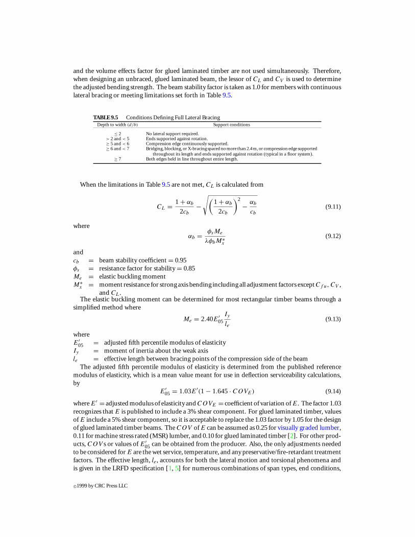
and the volume effects factor for glued laminated timber are not used simultaneously. Therefore,when designing an unbraced, glued laminated beam, the lessor of CL and CV is used to determinethe adjusted bending strength. The beam stability factor is taken as 1.0 for members with continuouslateral bracing or meeting limitations set forth in Table 9.5.
TABLE 9.5 Conditions Defining Full Lateral BracingDepth to width (d/b) Support conditions
≤ 2 No lateral support required.> 2 and < 5 Ends supported against rotation.≥ 5 and < 6 Compression edge continuously supported.≥ 6 and < 7 Bridging, blocking, or X-bracing spaced no more than 2.4 m, or compression edge supported
throughout its length and ends supported against rotation (typical in a floor system).≥ 7 Both edges held in line throughout entire length.
When the limitations in Table 9.5 are not met, CL is calculated from
CL = 1 + αb
2cb
−√(
1 + αb
2cb
)2
− αb
cb
(9.11)
where
αb = φsMe
λφbM∗x
(9.12)
andcb = beam stability coefficient = 0.95φs = resistance factor for stability = 0.85Me = elastic buckling momentM∗
x = moment resistance for strong axis bending including all adjustment factors exceptCf u, CV ,and CL.
The elastic buckling moment can be determined for most rectangular timber beams through asimplified method where
Me = 2.40E′05
Iy
le(9.13)
whereE′
05 = adjusted fifth percentile modulus of elasticityIy = moment of inertia about the weak axisle = effective length between bracing points of the compression side of the beam
The adjusted fifth percentile modulus of elasticity is determined from the published referencemodulus of elasticity, which is a mean value meant for use in deflection serviceability calculations,by
E′05 = 1.03E′(1 − 1.645· COVE) (9.14)
where E′ = adjusted modulus of elasticity and COVE = coefficient of variation of E. The factor 1.03recognizes that E is published to include a 3% shear component. For glued laminated timber, valuesof E include a 5% shear component, so it is acceptable to replace the 1.03 factor by 1.05 for the designof glued laminated timber beams. The COV of E can be assumed as 0.25 for visually graded lumber,0.11 for machine stress rated (MSR) lumber, and 0.10 for glued laminated timber [2]. For other prod-ucts, COV s or values of E′
05 can be obtained from the producer. Also, the only adjustments neededto be considered for E are the wet service, temperature, and any preservative/fire-retardant treatmentfactors. The effective length, le, accounts for both the lateral motion and torsional phenomena andis given in the LRFD specification [1, 5] for numerous combinations of span types, end conditions,
c©1999 by CRC Press LLC
loading, bracing conditions, and actual unsupported span to depth ratios (lu/d). Generally, forlu/d < 7, the effective unbraced length, le, ranges from 1.33lu to 2.06lu; for 7≤ lu/d ≤ 14.3, le rangesfrom 1.11lu to 1.84lu; and for lu/d > 14.3, le ranges from 0.9lu +3d to 1.63lu +3d where d = depthof the beam.
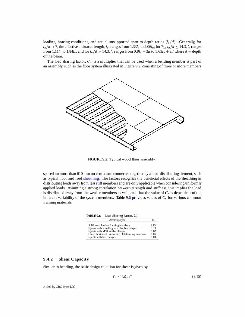
The load sharing factor, Cr , is a multiplier that can be used when a bending member is part ofan assembly, such as the floor system illustrated in Figure 9.2, consisting of three or more members
FIGURE 9.2: Typical wood floor assembly.
spaced no more than 610 mm on center and connected together by a load-distributing element, suchas typical floor and roof sheathing. The factors recognize the beneficial effects of the sheathing indistributing loads away from less stiff members and are only applicable when considering uniformlyapplied loads. Assuming a strong correlation between strength and stiffness, this implies the loadis distributed away from the weaker members as well, and that the value of Cr is dependent of theinherent variability of the system members. Table 9.6 provides values of Cr for various commonframing materials.
TABLE 9.6 Load Sharing Factor, Cr
Assembly type Cr
Solid sawn lumber framing members 1.15I-joists with visually graded lumber flanges 1.15I-joists with MSR lumber flanges 1.07Glued laminated timber and SCL framing members 1.05I-joists with SCL flanges 1.04
9.4.2 Shear Capacity
Similar to bending, the basic design equation for shear is given by
Vu ≤ λφvV′ (9.15)
c©1999 by CRC Press LLC

whereVu = shear caused by factored loadsλ = time effect factor applicable for the load combination under considerationφv = resistance factor for shear = 0.75V ′ = adjusted shear resistance
Except in the design of I-joists, Vu is determined at a distance d (depth of the member) away fromthe face of the support if the loads acting on the member are applied to the face opposite the bearingarea of the support. For other loading conditions and for I-joists, Vu is determined at the face of thesupport.
The adjusted shear resistance is computed from
V ′ = F ′vIb
Q(9.16)
whereF ′
v = adjusted shear strength parallel to the grainI = moment of inertiab = member widthQ = statical moment of an area about the neutral axis
For rectangular sections, this equation simplifies to
V ′ = 2
3F ′
vbd (9.17)
where d = depth of the rectangular section.The adjusted shear strength, F ′
v , is determined by multiplying the published reference shearstrength, Fv , by all appropriate adjustment factors. For shear, typical adjustment factors to beconsidered include wet service, CM ; temperature, Ct ; size, CF ; and shear stress, CH . The shear stressfactor allows for increased shear strength in members with limited splits, checks, and shakes andranges from CH = 1.0 implying the presence of splits, checks, and shakes to CH = 2.0 implying nosplits, checks, or shakes.
In wood construction, notches are often made at the support to allow for vertical clearances andtolerances as illustrated in Figure 9.3; however, stress concentrations resulting from these notchessignificantly affect the shear resistance of the section. At sections where the depth is reduced due tothe presence of a notch, the shear resistance of the notched section is determined from
V ′ =(
2
3F ′
vbdn
) (dn
d
)(9.18)
where d = depth of the unnotched section and dn = depth of the member after the notch. When thenotch is made such that it is actually a gradual tapered cut at an angle θ from the longitudinal axisof the beam, the stress concentrations resulting from the notch are reduced and the above equationbecomes
V ′ =(
2
3F ′
vbdn
) (1 − (d − dn) sinθ
d
)(9.19)
Similar to notches, connections too can produce significant stress concentrations resulting inreduced shear capacity. Where a connection produces at least one-half the member shear force oneither side of the connection, the shear resistance is determined by
V ′ =(
2
3F ′
vbde
) (de
d
)(9.20)
c©1999 by CRC Press LLC
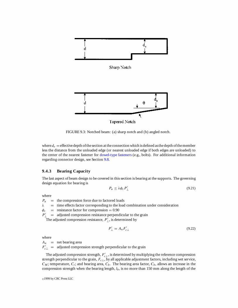
FIGURE 9.3: Notched beam: (a) sharp notch and (b) angled notch.
wherede = effectivedepthof the sectionat the connectionwhich isdefinedas thedepthof thememberless the distance from the unloaded edge (or nearest unloaded edge if both edges are unloaded) tothe center of the nearest fastener for dowel-type fasteners (e.g., bolts). For additional informationregarding connector design, see Section 9.8.
9.4.3 Bearing Capacity
The last aspect of beam design to be covered in this section is bearing at the supports. The governingdesign equation for bearing is
Pu ≤ λφcP′⊥ (9.21)
wherePu = the compression force due to factored loadsλ = time effects factor corresponding to the load combination under considerationφc = resistance factor for compression = 0.90P ′⊥ = adjusted compression resistance perpendicular to the grain
The adjusted compression resistance, P ′⊥, is determined by
P ′⊥ = AnF′c⊥ (9.22)
whereAn = net bearing areaF ′
c⊥ = adjusted compression strength perpendicular to the grain
The adjusted compression strength, F ′c⊥, is determined by multiplying the reference compression
strength perpendicular to the grain, Fc⊥, by all applicable adjustment factors, including wet service,CM ; temperature, Ct ; and bearing area, Cb. The bearing area factor, Cb, allows an increase in thecompression strength when the bearing length, lb, is no more than 150 mm along the length of the
c©1999 by CRC Press LLC
member and is at least 75 mm from the end of the member, and is given by
Cb = (lb + 9.5)/ lb (9.23)
where lb is in mm.
9.4.4 NDS® Provisions
In the ASD format provided by the NDS® , the design checks are in terms of allowable stressesand unfactored loads. The determined bending, shear, and bearing stresses in a member due tounfactored loads are required to be less than the adjusted allowable bending, shear, and bearingstresses, respectively, including load duration effects. The basic approach to the design of a beamelement, however, is quite similar between the LRFD and NDS® and is based on the same principlesof mechanics. One major difference between the two specifications, though, is the treatment of loadduration effects with respect to bearing. In the LRFD, the design equation for bearing (Equation 9.21)includes the timeeffect factor,λ; however, theNDS®doesnot requireanyadjustment for loaddurationfor bearing. The allowable compressive stress perpendicular to the grain as presented in the NDS®is not adjusted because the compressive stress perpendicular to the grain follows a deformationdefinition of failure rather than fracture as in all other modes; thus, the adjustment is consideredunnecessary. Conversely, the LRFD specification assumes time effects to occur in all modes, whetherit is strength- (fracture) based or deformation-based.
9.5 Tension Member Design
The design of tension members, either by LRFD or NDS®, is relatively straightforward. The basicdesign checking equation for a tension member as given by the LRFD Specification [5] is
Tu ≤ λφtT′ (9.24)
where
Tu = the tension force due to factored loads
λ = time effects factor corresponding to the load combination under consideration
φt = resistance factor for tension = 0.80
T ′ = adjusted tension resistance parallel to the grain
The adjusted compression resistance, T ′, is determined by
T ′ = AnF′t (9.25)
where An = net cross-sectional area and F ′t = adjusted tension strength parallel to the grain.
The adjusted compression strength, F ′t , is determined by multiplying the reference tension strength
parallel to the grain, Ft , by all applicable adjustment factors, including wet service, CM ; temperature,Ct ; and size, CF .
It should be noted that tension forces are typically transferred to a member through some type ofmechanical connection. When, for example as illustrated in Figure 9.4, the centroid of an unsym-metric net section of a group of three or more connectors differs by 5% or more from the centroidof the gross section, then the tension member must be designed as a combined tension and bendingmember (see Section 9.7).
c©1999 by CRC Press LLC
FIGURE 9.4: Eccentric bolted connection.
9.6 Column Design
The term column is typically considered to mean any compression member, including compressivemembers in trusses and posts as well as traditional columns. Three basic types of wood columns asillustrated in Figure 9.5 are (1) simple solid or traditional columns, which are single members such assawn lumber, posts, timbers, poles, glued laminated timber, etc.; (2) spaced columns, which are twoor more parallel single members separated at specific locations along their length by blocking andrigidly tied together at their ends; and (3) built-up columns, which consist of two or more membersjoined together by mechanical fasteners such that the assembly acts as a single unit.
Dependingon the relativedimensionsof the columnasdefinedby the slenderness ratio, thedesignofwood columns is limited by the material’s stiffness and strength parallel to the grain. The slendernessratio is defined as the ratio of the effective length of the column, le, to the least radius of gyration,r = √
I/A , where I = moment of inertia of the cross-section about the weak axis and A =cross-sectional area. The effective length is defined by le = Kel, where Ke = effective length factoror buckling length coefficient and l = unbraced length of the column. The unbraced length, l, ismeasured as center to center distance between lateral supports. Ke is dependent on the column endsupport conditions and on whether sidesway is allowed or restrained. Table 9.7 provides values ofKe for various typical column configurations. Regardless of the column type of end conditions, theslenderness ratio, Kel/r , is not permitted to exceed 175.
9.6.1 Solid Columns
The basic design equation for an axially loaded member as given by the LRFD Specification [5] isgiven as
Pu ≤ λφcP′c (9.26)
wherePu = the compression force due to factored loads
c©1999 by CRC Press LLC
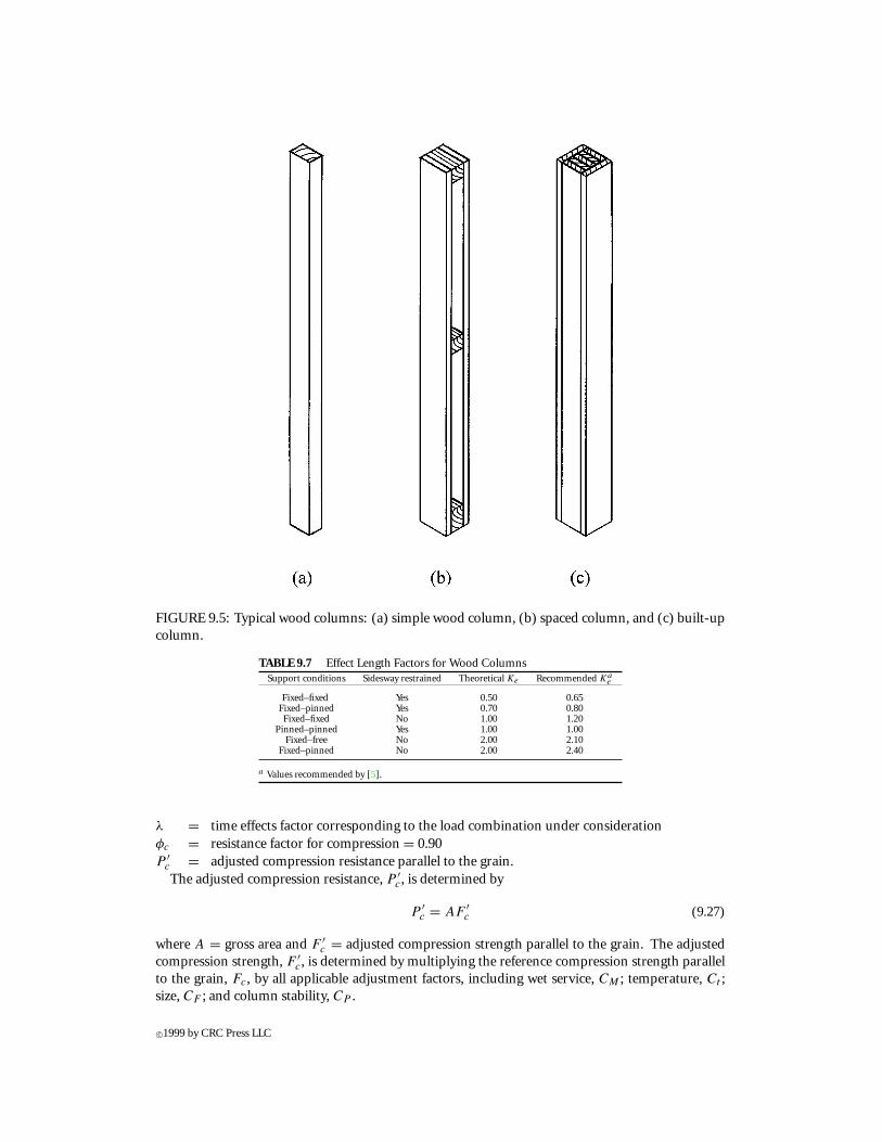
FIGURE 9.5: Typical wood columns: (a) simple wood column, (b) spaced column, and (c) built-upcolumn.
TABLE 9.7 Effect Length Factors for Wood ColumnsSupport conditions Sidesway restrained Theoretical Ke Recommended Ka
e
Fixed–fixed Yes 0.50 0.65Fixed–pinned Yes 0.70 0.80Fixed–fixed No 1.00 1.20
Pinned–pinned Yes 1.00 1.00Fixed–free No 2.00 2.10
Fixed–pinned No 2.00 2.40
a Values recommended by [5].
λ = time effects factor corresponding to the load combination under considerationφc = resistance factor for compression = 0.90P ′
c = adjusted compression resistance parallel to the grain.The adjusted compression resistance, P ′
c, is determined by
P ′c = AF ′
c (9.27)
where A = gross area and F ′c = adjusted compression strength parallel to the grain. The adjusted
compression strength, F ′c, is determined by multiplying the reference compression strength parallel
to the grain, Fc, by all applicable adjustment factors, including wet service, CM ; temperature, Ct ;size, CF ; and column stability, CP .
c©1999 by CRC Press LLC
The column stability factor, CP , accounts for partial lateral support for a column and is given by
Cp = 1 + αc
2c−
√(1 + αc
2c
)2
− αc
c(9.28)
where
αc = φsPe
λφcP′0
(9.29)
Pe = π2E′05A(
Kelr
)2(9.30)
and c = coefficient based on member type, φs = resistance factor for stability = 0.85, φb = resistancefactor for compression = 0.90, λ = time effect factor for load combination under consideration, Pe =Euler buckling resistance, P ′
0 = adjusted resistance of a fully braced (or so-called “zero-length”)column, E′
05 = adjusted fifth percentile modulus of elasticity, and A = gross cross-sectional area.The coefficient c = 0.80 for solid sawn members, 0.85 for round poles and piles, and 0.90 for gluedlaminated members and SCL. E′
05 is determined as presented for beam stability using Equation 9.14,and P ′
0 is determined using Equation 9.27, except that the reference compression strength, Fc, is notadjusted for stability (i.e., assume CP = 1.0).
Two common conditions occurring in solid columns are notches and tapers. When notches orholes are present in the middle half of the effective length (between inflection points), and the netmoment of inertia at the notch or hole is less than 80% of the gross moment of inertia, or the lengthof the notch or hole is greater than the largest cross-sectional dimension of the column, then P ′
c
(Equation 9.27) and CP (Equation 9.28) are computed using the net area, An, rather than gross area,A. When notches or holes are present outside this region, the column resistance is taken as the lesserof that determined without considering the notch or hole (i.e., using gross area) and
P ′c = AnF
∗c (9.31)
where F ∗c = the compression strength adjusted by all applicable factors except for stability (i.e.,
assume CP = 1.0).Two basic types of uniformly tapered solid columns exist: circular and rectangular. For circular
tapered columns, the design diameter is taken as either (1) the diameter of the small end or (2) whenthe diameter of the small end, D1, is at least one-third of the large end diameter, D2,
D = D1 + X(D2 − D1) (9.32)
where D = design diameter and X = a factor dependent on support conditions as follows:
1. Cantilevered, large end fixed: X = 0.52+ 0.18(D1/D2) (9.33a)
2. Cantilevered, small end fixed: X = 0.12+ 0.18(D1/D2) (9.33b)
3. Singly tapered, simple supports: X = 0.32+ 0.18(D1/D2) (9.33c)
4. Doubly tapered, simple supports: X = 0.52+ 0.18(D1/D2) (9.33d)
5. All other support conditions: X = 0.33 (9.33e)
For uniformly tapered rectangular columns with constant width, the design depth of the memberis handled in a manner similar to circular tapered columns, except that buckling in two directions
c©1999 by CRC Press LLC
must be considered. The design depth is taken as either (1) the depth of the small end or (2) whenthe depth of the small end, d1, is at least one-third of the large end depth, d2,
d = d1 + X(d2 − d1) (9.34)
where d = design depth and X = a factor dependent on support conditions as follows:For buckling in the tapered direction:
1. Cantilevered, large end fixed: X = 0.55+ 0.15(d1/d2) (9.35a)
2. Cantilevered, small end fixed: X = 0.15+ 0.15(d1/d2) (9.35b)
3. Singly tapered, simple supports: X = 0.35+ 0.15(d1/d2) (9.35c)
4. Doubly tapered, simple supports: X = 0.55+ 0.15(d1/d2) (9.35d)
5. All other support conditions: X = 0.33 (9.35e)
For buckling in the non-tapered direction:
1. Cantilevered, large end fixed: X = 0.63+ 0.07(d1/d2) (9.35f)
2. Cantilevered, small end fixed: X = 0.23+ 0.07(d1/d2) (9.35g)
3. Singly tapered, simple supports: X = 0.43+ 0.07(d1/d2) (9.35h)
4. Doubly tapered, simple supports: X = 0.63+ 0.07(d1/d2) (9.35i)
5. All other support conditions: X = 0.33 (9.35j)
In addition to these provisions, the design resistance of a tapered circular or rectangular columncannot exceed
P ′c = AnF
∗c (9.36)
where An = net area of the column at any cross-section and F ∗c = the compression strength adjusted
by all applicable factors except for stability (i.e., assume CP = 1.0).
9.6.2 Spaced Columns
Spaced columns consist of two or more parallel single members separated at specific locations alongtheir length by blocking and rigidly tied together at their ends. As defined in Figure 9.5b, L1 =overall length in the spaced column direction, L2 = overall length in the solid column direction,L3 = largest distance from the centroid of an end block to the center of the mid-length spacer,Lce = distance from the centroid of end block connectors to the nearer column end, d1 = width ofindividual components in the spaced column direction, and d2 = width of individual components inthe solid column direction. Typically, the individual components of a spaced column are consideredto act individually in the direction of the wide face of the members. The blocking, however, effectivelyreduces the unbraced length in the weak direction. Therefore, the following L/d ratios are imposedon spaced columns:
1. In the spaced column direction: L1/d1 ≤ 80 (9.37a)
L3/d1 ≤ 40 (9.37b)
2. In the solid column direction:2 L2/d2 ≤ 50 (9.37c)
c©1999 by CRC Press LLC
Depending on the length Lce relative to L1, one of two effective length factors can be assumed fordesign in the spaced column direction. If sidesway is not allowed andLce ≤ 0.05L1, then the effectivelength factor is assumed as Ke = 0.63; or if there is no sidesway and 0.05L1 < Lce ≤ 0.10L1, thenassume Ke = 0.53. For columns with sidesway in the spaced column direction, an effective lengthfactor greater than unity is determined as given in Table 9.7.
9.6.3 Built-Up Columns
Built-up columns consist of two or more members joined together by mechanical fasteners such thatthe assembly acts as a single unit. Conservatively, the capacity of a built-up member can be taken asthe sum of resistances of the individual components. Conversely, if information regarding the rigidityand overall effectiveness of the fasteners is available, the designer can incorporate such informationinto the analysis and take advantage of the composite action provided by the fasteners; however, nocodified procedures are available for the design of built-up columns. In either case, the fastenersmust be designed appropriately to resist the imposed shear and tension forces (see Section 9.8 forfastener design).
9.6.4 NDS® Provisions
For rectangular columns, which are common in wood construction, the slenderness ratio can beexpressed as the ratio of the unbraced length to the least cross-sectional dimension of the column,or L/d where d is the least cross-sectional dimension. This is the approach offered by the NDS®[2] which differs from the more general approach of the LRFD [5] and is identical to that used inthe LRFD for spaced columns. Often, the unbraced length of a column is not the same about boththe strong and weak axes and the slenderness ratios in both directions should be considered (e.g.,r1 = L1/d1 in the strong direction and r2 = L2/d2 in the weak direction). One common example ofsuch a case is wood studs in a load bearing wall where, if adequately fastened, the sheathing providescontinuous lateral support in the weak direction and only the slenderness ratio about the strongaxis needs to be determined. The slenderness ratio is not permitted to exceed 502 for single solidcolumns or built-up columns, and is not permitted to exceed 80 for individual members of spacedcolumns; however, when used for temporary construction bracing, the allowable slenderness ratio isincreased from 50 to 75 for single or built-up columns. All other provisions related to column designare equivalent between the NDS® and LRFD.
9.7 Combined Load Design
Often, structural wood members are subjected to bending about both principal axes and/or bendingcombined with axial loads. The bending can come from eccentric axial loads and/or laterally appliedloads. The adjusted member resistances for moment, M ′, tension, T ′, and compression, P ′
c, definedin Sections 9.4, 9.5, and 9.6 are used for combined load design in conjunction with an appropriateinteraction equation. All other factors (e.g., the resistance factors φb, φt , and φc, and the time effectfactor, λ) are also the same in combined load design as defined previously.
2For rectangular columns, the provision L/d ≤ 50 is equivalent to the provision KL/r ≤ 175.
c©1999 by CRC Press LLC
9.7.1 Combined Bending and Axial Tension
When a tension load acts simultaneously with bending about one or both principal axes, the followinginteraction equations must be satisfied:
1. Tension face:Tu
λφtT ′ + Mux
λφbM ′s
+ Muy
λφbM ′y
≤ 1.0 (9.38)
2. Compression face:
(Mux − d
6Tu
)λφbM ′
x
+ Muy
λφb
(1 − Mux
φbMe
)2≤ 1.0 (9.39)
whereTu = tension force due to factored loadsMux and Muy = moment due to factored loads about the strong and weak axes, respectivelyM ′
x and M ′y = adjusted moment resistance about the strong and weak axes, respectively
Me = elastic lateral buckling moment (Equation 9.13)M ′
s = M ′x computed assuming the beam stability factor CL = 1.0 but including all
other appropriate adjustment factors, including the volume factor CV
d = depth of the memberEquations9.38and9.39assumerectangular sections. If anon-rectangular section isbeingdesigned,
the quantity d/6 appearing in Equation 9.38 should be replaced by Sx/A where Sx = the sectionmodulus about the strong axis and A = gross area of the section.
9.7.2 Biaxial Bending or Combined Bending and Axial Compression
When a member is being designed for either biaxial bending or for combined axial compression andbending about one or both principal axes, the following interaction equation must be satisfied:
(Pu
λφcP ′c
)2
+ Mmx
λφbM ′x
+ Mmy
λφbM ′y
≤ 1.0 (9.40)
wherePu = axial load due to factored loadsP ′
c = adjusted compression resistance assuming the compression acts alone (i.e., nomoments) for the axis of buckling providing the lower resistance value
Mmx and Mmy = moments due to factored loads, including any magnification resulting fromsecond-order moments, about the strong and weak axes, respectively
M ′x and M ′
y = adjusted strong and weak axes moment resistances, respectively, assuming thebeam stability factor CL = 1.0
The moments due to factored loads, Mmx andMmy , can be determined either of two ways: (1) usingan appropriate second-order analysis procedure or (2) using a simplified magnification method. Themoment magnification method recommended in the LRFD is given as follows:
Mmx = BbxMbx + BsxMsx (9.41)
Mmy = BbyMby + BsyMsy (9.42)
whereMbx andMby = factored strong and weak axis moments, respectively, from loads producing nolateral translation or sidesway determined using an appropriate first-order analysis; Msx and Msy =factored strong and weak axis moments, respectively, from loads producing lateral translation orsideswaydeterminedusinganappropriatefirst-order analysis; andBbx, Bsx, Bby , andBsy =moment
c©1999 by CRC Press LLC
magnification factors to account for second-order effects and associated with Mbx, Msx, Mby , andMsy , respectively, and are determined as follows:
Bbx = Cmx(1 − Pu
φcPex
) ≥ 1.0 (9.43)
Bby = Cmx[1 − Pu
φcPex−
(Mux
φbMe
)2] ≥ 1.0 (9.44)
Bsx = 1(1 − 6Pu
φc6Pex
) ≥ 1.0 (9.45)
Bsy = 1(1 − 6Pu
φc6Pey
) ≥ 1.0 (9.46)
wherePex and Pey = Euler buckling resistance about the strong and weak axes, respectively, as
determined by Equation 9.30∑Pu = sum of all compression forces due to factored loads for all columns in the
sidesway mode under consideration∑Pex and
∑Pey = sum of all Euler buckling resistances for columns in the sidesway mode
under consideration about its strong and weak axes, respectivelyCmx and Cmy = factor relating the actual moment diagram shape to an equivalent uniform
moment diagram for moment applied about the strong and weak axes,respectively
All other terms are as defined previously. The factors Cmx and Cmy are determined for one of twoconditions:
1. For members braced against lateral joint translation with only end moments applied:
Cmx or Cmy = 0.60− 0.40M1
M2(9.47)
where M1/M2 = ratio of the smaller magnitude end moment to the larger end momentin the plane of bending (x − x or y − y) under consideration, with the ratio defined asbeing negative for single curvature and positive for double curvature.
2. For members braced against joint translation in the plane of bending under considerationwith lateral loads applied between the joints:
a) Cmx or Cmy = 0.85 for members with ends restrained against rotation, or
b) Cmx or Cmy = 1.00 for members with ends unrestrained against rotation.
For members not braced against sidesway, all four moment magnification factors need to bedetermined; however, for members braced against sidesway, only Bbx and Bsx need to be determined.
9.7.3 NDS® Provisions
The primary difference between the LRFD approach for members subjected to combined load andthat of the NDS® is in the design of members for combined axial and bending loads. The LRFDcombines moments from all sources, including moments from eccentrically applied axial loads and
c©1999 by CRC Press LLC
moments from transversely applied loads. The NDS® provides the following general interactionequation:
(fc
F ′c
)2
+fbx + fc
(6ey
dy
) (1 + 0.234 fc
FcEx
)F ′
bx
(1 − fc
FcEx
)
+fby + fc
(6ex
dx
) (1 + 0.234 fc
FcEy
)F ′
by
[1 − fc
FcEy−
(fbx
FbE
)2] ≤ 1.0 (9.48)
wherefc = compression stress due to unfactored loadsfbx and fby = bending stress about the strongandweakaxes, respectively, due tounfactored
loadsF ′
c = adjusted allowable compression stressF ′
bx and Fby = adjustedallowablebending stress about the strongandweakaxes, respectivelyFcEx and FcEy = allowable Euler buckling stress about the strong and weak axes, respectivelyFbE = allowable buckling stress for bendingex and ey = eccentricity in the x and y directions, respectivelydx and dy = cross-sectional dimension in the x (narrow dimension) and y (wide dimen-
sion) directions, respectivelyThe allowable buckling values are determined from
FcEx = KcEE′
(lex/dx)2
(9.49)
FcEy = KcEE′(ley/dy
)2(9.50)
FbE = KbEE′
(Rb)2(9.51)
whereKce = 0.3 for visually graded and machine evaluated lumber, or 0.418 for products with a coef-
ficient of variation on E less than or equal to 11% (e.g., MSR lumber and glued laminatedtimber)
KbE = 0.438 for visually graded and machine evaluated lumber, or 0.609 for products with acoefficient of variation onE less than or equal to 11%
E′ = adjusted modulus of elasticityRb = slenderness ratio for bending as given by
Rb =√
leydy
d2x
(9.52)
Note that ley is used in Equation 9.52 since lateral buckling in beams is only possible about theweak axis.
9.8 Fastener and Connection Design
The design of fasteners and connections for wood has undergone significant changes in recent years.Typical fastener and connection details for wood include nails, staples, screws, lag screws, dowels,
c©1999 by CRC Press LLC
and bolts. Additionally, split rings, shear plates, truss plate connectors, joist hangers, and many othertypes of connectors are available to the designer. The general LRFD design checking equation forconnections is given as follows:
Zu ≤ λφzZ′ (9.53)
whereZu = connection force due to factored loadsλ = applicable time effect factorφz = resistance factor for connections = 0.65Z′ = connection resistance adjusted by the appropriate adjustment factors
It should be noted that, for connections, the moisture adjustment is based on both in servicecondition and on conditions at the time of fabrication; that is, if a connection is fabricated in thewet condition but is to be used in service under a dry condition, the wet condition should be usedfor design purposes due to potential drying stresses which may occur. Also, CM does not accountfor corrosion of metal components in a connection. Other adjustments specific to connection type(e.g., diaphragm factor, Cdi ; end grain factor, Ceg ; group action factor, Cg ; geometry factor, C1;penetration depth factor, Cd ; toe-nail factor, Ctn; etc.) will be discussed with their specific use. Itshould also be noted that the time effects factor, λ, is not allowed to exceed unity for connections asnoted in Table 9.3. Additionally, when failure of a connection is controlled by a non-wood element(e.g., fracture of a bolt), then the time-effects factor is taken as unity since time effects are specific towood and not applicable to non-wood components.
In both the LRFD Manual [1] and the NDS® [2], tables of reference resistances (LRFD) andallowable loads (NDS®) are available which significantly reduce the tedious calculations required fora simple connection design. In this section, the basic design equations and calculation procedures arepresented, but design tables such as those given in the LRFD Manual and the NDS® are not providedhere.
The design of general dowel-type connections (i.e., nails, spikes, screws, bolts, etc.) for lateralloading are currently based on possible yield modes. Formerly (i.e., all previous editions of theNDS®), empirical behavior equations were the basis for the design provisions. Figure 9.6 illustratesthe various yield modes that must be considered for single and double shear connections. Based onthese possible yield modes, lateral resistances are determined for the various dowel-type connections.Specific equations are presented in the following sections for nails and spikes, screws, bolts, and lagscrews. In general, though, the dowel bearing strength, Fe, is required to determine the lateralresistance of a dowel-type connection. Obviously, this property is a function of the orientation of theapplied load to the grain, and values ofFe are available for parallel to the grain, Fe‖, and perpendicularto the grain, Fe⊥. The dowel bearing strength or other angles to the grain, Feθ , is determined by
Feθ = Fe‖Fe⊥Fe‖ sin2 θ + Fe⊥ cos2 θ
(9.54)
where θ = angle of load with respect to a direction parallel to the grain.
9.8.1 Nails, Spikes, and Screws
Nails and spikes are perhaps the most commonly used fasteners in wood construction. Nails aregenerally used when loads are light such as in the construction of diaphragms and shear walls;however, they are susceptible to working loose under vibration or withdrawal loads. Common wirenails and spikes are quite similar, except that spikes have larger diameters than nails. Both a 12d(i.e., 12-penny) nail and spike are 88.9 mm in length; however, a 12d nail has a diameter of 3.76mm while a spike has a diameter of 4.88 mm. Many types of nails have been developed to provide
c©1999 by CRC Press LLC
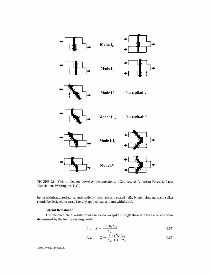
FIGURE 9.6: Yield modes for dowel-type connections. (Courtesy of American Forest & PaperAssociation, Washington, D.C.)
better withdrawal resistance, such as deformed shank and coated nails. Nonetheless, nails and spikesshould be designed to carry laterally applied load and not withdrawal.
Lateral Resistance
The reference lateral resistance of a single nail or spike in single shear is taken as the least valuedetermined by the four governing modes:
Is : Z = 3.3DtsFes
KD
(9.55)
IIIm : Z = 3.3k1DpFem
KD(1 + 2Re)(9.56)
c©1999 by CRC Press LLC
IIIs : Z = 3.3k2DtsFem
KD(2 + Re)(9.57)
IV : Z = 3.3D2
KD
√2FemFyb
3(1 + Re)(9.58)
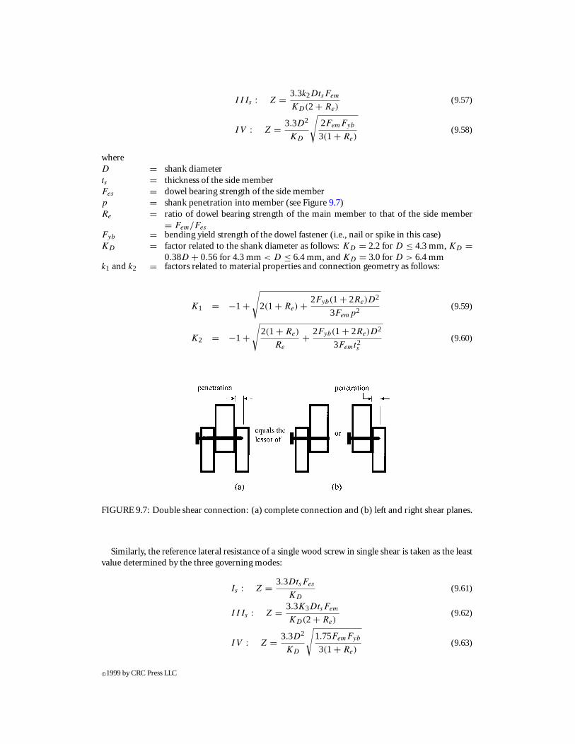
whereD = shank diameterts = thickness of the side memberFes = dowel bearing strength of the side memberp = shank penetration into member (see Figure 9.7)Re = ratio of dowel bearing strength of the main member to that of the side member
= Fem/Fes
Fyb = bending yield strength of the dowel fastener (i.e., nail or spike in this case)KD = factor related to the shank diameter as follows: KD = 2.2 for D ≤ 4.3 mm, KD =
0.38D + 0.56 for 4.3 mm < D ≤ 6.4 mm, and KD = 3.0 for D > 6.4 mmk1 and k2 = factors related to material properties and connection geometry as follows:
K1 = −1 +√
2(1 + Re) + 2Fyb(1 + 2Re)D2
3Femp2(9.59)
K2 = −1 +√
2(1 + Re)
Re
+ 2Fyb(1 + 2Re)D2
3Femt2s
(9.60)
FIGURE 9.7: Double shear connection: (a) complete connection and (b) left and right shear planes.
Similarly, the reference lateral resistance of a single wood screw in single shear is taken as the leastvalue determined by the three governing modes:
Is : Z = 3.3DtsFes
KD
(9.61)
IIIs : Z = 3.3K3DtsFem
KD(2 + Re)(9.62)
IV : Z = 3.3D2
KD
√1.75FemFyb
3(1 + Re)(9.63)
c©1999 by CRC Press LLC
where KD is defined for wood screws as it was for nails and spikes, and K3 = a factor related tomaterial properties and connection geometry as follows:
K3 = −1 +√
2(1 + Re)
Re
+ Fyb(2 + Re)D2
2Femt2s
(9.64)
For nail, spike, or wood screw connections with steel side plates, the above equations for yield modeIs are not appropriate. Rather, the resistance for that mode should be computed as the bearingresistance of the fastener on the steel side plate. Also, when double shear connections are designed(Figure 9.7a), the reference lateral resistance is taken as twice the resistance of the weaker single shearrepresentation of the left and right shear planes (Figure 9.7b).
For multi-nail, spike, or wood screw connections, the least resistance, as determined from Equa-tions 9.55 through 9.58 for nails and spikes or Equations 9.61 through 9.63 for wood screws, is simplymultiplied by the number of fasteners, nf , in the connection detail. When multiple fasteners areused, the minimum spacing between fasteners in a row is 10D for wood side plates and 7D for steelside plates, and the minimum spacing between rows of fasteners is 5D. Whether a single or a multiplenail, spike, or wood screw connection is used, the minimum distance from the end of a member tothe nearest fastener is 15D with wood side plates and 10D with steel side plates for tension members,and 10D with wood side plates and 5D with steel side plates for compression members. Additionally,the minimum distance from the edge of a member to the nearest fastener is 5D for an unloaded edge,and 10D for a loaded edge.
The reference lateral resistance must be multiplied by all the appropriate adjustment factors. It isnecessary to consider penetration depth, Cd , and end grain, Ceg , for nails, spikes, and wood screws.For nails and spikes, the minimum penetration allowed is 6D, while for wood screws this minimum is4D. The penetration depth factor, Cd = p/12D, is applied to nails and spikes when the penetrationdepth is greater than the minimum but less than 12D. Nails and spikes with a penetration depthgreater than 12D assume Cd = 1.0. The penetration depth factor, Cd = p/7D, is applied to woodscrews when the penetration depth is greater than the minimum but less than 7D. Wood screws witha penetration depth greater than 7D assume Cd = 1.0. Whenever a nail, spike, or wood screw isdriven into the end grain of a member, the end grain factor, Ceg = 0.68, is applied to the referenceresistance. Finally, in addition to Cd and Ceg , a toe-nail factor, Ctn = 0.83, is applied to nails andspikes for “toe-nail” connections. A toe-nail is typically driven at an angle of approximately 30◦ tothe member.
Axial Resistance
For connections loaded axially, tension is of primary concern and is governed by either fastenercapacity (e.g., yielding of the nail) or fastener withdrawal. The tensile resistance of the fastener (i.e.,nail, spike, or screw) is determined using accepted metal design procedure. The reference withdrawalresistance for nails and spikes with undeformed shanks in the side grain of the member is given by
Zw = 31.6DG2.5pnf (9.65)
where Zw = reference withdrawal resistance in Newtons and G = specific gravity of the wood. Fornails and spikes with deformed shanks, design values are determined from tests and supplied byfastener manufactures, or Equation 9.65 can be used conservatively with D = least shank diameter.For wood screws in the side grain,
Zw = 65.3DG2pnf (9.66)
A minimum wood screw depth of penetration of at least 25 mm or one-half the nominal length ofthe screw is required for Equation 9.66 to be applicable. No withdrawal resistance is assumed fornails, spikes, or wood screws used in end grain applications.
c©1999 by CRC Press LLC
The end grain adjustment factor, Ceg , and the toe-nail adjustment factor, Ctn, as defined for lateralresistance, are applicable to the withdrawal resistances. The penetration factor is not applicable,however, to withdrawal resistances.
Combined Load Resistance
The adequacy of nail, spike, and wood screw connections under combined axial tension andlateral loading is checked using the following interaction equation:
Zu cosα
λφzZ′ + Zu sinα
λφzZ′w
≤ 1.0 (9.67)
where α = angle between the applied load and the wood surface (i.e., 0◦ = lateral load and 90◦ =withdrawal/tension).
9.8.2 Bolts, Lag Screws, and Dowels
Bolts, lag screws, and dowels are commonly used to connect larger dimension members and whenlarger connection capacities are required. The provisions presented here are valid for bolts, lag screws,and dowels with diameters in the range of 6.3 mm ≤ D ≤ 25.4 mm.
Lateral Resistance
The reference lateral resistance of a bolt or dowel in single shear is taken as the least valuedetermined by the six governing modes:
Im : Z = 0.83DtmFem
Kθ
(9.68)
Is : Z = 0.83DtsFes
Kθ
(9.69)
II : Z = 0.93K1DFes
Kθ
(9.70)
IIIm : Z = 1.04K2DtmFem
Kθ(1 + 2Re)(9.71)
IIIs : Z = 1.04K3DtsFem
Kθ(2 + Re)(9.72)
IV : Z = 1.04D2
Kθ
√2FemFyb
3(1 + Re)(9.73)
whereD = shank diametertm and ts = thickness of the main and side member, respectivelyFem = Fes = dowel bearing strength of the main and side member, respectivelyRe = ratio of dowel bearing strength of the main member to that of the side member
= Fem/Fes
Fyb = bending yield strength of the dowel fastener (i.e., nail or spike in this case)Kθ = factor related to the angle between the load and the main axis (parallel to the grain)
of the member = 1 + 0.25(θ/90)K1, K2, and K3 = factors related to material properties and connection geometry as follows:
c©1999 by CRC Press LLC
K1 =√
Re + 2R2e (1 + Rt + R2
t ) + R2t R
3e − Re(1 + Rt)
1 + Re
(9.74)
K2 = −1 +√
2(1 + Re) + 2Fyb(1 + 2Re)D2
3Femt2m
(9.75)
K3 = −1 +√
2(1 + Re)
Re
+ 2Fyb(1 + 2Re)D2
3Femt2s
(9.76)
where Rt = ratio of the thickness of the main member to that of the side member = tm/ts .The reference lateral resistance of a bolt or dowel in double shear is taken as the least value
determined by the four governing modes:
Im : Z = 0.83DtmFem
Kθ
(9.77)
Is : Z = 1.66DtsFes
Kθ
(9.78)
IIIs : Z = 2.08K3DtsFem
Kθ(2 + Re)(9.79)
IV : Z = 2.08D2
Kθ
√2FemFyb
3(1 + Re)(9.80)
where K3 is defined by Equation 9.76.Similarly, the reference lateral resistance of a single lag screw in single shear is taken as the least
value determined by the three governing modes:
Is : Z = 0.83DtsFes
Kθ
(9.81)
IIIs : Z = 1.19K4DtsFem
Kθ(2 + Re)(9.82)
IV : Z = 1.11D2
Kθ
√1.75FemFyb
3(1 + Re)(9.83)
where K4 = a factor related to material properties and connection geometry as follows:
K4 = −1 +√
2(1 + Re)
Re
+ Fyb(2 + Re)D2
2Femt2s
(9.84)
When double shear lag screw connections are designed, the reference lateral resistance is taken astwice the resistance of the weaker single shear representation of the left and right shear planes as wasdescribed for nail and wood screw connections.
Wood members are often connected to non-wood members with bolt and lag screw connections(e.g., wood to concrete, masonry, or steel). For connections with concrete or masonry main members,the dowel bear strength, Fem, for the concrete or masonry can be assumed the same as the woodside members with an effective thickness of twice the thickness of the wood side member. Forconnections with steel side plates, the equations for yield modes Is and Im are not appropriate.Rather, the resistance for that mode should be computed as the bearing resistance of the fastener onthe steel side plate.
c©1999 by CRC Press LLC
For multi-bolt, lag screw, and dowel connections, the least resistance is simply multiplied by thenumber of fasteners, nf , in the connection detail. When multiple fasteners are used, the minimumspacings, edge distances, and end distances are dependent on the direction of loading. When loadingis dominantly parallel to the grain, the minimum spacing between fasteners in a row (parallel tothe grain) is 4D, and the minimum spacing between rows (perpendicular to the grain) of fastenersis 1.5D but not greater than 127 mm.3 The minimum edge distance is dependent on lm = lengthof the fastener in the main member for spacing in the main member or total fastener length in theside members for side member spacing relative to the diameter of the fastener. For shorter fasteners(lm/D ≤ 6), the minimum edge distance is 1.5D, while for longer fasteners (lm/D > 6), theminimum edge distance is the greater of 5D or one-half the spacing between rows (perpendicularto the grain). The minimum end distance is 7D for tension members and 4D for compressionmembers. When loading is dominantly perpendicular to the grain, the minimum spacing within arow (perpendicular to the grain) is typically limited by the attached member but not to exceed 127mm,3 and the minimum spacing between rows (parallel to the grain) is dependent on lm. For shorterfastener lengths (lm/D ≤ 2), the spacing between rows is limited to 2D; for medium fastener lengths(2 < lm/D < 6), the spacing between rows is limited to (5lm + 10D)/8; and for longer fastenerlengths (lm/D ≥ 6), the spacing is limited to 5D; but never should the spacing exceed than 127mm.3 The minimum edge distance is 4D for loaded edges and 1.5D for unloaded edges. Finally, theminimum end distance for a member loaded dominantly perpendicular to the grain is 4D.
The reference lateral resistance must be multiplied by all the appropriate adjustment factors. Itis necessary to consider group action, Cg , and geometry, C1, for bolts, lag screws, and dowels. Inaddition, penetration depth, Cd , and end grain, Ceg , need to be considered for lag screws. The groupaction factor accounts for load distribution between bolts, lag screw, or dowels when one or morerows of fasteners are used and is defined by
Cg = 1
nf
nr∑i=1
ai (9.85)
where nf = number of fasteners in the connection, nr = number of rows in the connection, andai = effective number of fasteners in row i due to load distribution in a row and is defined by
ai =(
1 + REA
1 − m
) [m(1 − m2ni )
(1 + REAmni )(1 + m) − 1 + m2ni
](9.86)
where
m = u −√
u2 − 1 (9.87a)
u = 1 + γs
2
(1
(EA)m+ 1
(EA)s
)(9.87b)
and where γ = load/slip modulus for a single fastener; s = spacing of fasteners within a row; (EA)mand (EA)s = axial stiffness of the main and side member, respectively; REA = ratio of the smaller of(EA)m and (EA)s to the larger of (EA)m and (EA)s . The load/slip modulus, γ , is either determinedfrom testing or assumed as γ = 0.246D1.5 kN/mm for bolts, lag screws, or dowels in wood-to-woodconnections or γ = 0.369D1.5 kN/mm for bolts, lag screws, or dowels in wood-to-steel connections.
3The limit of 127 mm can be violated if allowances are made for dimensional changes of the wood.
c©1999 by CRC Press LLC
The geometry factor, C1, is used to adjust for connections in which either end distances and/orspacingwithina rowdoesnotmeet the limitationsoutlinedpreviously. Defininga =actualminimumend distance, amin = minimum end distance as specified previously, s = actual spacing of fastenerswithin a row, and smin = minimum spacing as specified previously, the lessor of the followinggeometry factors are used to reduce the connection’s adjusted resistance:
1. End distance:for, a ≥ amin, C1 = 1.0for, amin/2 ≤ a < amin, C1 = a/amin
2. Spacing:
for, s ≥ smin, C1 = 1.0for, 3D ≤ s < smin, C1 = s/smin
In addition to group action and geometry, the penetration depth factor, Cd , and end grain factor,Ceg , are applicable to lag screws (not bolts and dowels). The penetration of a lag screw, including theshank and thread less the threaded tip, is required to be at least 4D. For penetrations of at least 4Dbut not more than 8D, the connection resistance is multiplied by Cd = p/8D, where p = depth ofpenetration. For penetrations of at least 8D, Cd = 1.0. The end grain factor, Ceg , is applied when alag screw is driven in the end grain of a member and is given as Ceg = 0.67.
Axial Resistance
Again, the tensile resistance of the fastener (i.e., bolt, lag screw, or dowel) is determined usingaccepted metal design procedure. Withdrawal resistance is only appropriate for lag screws sincebolts and dowels are “through-member” fasteners. For the purposes of lag screw withdrawal, thepenetration depth, p, is assumed as the threaded length of the screw less the tip length, and theminimum penetration depth for withdrawal is the lessor of 25 mm or one-half the threaded length.The reference withdrawal resistance of a lag screw connection is then given by
Zw = 92.6D0.75G1.5pnf (9.88)
where Zw = reference withdrawal resistance in Newtons and G = specific gravity of the wood.The end grain adjustment factor, Ceg , is applicable to the withdrawal resistance of lag screws and
is defined as Ceg = 0.75.
Combined Load Resistance
The resistance of a bolt, dowel, or lag screw connection to combined axial and lateral load isgiven by:
Z′α = Z′Z′
w
Z′ sin2 α + Z′w cos2 α
(9.89)
where Z′α = adjusted resistance at an angle α = angle between the applied load and the wood surface
(i.e., 0◦ = lateral load and 90◦ = withdrawal/tension).
9.8.3 Other Types of Connections
A multitude of other connection types are available for design, including split rings, shear plates,truss plate connectors, joist hangers, and many other types of connectors. Many of the connectiontypes are proprietary (e.g., truss plates, joist hangers, etc.), and as such their design resistances areprovided by the fastener manufacture/producer.
c©1999 by CRC Press LLC
9.8.4 NDS® Provisions
The basic approach used for the design of dowel type connections is identical between that presentedhere based on the LRFD Specification and that of the NDS® . The NDS® is less restrictive and,perhaps, helpful with respect to minimum edge distances, end distances, and spacings. For nails,spikes, and wood screws, the NDS® stipulates that the minimum edge distances, end distances, andspacings must be such that splitting of the wood is avoided. The other notable difference between theLRFD procedure and that of the NDS® is the group action factor for bolts, lag screws, and dowels.The group action factor, Cg , prescribed in the NDS® is given by
Cg =(
1 + REA
1 − m
) [m(1 − m2n)
n[(1 + REAmn)(1 + m) − 1 + m2n]]
(9.90)
where n = number of fasteners in the row, and all other factors are as defined previously. Thisequation is essentially equivalent to the factor ai used to calculate the LRFD group action factor.The difference between this group action factor and that presented for the LRFD is that the LRFDaccounts for load sharing in all rows, while the NDS® bases the adjustment of load sharing withinone row of fasteners.
9.9 Structural Panels
Structural-use panels are wood-based panel products bonded with waterproof adhesives. Currently,structural-use panels include plywood, oriented strand board (OSB), and composite panels (recon-stituted wood-based material with wood veneer faces). The intended use for structural-use panels isprimarily for floor, roof, and wall sheathing in residential, commercial, and industrial applications;therefore, these products typically must resist bending and shear stress in the panel without excessivedeformation, and resist racking shear (i.e., diaphragm behavior). Due to the numerous types and for-mulations of structural-use panels, a performance-based system was developed [21]. Structural-usepanels are qualified based on performance specifications for specified span ratings. As such, panels ofvarious thickness and composition may be qualified for the same span rating; therefore, the designeris required to specify both a panel thickness and span rating. A span rating is a set of two numbersseparated by a slash (e.g., 24/0, 32/16, 48/24, etc.) or a single number (e.g., 16 o.c., 24 o.c., etc.).When two numbers are provided, the first number indicates the allowable span (in inches) if thepanel is used as a roof sheathing with the primary axis perpendicular to the rafters, and the secondnumber indicates the allowable span (in inches) if the panel is used as a floor sheathing with theprimary axis perpendicular to the joists. When only one number is provided, it is the maximumallowed spacing of the supporting members (in inches), and use is typically specific to either floor orwall applications.
The APA qualifies structural-use, performance rated panels into four types: Rated Sheathing,Structural I Rated Sheathing, Rated Sturd-I-Floor, and Rated Siding. Rated Sheathing is intendedfor use as subflooring and wall and roof sheathing, and will carry a span rating such as 24/16, 40/20,etc. Structural I Rated Sheathing is intended for use where shear and cross-panel properties areof importance, such as in diaphragms and shearwalls. A very common span rating for StructuralI sheathing is 32/16. Common thicknesses for both Rated and Structural I Rated Sheathing rangefrom nominally 8 mm to 19 mm. Sturd-I-Floor is specifically designed as a floor sheathing thatcan be used as both subflooring and underlayment for carpeted floors. Since the intended use isfor floor applications only, one span number is provided in the rating (e.g., 16 o.c., 20 o.c., etc.).Nominal thicknesses range from 15 mm to 29 mm. Rated Siding is produced for exterior siding andcan be manufactured to included textured surfaces for visual appearance. Since the intended use isfor exterior siding applications only, one span number is provided in the rating (e.g., 16 o.c., 24 o.c.,
c©1999 by CRC Press LLC
etc.) which indicates the maximum stud spacing allowed for use in an APA Sturd-I-Wall application.Nominal thicknesses range from 9 mm to 16 mm. It should be noted that the span ratings can bemodified (i.e., decreased or increased) by local codes.
Although the performance-based product standards provide a simplified method for selecting anappropriate sheathing material, in many instances the designer is required to calculate resistancesdirectly and/or the specific design is not well-suited or covered by the limited performance-basedapplications. In these cases, theLRFDManual [1]provides referenceproperties for various structural-use panels, and the APA [6] provides similar properties for allowable stress design. Additionally, dueto the composite nature of structural-use panels, design section properties are provided by the LRFDManual and APA.
9.9.1 Panel Section Properties
Structural-use panels are composite, non-homogeneous, anisotropic panels, and as such would bedifficult to analyze for routine application. To simplify the design process, effective section propertiesare provided for the primary and secondary directions on a per-unit-width basis. When the normalstress is parallel to the primary axis, the section properties for that direction should be used. Suchwould be the case when a structural-use panel is used to sheath a floor or roof assembly by layingthe primary axis perpendicular to the joists or rafters (see Figure 9.2). As an example, the effectivemoment of inertia for plywood is calculated using transformed sections assuming a ratio of 35:1 forthe modulus of elasticity parallel vs. perpendicular to the grain.
9.9.2 Panel Design Values
Design stresses (nominal in the case of LRFD and allowable for ASD), are based on two basic factors:the Grade Stress Level and Species Group. The Grade Stress Level is the grade of the panel and isdesignated by S-1 (highest grade), S-2, and S-3. The Species Group is used to classify the panel intoone of four groups, designated by 1, 2, 3, or 4. Often, panels are made from more than one species,thus the necessity of creating Species Groups. If span-rated panels are used, then a relationshipbetween the performance type (e.g., Structural I), panel thickness, span-rating, and the appropriateGrade Stress Level and Species Group is provided to determine applicable design stresses.
To further simplify thederivationofdesignstresses, tablesofnominal resistances (i.e.,M ′, V ′, T ′, E′I ,etc.) are provided for the basic panel types based on span rating and thickness. This alleviates theneed to determine both effective section properties and design stresses, both of which are complicatedby (1) the composite, anisotropic nature of the products; (2) the diversity of structural-use panelproducts; as well as (3) the proprietary nature of the panel industry.
Design values and nominal resistances for structural-use panels, as with all structural wood prod-ucts, are provided at specified reference conditions. In addition to the standard adjustments forwet service, CM , and temperature, Ct , adjustments for width effects, Cw , and grade/construction,CG, must be considered. The width factor, Cw , accounts for increased panel resistance for narrowsections. The published values are for 610 mm or wider. The grade/construction factor, CG, isused when the properties of a particular panel differ from that of the reference grade or when panelmaterials have layups different than that for which the reference values are published. In both cases,the factors are specified by the product producer.
9.9.3 Design Resources
The NDS® does not cover the design of structural panels. The APA and Structural Board Association(SBA) are the primary groups responsible for providing design information to the designer forstructural-use panels. The LRFD Manual [1] has included significant information relevant to load
c©1999 by CRC Press LLC
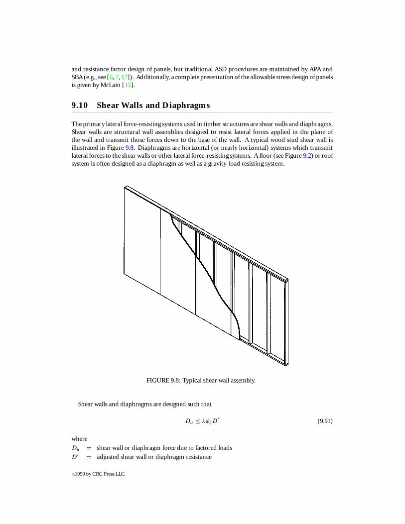
and resistance factor design of panels, but traditional ASD procedures are maintained by APA andSBA (e.g., see [6, 7, 17]). Additionally, a complete presentation of the allowable stress design of panelsis given by McLain [15].
9.10 Shear Walls and Diaphragms
The primary lateral force-resisting systems used in timber structures are shear walls and diaphragms.Shear walls are structural wall assemblies designed to resist lateral forces applied in the plane ofthe wall and transmit those forces down to the base of the wall. A typical wood stud shear wall isillustrated in Figure 9.8. Diaphragms are horizontal (or nearly horizontal) systems which transmitlateral forces to the shear walls or other lateral force-resisting systems. A floor (see Figure 9.2) or roofsystem is often designed as a diaphragm as well as a gravity-load resisting system.
FIGURE 9.8: Typical shear wall assembly.
Shear walls and diaphragms are designed such that
Du ≤ λφzD′ (9.91)
where
Du = shear wall or diaphragm force due to factored loads
D′ = adjusted shear wall or diaphragm resistance
c©1999 by CRC Press LLC
λ = time effect factorφz = resistance factor for shear walls and diaphragms = 0.65
Typically, Du and D′ are taken as the force applied and resisted, respectively, per unit length of wallor diaphragm. TheLRFDSpecification allows a simplifieddesignprocedurebasedonabeamanalogy;however, more refined and accurate analysis and design procedures are allowed if the designer wishesto use one (e.g., finite element analysis). In the beam analog, the shear wall and/or diaphragm and itsindividual components are considered as thin, deep beams with the sheathing resisting the in-planeshear and the boundary members resisting the axial forces. This equates the sheathing to the web ofan I-beam section and the boundary elements to the flanges of the I-beam. Boundary elements (e.g.,studs, sills, rim-joists, etc.) must be included at all shear wall and diaphragm perimeters and aroundinterior openings or other discontinuities.
9.10.1 Required Resistance
The required resistance of a shear wall or diaphragm, Du, comes directly from the governing factoredlateral load combination considering wind and/or seismic loads. Consideration must be made ofloads acting both along each of the structure’s principal axes and orthogonal effects. For more onthe governing load combinations and their applications, refer to the ASCE Load Standard [4].
9.10.2 Shear Wall and Diaphragm Resistance
The reference resistanceof a shearwall and/ordiaphragm is generatedoneof severalways: (1) throughexperimental tests for specific assemblies, (2) using the beam analogy, or (3) through the use of morerigorous analysis procedures (e.g., finite element analysis). To determine the resistance of a shearwall or diaphragm, consideration should be given to sheathing, framing connection resistance andspacing, sheathing capacity and configuration, blocking, and framing capacity and spacing. For manytypical assemblies (e.g., specific type and layout of structural sheathing, nail and nail spacing, andsize, species, and spacing framing members), tables are available which provide a reference resistanceper unit length (e.g., APA has numerous technical and design publications related to diaphragms andshear walls). Finally, a complete and adequate load transfer path from the shear wall or diaphragmto the supporting system must be designed.
The adjusted resistance of a shear wall and/or diaphragm, D′, is determined by adjusting thereference resistance by all the adjustment factors previously discussed in this section. In addition,a diaphragm factor, Cdi = 1.10, is used to account for the increase in resistance of nails used indiaphragms over that specified for single nail connections, recalling that no group action factor wasavailable for nail connections.
9.10.3 Design Resources
Guidelines for shear wall and diaphragm design is provided in a number of publications by APA andis actually prescribed in many model building codes, but is not covered in the NDS® . The LRFDbrings information from APA and other sources into a single document and covers shear wall anddiaphragm design; but, additional information, such as that provided by the APA, may be helpful.Additionally, a good discussion of diaphragm and shear wall design is presented by Diekmann [9].
9.11 Trusses
One of the most popular structural uses of structural lumber is in wood trusses. This includes bothtrusses designed for field construction with bolted or nailed gusset plates, as well as the pre-engineered
c©1999 by CRC Press LLC
truss. Individual members of both truss types are sized following the procedures outlined previouslyin this section for bending, tension, and compression members. The connections for pre-engineeredtrusses, however, typically involve proprietary metal plate connectors (MPC). MPCs are light gaugegalvanized steel and come in a variety of sizes, shapes, and configurations, depending on the plateproducer. The sheet stock is punched to produce projections (teeth) that are pressed into the trussmembers to form virtually any planer joint configuration required for a truss. Since MPCs areproprietary and not interchangeable, metal plate connected trusses, including the connections, aredesigned by the truss supplier per design data provided by the building designer. The responsibilitiesof each party are outlined by the WTCA [22]. The building designer is required to design the structuresuitable for supporting the truss and specifications for all truss, including orientations, spans, profiles,and minimum design loads and deflection performance. The building designer is also required toinsure adequate permanent bracing and connection of the truss(es) to the structure. The trusssupplier is required to design the truss per accepted standards (e.g., [5, 19]) to meet the requirementsset forth by building designer, temporary and permanent bracing requirements, permitted loads,and calculated deflections. A good overview of the truss industry and the design and constructionof wood truss systems is provided by Trus Joist MacMillan [18].
9.12 Curved Beams and Arches
The provisions discussed in this section are applicable to the design of glued laminated timber (as wellas solid sawn lumber and SCL); however, the advantage of the laminating process, beyond providinglarge dimensioned members, is the ability to fabricate curved and arched sections. Such membersare quite popular for medium to large structures requiring large open spans, such as churches, schoolgymnasiums, etc. Curved beams and arches of constant cross-section are discussed here; however,design provisions and procedures are available in the LRFD Specification and Manual [1, 5] forpitched and tapered curved beams and arches.
9.12.1 Curved Beams
Thedesignof curvedbeams is identical to thatof straightmembers, except that a curvature adjustmentfactor, Cc, is used to adjust the reference moment resistance and radial stresses need to be checked. Acurved beam is defined as a member with a radius of curvature of the inside face of a lamination, Rf ,defined such that Rf ≥ 100t for hardwoods and southern pine, and Rf ≥ 125t for other softwoods.
Moment Resistance
The adjusted moment resistance of a straight section was given by Equation 9.9. This basicequation is still valid for curved beams and arches, and the curvature factor, Cc, is used to modifythe published resistance of a straight, glued, laminated section of constant cross-section to accountfor curvature on the bending capacity. The curvature factor is defined by
Cc = 1 − 2000
(t
Rf
)2
(9.92)
where t = thickness of individual laminations. This factor is applied to the published referencebending strength or reference moment resistance just as any other adjustment factor. The remainderof the flexural design is then identical to that of straight beams.
c©1999 by CRC Press LLC
Radial Stresses
Radial stresses occur in curved members in the radial direction (or transverse to the bendingstresses). Tension occurs when the bending moments act to flatten the beam (or increase the radiusof curvature), and compression occurs when moments tend to increase curvature (or decrease theradius of curvature). The result is commonly a tension stress perpendicular to the grain.
To account for radial stresses induced by bending moments in curved beams, the bending resistancelimited by radial stress can be calculated using:
M ′ = 2
3RmbdF ′
r (9.93)
whereM ′ = adjusted moment resistance of the curved beam limited by radial stressRm = radius of curvature at the mid-depth of the cross-sectionb = width of the sectiond = depth of the sectionF ′
r = adjusted strength in the radial directionThe value of F ′
r depends on the type of material, whether the stress is tension or compression, andwhether radial reinforcement is provided. For example, F ′
r = adjusted radial tension (perpendicularto the grain) strength when the radial stress is tension and no reinforcement is provided; F ′
r = F ′v/3
when the radial stress is tension, Douglas-fir-Larch, Douglas-fir-South, Hem-Fir, Western Woods,or Canadian softwood species are used, and the design load is either wind or earthquake, or if rein-forcement is provided to carry the radial force; or F ′
r = adjusted radial compression (perpendicularto the grain) strength when the radial stress is compression. The radial strengths should be adjustedfor other factors, such as temperature and moisture content.
9.12.2 Arches
The primary difference between curved beams and arches is the degree of arching; that is, when theradius of curvature is small enough, arch action is induced and axial forces become an integral partof the structural resistance. Arches can be assumed when Rf < 100t for hardwoods and southernpine, and Rf < 125t for other softwoods. The two basic types of glued laminated arches are three-hinged and two-hinged arches (See Figure 9.9), and include a variety of styles such as tudor, gothic,radial, parabolic, etc. The three-hinged arch is statically determinate owing to the moment releaseat the peak. The design of three-hinged arches are, therefore, relatively straightforward and shouldconsider the combined bending moment and compression parallel to the grain along the length ofthe arch, and shear near the member ends. Two-hinged arches are statically indeterminate, and anappropriate method of analysis must be used to determine design moments, shears, and axial loadsalong the length of the arch. Once these forces and moments are determined, the design is againstraightforward and should consider the combined bending moment and compression parallel to thegrain along the length of the arch, and shear near the member ends. Two-hinged arches are slightlymore efficient than three-hinged arches; however, constructability and transportation issues oftendictate the use of three-hinged arches over two-hinged arches.
Moment Resistance
Again, the adjusted moment resistance of a straight section was given by Equation 9.9. Thisbasic equation is still valid for arches, except now, in addition to the curvature factor defined forcurved beams, the volume effect factor, CV , is for arches as follows:
1. For F ′b(1 − CV ) ≤ fc : C′
V = 1.0 (9.94)
2. For F ′b(1 − CV ) > fc : C′
V = CV + fc/F′b (9.95)
c©1999 by CRC Press LLC
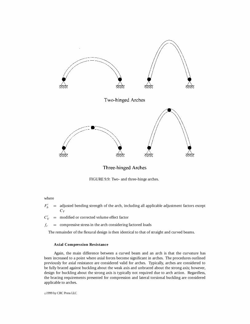
FIGURE 9.9: Two- and three-hinge arches.
where
F ′b = adjusted bending strength of the arch, including all applicable adjustment factors except
CV
C′V = modified or corrected volume effect factor
fc = compressive stress in the arch considering factored loads
The remainder of the flexural design is then identical to that of straight and curved beams.
Axial Compression Resistance
Again, the main difference between a curved beam and an arch is that the curvature hasbeen increased to a point where axial forces become significant in arches. The procedures outlinedpreviously for axial resistance are considered valid for arches. Typically, arches are considered tobe fully braced against buckling about the weak axis and unbraced about the strong axis; however,design for buckling about the strong axis is typically not required due to arch action. Regardless,the bracing requirements presented for compression and lateral torsional buckling are consideredapplicable to arches.
c©1999 by CRC Press LLC
Interaction Equation for Arches
The interaction of bending moments and axial forces is accounted for in the same manner aspresented for straight columns. However, since arches are often fully braced against buckling in theweak direction, the factored moment need not be magnified. Therefore, the interaction equationgiven by Equation 9.40 reduces to
(Pu
λφcP ′c
)2
+ Mbx
λφbM ′x
≤ 1.0 (9.96)
for arches where Pu = factored axial load; P ′c = adjusted axial compression resistance; Mbx =
factored moment about the strong axis; M ′x = adjusted moment capacity about the strong axis; λ =
time effect factor; and φc and φb = resistance factors for axial compression and bending, respectively.
Radial Stresses
Due to the arch action and geometry, radial stresses are induced in arches and must be checked.The procedure to determine a moment resistance is limited by radial stress and is identical to thatpresented for curved beams.
9.12.3 Design Resources
The NDS® [2] provides design procedures essentially identical to that used in the LRFD Speci-fication [5]. A good overview of glued laminated curved beam and arch deign is provided byKasaguma [14]. Additional and more detailed design information and guidelines for curved, pitched,and tapered beams and arches are provide by the American Institute of Timber Construction (AITC)in numerous design aids as well as in the Timber Construction Manual [3].
9.13 Serviceability Considerations
Previous discussion in this section has focused entirely on strength design (i.e., strength resistance),which is intended to insure adequate safeguard against structural collapse. As with all types of struc-ture, the serviceability performance of a timber structure is critical, not from a safety viewpoint, butrather for occupant satisfaction. Structural serviceability considerations (e.g., deflections, vibrations,etc.) often govern the design of a timber structure. Additionally, the lack of designer attention todetailing, especially detailing which protects wood from moisture, ultraviolet, and/or insect attack,often leads to performance and even structural problems.
9.13.1 Deflections
The most common serviceability design check is to compare the static (short-term) deflection result-ing from service loads to some limiting quantity. Historically, this limit has been span/360 for floorssubjected to a full uniform floor live load and span/240 for roof members subjected to roof live load.Model and local building codes may delineate more specific limits for static deflections.
To calculate the deflection used to compare to the limiting value, the appropriate design load,span, and material properties must be used. The following unfactored load combinations are usedto determine the deflection:
D + L (9.97)
D + 0.5S (9.98)
c©1999 by CRC Press LLC
where D, L, and S are the nominal design dead, live, and snow loads. The design span is taken as theclear span plus one-half the required bearing length at each support, and the adjusted modulus ofelasticity, E′, is used for serviceability calculations. The reference modulus of elasticity, E, for lumberis a mean value and includes a 3% reduction to account for shear effects; therefore, if shear deflectionsare calculated separately, it is appropriate to increase the reference value by 3%. For glued laminatedtimber, E includes a 5% decrease for shear. In some critical applications, it may be appropriate touse a fifth-percentile value of E rather than a mean value. In this case, E05 can be determined aspresented in Equation 9.14.
In addition to short-term deflections, the effects of creep must be considered in the design of timberstructures. The LRFD suggests using the following load combination when considering creep:
D + 0.5L (9.99)
where it is assumed approximately half the live load has a sustained component which may attributeto creep. In addition, the LRFD suggests increasing the calculated deflection (using the above loadcombination) by 50 to 100%. A creep multiplier of 1.5 is suggested for glued laminated timberand seasoned sawn lumber, and a factor of 2.0 is used for unseasoned lumber. Recent researchby Fridley [12] and Philpot et al. [16] provide a more complete treatment of creep for design,including various creep factors dependent on the load combination and reference period (time)under consideration. Regardless, the multiplier is used to magnify the calculated elastic deflectionto account for creep effects.
9.13.2 Vibrations
Current serviceability design of wood joist floor systems is based on static deflection checks asdiscussed previously. In the U.S., there are no set guidelines to account for floor vibrations. Thisoften leads to objectionable vibrations due to occupant loading. With the use of I-joists and othernew, lightweight products, increasing spans can be achieved along with a decrease in the weight of thefloor. These aspects tend to cause an increase in the number of complaints about annoying vibrations.Manufactures of proprietary products (e.g., wood I-joists) have moved toward providing span tablesfor serviceability which address vibrations. Often, this is as simple as limiting deflection to span/480rather than span/360. A number of more rigorous methods for vibration design have been presentedin the literature (e.g., see Kalkert et al. [13]). The LRFD, in its commentary, reviews several of theseapproaches, but makes no formal recommendation as to a preferred method of analysis or design.
9.13.3 NDS® Provisions
The LRFD adopted the same serviceability deflection design methodology as that provided by NDS®with respect to static (or short-term) and creep (or long-term) deflection. Being an ASD specifi-cation, the NDS® does not, however, provide separate load combinations for serviceability design.Rather, the same working/service loads are used for strength considerations. The NDS® offers norecommendations for vibrations either.
9.13.4 Non-Structural Performance
Often out of the control of the structural designer, the misconstruction and mis-installation of wood,wood materials, and building envelops can effectively shorten the life of a timber structure. Frommoisture intrusion to insect attack and decay, wood must be protected, or at least guarded fromdetrimental environments and conditions. A complete presentation of detailing to avoid problems isbeyond the scope of this section, but Dost and Botsai [10] provide a comprehensive guide to detailing
c©1999 by CRC Press LLC
timber structures for performance with specific attention to protecting the structure and wood-basedmaterials from deterioration. With proper detailing, and attention to details, a timber structure canenjoy a long and useful life, even in exposed environments.
9.14 Defining Terms
Dimensioned lumber: Solid members from 38 to 89 mm in thickness and 33 mm or greater inwidth (depth).
Dowel-type fasteners: Fasteners such as bolts, lag screws, wood screws, nails, spikes, etc.
Dry service: Structures wherein the maximum equilibrium moisture content of the wood doesnot exceed 19%.
Equilibrium moisture content: The moisture content at which wood neither gains moisturefrom nor loses moisture to the surrounding air.
Fiber saturation point: The point at which free water in the cell cavities is completely evapo-rated, but the cell walls are still saturated.
Glued laminated timber (Glulam): Acompositewoodmemberwithwood laminationsbondedtogether with adhesive and with the grain of all laminations oriented parallel longitudi-nally.
Grade: Classification of structural wood products with reference to strengh and use.
Green lumber: Lumber that has a moisture content exceeding 19%.
I-joists: Prefabricated manufactured members using solid or composite lumber flanges andstructural panel webs.
Laminated veneer lumber (LVL): Composite lumber products comprised of wood veneersheets oriented with the grain parallel to the lenght of the member.
Load-duration (time-effect): The strenght of wood is a function of the duration and/or rate theload is applied to the member. That is, a member can resist higher magnitude loads forshorter durations or, stated differently, the longer a load is applied, the less able a woodmember is to support that load.
Machine-evaluated lumber (MEL): Lumber non-destructively evaluated and classified intostrength classifications.
Machine stress-rated (MSR) lumber: Lumber non-destructively evaluated and assigned bend-ing strength and modulus of elasticity design values.
Moisture content: The amount of moisture present in wood defined by the weight of watercontained in the wood as a percentage of the weight of the oven-dry wood.
Oriented strandboard (OSB): Structural panel comprised of thin flakes oriented in cross-aligned layers.
Parallel strand lumber (PSL): Composite lumberproducts comprisedofwood strandsorientedwith the grain parallel to the lenght of the member.
Plywood: Structural panel comprised of thin veneers oriented in cross-aligned layers.
Pressure-treated wood: Products treated to make them more resistant to biological attack orenvironmental conditions.
Repetitive member systems: A system such as a floor, roof, or wall assembly which consists ofclosely spaced parallel members exhibiting load sharing among the members.
Seasoned lumber: Lumber that has been dried to a maximum of 19% moisture content.
Shear plate: Circular plate embedded between two wood members or a wood member and asteel side plate with a single bolt to transfer shear from the wood to the bolt.
c©1999 by CRC Press LLC
Sheathing: Lumber or structural panel attached to framing members, typically forming a wall,floor, or roof.
Span rating: Index used for structural panels identifying the maximum spacing of supportingframing members for roof, floor, and/or wall applications.
Split ring: Metal ring embedded into adjacent wood members to transmit shear force betweenthem.
Stressed skin panel: Type of construction wherein the framing members and sheathing act asa composite system to resist load.
Structural composite lumber (SCL): Composite lumber products typically comprised of woodstrands or veneers oriented with the grain parallel to the length of the member.
Stud: Vertical framing member used in walls, typically 2 × 4 and 2 × 6.
Timbers: Lumber of greater than 114 mm in its least dimension.
Truss-plate connectors: Light gage steel plates with punched teeth typically used in prefabri-cated wood truss systems.
Visually graded lumber: Lumber graded visually and assigned engineering design values.
Wet service: Structures wherein in the maximum equilibrium moisture content of the woodexceeds 19%.
References
[1] American Forest & Paper Association (AF&PA). 1996. Manual of Wood Construction: Loadand Resistance Factor Design, AF&PA, Washington, D.C.
[2] American Forest & Paper Association (AF&PA). 1991. National Design Specification for WoodConstruction and Supplement, AF&PA, Washington, D.C.
[3] American Institute of Timber Construction (AITC). 1994. Timber Construction Manual, 4thed., John Wiley & Sons, New York.
[4] American Society of Civil Engineers (ASCE). 1996. Minimum Design Loads for Buildings andOther Structures, ASCE 7-75, ASCE, New York.
[5] American Society of Civil Engineers (ASCE). 1996. Load and Resistance Factor Design (LRFD)for Engineered Wood Construction, AF&PA/ASCE 16-95, ASCE, New York.
[6] APA—The Engineered Wood Association (APA). 1989. The Plywood Design Specification andSupplements, APA, Tacoma, WA.
[7] APA—The Engineered Wood Association (APA). 1993. Design/Construction Guide, Residen-tial and Commercial Construction, APA, Tacoma, WA.
[8] Bodig, J. andJayne, B.1982.Mechanics ofWoodandWoodComposites,VanNostrandReinhold,New York.
[9] Diekmann, E.F. 1995. Diaphragms and Shearwalls, in Wood Engineering and ConstructionHandbook, 2nd ed., K.F. Faherty and T.G. Williamson, Eds., McGraw Hill, New York.
[10] Dost, W.A. and Botsai, E.E. 1990. Wood: Detailing for Performance, GRDA Publications, MillValley, CA.
[11] Freas, A.D. 1995. Wood Properties, in Wood Engineering and Construction Handbook, 2nded., K.F. Faherty and T.G. Williamson, Eds., McGraw-Hill, New York.
[12] Fridley, K.J. 1992. Designing for Creep in Wood Structures, Forest Products J., 42(3):23-28.[13] Kalkert, R.E., Dolan, J.D., and Woeste, F.E. 1993. The Current Status of Analysis and Design
for Annoying Wooden Floor Vibrations, Wood Fiber Sci., 25(3):305-314.[14] Kasaguma, R.K. 1995. Arches and Domes, in Wood Engineering and Construction Handbook,
2nd ed., K.F. Faherty and T.G. Williamson, Eds., McGraw-Hill, New York.
c©1999 by CRC Press LLC
[15] McLain, T.E. 1995. Structural-Use Panels, in Wood Engineering and Construction Handbook,2nd ed., K.F. Faherty and T.G. Williamson, Eds., McGraw-Hill, New York.
[16] Philpot, T.A., Rosowsky, D.V., and Fridley, K.J. 1993. Serviceability Design in LRFD for Wood,J. Structural Eng., 119(12):3649-3667.
[17] Structural Board Association (SBA). 1995. SpecRite: Industrial, Residential, Codes and Grades,and Specifications on Disk. SBA, Onterio, Canada.
[18] Trus Joist MacMillan. 1995. Trusses, in Wood Engineering and Construction Handbook, 2nded., K.F. Faherty and T.G. Williamson, Eds., McGraw-Hill, New York.
[19] Truss Plate Institute (TPI). 1995. National Design Specification for Metal Plate ConnectedWood Truss Construction, ANSI/TPI 1-1995, TPI, Madison, WI.
[20] United States Department of Agriculture (USDA). 1987. Wood Handbook: Wood as an En-gineering Material, Agriculture Handbook 72, Forest Products Laboratory, USDA, Madison,WI.
[21] United States Department of Commerce. 1992. Performance Standard for Wood-BasedStructural-Use Panels, PS 2-92, Washington D.C.
[22] WoodTrussCouncil ofAmerica (WTCA). 1995.StandardResponsibilities in theDesignProcessInvolving Metal Plate Connected Wood Trusses, WTCA 1-1995, WTCA, Madison, WI.
Further Reading
[1] Breyer, D. 1993. Design of Wood Structures, 3rd ed., McGraw-Hill, New York.[2] Faherty, K. and Williamson, T. 1995. Wood Engineering and Construction Handbook, 2nd ed.,
McGraw-Hill, New York.[3] Gurfinkle, G. 1981. Wood Engineering, 2nd ed., Kendall/Hunt Publishing (available from
Southern Forest Products Association, Box 524468, New Orleans, LA 70152).[4] Hoyle, R. and Woeste, F. Wood Technology in the Design of Structures, 5th ed., Iowa State
University Press, Ames, IA.[5] Madsen, B. 1992. Structural Behaviour of Timber, Timber Engineering Ltd., N. Vancouver,
British Columbia, Canada.[6] Ritter, M. 1990. Timber Bridges: Design, Construction, Inspection, and Maintenance, United
States Department of Agriculture, Forest Service, Washington, D.C.[7] Somayaji, S. 1990. Structural Wood Design, West Publishing Company, New York.[8] Stahlnaker, J. and Harris, E. 1989. Structural Design in Wood, Van Nostrand Reinhold, New
York.[9] Western Woods Use Book, 4th ed., 1996. Western Wood Products Association, Portland, OR.
[10] Wood Design Manual. 1990. Canadian Wood Council, Ottawa, Canada.[11] Wood as a Structural Material. 1982. Clark C. Heritage Memorial Series on Wood, Vol. 2,
Pennsylvania State University, University Park, PA.
c©1999 by CRC Press LLC