friction in internal combustion engines - bme -...
TRANSCRIPT

Copyright: Prof. Dr.-Ing. W. Hannibal, Fachhochschule Südwestfalen, University of Applied Science, Iserlohn, Germany, contact: [email protected]. 1
Prof. Dr.-Ing. Wilhelm Hannibal,
Fachhochschule Südwestfalen,
University of Applied Science,
Iserlohn, Germany
Friction in Internal Combustion Engines
Lecture at the
Budapest University
of Technology and EconomicsNovember 18, 2010
Mean effective pressure pme [bar]
Mean f
riction p
ressure
pm
r[b
ar]

Copyright: Prof. Dr.-Ing. W. Hannibal, Fachhochschule Südwestfalen, University of Applied Science, Iserlohn, Germany, contact: [email protected]
Fig. 2
1 Introduction
2 Basic Theoretical Views of Friction and Lubrication
4 Influence of Friction on the Fuel Consumption
3 Methods for Measuring of Friction at Internal Combustion Engines
5 Friction Behaviour of Combustion Engines Already Built
7 Friction of the Engine Block Components
6 Friction of the Valve Train Components
9 Thermo Management
11 Reduction of Friction Through Variable Valve Train
Presentation Outline
10 Reduction of Idle Speed
12 Trends In The Engine Development to Reduce Friction
8 Friction of the Auxiliaries
13 Summary / Outlook

Copyright: Prof. Dr.-Ing. W. Hannibal, Fachhochschule Südwestfalen, University of Applied Science, Iserlohn, Germany, contact: [email protected]
• Optimization of the burning process
„Better Efficiency“
1 Introduction
Measures to Reduce Fuel Consumption on Combustion Engines
• Reduction of the engine´s friction
• Reduction of pumping losses
Source: BMW

Copyright: Prof. Dr.-Ing. W. Hannibal, Fachhochschule Südwestfalen, University of Applied Science, Iserlohn, Germany, contact: [email protected]
Fig. 4
1 Introduction
2 Basic Theoretical Views of Friction and Lubrication
4 Influence of Friction on the Fuel Consumption
3 Methods for Measuring of Friction at Internal Combustion Engines
5 Friction Behaviour of Combustion Engines Already Built
7 Friction of the Engine Block Components
6 Friction of the Valve Train Components
9 Thermo Management
11 Reduction of Friction Through Variable Valve Train
Presentation Outline
10 Reduction of Idle Speed
12 Trends In The Engine Development to Reduce Friction
8 Friction of the Auxiliaries
13 Summary / Outlook

Fig. 5Copyright: Prof. Dr.-Ing. W. Hannibal, Fachhochschule Südwestfalen, University of Applied Science, Iserlohn, Germany, contact: [email protected]
The useful power at the output shaft of internal combustion
engines (effective power Pe) is lower than the internal power
at the pistons (indicated power Pi).
The difference is referred to as the friction loss Pr.
Pr = Pi - Pe
2 Basic Theoretical Views of Friction and Lubrication
Definition of Friction

Fig. 6Copyright: Prof. Dr.-Ing. W. Hannibal, Fachhochschule Südwestfalen, University of Applied Science, Iserlohn, Germany, contact: [email protected]
The friction power is the sum of the friction of all engine
components like piston friction, valve train friction, pump friction
etc..
To compare different engines in their efficiency the friction is
summarized in the mean friction pressure pmr.
2 Basic Theoretical Views of Friction and Lubrication
Definition of Friction

Fig. 7Copyright: Prof. Dr.-Ing. W. Hannibal, Fachhochschule Südwestfalen, University of Applied Science, Iserlohn, Germany, contact: [email protected]
2 Basic Theoretical Views of Friction and Lubrication
Components that Cause Friction
The friction of a complete engine includes the friction losses or drive powers of the
individual engine´s components:
An engine consisting of:
• Crankshaft main bearing with radial shaft sealing rings
• Connection rod bearings and piston group (pistons, piston rings and piston pins)
• Any mass balancing systems
Valve train and timing gear
Auxiliaries, such as:
• Oil pump, possibly with oil pump drive
• Coolant pump
• Alternator
• Fuel injection pump
• Radiator fan
• Vacuum pump
• Air conditioning Compressor
• Power steering pump
• Air CompressorSource: Basshuysen, [2]

Fig. 8Copyright: Prof. Dr.-Ing. W. Hannibal, Fachhochschule Südwestfalen, University of Applied Science, Iserlohn, Germany, contact: [email protected]
2 Basic Theoretical Views of Friction and Lubrication
Friction States
Depending on lubrication prevailing at the various friction points in the
engine, different friction states occur. The most important are:
• Solid friction (Coulomb‘s friction)Friction between solids without fluid intermediate layer.
• Boundary frictionFriction between solids with an applied solid lubricant layer without a fluid
intermediate layer
• Mixed frictionFluid friction and solid friction or boundary friction occur simultaneously; the
lubricant layer does not completely separate the two friction layers from one
another, and a certain contact occurs.
• Fluid friction (hydrodynamic friction)A liquid (or gaseous) substance between the two friction layers completely
separates' the two from one another. In the internal combustion engine, the
movement of the friction surfaces against one another creates the
hydrodynamic supporting effect of the intermediate substance.
Source: Basshuysen, [2]

Copyright: Prof. Dr.-Ing. W. Hannibal, Fachhochschule Südwestfalen, University of Applied Science, Iserlohn, Germany, contact: [email protected]. 9
2 Basic Theoretical Views of Friction and Lubrication
Stribeck Curve
Co
effic
ien
t of
fric
tion
μ
Starting friction
ν = const.
Boundary friciton
Mixed frictionLiquid friction
Breakaway point
Lower
operating limit
Upper
operating limit
Sliding speed v
- - - - - - - Liquid friction
- - - - - Solid friction
Source: Affenzeller, [3]

Fig. 10Copyright: Prof. Dr.-Ing. W. Hannibal, Fachhochschule Südwestfalen, University of Applied Science, Iserlohn, Germany, contact: [email protected]
2 Basic Theoretical Views of Friction and Lubrication
The Level of Temperatures at Combustion Engines
component s temperature is one of the most friction influencing parameters
180 to 300 C
to
to
to
180 to 300 C
115 to 185 C
80 to 150 CSource: Grebe, [4]

Fig. 11Copyright: Prof. Dr.-Ing. W. Hannibal, Fachhochschule Südwestfalen, University of Applied Science, Iserlohn, Germany, contact: [email protected]
2 Basic Theoretical Views of Friction and Lubrication
“Ubbelohe Diagram”
Temperature [ C]
Kin
em
atic v
iscosity in
[m
m2
/ s]
Engine oil

Fig. 12Copyright: Prof. Dr.-Ing. W. Hannibal, Fachhochschule Südwestfalen, University of Applied Science, Iserlohn, Germany, contact: [email protected]
2 Basic Theoretical Views of Friction and Lubrication
Temperature Scope of Engine´s Oil Quality
Temperature
in C Source: Grebe, [4]

Fig. 13Copyright: Prof. Dr.-Ing. W. Hannibal, Fachhochschule Südwestfalen, University of Applied Science, Iserlohn, Germany, contact: [email protected]
2 Basic Theoretical Views of Friction and Lubrication
The Engine´s Oil Circuit
Temperature-
sensor
Lubrication
(camshaft)oil pressure sensor
Oil pump
Oil cooler
With cooling
Without cooling
Pressure relief valve
(opens at 5.4 bar) Pressure relief valve
(opens at 8 bar)
Oil pressure and
oil temperature
gauge
Ventilation
from engine to
fuel tank
Ventilation to air filter
Storing
tank
Full flow filter
Drills
Oil strainer
Plain
oil pan
Oil pump for the recirculation
Source: Grebe, [4]
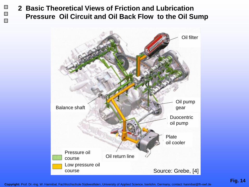
Fig. 14Copyright: Prof. Dr.-Ing. W. Hannibal, Fachhochschule Südwestfalen, University of Applied Science, Iserlohn, Germany, contact: [email protected]
2 Basic Theoretical Views of Friction and Lubrication
Pressure Oil Circuit and Oil Back Flow to the Oil Sump
Balance shaft
Oil pump
gear
Duocentric
oil pump
Plate
oil cooler
Oil return line
Oil filter
Pressure oil
course
Low pressure oil
course Source: Grebe, [4]

Fig. 15Copyright: Prof. Dr.-Ing. W. Hannibal, Fachhochschule Südwestfalen, University of Applied Science, Iserlohn, Germany, contact: [email protected]
2 Basic Theoretical Views of Friction and Lubrication
Hydro Dynamical Lubrication
Tightened
gap

Fig. 16Copyright: Prof. Dr.-Ing. W. Hannibal, Fachhochschule Südwestfalen, University of Applied Science, Iserlohn, Germany, contact: [email protected]
2 Basic Theoretical Views of Friction and Lubrication
Shaft Position over Shaft Speed
speed = 0 low speed high speed speed = ∞

Fig. 17Copyright: Prof. Dr.-Ing. W. Hannibal, Fachhochschule Südwestfalen, University of Applied Science, Iserlohn, Germany, contact: [email protected]
a) Dry friction a) Mixed friction c) Liquid friction
Liquid
pressure
Liquid
friction
Dry
friction
Lubrica-
tion oil
bearing
forceBearing
force
Lubrica-
tion oil
Standstill Low peripheral speed High peripheral speedBearing
Bearing
journal
2 Basic Theoretical Views of Friction and Lubrication
Shaft Position Depending on Friction Status

Fig. 18Copyright: Prof. Dr.-Ing. W. Hannibal, Fachhochschule Südwestfalen, University of Applied Science, Iserlohn, Germany, contact: [email protected]
2 Basic Theoretical Views of Friction and Lubrication
Influence of the Shaft Bending on the Bearing Pressure

Fig. 19Copyright: Prof. Dr.-Ing. W. Hannibal, Fachhochschule Südwestfalen, University of Applied Science, Iserlohn, Germany, contact: [email protected]
2 Basic Theoretical Views of Friction and Lubrication
Influence of the Bending Geometry on the Bearing Pressure

Copyright: Prof. Dr.-Ing. W. Hannibal, Fachhochschule Südwestfalen, University of Applied Science, Iserlohn, Germany, contact: [email protected]
Fig. 20
1 Introduction
2 Basic Theoretical Views of Friction and Lubrication
4 Influence of Friction on the Fuel Consumption
3 Methods for Measuring of Friction at Internal Combustion Engines
5 Friction Behaviour of Combustion Engines Already Built
7 Friction of the Engine Block Components
6 Friction of the Valve Train Components
9 Thermo Management
11 Reduction of Friction Through Variable Valve Train
Presentation Outline
10 Reduction of Idle Speed
12 Trends In The Engine Development to Reduce Friction
8 Friction of the Auxiliaries
13 Summary / Outlook
Copyright: Prof. Dr.-Ing. W. Hannibal, Fachhochschule Südwestfalen, University of Applied Science, Iserlohn, Germany, contact: [email protected]. 21
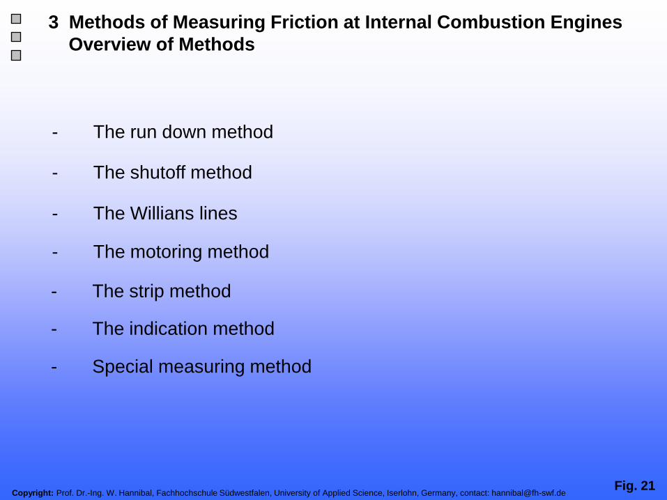
- The run down method
- The shutoff method
- The motoring method
- The Willians lines
- The strip method
- Special measuring method
- The indication method
3 Methods of Measuring Friction at Internal Combustion Engines
Overview of Methods

Copyright: Prof. Dr.-Ing. W. Hannibal, Fachhochschule Südwestfalen, University of Applied Science, Iserlohn, Germany, contact: [email protected]. 22
3 Methods of Measuring Friction at Internal Combustion Engines
The Run Down Method
Here the engine is switched off after stabilization at an operating
point, and the change in speed is measured as a function of
time. The friction moment or mean friction pressure is then
calculated using the moments of inertia of the moving masses.

Copyright: Prof. Dr.-Ing. W. Hannibal, Fachhochschule Südwestfalen, University of Applied Science, Iserlohn, Germany, contact: [email protected]. 23
3 Methods of Measuring Friction at Internal Combustion Engines
The Shutoff Method
On multiple-cylinder engines, the fuel supply to one of the cylinder
is shut off, and this cylinder is then dragged along by the other
working cylinders.
The friction loss can be determined from the change in effective
engine power before and after the fuel shutoff.

Copyright: Prof. Dr.-Ing. W. Hannibal, Fachhochschule Südwestfalen, University of Applied Science, Iserlohn, Germany, contact: [email protected]. 24
3 Methods of Measuring Friction at Internal Combustion Engines
The Willians Lines
The fuel consumption of an engine is plotted on the Y-axis against
the mean effective pressure pme for various engine speeds.
The intersections with the negative pme axis are then determined
by linear extrapolation of the values down to fuel consumption
zero; these can be roughly regarded as the mean friction pressure
at the respective engine speeds.

Copyright: Prof. Dr.-Ing. W. Hannibal, Fachhochschule Südwestfalen, University of Applied Science, Iserlohn, Germany, contact: [email protected]. 25
3 Methods of Measuring Friction at Internal Combustion Engines
The Motoring Method
The engine is motored on a
test rig by an external motor.
The motoring power
required to drive the engine
is regarded as the friction
loss. With this method either
the engine can be motored
at operating temperature
and measured immediately
after shutting of the fuel
supply or it can be
conditioned via external
thermostat installations.

Copyright: Prof. Dr.-Ing. W. Hannibal, Fachhochschule Südwestfalen, University of Applied Science, Iserlohn, Germany, contact: [email protected]. 26
3 Methods of Measuring Friction at Internal Combustion Engines
The Strip Method
Strip measurement is a special form of motoring that is used to
measure the friction losses of the various engine components, such
as, the friction of the engine, the valve train, and the auxiliary drives.
The designation derives from the method where the engine is
dismantled (stripped) step by step on a motoring test rig.
The friction losses of the individual components are determined from
the difference between the measured values with and without these
components. The total friction of the engine is obtained by addition of
the values for the individual components.

Copyright: Prof. Dr.-Ing. W. Hannibal, Fachhochschule Südwestfalen, University of Applied Science, Iserlohn, Germany, contact: [email protected]. 27
3 Methods of Measuring Friction at Internal Combustion Engines
The Indication Method
This method can be used to
determine the friction of an
engine in motoring mode.
Integration of the measured
cylinder pressure over a
working cycle gives the
indicated work Wi which
referred to the swept volume,
gives the indicated mean
pressure pmi. If the mean
effective pressure pme
calculated from the torque
measured at the drive shaft is
subtracted from this, we
obtain the mean friction
pressure pmr.

Fig. 28Copyright: Prof. Dr.-Ing. W. Hannibal, Fachhochschule Südwestfalen, University of Applied Science, Iserlohn, Germany, contact: [email protected]
3 Methods of Measuring Friction at Internal Combustion Engines
The Cylinder Pressure Transducer
Source: Kistler

Fig. 29Copyright: Prof. Dr.-Ing. W. Hannibal, Fachhochschule Südwestfalen, University of Applied Science, Iserlohn, Germany, contact: [email protected]
3 Methods of Measuring Friction at Internal Combustion Engines
The Cylinder Pressure Indication; Charge Amplifier
Source: Kistler

Fig. 30Copyright: Prof. Dr.-Ing. W. Hannibal, Fachhochschule Südwestfalen, University of Applied Science, Iserlohn, Germany, contact: [email protected]
3 Methods of Measuring Friction at Internal Combustion Engines
The Cylinder Pressure Indication; Data Post Processing
Source: Kistler

Fig. 31Copyright: Prof. Dr.-Ing. W. Hannibal, Fachhochschule Südwestfalen, University of Applied Science, Iserlohn, Germany, contact: [email protected]
3 Methods of Measuring Friction at Internal Combustion Engines
Example of Cylinder Pressure Measurement Equipment
Gas meter
Oscillo
-scope
Air
Exhaust
silencer
Oil coolerExternal
oil pump
Light barrier
Voltmeter
Engine
speed
measuring
Consumption measuring
Heater
Radiator Oil filterControl pressure Generator Torque measuring
P1- meter
Heater Oil pressureMetering point
Return flow
cooling
Filter
TankElectric fuel pump
Flow divider
Precleaner Air
meter
U- bend mano-
meter
Fuel injectors
Thermocouple
Pressure sensor
Crank-
shaft
mark
Calming tank
Source: Hannibal, [1]
Air filter and flow sensor
plate

Fig. 32Copyright: Prof. Dr.-Ing. W. Hannibal, Fachhochschule Südwestfalen, University of Applied Science, Iserlohn, Germany, contact: [email protected]
3 Methods of Measuring Friction at Internal Combustion Engines
pmi Defect Because of an Incorrect TDC Trigger Signal
After TDC Before TDCTrigger pulse
Source: Hannibal, [1]

Fig. 33Copyright: Prof. Dr.-Ing. W. Hannibal, Fachhochschule Südwestfalen, University of Applied Science, Iserlohn, Germany, contact: [email protected]
3 Methods of Measuring Friction at Internal Combustion Engines
The Cylinder Pressure Indication; Piston Position Adjustment
Digital VoltmeterBulb PI Meter
Oscilloscope
Engine block
Piston Stroke Measurement
Crank shaft mark
Groove disk
Phototransistor
b. TDC TDC a.TDC
Source: Hannibal, [1]
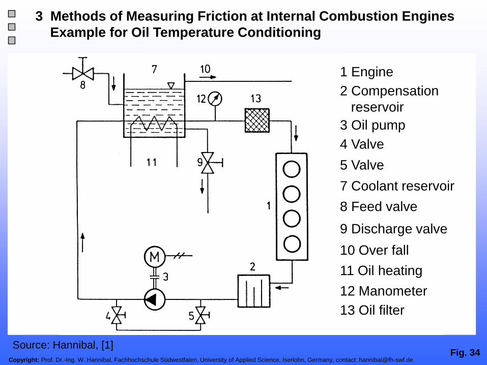
Fig. 34Copyright: Prof. Dr.-Ing. W. Hannibal, Fachhochschule Südwestfalen, University of Applied Science, Iserlohn, Germany, contact: [email protected]
3 Methods of Measuring Friction at Internal Combustion Engines
Example for Oil Temperature Conditioning
2 Compensation
reservoir
1 Engine
3 Oil pump
4 Valve
5 Valve
7 Coolant reservoir
8 Feed valve
9 Discharge valve
10 Over fall
11 Oil heating
12 Manometer
13 Oil filter
Source: Hannibal, [1]

Fig. 35Copyright: Prof. Dr.-Ing. W. Hannibal, Fachhochschule Südwestfalen, University of Applied Science, Iserlohn, Germany, contact: [email protected]
3 Methods of Measuring Friction at Internal Combustion Engines
Example for Water Temperature Conditioning
1 Engine
2 Coolant reservoir
3 Feed valve
4 Discharge valve
5 Over fall
6 Coolant heating
7 Water pump
Source: Hannibal, [1]

Copyright: Prof. Dr.-Ing. W. Hannibal, Fachhochschule Südwestfalen, University of Applied Science, Iserlohn, Germany, contact: [email protected]. 36
3 Methods of Measuring Friction at Internal Combustion Engines
Special Measuring Method
Apart from the friction measuring methods described above,
there are a large number of other methods for determining,
for example, the friction of individual components during
operation. Torque measuring flanges can be used to carry
out measurements on components driven by shafts. For the
piston group there are various facilities for measuring the
piston frictional force.

Copyright: Prof. Dr.-Ing. W. Hannibal, Fachhochschule Südwestfalen, University of Applied Science, Iserlohn, Germany, contact: [email protected]. 37
3 Methods of Measuring Friction at Internal Combustion Engines
Comparison of the Individual Friction Measurement Methods
Source: Basshuysen, [2]

Copyright: Prof. Dr.-Ing. W. Hannibal, Fachhochschule Südwestfalen, University of Applied Science, Iserlohn, Germany, contact: [email protected]
Fig. 38
1 Introduction
2 Basic Theoretical Views of Friction and Lubrication
4 Influence of Friction on the Fuel Consumption
3 Methods for Measuring of Friction at Internal Combustion Engines
5 Friction Behaviour of Combustion Engines Already Built
7 Friction of the Engine Block Components
6 Friction of the Valve Train Components
9 Thermo Management
11 Reduction of Friction Through Variable Valve Train
Presentation Outline
10 Reduction of Idle Speed
12 Trends In The Engine Development to Reduce Friction
8 Friction of the Auxiliaries
13 Summary / Outlook

Fig. 39Copyright: Prof. Dr.-Ing. W. Hannibal, Fachhochschule Südwestfalen, University of Applied Science, Iserlohn, Germany, contact: [email protected]
The mechanical efficiency ηm of an internal combustion engine
is defined as the ratio of mean effective pressure pme to mean
indicated pressure pmi.
To compare different engines in their efficiency the friction is
summarized in the mean effective friction pressure pmr.
At an engine speed of 2000 rpm pmr has values between 0.5
and 1.4 bar including injection pump and all engine components.
4 Influence of Friction on the Fuel Consumption
Comparison between Diesel and Spark Ignition Engines

Copyright: Prof. Dr.-Ing. W. Hannibal, Fachhochschule Südwestfalen, University of Applied Science, Iserlohn, Germany, contact: [email protected]. 40
4 Influence of Friction on the Fuel Consumption
Comparison between Diesel and Spark Ignition Engines
Complete engine
Motor, valve train
loaded oil pump,
Loaded water pump
Unloaded alternator
Motored, full load
Oil: 15W40
Oil/Coolant temperature: 90 C
Spark ignition engine
Diesel engine (direct injection)
Mean f
riction p
ressure
pm
r[b
ar]
Engine speed [1/min] Source: Koch, [5]
Copyright: Prof. Dr.-Ing. W. Hannibal, Fachhochschule Südwestfalen, University of Applied Science, Iserlohn, Germany, contact: [email protected]. 41
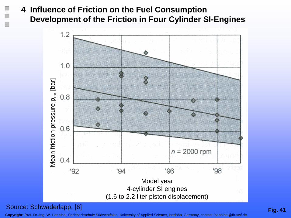
4 Influence of Friction on the Fuel Consumption
Development of the Friction in Four Cylinder SI-Engines
Mean f
riction p
ressure
pm
r[b
ar]
Model year
4-cylinder SI engines
(1.6 to 2.2 liter piston displacement)
Source: Schwaderlapp, [6]

Copyright: Prof. Dr.-Ing. W. Hannibal, Fachhochschule Südwestfalen, University of Applied Science, Iserlohn, Germany, contact: [email protected]. 42
4 Influence of Friction on the Fuel Consumption
Comparison between Diesel and Spark Ignition Engines
Diesel engine
Spark
ignition
engine
Re
du
ctio
n o
f fu
el co
nsu
mp
tio
n
Reduction of friction
Source: Koch, [7]

Copyright: Prof. Dr.-Ing. W. Hannibal, Fachhochschule Südwestfalen, University of Applied Science, Iserlohn, Germany, contact: [email protected]. 43
4 Influence of Friction on the Fuel Consumption
Percentages of Friction losses in the Engine Characteristic Map
Engine speed [1/min]
Po
we
r [%
]
Source: FEV

Copyright: Prof. Dr.-Ing. W. Hannibal, Fachhochschule Südwestfalen, University of Applied Science, Iserlohn, Germany, contact: [email protected]
Fig. 44
1 Introduction
2 Basic Theoretical Views of Friction and Lubrication
4 Influence of Friction on the Fuel Consumption
3 Methods for Measuring of Friction at Internal Combustion Engines
5 Friction Behaviour of Combustion Engines Already Built
7 Friction of the Engine Block Components
6 Friction of the Valve Train Components
9 Thermo Management
11 Reduction of Friction Through Variable Valve Train
Presentation Outline
10 Reduction of Idle Speed
12 Trends In The Engine Development to Reduce Friction
8 Friction of the Auxiliaries
13 Summary / Outlook

Copyright: Prof. Dr.-Ing. W. Hannibal, Fachhochschule Südwestfalen, University of Applied Science, Iserlohn, Germany, contact: [email protected]. 45
5 Friction Behaviour of Combustion Engines Already Built
Friction Breakdown of a Modern Car SI Engine
Source: Koch, [7]
Mean f
riciton
pre
ssure
pm
r[b
ar]
Mean f
riction p
ressure
pm
r[b
ar]
Engine speed [1/min]
Water pump
and alternator
Oil pump
Valve train
Pistons and piston rods
Crankshaft
Oil: SAE 15W40
Oil/coolant
temperature: 90 C

Fig. 46Copyright: Prof. Dr.-Ing. W. Hannibal, Fachhochschule Südwestfalen, University of Applied Science, Iserlohn, Germany, contact: [email protected]
auxiliaries
valve train
piston group
crank shaft
Perc
en
tag
e
[%
]
Engine speed [rpm]
5 Friction Behaviour of Combustion Engines Already Built
Percentage Breakdown of Friction in a Modern Car SI Engine
Source: Grebe, [4]

Fig. 47Copyright: Prof. Dr.-Ing. W. Hannibal, Fachhochschule Südwestfalen, University of Applied Science, Iserlohn, Germany, contact: [email protected]
5 Friction Behaviour of Combustion Engines Already Built
Percentage Breakdown of Friction in a Modern Car SI Engine
Oil: SAE 15W50
Oil/Coolant
Temperature: 90 C
Power steering pump
A/C compressor
Fuel Pump
Water pump and alternator
Oil Pump
Valve Train
Pistons and piston rods
unloaded
Crankshaft
Engine speed [1/min]
Mean f
riciton p
ressure
pm
r[b
ar]
Source: Koch, [7]

Fig. 48Copyright: Prof. Dr.-Ing. W. Hannibal, Fachhochschule Südwestfalen, University of Applied Science, Iserlohn, Germany, contact: [email protected]
5 Friction Behaviour of Combustion Engines Already Built
Friction in Car Engines as a function of Swept VolumeM
ea
n fri
citon
pre
ssure
pm
r[b
ar]
einfügen
Mean f
riction p
ressure
pm
r[b
ar]
Complete engine
(stripped)
motor, valve train
loaded oil pump,
loaded water pump
unloaded alternator
Oil: SAE 15W50
Oil/Coolant temperature:
90 C
Piston displacment [cm³]
Source: Basshuysen, [2]

Copyright: Prof. Dr.-Ing. W. Hannibal, Fachhochschule Südwestfalen, University of Applied Science, Iserlohn, Germany, contact: [email protected]. 49
Mean
fri
cit
on
pre
ssu
re
@ 2
000 r
pm
[b
ar]
FEV Benchmark 2009
Model year
5 Friction Behaviour of Combustion Engines Already Built
pmr Benchmark from Model Year 1998 - 2008
Source: FEV

Fig. 50Copyright: Prof. Dr.-Ing. W. Hannibal, Fachhochschule Südwestfalen, University of Applied Science, Iserlohn, Germany, contact: [email protected]
Source: Hannibal, [1]
5 Friction Behaviour of Combustion Engines Already Built
Friction Measurement Results from a 1.8l SI Four Cylinder Engine
Mean effective pressure pme [bar]
Mean f
riction p
ressure
pm
r[b
ar]

Fig. 51Copyright: Prof. Dr.-Ing. W. Hannibal, Fachhochschule Südwestfalen, University of Applied Science, Iserlohn, Germany, contact: [email protected]
Source: Hannibal, [1]
5 Friction Behaviour of Combustion Engines Already Built
Friction Measurement Results from a 1.8l SI Four Cylinder Engine
pm
r[b
ar]
Te
mp
era
ture
T [
C]
Mean effective pressure pme [bar]

Fig. 52Copyright: Prof. Dr.-Ing. W. Hannibal, Fachhochschule Südwestfalen, University of Applied Science, Iserlohn, Germany, contact: [email protected]
Source: Hannibal, [1]
5 Friction Behaviour of Combustion Engines Already Built
Friction Measurement Results from a 1.8l SI Four Cylinder Engine
pm
r[b
ar]
Mean effective pressure pme [bar]
Te
mp
era
ture
T [
C]

Fig. 53Copyright: Prof. Dr.-Ing. W. Hannibal, Fachhochschule Südwestfalen, University of Applied Science, Iserlohn, Germany, contact: [email protected]
Source: Hannibal, [1]
5 Friction Behaviour of Combustion Engines Already Built
Friction Measurement Results from a 1.8l SI Four Cylinder Engine
Te
mp
era
ture
T [
C]
pm
r[b
ar]
Mean effective pressure pme [bar]
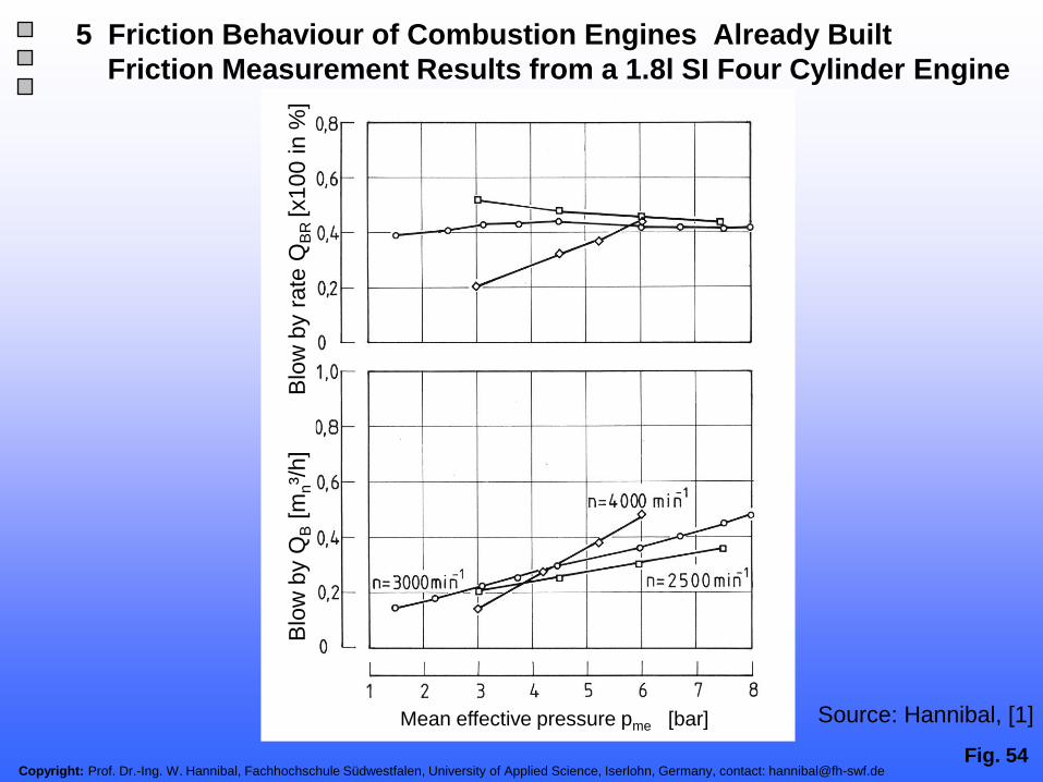
Fig. 54Copyright: Prof. Dr.-Ing. W. Hannibal, Fachhochschule Südwestfalen, University of Applied Science, Iserlohn, Germany, contact: [email protected]
Source: Hannibal, [1]
5 Friction Behaviour of Combustion Engines Already Built
Friction Measurement Results from a 1.8l SI Four Cylinder Engine
Mean effective pressure pme [bar]
Blo
wb
yQ
B[m
n³/
h]
Blo
wb
yra
te Q
BR
[x100 in %
]

Fig. 55Copyright: Prof. Dr.-Ing. W. Hannibal, Fachhochschule Südwestfalen, University of Applied Science, Iserlohn, Germany, contact: [email protected]
Source: Hannibal, [1]
5 Friction Behaviour of Combustion Engines Already Built
Friction Measurement Results from a 1.8l SI Four Cylinder Engine
Engine speed [1/min]
TOil=90 C TWE=80 C
pm
r[b
ar]
Te
mp
era
ture
T [
C]

Fig. 56Copyright: Prof. Dr.-Ing. W. Hannibal, Fachhochschule Südwestfalen, University of Applied Science, Iserlohn, Germany, contact: [email protected]
Source: Hannibal, [1]
5 Friction Behaviour of Combustion Engines Already Built
Friction Measurement Results from a 1.8l SI Four Cylinder Engine
Mean effective pressure pme [bar]
pm
r[b
ar]

Fig. 57Copyright: Prof. Dr.-Ing. W. Hannibal, Fachhochschule Südwestfalen, University of Applied Science, Iserlohn, Germany, contact: [email protected]
Source: Hannibal, [1]
5 Friction Behaviour of Combustion Engines Already Built
Friction Measurement Results from a 1.8l SI Four Cylinder Engine
pm
r[b
ar]
Tem
pe
ratu
re T
[C
]
Coolant Temp. TWE [ C]
Toil=90 C

Fig. 58Copyright: Prof. Dr.-Ing. W. Hannibal, Fachhochschule Südwestfalen, University of Applied Science, Iserlohn, Germany, contact: [email protected]
Source: Hannibal, [1]
5 Friction Behaviour of Combustion Engines Already Built
Friction Measurement Results from a 1.8l SI Four Cylinder Engine
Coolant Temp. TWE [ C]
Toil=90 C
pm
r[b
ar]
Tem
pe
ratu
re T
[C
]
Fig. 59Copyright: Prof. Dr.-Ing. W. Hannibal, Fachhochschule Südwestfalen, University of Applied Science, Iserlohn, Germany, contact: [email protected]
5 Friction Behaviour of Combustion Engines Already Built
Comparison of Measured Mean Friction Pressures
Source: Basshuysen, [2]
Mean f
riction p
ressure
pm
r[b
ar]
Mean effective pressure pme [bar]
Oil/Coolant temperature = 90 C
Fired engine, variation of load
Fired engine, zero load
Motoring mode

Fig. 60Copyright: Prof. Dr.-Ing. W. Hannibal, Fachhochschule Südwestfalen, University of Applied Science, Iserlohn, Germany, contact: [email protected]
5 Friction Behaviour of Combustion Engines Already Built
Influence of the Oil Viscosity on Friction
Source: Basshuysen, [2]

Fig. 61Copyright: Prof. Dr.-Ing. W. Hannibal, Fachhochschule Südwestfalen, University of Applied Science, Iserlohn, Germany, contact: [email protected]
5 Friction Behaviour of Combustion Engines Already Built
Oil Pressure and Oil Volumetric Flow in the Lubrication Circuit
Source: Basshuysen, [2]

Copyright: Prof. Dr.-Ing. W. Hannibal, Fachhochschule Südwestfalen, University of Applied Science, Iserlohn, Germany, contact: [email protected]
Fig. 62
1 Introduction
2 Basic Theoretical Views of Friction and Lubrication
4 Influence of Friction on the Fuel Consumption
3 Methods for Measuring of Friction at Internal Combustion Engines
5 Friction Behaviour of Combustion Engines Already Built
7 Friction of the Engine Block Components
6 Friction of the Valve Train Components
9 Thermo Management
11 Reduction of Friction Through Variable Valve Train
Presentation Outline
10 Reduction of Idle Speed
12 Trends In The Engine Development to Reduce Friction
8 Friction of the Auxiliaries
13 Summary / Outlook

Fig. 63Copyright: Prof. Dr.-Ing. W. Hannibal, Fachhochschule Südwestfalen, University of Applied Science, Iserlohn, Germany, contact: [email protected]
6 Friction of the Valve Train Components
Friction for Several Valve Train Concepts
Mechanical lash adjustment in Comparison
to roller rocker finger
Bucket with hydraulically lash adjustment 1.6 l – 4V (Gen. 2)
Friction range hydraulic buckets
Example for a
bucket with
mechanical lash
adjustmentFriction range roller rocker finger
Engine speed [1/min]
Mean
fri
cti
on
pre
ssu
re
[
bar]
Source: Grebe, [4]

Copyright: Prof. Dr.-Ing. W. Hannibal, Fachhochschule Südwestfalen, University of Applied Science, Iserlohn, Germany, contact: [email protected]. 64
6 Friction of the Valve Train Components
Bucket Valve Train
Hollow
camshaft
Bucket with
mechanical lash
adjustment
Conical
valve spring
Example: GM Powertrain 1,6l – 4V Twinport Source: Grebe, [4]

Copyright: Prof. Dr.-Ing. W. Hannibal, Fachhochschule Südwestfalen, University of Applied Science, Iserlohn, Germany, contact: [email protected]. 65
6 Friction of the Valve Train Components
Torque at the Camshaft
Total camshaft torque
Frictional torque
Torque
Camshaft angle [ CA]
To
rqu
e
[N
m]
0 CA
Torque drives cam
Source: Grebe, [4]

Fig. 66Copyright: Prof. Dr.-Ing. W. Hannibal, Fachhochschule Südwestfalen, University of Applied Science, Iserlohn, Germany, contact: [email protected]
6 Friction of the Valve Train Components
Comparison of Various Valve Train Concepts
Source: Koch, [5]

Fig. 67Copyright: Prof. Dr.-Ing. W. Hannibal, Fachhochschule Südwestfalen, University of Applied Science, Iserlohn, Germany, contact: [email protected]
Camshaft bearings
Valve guide
Bucket guide
EHD contact
Bucket
Leightweight
construction
Roller bearings
Engine speed [1/min]
Me
an fri
ctio
n p
ressu
re
[ba
r]
6 Friction of the Valve Train Components
Breakdown of Friction in the Valve Train
Source: Speckens, [8]

Fig. 68Copyright: Prof. Dr.-Ing. W. Hannibal, Fachhochschule Südwestfalen, University of Applied Science, Iserlohn, Germany, contact: [email protected]
6 Friction of the Valve Train Components
Influence of Coatings
Dri
vin
g t
orq
ue o
f th
e c
yli
nd
er
head
[
Nm
]
Engine speed [1/min]
4Cyl.-4Valve (94) (Bucket)
Optimised (97) (roll)
Ion- emplanted (98) (roll)
Source: Goedeckmeyer, [8]

Copyright: Prof. Dr.-Ing. W. Hannibal, Fachhochschule Südwestfalen, University of Applied Science, Iserlohn, Germany, contact: [email protected]. 69
6 Friction of the Valve Train Components
Roller Contact To The Cam at the Levers
Roller
rocker
finger
Roller
rocker
arm

Copyright: Prof. Dr.-Ing. W. Hannibal, Fachhochschule Südwestfalen, University of Applied Science, Iserlohn, Germany, contact: [email protected]. 70
6 Friction of the Valve Train Components
DLC-Diamant Coating
Hard, diamond like
surface coating,
mostly applied in PVD
(physical vapor deposition).
Direct influence on the
friction surface.
DLC coat- thickness 5 μm.
Approximately 5 %
reduction of friction
Source: Grebe, [4]

Copyright: Prof. Dr.-Ing. W. Hannibal, Fachhochschule Südwestfalen, University of Applied Science, Iserlohn, Germany, contact: [email protected]. 71
6 Friction of the Valve Train Components
…
Built camshaft with
needle bearings.
Needles run directly on
the hardened camshaft.
Valves and valve springs
unaltered for the measuringSource: Grebe, [4]

Copyright: Prof. Dr.-Ing. W. Hannibal, Fachhochschule Südwestfalen, University of Applied Science, Iserlohn, Germany, contact: [email protected]
Fig. 72
1 Introduction
2 Basic Theoretical Views of Friction and Lubrication
4 Influence of Friction on the Fuel Consumption
3 Methods for Measuring of Friction at Internal Combustion Engines
5 Friction Behaviour of Combustion Engines Already Built
7 Friction of the Engine Block Components
6 Friction of the Valve Train Components
9 Thermo Management
11 Reduction of Friction Through Variable Valve Train
Presentation Outline
10 Reduction of Idle Speed
12 Trends In The Engine Development to Reduce Friction
8 Friction of the Auxiliaries
13 Summary / Outlook

Fig. 73Copyright: Prof. Dr.-Ing. W. Hannibal, Fachhochschule Südwestfalen, University of Applied Science, Iserlohn, Germany, contact: [email protected]
7 Friction of the Engine Block and its Components
Friction per Crankshaft Main Bearing Over Main Bearing Diameter
einfügen
Main bearing diameter [mm]
2000 rpm
Oil: SAE 15W50
Oil/Coolant
temperature: 90 C
Regression curve
for SI engines
Regression curve
for diesel engines
Regression curve
for SI R engines
Main bearing diameter³ [cm³]
Main
bearing f
riction m
om
ent [N
m]
Source: Pischinger, [9];
Koch, [5]

Fig. 74Copyright: Prof. Dr.-Ing. W. Hannibal, Fachhochschule Südwestfalen, University of Applied Science, Iserlohn, Germany, contact: [email protected]
7 Friction of the Engine Block and its Components
Friction …
0 180 360 540 720
-100
-200
0
100
Dyn
am
ic f
riction f
orc
e [
N]
Piston ring Package:
Version B: Basic Version
Version C: Optimized pretension
and ring height
Version C
Motored, full load
2000 rpm
Oil/coolant
temperature: 90 C
Dynamic friction force measuring system - PIFFO
Piston friction force
Crankshaft angle [degree]
Version B
Source: Koch, [7]

Fig. 75Copyright: Prof. Dr.-Ing. W. Hannibal, Fachhochschule Südwestfalen, University of Applied Science, Iserlohn, Germany, contact: [email protected]
7 Friction of the Engine Block and its Components
Friction …
Sum of piston ring surfaces pressure
Mean friction p
ressure
[bar]
Piston rings variants: 1, 2, 3, 4
Boundary conditions: Trailed, full load
Temperature 90 C
Source: Koch, [5]

Copyright: Prof. Dr.-Ing. W. Hannibal, Fachhochschule Südwestfalen, University of Applied Science, Iserlohn, Germany, contact: [email protected]. 76
7 Friction of the Engine Block and its Components
Main Influence Parameter of the Crankshaft Component Friction
Number of rings
and tangential
tension
Gliding surface
at the side
Mass of piston
and piston rod
Bearing diameter Source: Grebe, [4]

Fig. 77Copyright: Prof. Dr.-Ing. W. Hannibal, Fachhochschule Südwestfalen, University of Applied Science, Iserlohn, Germany, contact: [email protected]
7 Friction of the Engine Block and its Components
Locations of Friction at the Piston Group
Piston rings
Piston rod
bearing cap
Piston
Piston
pin clip
Large piston
rod eye
Piston rod
bearing
Piston rod
Small piston
rod eye
Piston rod bearing
Piston pin
Piston rod
screw
Source: Grebe, [4]

Fig. 78Copyright: Prof. Dr.-Ing. W. Hannibal, Fachhochschule Südwestfalen, University of Applied Science, Iserlohn, Germany, contact: [email protected]
7 Friction of the Engine Block and its Components
Friction …
Fly Wheel
Crank Shaft
Crank Shaft
Bearing Shells
Starter Gear Ring
Shaft Extension
(Mean Bearing)
Crank Arm
Crank bow
Crank Shaft
Journal
Axial bearing disc
Source: Grebe, [4]

Fig. 79Copyright: Prof. Dr.-Ing. W. Hannibal, Fachhochschule Südwestfalen, University of Applied Science, Iserlohn, Germany, contact: [email protected]
7 Friction of the Engine Block and its Components
Kinematic Situation at the Piston Group
Piston Lateral
Force FN
Combustion
Pressure p
Piston Force FK
Radial Force FR
r: Crank Radius
M: Engine Torque
Connection Rod
Force FP
Tangential Force
FT
Connection Rod
Force FP
Source: Grebe, [4]
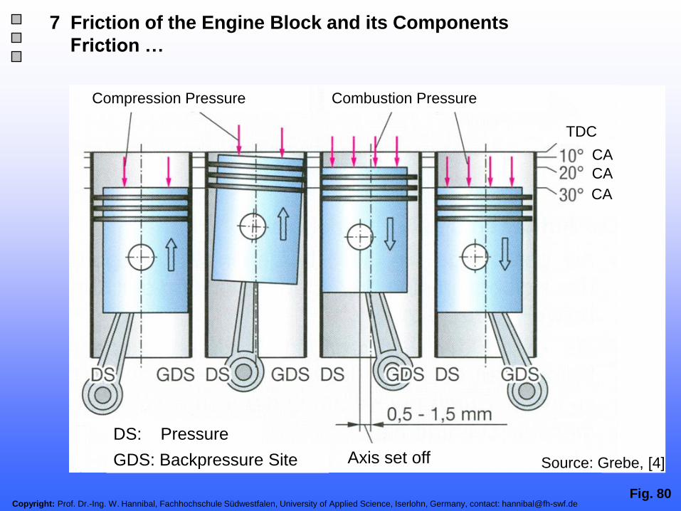
Fig. 80Copyright: Prof. Dr.-Ing. W. Hannibal, Fachhochschule Südwestfalen, University of Applied Science, Iserlohn, Germany, contact: [email protected]
7 Friction of the Engine Block and its Components
Friction …
Compression Pressure Combustion Pressure
DS: Pressure
SiteGDS: Backpressure Site Axis set off
TDC
CA
CA
CA
Source: Grebe, [4]

Fig. 81Copyright: Prof. Dr.-Ing. W. Hannibal, Fachhochschule Südwestfalen, University of Applied Science, Iserlohn, Germany, contact: [email protected]
7 Friction of the Engine Block and its Components
Cylinder Bore Wear; Normal Wear Left, Ahead Time Wear Right
TDC
Reversal point
Region of
high piston
velocity
Source: Grebe, [4]

Fig. 82Copyright: Prof. Dr.-Ing. W. Hannibal, Fachhochschule Südwestfalen, University of Applied Science, Iserlohn, Germany, contact: [email protected]
7 Friction of the Engine Block and its Components
…
Cylinder Wall
Lubrication Gap
Piston
Hydro dynamical
Pressure
Piston
Lateral
Force
Source: Grebe, [4]

Fig. 83Copyright: Prof. Dr.-Ing. W. Hannibal, Fachhochschule Südwestfalen, University of Applied Science, Iserlohn, Germany, contact: [email protected]
7 Friction of the Engine Block and its Components
Influence of Roller Bearing of the Crankshaft
2000 rpm
Main bearing diameter [mm]
Plan bearing
Roller bearing
Radial shaft sealRoller bearing
2000 rpm, 90 C
Friction T
orq
ue
0.2
5 N
m
pm
e
0.1
bar
Oil Temperature [ C]
-72 % -55%-41%
Source: Grebe, [4]

Copyright: Prof. Dr.-Ing. W. Hannibal, Fachhochschule Südwestfalen, University of Applied Science, Iserlohn, Germany, contact: [email protected]
Fig. 84
1 Introduction
2 Basic Theoretical Views of Friction and Lubrication
4 Influence of Friction on the Fuel Consumption
3 Methods for Measuring of Friction at Internal Combustion Engines
5 Friction Behaviour of Combustion Engines Already Built
7 Friction of the Engine Block Components
6 Friction of the Valve Train Components
9 Thermo Management
11 Reduction of Friction Through Variable Valve Train
Presentation Outline
10 Reduction of Idle Speed
12 Trends In The Engine Development to Reduce Friction
8 Friction of the Auxiliaries
13 Summary / Outlook

Fig. 85Copyright: Prof. Dr.-Ing. W. Hannibal, Fachhochschule Südwestfalen, University of Applied Science, Iserlohn, Germany, contact: [email protected]
8 Friction of the Auxiliaries
Friction of the Auxiliaries Necessary for the Engine Operation
Scatter Range
Engine speed [min-1]
Me
an
frictio
n p
ressu
re p
mr[b
ar]
Serial gasoline
engine
Date: 1/2003-1/2009
Number of Engines: 53
Oil: 0W30 – 15W40
Temperature: 90 C
Auxiliaries:
loaded oil pump
loaded water pump
unloaded alternator
(each incl. drive)
Source: FEV
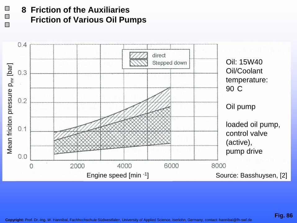
Fig. 86Copyright: Prof. Dr.-Ing. W. Hannibal, Fachhochschule Südwestfalen, University of Applied Science, Iserlohn, Germany, contact: [email protected]
8 Friction of the Auxiliaries
Friction of Various Oil Pumps
Oil: 15W40
Oil/Coolant
temperature:
90 C
Oil pump
loaded oil pump,
control valve
(active),
pump drive
Engine speed [min -1]
Mean f
riciton
pre
ssure
pm
r[b
ar]
Source: Basshuysen, [2]

Fig. 87Copyright: Prof. Dr.-Ing. W. Hannibal, Fachhochschule Südwestfalen, University of Applied Science, Iserlohn, Germany, contact: [email protected]
8 Friction of the Auxiliaries
Oil Pressure and Oil Volumetric Flow in the Lubrication Circuit
Source: Basshuysen, [2]
Copyright: Prof. Dr.-Ing. W. Hannibal, Fachhochschule Südwestfalen, University of Applied Science, Iserlohn, Germany, contact: [email protected]. 88
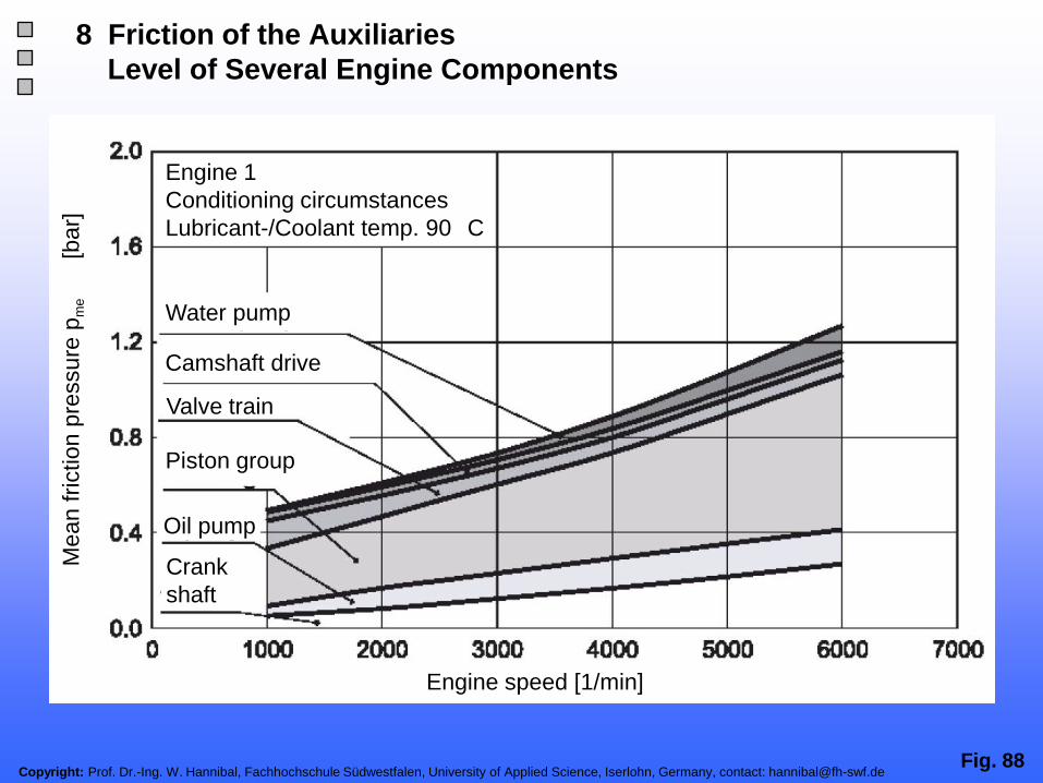
Water pump
Valve train
Piston group
Engine speed [1/min]Engine speed [1/min]
Me
an
frictio
n p
ressu
re p
me
[ba
r]
Oil pump
8 Friction of the Auxiliaries
Level of Several Engine Components
Crank
shaft
Camshaft drive
Engine 1
Conditioning circumstances
Lubricant-/Coolant temp. 90 C

Copyright: Prof. Dr.-Ing. W. Hannibal, Fachhochschule Südwestfalen, University of Applied Science, Iserlohn, Germany, contact: [email protected]
Fig. 89
1 Introduction
2 Basic Theoretical Views of Friction and Lubrication
4 Influence of Friction on the Fuel Consumption
3 Methods for Measuring of Friction at Internal Combustion Engines
5 Friction Behaviour of Combustion Engines Already Built
7 Friction of the Engine Block Components
6 Friction of the Valve Train Components
9 Thermo Management
11 Reduction of Friction Through Variable Valve Train
Presentation Outline
10 Reduction of Idle Speed
12 Trends In The Engine Development to Reduce Friction
8 Friction of the Auxiliaries
13 Summary / Outlook
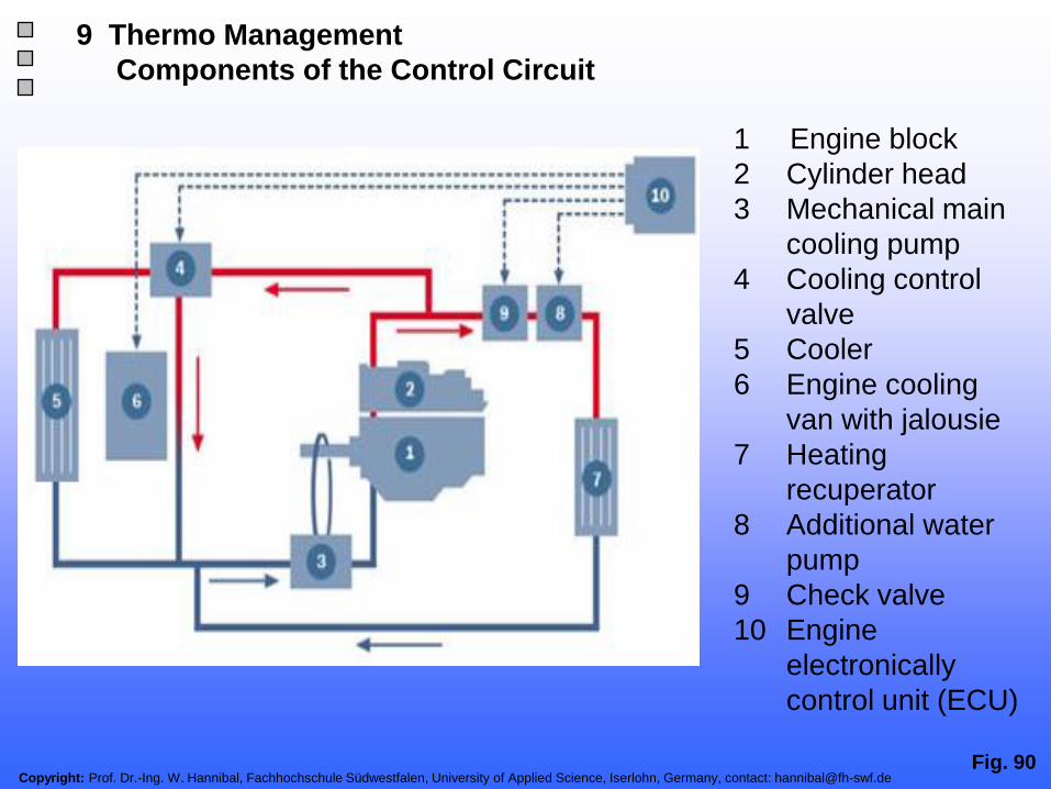
Fig. 90Copyright: Prof. Dr.-Ing. W. Hannibal, Fachhochschule Südwestfalen, University of Applied Science, Iserlohn, Germany, contact: [email protected]
1 Engine block
2 Cylinder head
3 Mechanical main
cooling pump
4 Cooling control
valve
5 Cooler
6 Engine cooling
van with jalousie
7 Heating
recuperator
8 Additional water
pump
9 Check valve
10 Engine
electronically
control unit (ECU)
9 Thermo Management
Components of the Control Circuit
Copyright: Prof. Dr.-Ing. W. Hannibal, Fachhochschule Südwestfalen, University of Applied Science, Iserlohn, Germany, contact: [email protected]. 91
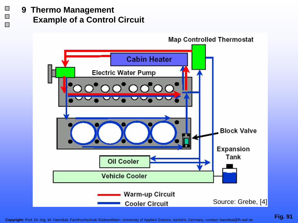
9 Thermo Management
Example of a Control Circuit
Source: Grebe, [4]

Copyright: Prof. Dr.-Ing. W. Hannibal, Fachhochschule Südwestfalen, University of Applied Science, Iserlohn, Germany, contact: [email protected]. 92
9 Thermo Management
Water Flow
Water jacket in
the cylinder headThermostat
electrically
heated
Water manifoldWater jacket in
the cylinder block
Water
pump
Transfers in the
head gasket
Source: Grebe, [4]

Copyright: Prof. Dr.-Ing. W. Hannibal, Fachhochschule Südwestfalen, University of Applied Science, Iserlohn, Germany, contact: [email protected]. 93
9 Thermo Management
Influence on Fuel Consumption in the Test Cycles
Source: Grebe, [4]

Copyright: Prof. Dr.-Ing. W. Hannibal, Fachhochschule Südwestfalen, University of Applied Science, Iserlohn, Germany, contact: [email protected]. 94
9 Thermo Management
Working Principle
Electrically heated thermostat allows engine characteristics
controlled opening of the thermostat
Working Principle
Part load
• High temperature of the cooling fluid (ca. 105-110 C)
• High oil temperature, as the heat transfer is reduced by the
cooling water
• viscosity of the oil decreases → reduced friction
Full load
• maximal cooling for the frigid cylinder head
→ optimized boundary conditions for the engine knocking
→ maximized cylinder charging

Copyright: Prof. Dr.-Ing. W. Hannibal, Fachhochschule Südwestfalen, University of Applied Science, Iserlohn, Germany, contact: [email protected]. 95
9 Thermo Management
Range of 70 % Mechanical Effiency
4 Stroke SI Engine
Average mechanical
efficiency: 70%Source:
MVEG- Test Circle Relevant Range

Copyright: Prof. Dr.-Ing. W. Hannibal, Fachhochschule Südwestfalen, University of Applied Science, Iserlohn, Germany, contact: [email protected]. 96
9 Thermo Management
…
Empirical Formula
effective work on the clutch
indicated work on the piston
Empirical Formula (Goetz AG)
specific fuel consumption [g/kWh]
lowering specific fuel consumption [g/kWh]
mechanical efficiency [-]
mean friction pressure [bar]
lowering mean friction pressure [bar]
With an average mechanical efficiency of 0.7
→ 0.05 bar changing in mean friction pressure (at pmr = 1.5 bar)
→ causes 1 % in the efficiency / fuel consumption

Copyright: Prof. Dr.-Ing. W. Hannibal, Fachhochschule Südwestfalen, University of Applied Science, Iserlohn, Germany, contact: [email protected]
Fig. 97
1 Introduction
2 Basic Theoretical Views of Friction and Lubrication
4 Influence of Friction on the Fuel Consumption
3 Methods for Measuring of Friction at Internal Combustion Engines
5 Friction Behaviour of Combustion Engines Already Built
7 Friction of the Engine Block Components
6 Friction of the Valve Train Components
9 Thermo Management
11 Reduction of Friction Through Variable Valve Train
Presentation Outline
10 Reduction of Idle Speed
12 Trends In The Engine Development to Reduce Friction
8 Friction of the Auxiliaries
13 Summary / Outlook

Copyright: Prof. Dr.-Ing. W. Hannibal, Fachhochschule Südwestfalen, University of Applied Science, Iserlohn, Germany, contact: [email protected]. 98
10 Reduction of Idle Speed
Fuel Consumption Potential
Reducing the idling speed decreases fuel consumption
Rule of thumb:
Reduction of 100 1/min results:
SI engine
0.04 l/h per 1000 cm³ cubic capacityDiesel engine
0.022 l/h per 1000 cm³ cubic capacity
Source: Grebe, [4]

Copyright: Prof. Dr.-Ing. W. Hannibal, Fachhochschule Südwestfalen, University of Applied Science, Iserlohn, Germany, contact: [email protected]. 99
10 Reduction of Idle Speed
Idle Speed Influence
Source: Grebe, [4]
Otto engines
Diesel engines
Idle speed [1/min]
Idle
fuel consum
ption
[l /
h / 1
000 c
m³]

Copyright: Prof. Dr.-Ing. W. Hannibal, Fachhochschule Südwestfalen, University of Applied Science, Iserlohn, Germany, contact: [email protected]. 100
10 Reduction of Idle Speed
Limits
• Combustion System
- Otto engine with exterior fuel- mixture generation allows ca. 500 – 600 1/min
- fuel direct injection allows lower idling speeds due to more stable mixture
generation and more accurate admeasurement
• Oil Pump Dimensioning
- Oil pressure has to be assured ( eventually larger oil pump with higher input
power)
• Vehicle- Auxiliaries Drive System
- alternator limits the idling speed reduction
(further improvements through lower mass inertia, decoupling elements, …)
- control assembly – dynamic
• Driveaway of the Vehicle
- engine speed is necessary for the clutch- in process (clutch modulation)

Copyright: Prof. Dr.-Ing. W. Hannibal, Fachhochschule Südwestfalen, University of Applied Science, Iserlohn, Germany, contact: [email protected]
Fig. 101
1 Introduction
2 Basic Theoretical Views of Friction and Lubrication
4 Influence of Friction on the Fuel Consumption
3 Methods for Measuring of Friction at Internal Combustion Engines
5 Friction Behaviour of Combustion Engines Already Built
7 Friction of the Engine Block Components
6 Friction of the Valve Train Components
9 Thermo Management
11 Reduction of Friction Through Variable Valve Train
Presentation Outline
10 Reduction of Idle Speed
12 Trends In The Engine Development to Reduce Friction
8 Friction of the Auxiliaries
13 Summary / Outlook

Copyright: Prof. Dr.-Ing. W. Hannibal, Fachhochschule Südwestfalen, University of Applied Science, Iserlohn, Germany, contact: [email protected]. 102
11 Reduction of Friction Through Variable Valve Train
Fully Variable Valve Train UniValve of Kolbenschmidt Pierburg AG
guide
forked lever
cam
roller rocker finger
HLAintake valve
spring
'
working curve
eccentric shaft
Source: Hannibal, [10]

Copyright: Prof. Dr.-Ing. W. Hannibal, Fachhochschule Südwestfalen, University of Applied Science, Iserlohn, Germany, contact: [email protected]. 103
11 Reduction of Friction Through Variable Valve Train
Friction of the Variable Valve Train UniValve at Low Speeds
Source: Hannibal, [10]

Fig. 104Copyright: Prof. Dr.-Ing. W. Hannibal, Fachhochschule Südwestfalen, University of Applied Science, Iserlohn, Germany, contact: [email protected]
11 Reduction of Friction Through Variable Valve Train
Friction of the Variable Valve Train UniValve at Low Speeds
Source: Hannibal, [4]

Copyright: Prof. Dr.-Ing. W. Hannibal, Fachhochschule Südwestfalen, University of Applied Science, Iserlohn, Germany, contact: [email protected]
Fig. 105
1 Introduction
2 Basic Theoretical Views of Friction and Lubrication
4 Influence of Friction on the Fuel Consumption
3 Methods for Measuring of Friction at Internal Combustion Engines
5 Friction Behaviour of Combustion Engines Already Built
7 Friction of the Engine Block Components
6 Friction of the Valve Train Components
9 Thermo Management
11 Reduction of Friction Through Variable Valve Train
Presentation Outline
10 Reduction of Idle Speed
12 Trends In The Engine Development to Reduce Friction
8 Friction of the Auxiliaries
13 Summary / Outlook

Copyright: Prof. Dr.-Ing. W. Hannibal, Fachhochschule Südwestfalen, University of Applied Science, Iserlohn, Germany, contact: [email protected]. 106
- Better analysis methods, usage of data basis
- Reduction of contact surfaces
- Usage of roller contacts
- Downsizing
- Optimisation of the lubrication system
- Innovative optimized components like chain tensioners etc.
- Optimisation of the oil quality
- …
12 Trends in the Engine Development to Reduce Friction

Copyright: Prof. Dr.-Ing. W. Hannibal, Fachhochschule Südwestfalen, University of Applied Science, Iserlohn, Germany, contact: [email protected]
Fig. 107
1 Introduction
2 Basic Theoretical Views of Friction and Lubrication
4 Influence of Friction on the Fuel Consumption
3 Methods for Measuring of Friction at Internal Combustion Engines
5 Friction Behaviour of Combustion Engines Already Built
7 Friction of the Engine Block Components
6 Friction of the Valve Train Components
9 Thermo Management
11 Reduction of Friction Through Variable Valve Train
Presentation Outline
10 Reduction of Idle Speed
12 Trends In The Engine Development to Reduce Friction
8 Friction of the Auxiliaries
13 Summary / Outlook

Fig. 108Copyright: Prof. Dr.-Ing. W. Hannibal, Fachhochschule Südwestfalen, University of Applied Science, Iserlohn, Germany, contact: [email protected]
- The reduction of friction is a main development task for achieving a better
fuel consumption
- all engine's components have to be optimized
- The standard valve train will have roller rocker fingers
- The best variable valve train system will also be based on a roller rocker
finger design
- The downsizing concepts will reduce friction thought a consequent light
weight design
- The potential of friction reduction of the engine block components has to be
a main topic in the engine development
- The friction reduction of the auxiliaries like optimised oil pumps is also
significant
- A high political pressure on the CO2 potential reduction will speed up the
engine´s development
13 Summary / Outlook
References in Addition to the Sources in the Slides

Copyright: Prof. Dr.-Ing. W. Hannibal, Fachhochschule Südwestfalen, University of Applied Science, Iserlohn, Germany, contact: [email protected]. 109
13 Summary / Outlook
References in Addition to the Sources in the Slides
[1] Hannibal, W.: Reibungsmessungen an einem schnelllaufenden 4-Takt-Ottomotor. Diplomarbeit, Universität Hannover, 1986
[2] Basshuysen, R.; Schäfer, F.: Internal Combustion. Handbook, SAE InternationalWarrendale, Pa., 2004
[3] Affenzeller, J.; Gläser, H.: Lagerung und Schmierung von Verbrennungsmotoren: Die Verbrennungskraftmaschine.
Band 8, Springer- Verlag, 1996
[4] Grebe, P.: Weiterentwicklung des Ottomotors. Vorlesung an der TU Wien, 2010
[5] Koch, F.; Hermsen, F.; Marckwardt, H.; Haubner, F.: Friction Losses of Combustion Engines – Measurements,
Analysis and Optimization Internal Combustion Engines Experiments and Modeling. Capri, Italy, 15. - 18. 09.1999
[6] Schwaderlapp, M.; Koch, F.; Bollig, C.; Hermsen, F.; Arndt, M: Leichtbau und Reibungsreduzierung – Konstruktive
Potenziale zur Erfüllung von Verbrauchzielen. 21. Internationales Wiener Motorensymposium, Vienna, 04. – 05.05.2000
[7] Koch, F.; Geiger, U.; Hermsen, F.: PIFFO – Piston Friction Force Measurement During Engine Operation. SAE
Paper 960306, 1996
[8] Speckens, F.; Hermsen, F.; Buck, J.: Konstruktive Wege zum reibungsarmen Ventiltrieb. MTZ 59, 1998
[9] Pischinger, R.; Kraßnig, G.; Taucar, G.; Sams, T.: Thermodynamik der Verbrennungskraftmaschine: Die
Verbrennungskraftmaschine. Band 5, Springer- Verlag, 1989
[10] Hannibal, W,; Flierl, F.; Schmitt, S.; Lauer, F.: Schopp, G.; Kleinert, G.: Einsatz teilvariabler und vollvariabler
Ventilsteuerungen für unterschiedliche Ottomotorenkonzepte. Vortrag auf der 3. ATZ-MTZ Tagung , Ladungswechsel im
Verbrennungsmotor, 19. Oktober 2010, Stuttgart
[11] Goedeckmeyer, S.; Windisch, H.: Reibleistungsmessungen an Zylinderköpfen mittels Drehmomentenmessung mit dem
Drehmoment-Meßflansch; Firma HBM, MSR 06/1998
Additional References:
[12] Albers, A.: Konstruktionselemente des Maschinenbaus 2. Vorlesungsskript Universität Karlsruhe, 2008
[13] Bartz, W.: Grundlagen der Tribologie. Esslingen, 2002
[14] Kochanovsky, H.: Der Totpunktfehler bei der Bestimmung des indizierten Mitteldruckes von Verbrennungskraftmotoren.
MTZ 37 (1976) 1/2
[15] Ullrich, W.: Einfluss des Totpunktfehlers auf die Bestimmung des indizierten Mitteldrucks. Ingolstadt, 1983
[16] Szengel, R.: Einfluss konstruktiver Parameter auf die Reibungsverluste der Kolbengruppe eines Hubkolbentriebwerkes.
Dissertation, Universität Hannover, 1985
[17] Paland, E.: Hydrodynamische Gleitlager. Vorlesungsskript Universität Hannover, 1984

Copyright: Prof. Dr.-Ing. W. Hannibal, Fachhochschule Südwestfalen, University of Applied Science, Iserlohn, Germany, contact: [email protected]. 110
13 Summary / Outlook
General References in Addition to the Sources in the Slides
[18] Huber, K.: Reibungsarmer Verbrennungsmotor. Vortrag KKK, 1996
[19] Affenzeller, J. : Lagerung und Schmierung von Verbrennungsmotoren - Die Verbrennungskraftmaschine. Springer, 1996
[20] Koch, F.; Haubner, F.; Schwaderlapp, M.: Thermomanagement beim DI Ottomotor – Wege zur Verkürzung des
Warmlaufs. 22. Internationales Wiener Motorensymposium, Vienna, 26.04 - 27.04.2000
[21] Koch, F.; Geiger U.: Reibungsanalyse der Kolbengruppe im gefeuerten Motorbetrieb. GfT Tribologie- Fachtagung,
Göttingen, 5/6 November 1996
[22] Haas, A.: Aufteilung der Triebwerksverluste am schnellaufenden Verbrennungsmotor mittels eines neuen
Messverfahrens. RWTH Aachen, Dissertation, 1987
[23] Koch, F.; Fahl, E.; Haas, A.: A New Technique for Measuring the Bore Distortion During Engine Operation. 21st
International CIMAC Congress, Interlaken, 1995
[24] Haas, A.; Esch, T.; Fahl, E.;Kreuter P.; Pischinger, F.: Optimized Design of the Lubrication System of Modern
Combustion Engines. SAE Paper 912407, 1991
[25] Haas, A.; Fahl, E.; Esch, T.: Ölpumpen für eine Verlustarme Motorschmierung. Tagung ‘‘Nebenaggregate im
Fahrzeug‘‘, Essen, 1992
[26] Haas, A.; Kreuter, P.; Maassen, F.: Measurement and Analysis of the Requirement of the Dynamical Bearings in High
Speed Engines. SIA Nr. 91191, Strasbourg, 1991
[27] Esch, T.: Luft im Schmieröl – Auswirkungen auf die Schmierstoffeigenschaften und das Betriebsverhalten von
Verbrennungsmotoren. Lehrstuhl für Angewandte Thermodynamik, RWTH Aachen, 1992
[28] Haas, A.; Stecklina, R.; Fahl, E.: Fuel Economy Improvement by Low Friction Engine Design. Second International
Seminar ‘‘Worldwide Engine Emission Standards and How to Meet Them‘‘, London, 1993
[29] Haubner, F.; Klopstein, S.; Koch, F.: Cabin Heating – A Challenge for the TDI Cooling System. SIA Congress, Lyon,
10.- 11.05.2000
[30] Bolenz, K.: Entwicklung und Beeinflussung des Energieverbrauchs von Nebenaggregaten. 3. Aachener Kolloqium
Fahrzeug- und Motorentechnik, 1991
[31] Gorille, I.: Leistungsbedarf und Antrieb von Nebenaggregaten. 2. Aachener Kolloqium Fahrzeug- und Motorentechnik,
1991
[32] Henneberger, G.: Elektrische Motorausrüstung. Vieweg Verlag, Wiesbaden, 1990
[33] Fahl, E.; Haas, A.; Esch, T.: Dynamisch belastete Gleitlager im Verbrennungsmotor . Tagung, Technische Akademie
Esslingen, 1990

Copyright: Prof. Dr.-Ing. W. Hannibal, Fachhochschule Südwestfalen, University of Applied Science, Iserlohn, Germany, contact: [email protected]
Thank you very
much for your
attention
Fig. 111
Friction in Internal Combustion Engines
Mean effective pressure pme [bar]
Mean f
riction p
ressure
pm
r[b
ar]