frequency response - docceptor.net
TRANSCRIPT

Capacitor
2
• Definition of a capacitor
Q = CV I = C(dV/dt)
To change voltage, current must flow into/from the capacitor.
It is impossible to abruptly change voltage across a capacitor
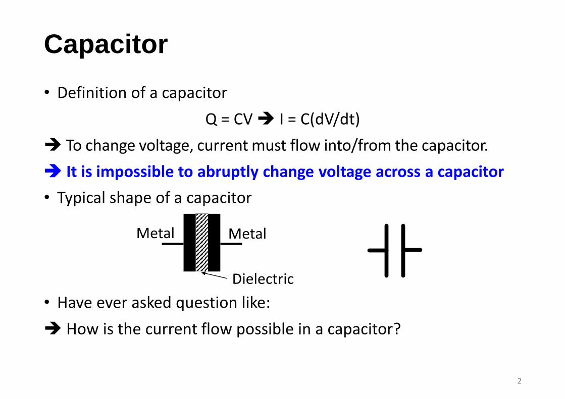
• Typical shape of a capacitor
• Have ever asked question like:
How is the current flow possible in a capacitor?
Metal Metal
Dielectric

Current is Nothing but Charge Flow
• Charge cannot flow through the dielectric, but the charge flow seen at the outside is exactly as the charge flows into it.
• This current is formed only during the voltage is changing.
No change in voltage means no current flow in a capacitor
Less change cap can be let open while being meaningful when signal changes frequently.
3

Forming Differential Equation
• Can you derive the differential eq. relating vout(t) to vin(t)?
4
+-vin(t)
R
C
vout(t) ( ) ( ) ( )in out outv t v t dv tC
R dt
( )( ) ( )out
out in
dv tRC v t v t
dt

Laplace Transform for Solving Differential Equation
• Unilateral Laplace transform is defined as
where s is complex number. They comprise a pair as
• When f(t) is differentiated in the time domain,
5

Revisit RC Circuit
• If vout(0) = 0,
• Note that capacitor can be dealt with in the same manner with a resistor whose value is 1/sC in the s domain.
6
+-vin(t)
R
C
vout(t)
( )( ) ( )out
out in
dv tRC v t v t
dt
( ) ( ) ( )out out inRsCV s V s V s
( ) ( ) ( )in out outv t v t dv tC
R dt
( ) ( )( )in out
out
V s V ssCV s
R
( )
1outV s
sC

AC Circuit; Sinusoidal Signal Input
• Sinusoidal input for linear circuit at the steady state. All the I-V signal in the circuit have the frequency of ω (rad/s).
• That is, any voltage and current can be represented as
• Suppose the voltage across a cap is vC(t) = V0cos(ωt) then,
• We can see the higher the frequency is, the larger the current flow in a capacitor is.
7
0( ) cos( )Vv t V t 0( ) cos( )Ii t I t
( )( ) C
C
dv ti t C
dt 0 0sin( ) cos( 90 )CV t CV t
+ 90° in phase ×ωC in magnitude

Relating to Laplace Transform
• Recall that
• On the other hand, for an AC circuit with sinusoidal input whose freq is ω, vC(t) = V0cos(ωt) then
• That means s = jω and we can see the frequency response from it. Espeically, 1/sC = 1/jωC is called impedance of a cap.
8
( )( ) C
C
dv ti t C
dt ( ) ( )C CI s sCV s
0( ) cos( 90 )Ci t CV t
90
( ) ( )s
C CI s Ce V s

What if Frequency Changes? (1)
• At low freq, C is nearly open Why?
• As freq ↑, decreased impedance of C results in a large vout(t). At high frequency. we cannot ignore the cap
• In general, we can analyze the circuit using the impedance concept 1/sC = 1/jωC for frequency response.
9
+-vin(t)
R
C
vout(t)
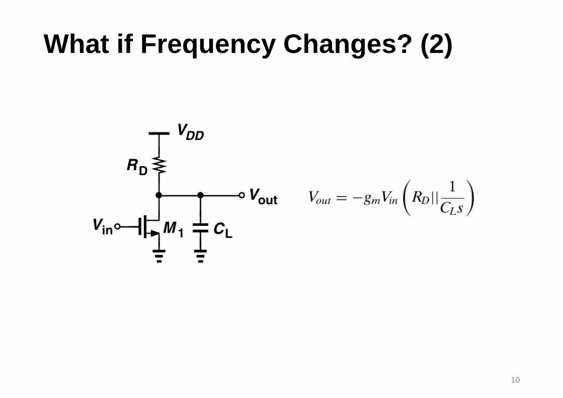
What if Frequency Changes? (2)
10

Transfer Function & Frequency Response
• The transfer function H(s) is output to input ratio in the s domain (Laplace transformed) when the initial conditions are zero.
• ωzj and ωpj represent the zeros and poles of H(s), respectively.
• When input is x(t) = A cosωt, the output can be expressed as
• Frequency response can be represented with the magnitude and phase of H(s) when s=jω, that is H(jω)
11
( )( )
( )
output sH s
input s

12

Bode Plot
• The Bode plot is a chart of H(jω) in decibels and phase in degrees versus the logarithm of frequency.
• The logarithm of the magnitude, the gain in dB:
Unit : decibel (dB)
Frequency (rad/s, logarithm scale)
Mag
nit
ud
e (d
B)
Ph
ase
(deg
ree)
13

Asymptotic Bode Plot
14

Bode’s Rules
|H(jω)| can be approximated with the following rules:
• As ω passes each pole frequency, the slope of |H( jω)| decreases by 20 dB/dec. (A slope of 20 dB/dec simply means a tenfold change in H for a tenfold increase in frequency);
• • As ω passes each zero frequency, the slope of |H( jω)| increases by 20 dB/dec.
15

Association of Poles with Nodes
• The poles of H(s) can tell “speed bottleneck.” of a circuit
You should identify the poles intuitively.
• In the previous CS example, how was ωp is given?
• Generally, if node j in the signal path exhibits a small signal resistance of Rj to ground and a capacitance of Cj to ground,
16
ωp = 1/RjCj

17

18