frequency meter - radionerdsradionerds.com/images/3/38/tm-11-2623.pdf · when frequency meter...
TRANSCRIPT

-WAR DEPA RTMENT TECHNICA L MANUAL
FREQUENCY METER BC-906-E
Gs (.1
WAR DEPARTMENT '26 JULY 1944

WAR DEPARTMENT TECHNICAL MANUAL
T MIL " 2 6 2 3
FREQUENCY METER BC-906-E
• WAR DEPARTMENT 26 JUL ,Y 1944
RESTRICTED. DISSEMIN.ATIO}{ OF RESTRICTED MATTER. The information contained in restricted documents and the essential characteristics of restricted materiel may be given to any person known to be in the service of the United States and to persons of undoubted loyalty and discretion who are cooperating in Government work, but will not be communicated to the public or to the press except by author' i7;ed military public relations agencies. (See also par. 28, AR 380,5, 15 Mar 1944.) .
I
WAR DEPARTMENT, WASHINGTON 25, D. C., 26 July 1944.
TM 11,2623, Frequency Meter BC,906,E, is published for the information and guidance of all concerned.
[A. G. 300.7 (19 June 44).J
BY ORDER OF THE SECRETARY OF WAR:
OFFICIAL: J. A. ULlO,
Major General, 'The Adju.tant General.
DISTRIBUTION: IBn &' HI (5); IC 11 (5)
(For explanation of symbols see FM 2 1 6. )
II
G. C. MARSHALL, Chief of Staff.

TABLE OF CONTENTS
Paragraph Page SECTION 1. Description.
General. .. .. .. . . . . . . . . .. . . . . . . . . . . . 1 Frequency Meter BC-906-E ..... . . . . .. 2 i
II. Operating instructions.
Initial procedure . .. .... . ............ 3 3 Preparation for use as frequency meter 4 3 Determining unknown frequencies . . . . . . 5 3 Tuning to a desired frequency ........ 6 5 Use as a microammeter .............. 7 5 Completion of tests ...... .. ......... 8 5
III. Functioning of parts.
Theory............................ 9 7
IV. Maintenance.
Checking the frequency meter ........ 10 9 Replacing batteries in frequency meter.. 11 11 Servicing the frequency meter ......... 12 11 Frequency meter alignment . . . . . . . . . . . . 13 11
V. Supplementary data.
Maintenance parts list ................ 14 15
III
LIST OF ILLUSTRATIONS
me 1 Frequency Meter BC-906-E ................... . . ...... ... VI 2 Frequency Meter BC-906-E, with antenna in place .. ..... . . 4
3 Frequency Meter BC-906-E, top view of chassis ........... 6
4 Frequency Meter BC-906-E, schematic diagram ............ 10
5 Frequency Meter BC-906-E, voltage and resistance diagram .. 12

DESTRUCTION NOTICE
WHY - To prevent the enemy from using or salvaging this equipment for his benefit.
WHEN - When ordered by your commander.
HOW -1. Smash - Use sledges, axes, handaxes, pickaxes, hammers, crowbars, heavy tools.
2. Cut - Use axes, handaxes, machetes.
3. Burn - Use gasoline, kerosene, oil, flame throwers, incend-iary grenades.
4. Explosives - Use firearms, grenades, TNT.
5. Disposal - Bury in slit trenches, fox holes, other holes. Throw in streams. Scatter.
USE ANYTHING IMMEDIATELY AVAILABLE FOR DESTRUCTION OF THIS EQUIPMENT.
WHAT - 1. Smash - Meter, controls, panel, case, tubes.
2. Cut - Cables and all wiring.
3. Burn - All technical manuals, instruction books, calibration charts, schematics.
4. Bury or scatter - Any or all of the above pieces after destroy-ing their usefulness.
DESTROY EVERYTHI'NG
v
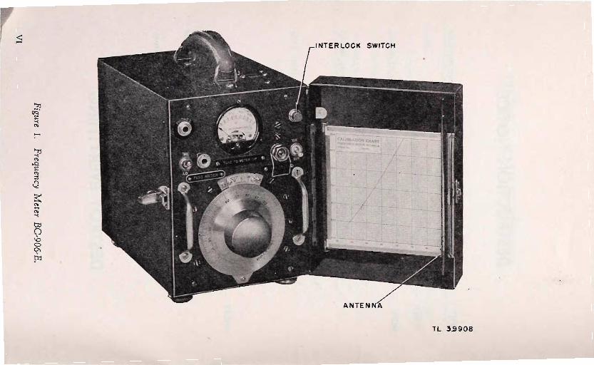
Figure 1. Frequency M
(!ter BC-906-E.
VI
(I) o C1>
'" .., ..J t-

RESTRICTED
SECTION I DESCRIPTION
1. GENERAL. Frequency is measured by counting the number of cycles or oscill ations per second. Since this cannot be done directly, except at very Jow frequencies, in practice the measurement is made by:
o. Noting the response of a selective resonant device, such as a tuned circuit (absorption frequency !!!eter, Wier! bridge, etc or !!!echaf!ica! resonator (tuning fork, vibrating reed, etc.) prevlOusly cahbrated 111 terms of frequency.
b. Comparing the unknown with a known frequency from a separate source, either matching it directly by varying a calibrated source (heterodyne frequency meter) or measuring the difference between it and a fixed source (frequency standard), the frequency of which is known with high precision by interpolation.
2. FREQUENCY METER BC-906-E. a. Frequency Meter BC,906,E (fig. 1) is an absorption'type frequency
meter powered by batteries. The instrument is used to determine the fre' quency of 1"'f signals and to calibrate radio equipment. The meter mounted on the front panel of Frequency Meter BC,906,E may be used independently as a microammeter. When used as a frequency meter, the set is accurate within ±O.5 megacycles. The frequency range of Frequency Meter BC'906,E is from 150 to 234 megacycles.
b. It weighs 17.8 pounds. The frequency meter is housed in a black wrinkle,finish metal cabinet. Mounted on the front panel is a friction ver' nier,drive dial equipped with a vernier attachment which enables a scale reading to be taken in tenths of a division. Also mounted on the front panel are a microammeter (used to indicate resonance with an r,f signal or as a test meter), a test'meter jack (used to connect the microammeter for reading external current values), a phone jack (with a headset, can be used in place of the microammeter for indicating resonance with an r,f signal): a socket for a coaxial connector (wired in parallel with the antenna socket) , an
1

ON-OFF switch, a HI-LO switch (used to change the sensitivity of the frequency meter), and an interlock power switch. When the door of the cabinet is closed the interlock switch shuts off the power. A calibration chart is mounted in the door of the frequency meter.
c. The antenna consists of three sections and is 20 inches in length ex-tended, 8% inches in length collapsed. The antenna is held in place by a socket available through the top of the frequency meter case. When not in use the antenna is stored in the door of the frequency meter.
d. Battery BA-53-A, 45 volts, furnishes current for the plate circuit, and Battery BA-35 (or subsequent production), 1.5 volts, furnishes current for the filament circuit. The current drains are approximately 0.05 ampere at 1.5 volts, and 2 milliamperes at 45 volts.
e. A table of components is given below.
I Name of component I Approximate dimensions
(inches)
1 Antenna (extension type) 20 x 0.218 1 Battery BA35, 1.5 volts 3% x 2% x 2% 1 Battery BA 53 -A, 45 volts 4% x 3 x 1% 1 Chart (calibration) x 5% 1 Tube VT-I72 (comm. IS5) x %
2.

SECTION II OPERATING INSTRUCTIONS
3. INITIAL PROCEDURE. o. Take out the four screws in the front panel and remove the frequency
meter from its case.
b. Check that the batteries are connected as described in paragraph II.
c. Check that the tube is mounted firmly in its socket.
d. Replace the frequency meter in its case, and replace the screws.
4. PREPARATION FOR USE AS FREQUENCY METER. o. Remove the antenna from the clips just inside the door of the frequency
meter; insert it through the hole in the top of the case and pull out the sec-tions to full length. Be sure the base is plugged into the antenna socket.
b. Turn ON-OFF switch ON.
c. Set HI-LO switch to LO position. The pointer should move to approxir mately the 450 mark on the meter scale.
d. If it does not move, remove the meter from the case (par. 3a) and turn rheostat (R-4) on the right-hand side of the subpanel until the 450 mark is reached.
e. Set the HI-LO switch to the HI position. The meter pointer should be at 250; if not, readjust the rheostat for best compromise between 450 on LO and 250 on HI.
5. DETERMINING UNKNOWN FREQUENCIES. When Frequency Meter BC-906-E is used with an input signal, collapse the antenna for high frequen-cies and extend the antenna for low frequencies. To use Frequency Meter BC-906-E for determining an unknown frequency, proceed as follows:
o. Place the frequency meter beside the equipment being checked for frequency. Set the HI-LO switch to the desired position and turn on
3

TL 39909
Figure 2. Frequency Meter BC-906-E. with antenna in place.
4

ON-OFF switch ON. (Set the HI-LO switch to the HI position for use with a low-power input signal.)
b. Rotate the calibrated dial until the meter needle reaches the point of greatest dip.
c. If a headset is used, tune to maximum volume .
. d. Consult the calibration chart to obtain frequency of the input signal.
e. Turn the ON-OFF switch OFF.
6. TUNING TO A DESIRED FREQUENCY. o. Place the frequency meter beside the equipment being aligned.
b. Set the HI-LO switch to the desired position and turn the ON·OFF switch ON. (Set the HI·LO switch to the HI position for use with a low· power input signal.)
c. Set the frequency meter to the desired frequency.
d. Adjust the equipment being aligned for maximum dip on the micro· ammeter of the frequency meter.
e. If a headset is used, adjust for maximum volume.
f. Turn off the frequency meter.
7 USE AS A MICROAMMETER. To use Frequen<;y Meter BC·906·E as a '. mmeter turn the ON·OFF switch to OFF. Connect from the source mlcroa . ' . of current to the TEST METER Jack of the frequency meter. .
CAUTION: The will be damaged if the current exceeds. 500 microamperes.
8 .. COMPLETION OF TESTS. Upon completion of tests be sure that all switches are in their OFF or neutral positions and the antenna rod is placed back in its holding clips (fig. 1) .
5

INTERLOCK SWITCH 5-3
BATTERY BOX
VT - 172
METER M-I TeST JACK
PHONE JACK
RESONATOR
TL 39910
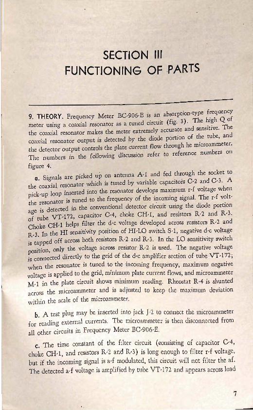
Figure 3. Frequency Meter BC,906,E, top view of chassis.
6
SECTION III FUNCTIONING OF ·PARTS
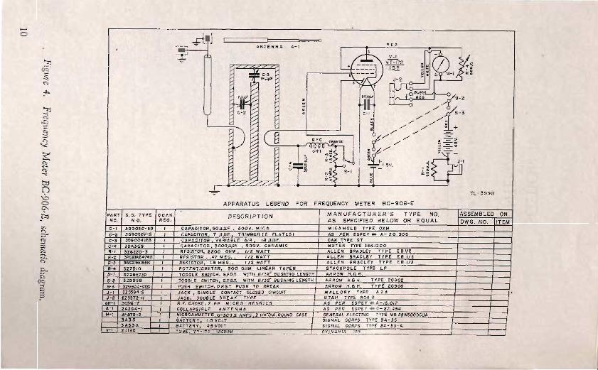
9. THEORY. Frequency Meter BC,906,E is an absorption-type frequency meter using a coaxial resonator as a tuned circuit (fig. 3). The high Q of the coaxial resonator makes the meter extremely accurate and sensitive. The coaxial resonator output is detected by the diode portion of the tube, and the output controls the plate current flow through he microammeter. The numbers in the following discussion refer to reference numbers on figure ,4.
o. Signals are picked up on antenna A, I and fed through the socket to the coaxial resonator which is tuned by variable capacitors C,2 and C,3. A pick'up loop inserted into the resonator develops maximum r,f voltage when the resonator is tuned to the frequency of the incoming signal. The r-f volt, age is detected in the conventional detector circuit using the diode portion of tube VT,172, capacitor C,4, choke CR-I, and resistors R,2 and R,3. Choke CH,1 helps filter the d,c voltage developed across resistors R,2 and R,3. In the HI sensitivity position of HI,LO switch S, I, negative d,c voltage is tapped off acroSS both resistors R,2 and R,3. In the LO sensitivity switch position, only the voltage across resistor R,2 is used. The negative voltage is connected directly to the grid of the d,c amplifier section of tube VT,I72; when the resonator is tuned to the incoming frequency, maximum negative voltage is applied to the grid, minimum plate current flows, and microammeter M,1 in the plate circuit shows minimum reading. Rheostat R,4 is shunted acrosS the micro ammeter and is adjusted to keep the maximum deviation within the scale of the micro ammeter.
b. A test plug may be inserted into jack }2 to connect the microammeter for reading external currents. The microammeter is then disconnected from a11 other circuits in Frequency Meter BC,906,E.
c. The time constant of the filter circuit (eonsisting of capacitor C,4, choke CH, l , and resistors R,2 and R,3) is long enough to filter d voltage, but if the incoming signal is a,f modulated, this circuit will not filter the af. The detected a,f voltage is amplified by tube VT,172 and appears acrosS load
7

resistor R-1 when jack ]- 1 is open-circuited. The a-f voltage swing is greatest when the r-f circuits are tuned to the incoming frequency, even though the average (d-c) plate current is at a minimum. Therefore, when a headset is plugged into jack ]-1, the loudest tonc from a pulse-modulated, or other a-f modulated signal indicates that the frequency meter is tuned to the incoming frequency.
8

,. l
SECTION IV MAINTENANCE
Unsatisfactory performance of this equipment will be reported immediately on W.D., A.G.O. form No. 468. If form is not available, see TM 38-250.
10. CHECKING THE FREQUENCY METER. When failure is encountered, check the items in the trouble location and remedy chart shown below before starting a detailed check.
FREQUENCY METER BC-906-E TROUBLE CHART
'Trouble Possible causes Remedy
Meter deflection Weak batteries. Check voltage, replace incorrect BA,35 when voltage
is less than .9 volts, BA53,A when less than 34 volts.
Faulty tube. Check circuit, replace. Wrong setting Adjust rheostat R'4.
Rheostat R '4.
Poor meter Faulty connections. Check circuit, repair. response Defective tube. Check voltage, replace
defective tube. Faulty parts. Replace. Weak batteries. Check voltage, replace
BA,35 when voltage is less than .9 volts, BA53,A when less than 34 volts.
Frequency cover' Loose connections. Check circuit, repair. age incorrect Faulty parts. Replace.
Misalignment. *Align frequency meter.
*Use only a signal generator which IS accurate within ±O.5 megacycles.
9
-0
O<:!
'"
'" ...Q
'" C"')
'" <"i-
'" b::I
If __ -, J I I : ANTENNA .E.
.-, p: V- I - < 4 ---- VT- 172 3: -. <
liE. / , --- ;::., + M- I >a::. lOW' ' \ J - 2
V: ''AT §
1 o 0- ' / [ - 3 . / / // / / : +
) ;:: ( -g:// // = . 0 % .- -% 'T' ': f-o " §: .... N; S- I "" •
0 -0 TL-39911
0
'" APPARATUS LEGEND FOR FREQUENCY METER BC - 906-E
PART S . C. TYPE OUAN. DESCRIPTION M A NUFACTURER'S TYP E NO. ASSEMBLED ON HO. H O. REQ . AS SPECIFIED BELOW OR EQUA L DWG . NO. ITEM
en C"') ;3"'
c-, , CAPACITOR 50,uUF. SOOV . MICA MICA MOLD TY P E OXM 0-2 3D900av-8 , CAPACITOR 7 UJlF. TRIMMER (2 PLATES) AS PE R ESP Ey .... A - 20 . 006
'" ;l C-' 309004\1\3 , t;APAClrOR VARIABLE AIR '8 F. OAK TYPE Sf C-' 3DA3-e9 , CAPACITOR 3000JJJ.1F. SOOV. CERAMIC MUT E R TYPE 38KI200
I'> <"i-;::;.
R-' 3Z6220-3 , RESISTOR 2200 OHM 1/2 WATT AL LE N BRADLEY TYPE E 8112 R-2 3RC2JAE474K , RESISTOR .47 MEG. 1/2 WATT ALLEN BRADLEY TYPE E B 1/2 R-' 3RC2lBE155K , RESISTOR 1. 5 MEG. 1/2 WATT ALL EN BRADLEY TyP E E B 1/2
Po. \ R-4 3Z7510 , POTENTIOMETER. 500 OHM LINEAR TAPER STACKPOLE TYPE LP
i::' O<:!
$-1 3 Z9857.10 , TOGGLE SWITCH. SPOOr. WITH 11/32- BUSHING LENGTH ARROW H. B H. S-2 3 Z9858 , TOGGLE SWITCH D.P.S.T. WITH 11/32"' BUSHING LEHGTH ARROW H.SH . TYPE 20902
I'> &-, 3Z9824·269 , PUSH SWITCH,D.P.S.T. PUSH TO BREAK ARROW H. Ell H. TYPE 20908 J - ' 2Z5594-2 , JACK SINGLE CONTACT CLOSED CIRCUIT MA L LORY TYPE A2A J - 2 2Z5572·11 , JACK. DOUBLE BRE AK TYPE UTAH TYPE .5048
CH·I 3C3IB - 7 , R. F. CHOKE. 2.66 MICRO· HENRIES AS PER ESPEY .... A-I6.017 A-' 2A294-1 , COLLAPSIBLE ANTENNA AS PER ESPEY ..... C 27. 4.54 ,,-, 3 F87.5-2 , MICROAMMETER 0 .500.u AMPS. 2 114"DIA. ROUND CASE GENERAL TYPE MR 2.5W.5000CUA
3A3.5 , ATTER Y 1.5 VOLT SIGNAL CORPS TYPE SA- 3.5 3 A 53A , BATT ERY. 45 VOLT SIGNAL CORPS TYPE SA -53- A v-, 2JIS.5 , TUBE- VT- 172 • VACUUM SYLVANIA '55
11. REPLACING BATTERIES IN FREQUENCY METER. To replace bat-teries in Frequency Meter BC-906-E, proceed as follows:
a. Remove the frequency meter from its case and remove the cover to the battery box (the black box located on top of the chassis).
b. Remove the old batteries and disconnect the leads.
c. Connect the green lead to the plus (+) terminal of the new Battery BA-3 5 and connect the blue lead to the minus (-) terminal of the same battelY·
d. Connect the red lead to the +45-volt terminal of the new Battery BA 3 5 -A, and connect the yellow lead to the minus (-) terminal of the same battery.
e. Place Battery BA-35 in the battery box with the terminals toward the front of the instrument and slide Battery BA-3 5-A edgewise into the battery box.
f. Replace the top of the battery box and reinstall the frequency meter in its case.
12. SERVICING THE FREQUENCY METER. Servicing Frequency Meter BC,906-E usually is only a matter of checking the batteries. After installing batteries, check the meter deflection as instructed in paragraph 4. If the voltage is low after installing new batteries, make voltage and resistance checks, referring to figure 5. The readings on this figure provide a complete circuit check of the frequency meter. All voltage checks are made to ground with a 1000-ohm-per-volt voltmeter. The resistance readings are made to ground with the power switch OFF and the batteries connected. When re-placing tube VT-172, be careful not to break the glass seal around the connector pins.
13. FREQUENCY METER ALIGNMENT.
a. Equipment Used. The items required for alignment of the frequency meter consist of the following: (1) One standard screwdriver. (2) One insulated screwdriver. (3) A signal generator with an output accurate to within +0.5 megacycles.
b. Deflection Alignment. Remove Frequency Meter BC-906-E from its case and set the HI-LO switch at LO. Adjust rheostat R-4, mounted on the right-hand side of the subpanel until the meter reads 400 to 450.
c. Frequency Alignment. Frequency alignment should be carried out as follows:
11

BOTTOM VIE W OF SOCKE T
.CAUTION! FRONT
RESISTANCE ' READINGS TAKEN WITH POWER SWITCH OFF.
AL.L. VOL.TAGE AND RESISTANCE MEASURE -MENTs MADE WITH RESPECT · TO CHASSIS GROUND ON 20,000 OHM / VOL.T METER.
VOLTAGE READINGS TAKEN WITH SWITCH ON L.OW AND METER ADJUS TED TO 500 MICRO-AMPERES DEFLECTION BY MEANS OF 500 OHM POTENTIOMETER.
*OENOTES CHANGE IN READINGS WHEN SWITCH IS CHANGED TO HI.
o V.D.C. , 0.0. __ _
1.4 V.D.C.,20 1l.
-0.03vn.C.,500MA *(- 0 .35 V.D.C.,2MEG.m VT-172 (I S 5)
-0 .38 V.D.C.,1.9MEGn.
44 V. D.C: , oo.n.
''__ __ 44V.D.C.,oo.n.
REAR TL. 39912
Figure 5. Frequency Meter BC-906-E. voltage and resistance diagram.
(1) Remove Frequency Meter BC-906-E from its case. (2) Install the antenna and place the frequency meter beside the signal generator. (3) Turn ON the signal generator and set it to 190 megacycles with the output at maximum. ( 4) Set the calibrated dial of the frequency meter to the calibration point for 190 megacycles and turn the ON-OFF switch to ON. (5) With the HI-LO switch set to LO, adjust capacitor C-2 for maximum dip on the microammeter of the frequency meter. (6) Turn the ON-OFF switch OFF, remove the antenna, and replace the frequency meter in its case.
13

'(i"
SECTION V SUPPLEMENTARY DATA
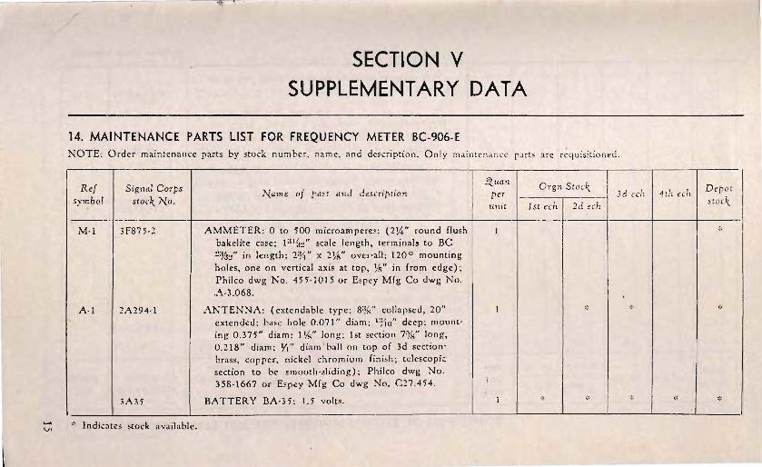
14. MAINTENANCE PARTS LIST FOR FREQUENCY METER BC-906-E NOTE: Order main ten an ce parts by stock num ber, nam e, and O nly maintena nc e rarts are
Ref S ignal Corps "), 1 f d ' . I Depot b I
l. " arne 0 r aTt and eSeTl pt lon per 3d eeh 4th ech syrn 0 stoe,,- No. . 1 h stoel{ st ee
M -l 3F875-2 AMMETER: 0 to 500 microamperes; (21,4" round flush ., bakelite case; 1 :II!!:!" scale length, terminals to BC 2%/' in length ; 2:Y. " x over-all; 120 ° mounting holes, one on vertical axis at top, lAI" in from edge); Philco dwg N o. 455-1015 or Espey M fg Co dwg No. A-3 .068.
Al I 2A294· ! ANTENNA: (extendable type; ccllapsed, 20" '" * extended; hole 0 .07!" diam; deep : mount-ing 0 .375" diam ; 111..(' lon g ; 1st section 7%" long. 0.218" diam; YI" diam ' ball on top of 3d section' brass. copper. nickel chro mium finish; telescopi.: section to be smooth -slidin g ) ; Philco dwg No. 358-1667 or Espey Mfg Co dwg No. C 27.454 .
3A 35 BATTERY BA-35 : 1.5 volts. I ., I * * * ;' "
v. ,:. Indicates stock avail able.

-0\ 14. MAINTENANCE PARTS LIST FOR FREQUENCY METER BC-906-E (clOnt'd).
Ref symbol
COl
C-4
C-2
Signal Corps stoc/{ /Xo .
3AnA
IF4PI-5.14.6
3D9050-59
3DA3-29
3D9008V-8
* Indicates stock available .
/Xame of part and description
BATTERY BA-53-A: 45 volts.
CABLE ·ASSEMBL Y: coaxial; consists of cable 14%" long made of 7 strand copper wire conductor, dielectric core; tinned copper braid outside covering; Y-l" from both ends of wire is hot tin dipped; cable support No. 20 V.S.S. Steel, tinned approx 2" long, one end is curved to a diam, ]%6" from other end is 2%2" outer diam and 0.453" inner diam; clip, steel, cadmium-plated, 0.032" thick, diam of stud hole No. 6-8; Philco dwg No. 358-2146.
CAPACIT:)R: 50 mmf -+-10%; 500v doc working; (XM262 molded bakelite case; approx dim VIs" x lYlt;" x :)'16"; pigtail terminals); Philco dwg No. 60-00505407.
CAPACITOR: fixed; ceramic; 3,000 mmf -+-20%; 500v doc working; (bakelite double band; over-all size 0.850" long x 0.250" diam; pigtail terminals); Philco dwg No. 305-1360.
CAPACITOR: (trimmer plate; variable brass plate %" diam; .1;16" thick, mounted on metal shaft. I" long,
<.ituan J1 er unit
2
De pot stoc/{
:i:
;;:
:>;:
,;;
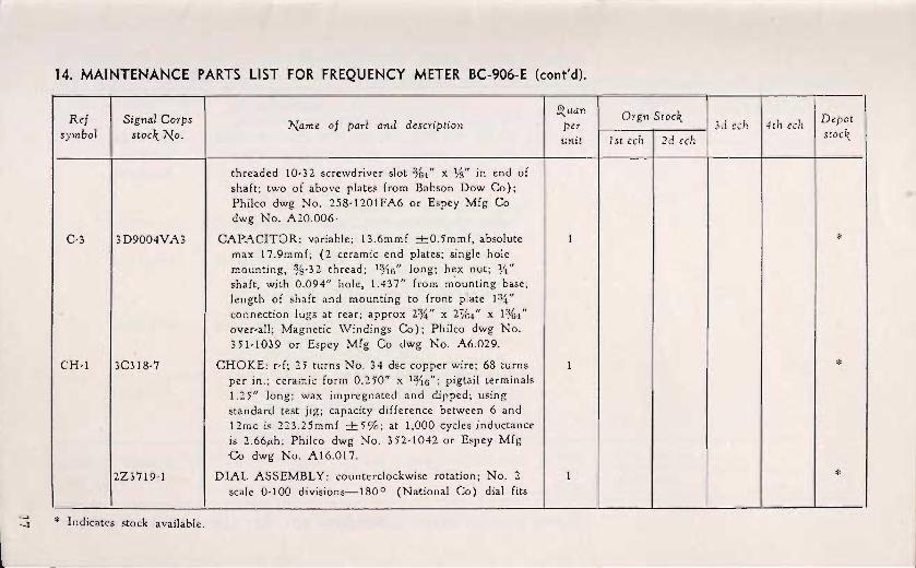
14. MAINTENANCE PARTS LIST FOR FREQUENCY METER BC-906-E (cont'd).
Ref symbol
C-3
CH-1
Signl1l Corps stocl{ No.
3D9004VA3
3-C318-7
2Z3719-1
-l * Indicates stock available.
Name of part and description
threaded 10-32 screwdriver slot %4" x l/S" in end of shaft; two of above plates from Babson Dow Co); Philco dwg No. 258-1201FA6 or Espey Mfg Co dwg No. A20.006 ·
CAPACITOR: variable; 13.6mmf -+-O.5mmf, absolute max 17.9mmf; (2 ceramic end plates; single hole mounting, %-32 thread ; 1%6" long; hex nut; %" shaft, with 0.094" hole, 1.437" from m'ounting base; length of shaft and mounting to front plate connection lugs at rear; approx 2%" x 2%4" x 1%4" over-all; Magnetic Windings Co) ; Philco dwg No. 35'1-1039 or Espey Mfg Co dwg No. A6.029.
CHOKE: r-f; 25 turns No. 34 dsc copper wire; 68 turns per in. ; ceramic form 0.250" x 1%6"; pigtail terminals 1.25" long; wax impregnated and djpped; using standard test jig; capacity difference between 6 and 12mc is 223.25mmf -+- 5%; at 1,000 cycles inductance is 2.66/Lh ; Philco dwg No. 352-1042 or Espey Mfg Co dwg No. A16.017.
DI.AL ASSEMBLY: counterclockwise rotation; No.2 scale 0-100 divisions-180 o (National Co) dial fits
Q..uan per unit
Orgn 3d eeh 14th eeh
1 st eeh I 2 d eeh
Depot stoel{
*
>;<
*

:lO 14. MAINTENANCE PARTS LIST FOR FREQUENCY METER BC-906-E (cont'd).
Ref Signal Corps .<i(uan Orgn Depot ]\(ame of part and description per 3d ech 4th ech
symbol ]\(0. unit 1st ech 2d ech
, 0.250" diam shaft; Philco dwg No. 358-1669 or Espey Mfg Co dwg No. A27.432.
. 3GI821-24 INSULATOR: fibre gla§ sheet; (Harvel varnish 2 *
coated, I1t2" x x 0.010", rectangular shape; Acme Specialty Sales Co); Philco dwg No. 257-7098 or Espey Mfg Co dwg No. A26.143
3GI770-160.1 INSULATOR: fibre glass sheet; (Harvel varnish 1 * coated, 21J:!" x %" x 0.0 I 0", rectangular shape; Acme Specialty Sales Co) ; Philco dwg No. 257-7451 or Espey Mfg Co dwg No. A26.142.
J-2 2Z 5572-ll JACK: type No. 504B, Utah Co. 1 * )-1 JACK: phone; to fit Plug P L-55; (1" x 1%2" x %-32 1 *
thread, mounting %G" long, with hex nut, single contact break, insulated; Mallory type A 2A); Philco dwg No. 358-1195.
6R57400-6 KEY: Allen hex; fits No. 6 cup-point setscrew, short 1 * arm series; Philco dwg No. 258-1632 .
3Z 12004-8.2 LU G : %" x %2" diam with %2" diam hole, hot tin 2 * dipped; type No. 2079, C jnch Mfg Co; Philco dwg N o. 5li058FE9.
- -- - ------- ---
* Indicates stock available.
'Cl
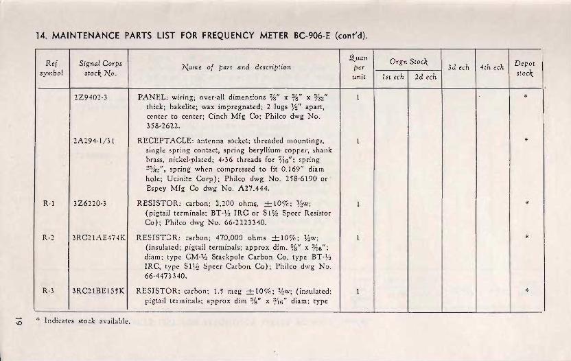
14. MAINTENANCE PARTS LIST FOR FREQUENCY METER BC-906-E (cont'd).
Ref symbol
R·l
R·2
R·3
Signal Corps stocl{ No.
2Z 9402·3
2A294-l / 31
Name of part and description
PANEL: wiring; over·all %" x ;B" X %2" thick; bakelite; wax impreg nated; 2 lugs lh" apart, center to center; Cinch Mfg Co; Philco dwg No. 358·2622.
RECEPTACLE: antenna socket; threaded mountings, single spring contact, spring beryllium· copper, shank brass, nickel·plated; 4·36 threads for Vt6"; <pring 2%2", spriog when compressed to fit 0.169" diam hole; Ucinite Corp); Philco dwg No. 258·6190 or ' Espey Mfg Co dwg No. A27.444.
3Z6220·3 RESIST OR: carbon; 2,200 ohmli, +10%; %w; (pigtail terminals; BT·% IRe or S 11h Speer Resistor Co); Philco dwg No. 66·2223340.
3RC21AE 474KI RESIST:JR: carbon; 470,000 ohms +10%; (insulated; pigtail terminals; approx dim. %" x %6"; diam; type Stackpole Carbon Co, type IRC, type S1 % Speer Carbon Co); Philco dwg No. 66·4473340.
3RC21BE155KI RESISTOR: carbon; 1.5 meg +10%; (insula ted ; pigtail terminals; approx dim %" x 0/16" diam ; type
* Indicates stock available.
per unit
Orgn S tocl{ 3d ech 4th ech
1st ech I 2d ech
Depot stocl{
'"
*
*
"'
*
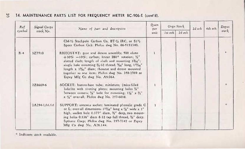
I"J o 14. MAINTENANCE PARTS LIST FOR FREQUENCY METER BC-906-E (cont'd).
Ref symbol
R·4
Signal Corps No .
3Z7510
2Z8669·6
2A294·I/sl/sl
" Indicates available .
Name of part and description
Stackpole Carbon Co. IRC, or Speer Carbon Co): Philco dwg No. 66·5153340.
RHEOSTAT: gear and detent a,sembly; 500 ohms +30% -10o/r; carbon; linear 280 0 rotation ; 1,4" slotted shaft; length of shaft and mounting l¥IG"; &ingle hole mounting %·32 thread; =¥Is" long, l l¥Is" I.::ngth x 1%2" diam; rheostat and detent mounted together as one item; Philco dwg No. 358·2769 or Espey Mfg Co dwg No. A9.064.
SOCKET: button·base tube; miniature; (mica·filled bakelite with riveting plates; mounting holes between centers; %" hole for mounting; Ilk" x %" x :!4" over·all; Philco dwg No . 257·6038.
SUPPORT: antenna socket; laminated phenolic grade C or L; over·all dimensions II:r1s" long x %;" wide xl" high, socket hole 0.377" diam, *" deep, two mount· ing holes 0.136" diam 8·32 tap full thread, %" deep; Sythane Corp; Phileo dwg No. 257·7342 or Espey Mfg Co dwg No. A26.144.
per unit
Orgn 3d ech 4th ech
Istechl2dech
Depot
:;:
:;:
*
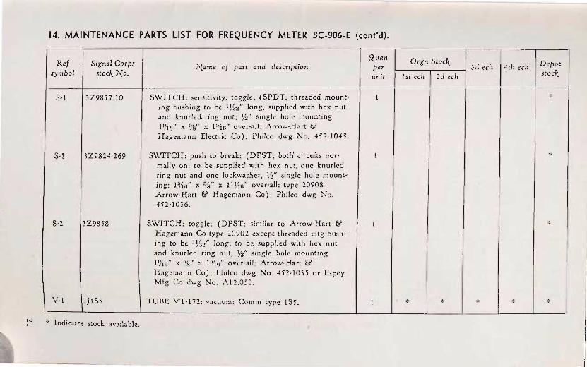
14. MAINTENANCE PARTS LIST FOR FREQUENCY METER BC-906-E (cont'd).
Ref S ignal Corps Orgn Stoc1t Depot Name of part and description per 3d cch 4th ecll .symbol No. unit 1st cch 2d ech
5-1 3Z9857.10 SWITCH: sensitivity; toggle; (SPDT; threaded mount- 1 ,;:
ing bushing to be 1%2" long, supplied with hex nut and knurled. ring nut; Y.!" single hole mounting 1 x %" x 1 over-all; l\.rrow-Hart {5 Hagemann Electric Co); Philco dwg No. 452-1045.
5-3 3Z9824-269 SWITCH: push to break; (DPST; both' circuits nor- 1 * mally on; to be supplied with hex nut, one knurled ring nut and one lockwasher, single hole mount-ing; 1 f;'tIJ" x %" x II Yt6" over-all; type 20908 Arrow·Hart {5 Hagemann Co) ; Philco dwg No. 452-1036.
5-2 3Z9858 S.WITCH: toggle ; (DPST; similar to Arrow-Hart {5 l :\:
Hagemann Co type 20902 except threaded mtg bush-ing to be ] long; to be supplied with hex nut and knurled ring nut, Y.!" single hole mounting l ry't6" x x n't6" over-all; Arrow-H art &
\ VI
Hagem ann Co); Philco dwg No. 452-1035 or Espey Mfg Co dwg No. AI2 .0S2.
2} IS; TUBE VT-I72: vacuum; Comm type IS5 . 1 :\: '" * * '" tv '" Indicates stock available.
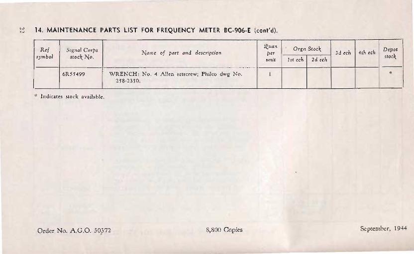
IV IV 14. MAINTENANCE PARTS LIST FOR FREQUENCY METER BC-906-E (cont'd).
Ref Signal Corps .(tuan
Name of part and description peT symbol stock,. No. unit
6R55499 WRENCH: No.4 Allen setscrew; Philco dwg No. 1 258-2350.
Indicates stock available.
Order No. A.G.O. 50}72 8,800 Copies
Drgn Stock,. Depot 3d ech 4th ech 1st ech 2d ech stock,.
*
September, 1944


TM 11-2623 C 1
RESTRICTED TECHNICAL MANUAL
FREQUENCY METER BC- 906-E
CHANGES} WAR DEPARTME T No.1 . WASHINGTON 25, D. C., 16 December 1944 TM 11- 2623, 26 July 1944, is changed as follows: Delete the fo llowing items from pages 18 and 19, paragraph 14:
3Z12004- 8.2 ...... LUG: %" x %2" diam wi'th %2" d iam hole, hot tin 2 dipped; type No. 2079, Cineh Mfg Co; Philco dwg No. 5L10 58FE9.
2Z9402- 3 ........ PANEL: wir ing; over-all dimensions %" x %" X %2"
[A. O. 300.7 (25 Oct 44)1
thick; bak lite; wax imprcgna ted; 2 lugs W' apart, cen ter to center; Cinch Mfg. Co; Philco dwg No. 358- 2622.
. By ORDER OF THE SECRETARY OF VVAR:
OFF'lCIAL:
J. A. ULIO Major General The Adjutant General
DISTRIBUTION:
G . C. MARSHALL Chief oj Sta,ff
*
*
AAF (10); AGF (10) ; ASF (2); Dept (5); Arm & Sv Bd (2); Dcf C (2); Sv C (5); ASF Dep (Sig Sec) (5); AF Dep (Sig Sec) (5); USMA (2); Proc Dists 11 (2); Insp Zones 11 (2); R ep Sh 11 (2)
T jO & E 11- 107 (2); 11-237 (2); 11- 287 (2); 11-400 Sig AW Orgn (A) Bn Hq (5), Radar R ep Pla t (U) (2); 11-500 Radar Maint Team (EC); 11- 587 (2); 11-592 (2); ' 11- 597 (2); 11-617 (2)
For explanation of symbols, see FM 21- 6.
L_---.::..... U. s. C;OHRNMENT PRINTING OFFICE : 19 ..