frequency-deviation meter serial no. - iet … frequency-deviation...general radio company = =...
TRANSCRIPT

OPERATING INSTRUCTIONS FOR
TYPE 581-B FREQUENCY-DEVIATION
METER SERIAL NO.
GENERAL RADIO COMPANY CAMBRIDGE A, MASSACHUSETTS

GENERAL RADIO COMPANY
WARNING:
BEFORE ATTEMPI'ING TO OPERATE THIS
INSTRUMENT, READ CAREFULLY THE SEGI'IONS
ON INSTALLATION AND OPERATION (PARTS 2
AND 3),
FAILURE TO DO THIS MAY RESULT IN
SERIOUS DAMAGE TO THE INSTRUMENT.
PATENT NOT ICE
The Type 581-B Frequency-Deviation Meter is manufactured and sold under United States Patent 1,944,315.
This instrument is licensed under patents of the American Telephone and Telegraph Company solely for utilization in research, investigation, measurement, testing, instruction and development work in pure and applied science.
TABLE OF CONTENTS
Page
PART I - PURPOSE - - - - - - - - - - - - - -Advantages - - - - - - - - - - - - - -Principle of Operation -Accuracy - - - - - -
PART II - INSTALLATION - -Accessories Location -Connections
PART III - OPERATING INSTRUGI'IONS Operation - - - - - - - - - -Example of Use - - - -Routine Operation -- - - - - - - -
PART IV - MAIN'l'ENANCE Maintenance - - -
l l l 3
3 3 3 4
4 4 5 5
5 5

GENERAL RADIO COMPANY = =
OPERATING INSTRUCTIONS FOR
TYPE 581-8 FREQUENCY-DEVIATION
METER
PART I PURPOSE
The Type 581-B Frequency- Deviation Meter is designed for use with the Type 575-E Piezo-Electric Oscillator to enable a radio broadcasting station to maintain its frequency to within the ~50-cycle limit specified by the Federal Radio Commission and by the Canadian Radio Broadcasting Commission.
ADVANTAGES The instrument indicates the deviation of the station
carrier frequency from its assigned value on a pointer- type meter . The scale is gr aduated in 10-cycle steps, from -100 cycles to +100 cycles, and a change of one cycle is readily discernible . As the indicator has a zero-center scale, that is, the reading of the instrument shows automatically whether the station frequency is high or low. The deviation meter, with its associated detector and amplifier circuits, is arranged for a-c operation . An
RADIO TRANSMITTER
(MASTER OSCILLATOR OR
BUFFER AMP.)
a- c operated power supply, which also supplies power to the Type 575-E Piezo Electric Oscillator, is contained in the instrument . Cables for connecting the deviation meter and monitoring oscillator are furnished,
PRINCIPLE OF OPERATION The Type 581- B Frequency- Devia
tion Meter is designed to operate from voltages derived from the unmodulated master oscillator of the transmitter and from the crystal monitor , It is essential that the transmitter be of the master-oscillator tY-Pe in which the master oscillator itself is not modulated. In modern transmitters, the master oscillator generally consists of a temperature- controlled piElZoelectric oscillator .
Figure 1 is a functional bl ock diagram showing the system of measurement , Briefly, the instrument operate~ as fol-
AUDIO DETECTOR 1-- AMPLIFIER I--
FREQUENCY
f 0 + 1000 cps
TYPE 575-E PIEZO-ELECTRIC
OSCILLATOR (FREQ U ENC Y
STANDARD)
METER
fo =ASSIGNED CARRIER FRE QUE NCY f :FREQUENCY DEVIATION FR OM ASSIGNED CH ANNEL
FIGURl' l. Schematic diagram for the frequency monltor. 'fhe "frequency standard" is operating at a frequency 1000 cycles above that of the carrier. When operating 1000 cycles below the carrier the beat frequency involved in the deviation meter is
(lOOO±f)
- 1 -
GENERAL RADIO COMPANY :::::::: =::::::::::::::
581-10
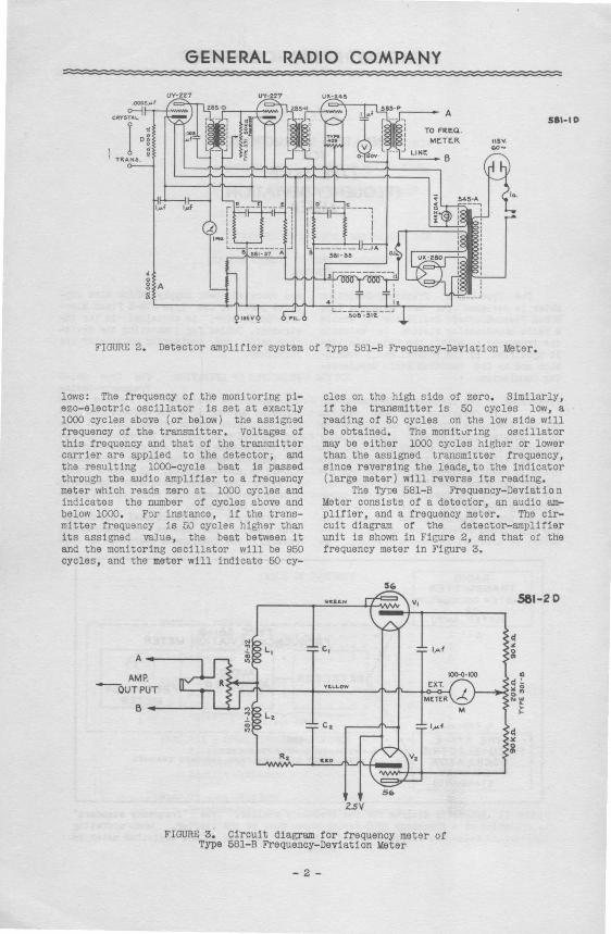
FIGURE 2. Detector amplifier system of Type 581- B Frequency- Deviation Meter .
lows : The frequency of the monitoring piezo- electric oscillator is set at exactly 1000 cycles above (or below) the assigned frequency of the transmitter . Voltages of this frequency and that of tqe transmitter carrier are applied to the detector; and the resulting 1000- cycle beat i s passed through the audio a~plifier to a frequency meter which reads zero &t 1000 cycles and indicates the number of cycles above and below 1000. For instance, if the transmitter frequency is 50 cycles higher than i ts assigned valu~, the beat between it and the monitor ing oscillator will be 950 cycles , and the meter will indicate 50 cy-
A---.., AMP.
----ouTPUT
B.-.----'
cles on the high side of zero . Similarly , i f the transmitter is 50 cycles low, a r eading of 50 cycles on the low side will be obtained. The monituring oscillator may be either 1000 cycles higher or lower than the assigned transmitter frequency , since reversing the leads. to the indicator (large meter) will reverse its reading.
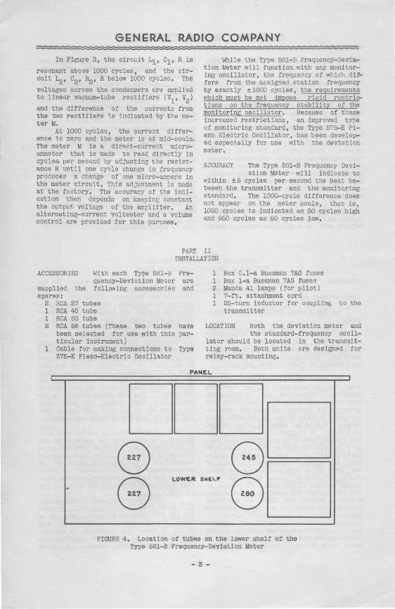
The Type 581- B Frequency- Deviation Meter consists of a detector , an audio amplifier , and a frequency meter. The circuit diagram of the detector- amplifier unit is shown in Figure 2 , and that of the frequency meter in Figure 3.
581-2.0
zsv
FIGURE 3. Circuit diagram for frequency meter of Type 581- B Frequency- Deviation Meter
- 2 -
GENERAL RADIO COMPANY
In Figure 3 , the circuit L1, c1 , R is
resonant above 1000 cycles , and the circuit L2, c2, ~· R below 1000 cycles. The
voltages across the condensers are applied to linear vacuum-tube rectifiers (v1, v2)
and the difference of the currents from the two rectifiers is indicated by the meterM.
At 1000 cycles, the current difference is zero and the meter is at mid-scale. The .meter M is a direct-current microammeter that is made to read directly in cycles. per second by adjusting the resistance R until one cycle change in frequency produces a change of one micro-ampere in the meter circuit . This adjustment is made at the factory . The accuracy of the indication then depends on keeping constant the output voltage of the amplifier . An alternating-current voltmeter and a volume control are provided for this purpose .
While the Type 581- B Frequency-Deviation Meter will function with any monitoring oscillator, the frequency of which differs from the assigned station frequency by exactly ±1000 cycles, the requirements which must be met impose rigid restriotions on the frequency stability of the monitoring oscillator , Because of these increased restri~tions, an improved type of monitoring standard, the Type 575- E Piezo Electric Oscillator , has been develop- · ed especially for use with the deviation meter .
ACCURACY The Type 581- B Frequency Devi-ation Meter will indicate to
within ± 5 cycles per second the beat between the transmitter and the monitoring standard . The 1000- cycle difference does not appear on the meter scale, that is, 1050 cycles is indicated as 50 cycles high and 950 cycles as 50 cycles low.
PART II INSTALLATION
ACCESSORIES With each Type 581-B Fre-quency- Deviation Meter are
supplied the following accessories and spares :
2 RCA 27 tubes l RCA 45 tube l RCA 80 tube 2 RCA 56 tubes (These two tubes have
been selected for use )'lith this particular instrument)
1 Cable for making connections to Type 575- E Piezo- Electric Oscillator
1 Box 0. 1-a Bussman 7AG fuses l Box 1- a Bussman 7AG fuses 2 Mazda 41 lamps (for pilot) l 7-ft . attachment cord l 25- turn inductor for coupling to the
transmitter
LOCATION Both the deviation meter and the standard-frequency oscil
lator should be located in the transmitting room. Both units are designed for relay-rack mounting .
PAN[.l.
#
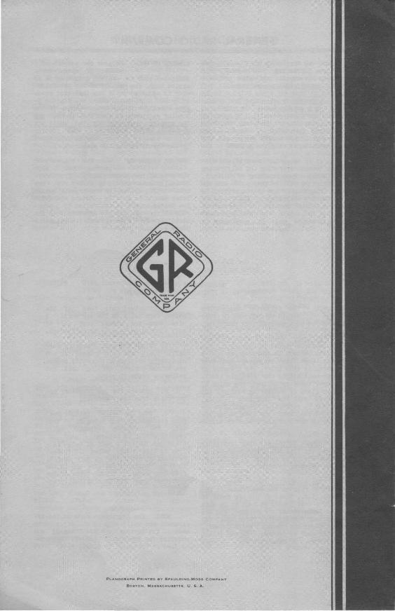
DOD 8 G 8
LOWE.Ft SIIEL.I'"
8 FIGURE 4. Location of tubes on the lower shelf of the
Type 581- B Frequency-Deviation Meter
- 3 -

GENERAL RADIO COMPANY : : : : : : :::= :=:=:=:=: : : : : : : : = =
CONNECTIONS l. Connect alternating current supply to plug recep
tacle labelled ~115 v, 60 CYCLES". Use the cord and plug supplied.
2, Connect power supply to Type 575-E Piezo-Electric Oscillator by means of the cable furnished,
3, Connect terminals marked "CRYS." to output terminals of monitoring standard oscillator. A pair of twisted leads may be used, Note that the frequency of the standard should be 1000 cycles per second lower or higher than the assigned channel frequency of the transmitter. The General Radio Type 575-E Piezo Electric Oscillator and a Type 376-J Quartz Plate are .recommended,
4, Connect terminals marked "TRANS" to the small 25-turn coil by means of a twisted pair or a shielded cable. Mount
:: : : : ; : : = ; : ; :::: :=:=
this coil ln the field of the tuning inductance of either the master oscillator or buffer amplifier or the transmitter, This coil must be coupled to the transmitter at a point where the carrier is unmodulated, The TYpe 581-A Frequency-Deviation Meter will not function properly on a modulated signal, In some cases a static shield for the coupling coil may be necessary to eliminate modulated interference from the output circuits of the transmitter, After satisfactory operation is obtained the counling coil may be mounted in position permanently,
5, The terminals engraved"EXT METER" are supplied in order that an extra indicating meter outside the transmitting room may be used it desired,* When no extra indicator ls used, these terminals are to be short-circuited, •For further information (prioea, eto.) ocmmmioate with the General Radio Compan;y .
PART III OPERATING INSTRUCTIONS FOR THE
TYPE 581-B FREQUENCY-DEVIATION METER
OPERATION With connections made as outlined in the preceding sec-
tion, proceed as follows:
1. Throw power switch to "ON" posi-tion,
2. Adjust position of transmitter coupling coil until a change in detector plate current of about 0,5 milliamperes is obtained, with carrier on and off, The coil should be fixed in this position.
3, Start crystal oscillator and adjust its controls until it is operating properly. Directions for adjusting the Type 575-E Piezo-Electric Oscillator are given in the instruction book for that instrument. A small change in detector plate current should be observed when crystal oscillator is started and stopped while the "TRANS."4erminals are short-circuited, or with station carrier off, With both crystal oscillator and transmitter operating, the output voltmeter on the panel of the Type 581-B Frequency-Deviation Meter should indicate at least 90 volts with volume control at maximum, If voltage is too low, change the coupling to the transmitter. Either too close or too loose coupling can cause low audio-frequency output ,
4, Adjust the volume control (below the output meter) until the output voltmeter reads 90 ,
5. If the station is within 100 cycles of its assigned value, the meter will indicate the frequency difference , If this station is more than 100 and less than about 200 cycles off frequency, the meter pointer will stay against the stop , If the station is more than 200 cycles off its channel, the meter may read on scale, but the indication will be false, The station should be adjusted as closely as possible before using the deviation meter . If there is any doubt as to whether or not the station is approximately correct, i.e., within 100 cycles, plug in a pair of telephones or a loud-speaker at the jack on the panel , The tone heard should be approximately 1000 cycles . In such cases this tone may be set to a 1000-cycle tuning fork or calibrated audio oscillator ,
6, When the reading varies with modulation, it indicates the presence of one of two conditions , Either the modulated voltage is picked up on the leads from the transmitter to the deviation meter, or the output stages of the transmitter are reacting on the frequency control system, Usually the former effect is the cause of the trouble.
Reversing the leads to the deviation meter from the coupling coil, grounding the deviation meter panel , plac ing a static shield around the pickup coil; any or all of these may eliminate the pickup. Avoid the use of long leads running past the transmitter output stages, A little
- 4 -

GENERAL RADIO COMPANY :::::::: ==
time spent in experiment will usually get rid or the difficulty. In general , this t r ouble is not experienced with properly designed and shielded transmitters .
7. A frequency adjusting device consisting of a potentiometer is mounted at the right or the top shelf. By means of this the point of zero frequency deviatio~ as indicated by the meter, can be varied over a range of ±20 cycles per second . The normal position is with the pointer in the center.
It is recognized tHat slight differences between operating and calibrating temperatures, rough handling in shipment, or slight aging effects may shift the operating frequency of the quartz crystal in the monitoring oscillator. The frequency adjusting device permits the operator to bring the indication into exact agreement with measurements made by government or commercial monitoring stations .
EXAMPLE OF USE Suppose the average of a number of measurements
indicates that the station frequency is 10 cycles high. The tJetting of the potent-iometer is adjusted until the indicator reads 10 cycles high, which makes the monitor ~ ~ exactly with the measurements. If the monitor equipment is then left alone, and the station frequency adjusted until the deviation meter reads zero, the station will be exactly on frequency as determined by the agency making the measurements .
ROUTINE -OPERATION When the transmitter is shut down, both
the crystal oscillator and the frequencydeviation meter should be turned off. The heat-control system on the crystal oscillator should be kept in constant operation. The heater supply is controlled by a separate switch and is not affected when the oscillator is turned oft at its filamentplate switch.
PART IV MAINTENANCE OF THE
TYPE 581-B FREQUENCY- DEVIATION METER
MAINTENANCE The following suggestions should be followed in order
to secure the most satisfactory operation.
1. Accuracy When the monttoring ·apparatus is first placed in operation, the transmitter should be operated at such a frequency that the frequency indicator reads zero . At this point, the transmitter should be well within the 50- cycle limit. If a closer check is desired, the value of frequency given by monitoring stations may be compared with the indicator reading, thus giving a correction factor for the indication. This error may then be compensated for by means of the frequency adjustment.
2. Output Voltmeter The voltmeter reading on the Type 581-B Frequency-Deviation Meter should be held at 90 volts, readjusting whenever necessary.
3. Replacement of Tubes When it is necessary to replace the two frequency meter tubes, i.e ., those on the top shelf of the unit, a test should be made to be sure that the replacements are matched and are of the proper sensitivity. These tubes can be supplied by the General Radio Company, or, if the user so desires, he may select his own tubes . To make this test, proceed as follows:
a. Short-circuit both of the wooden form coils on the top shelf. A wire connected across each pair of coil binding posts will be sufficient .
b. With the unit operating normally, i . e., with both transmitter and monitoring oscillator connected,change the volume-control setting until the voltmeter reads 60 volts ,
c. Remove the two frequency meter tubes from their sockets .
d. Into one socket (either one) plug successively the tubes to be tested . The frequency indicator scale reading should be between and divisions . Select a pair of tubes falling in this range whose individual readings do not differ by more than 5. These are satisfactory for use in the freql''3ncy meter . Normal tubes of the specified type are usually satisfactory.
NOTE : The guarantees made on the instrument are valid only if the adjustments made at the factory are not changed, and provided the instrument has not been mishandled or subjected to abuse .
- 5 -
Pt..ANOGFIAF>H PRINTEO BY SPAUL.OING·MOSS COMPAN'f
BOSTON, MASSACHUSETTS , U , 5. A.