freespeak ii base station system - partyline · page 1 399g169 rev c october 09 2017 freespeak ii®...
TRANSCRIPT
Page 1 399G169 Rev C October 09 2017
FreeSpeak II® Base Station system
Part Number: 399G169 Rev C
Date: October 09, 2017
User
Guide
Page 2 399G169 Rev C October 09 2017
Document Reference
Clear-Com FreeSpeak II User Guide
Part Number: 399G169 Rev C
Legal Disclaimers
Copyright © 2017 HME Clear-Com Ltd.
All rights reserved.
Clear-Com and the Clear-Com logo are registered trademarks of HM
Electronics, Inc.
The software described in this document is furnished under a license
agreement and may be used only in accordance with the terms of the
agreement.
The product described in this document is distributed under licenses
restricting its use, copying, distribution, and decompilation/reverse engineering. No part of this document may be reproduced in any form by any
means without prior written authorization of Clear-Com, an HME Company.
Clear-Com Offices are located in California, USA; Cambridge, UK; Dubai,
UAE; Montreal, Canada; and Beijing, China. Specific addresses and contact
information can be found on Clear-Com’s corporate website:
www.clearcom.com
Clear-Com Contacts
Americas and Asia-Pacific Headquarters
California, United States
Tel: +1.510.337.6600
Email: [email protected]
Europe, Middle East, and Africa Headquarters
Cambridge, United Kingdom
Tel: +44 1223 815000
Email: [email protected]
China Office
Beijing Representative Office
Beijing, P.R.China
Tel: +8610 65811360 / 65815577
Page 3 399G169 Rev C October 09 2017
Table of Contents
Document Reference .............................................................. 2
1 What is FreeSpeak II Base? .................................. 6
1.1 2-wire, 4-wire and wireless intercom .......................... 6
1.2 Flexible configuration ................................................ 7
1.3 Live set-up and control ............................................. 7
1.4 System capacity ...................................................... 8
2 Using the Base Station .......................................... 9
2.1 About the Base Station ............................................. 9
2.2 Base Station front panel ............................................ 9
2.3 What is a Keyset? .................................................. 10
2.4 FreeSpeak II Base rear connectors ........................... 12
2.5 Base Station rear connector pinouts .......................... 13
2.6 FreeSpeak II Base Station menu 'at-a-glance' guide .... 15
2.7 Networking/IP issues .............................................. 17
2.8 Base Station menu overview .................................... 19
3 Installing the antennas ....................................... 21
3.1 Introduction .......................................................... 21
3.2 Site survey ........................................................... 24
3.3 Standalone site survey ........................................... 25
3.4 Using an antenna with a Fiber connection .................. 27
3.5 Interpreting the Site Survey screen ........................... 28
3.6 How to put a beltpack into Site Survey mode ............. 29
3.7 Cable compensation ............................................... 30
4 Using the antennas ............................................. 33
4.1 Introduction .......................................................... 33
4.2 Antenna connectors ................................................ 34
4.3 FreeSpeak II Base 1.9 GHz/2.4 GHz ......................... 35
Page 4 399G169 Rev C October 09 2017
4.4 Radio frequency (RF) issues .................................... 35
5 Using the FreeSpeak II Splitter (FSII-SPL) ......... 37
5.1 Introduction .......................................................... 37
5.2 Splitter front panel ................................................. 39
5.3 Splitter rear connectors .......................................... 40
5.4 Splitter software version ......................................... 40
6 Using Beltpacks .................................................. 42
6.1 Registering Beltpacks ............................................. 42
6.2 Unregistering Beltpacks .......................................... 46
6.3 Assign channels to Beltpack keys ............................. 47
6.4 Beltpack default settings ......................................... 52
7 Beltpack features ............................................... 55
7.1 Menu key operation ................................................ 55
7.2 Master volume low level limiter (beltpacks) ................ 57
7.3 Configurable eavesdropping ..................................... 58
7.4 AA Battery Type: Alkaline/NiMh ................................ 59
7.5 Using the beltpack functions .................................... 60
8 Roles ................................................................... 63
8.1 About FreeSpeak II Base Roles ................................ 63
8.2 Default Role settings .............................................. 63
8.3 Changing Channels on beltpacks .............................. 64
8.4 Change beltpack settings ........................................ 67
8.5 How to create Roles for beltpacks ............................. 67
8.6 Save Settings ........................................................ 69
8.7 Fixed Roles ........................................................... 71
9 Core Configuration Manager (CCM) ..................... 74
9.1 How to access the CCM ........................................... 74
9.2 CCM walkthrough ................................................... 75
10 Configuring audio routes ..................................... 81
10.1 About audio routes ................................................. 81
Page 5 399G169 Rev C October 09 2017
10.2 Example audio assignment ...................................... 86
10.3 Change key assignments on the Base Station ............. 91
10.4 Configure a one-to-one connection ........................... 93
11 Connecting different systems .............................. 94
11.1 Interconnection ..................................................... 94
11.2 Connecting FreeSpeak II Base to other intercom devices
........................................................................... 94
11.3 Connecting 2-wire equipment .................................. 94
11.4 Connecting to 4-wire equipment ............................... 95
11.5 Port function (to matrix or to panel) ......................... 95
12 Upgrading devices .............................................. 98
12.1 About upgrading devices ......................................... 98
12.2 How to upgrade your devices ................................... 98
13 Powering your system ...................................... 100
13.1 Powering the FreeSpeak II™ Base .......................... 100
13.2 Powering wireless beltpacks .................................. 100
13.3 Power 2-wire beltpacks from the Partyline ............... 100
13.4 Powering the transceiver antennas ......................... 100
13.5 Powering the Antenna Splitter ................................ 101
13.6 Recommended powering and cable lengths for a
FreeSpeak II Base System .................................... 101
14 Regulatory compliance ...................................... 103
15 Specifications .................................................... 107
15.1 FreeSpeak II Base Station ..................................... 107
15.2 FreeSpeak II Beltpack ........................................... 109
15.3 FreeSpeak II Transceiver/Antenna .......................... 110
15.4 FreeSpeak II Transceiver/Antenna Splitter ............... 110
15.5 Transmission Method ............................................ 111
Page 6 399G169 Rev C October 09 2017
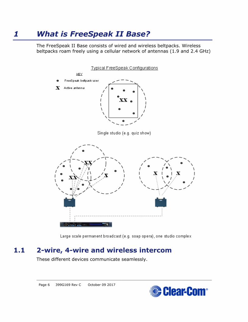
1 What is FreeSpeak II Base?
The FreeSpeak II Base consists of wired and wireless beltpacks. Wireless
beltpacks roam freely using a cellular network of antennas (1.9 and 2.4 GHz)
1.1 2-wire, 4-wire and wireless intercom
These different devices communicate seamlessly.

Page 7 399G169 Rev C October 09 2017
1.2 Flexible configuration
Pre-configured beltpack Roles allow both rapid set-up and flexible
configuration.
• Use simple default set-up; all beltpacks on Channel 1 and 2
• Customize the set-up to suit your needs.
• System has either 25 (FSII-BASE-II) or 5 (FSII-BASE-II-5) beltpack
Roles. FSII-BASE-II-5 offers a license to upgrade to 25 beltpacks if
required.
1.3 Live set-up and control
Use the front panels of the Base Station, or the browser-based Core
Configuration Manager (CCM).
Press Menu button on the Base Station to access controls:
Browser-based Core Configuration Manager (CCM), accessed via device IP
address.
Page 8 399G169 Rev C October 09 2017
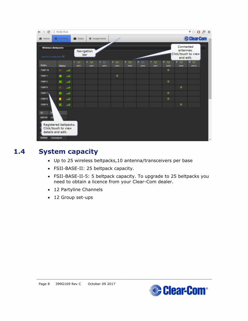
1.4 System capacity
• Up to 25 wireless beltpacks,10 antenna/transceivers per base
• FSII-BASE-II: 25 beltpack capacity.
• FSII-BASE-II-5: 5 beltpack capacity. To upgrade to 25 beltpacks you
need to obtain a licence from your Clear-Com dealer.
• 12 Partyline Channels
• 12 Group set-ups
Page 9 399G169 Rev C October 09 2017
2 Using the Base Station
2.1 About the Base Station
The FreeSpeak II Base Station routes communication to and from wireless
beltpacks. It provides a control point for audio and allows the user to configure the system, either from the front panel menus or using the online
configuration manager.
• Press Menu button to configure from the Base.
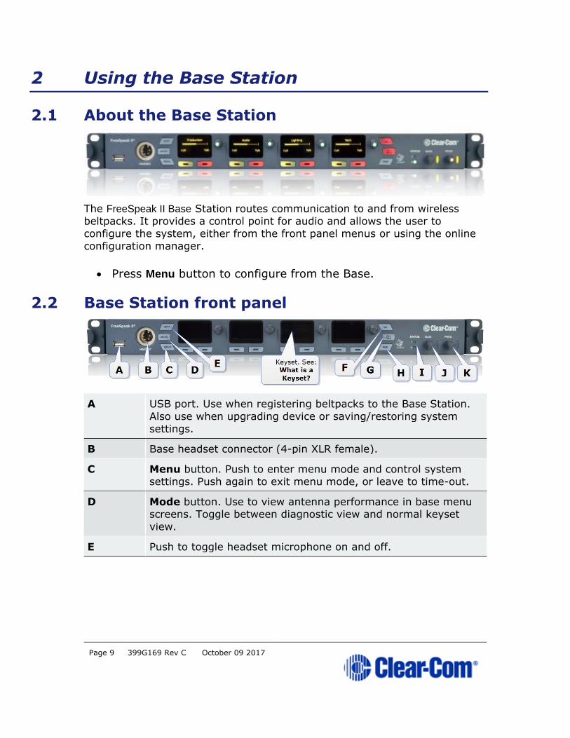
2.2 Base Station front panel
A USB port. Use when registering beltpacks to the Base Station.
Also use when upgrading device or saving/restoring system
settings.
B Base headset connector (4-pin XLR female).
C Menu button. Push to enter menu mode and control system settings. Push again to exit menu mode, or leave to time-out.
D Mode button. Use to view antenna performance in base menu screens. Toggle between diagnostic view and normal keyset
view.
E Push to toggle headset microphone on and off.

Page 10 399G169 Rev C October 09 2017
Keyset A Keyset is a set of controls associated with an audio
assignment. On the Base, a Keyset is made up of a viewing
screen and three controls (a rotary and two push buttons). The
viewing screen shows a Channel and any associated messages.
The rotary controls volume to that Channel, and the push buttons control Call and Talk to the Channel. The viewing
screens are also used to display menu and mode information.
F Stage Announce. Allows the Base operator to talk on the Stage
Announce output. Push and hold to talk. Pressing the SA button
on the Base triggers a relay which can be sent to an external
device
G All Talk. Allows the Base operator to talk to all wired and
wireless beltpacks (2-Wire and 4-Wire). Push and hold to talk.
H Remote Mic Kill (RMK). Allows Base operator to remotely
unlatch all beltpack talk keys, wireless and wired.
I Status LED 1 = Antenna warning light. If green, all antennas
are online. Status LED 2 = Beltpack warning light. If green all
BPs have sufficient battery power. If either light is amber (or
red), you can press the mode button to check the issue in the
diagnostics screens.
J Controls overall volume to the Base headset. This includes
Channels, program feed and any other available audio. Turn
rotary to adjust volume, push to turn headset sound on and off.
K Program feed to Base headset volume and control. Turn rotary
to adjust volume, push to turn feed on and off. (Does not affect
program feed in Channels).
2.3 What is a Keyset?
A Keyset is a set of controls associated with an audio assignment. The Base
Station has 4 audio assignments (Keysets), and a beltpack has two main
audio assignments (Keysets).
2.3.1 Main Station Keysets
The Keyset on the Base Station is made up of four viewing screens, each
with an associated rotary controller, a Call key and a Talk key. These controls
display and regulate the audio routes associated with the Base. As well as

Page 11 399G169 Rev C October 09 2017
controlling audio assignments, the viewing screens display menu options and
wireless diagnostics.
2.3.2 Beltpack Keysets
The Keyset on a beltpack has one screen and two sets of controls, to the left
and right of the screen. The main assignments are on keys A and B, and subsidiary assignments are on C and D. Additionally, the Reply key can be
over-ridden with an audio assignment. The default set-up for a beltpack puts
Channel 1 on keys A and C, and Channel 2 on keys B and D.
Page 12 399G169 Rev C October 09 2017
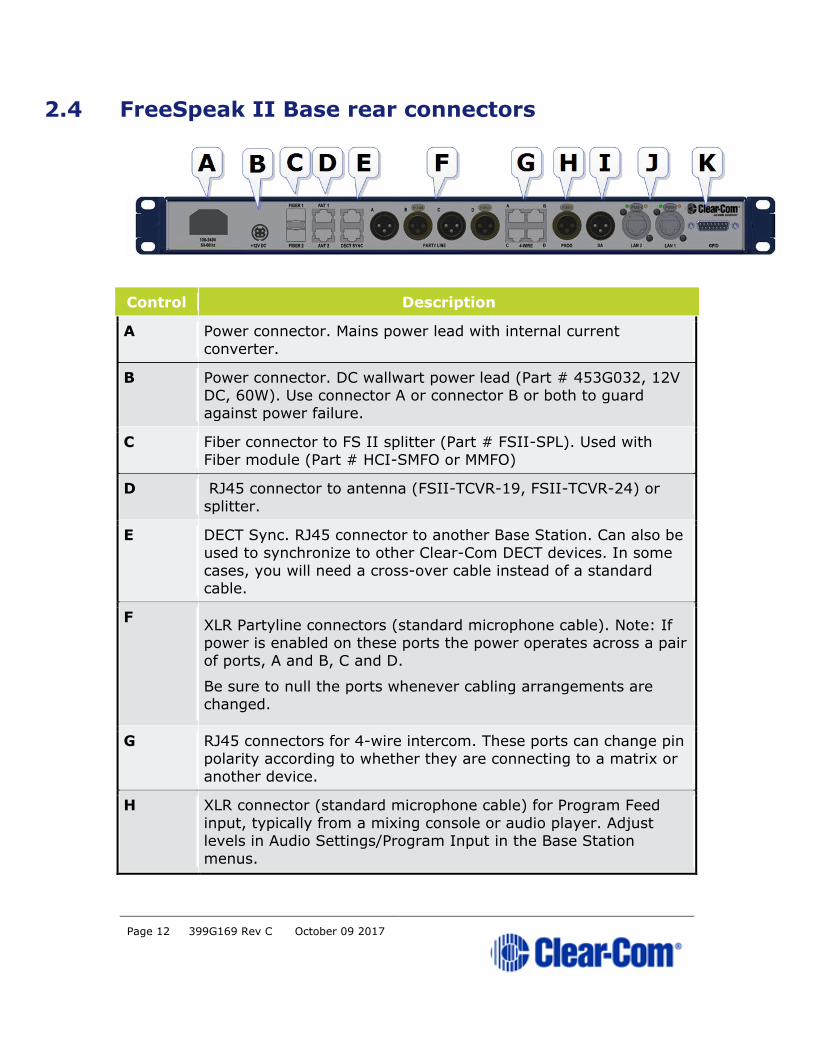
2.4 FreeSpeak II Base rear connectors
Control Description
A Power connector. Mains power lead with internal current
converter.
B Power connector. DC wallwart power lead (Part # 453G032, 12V
DC, 60W). Use connector A or connector B or both to guard against power failure.
C Fiber connector to FS II splitter (Part # FSII-SPL). Used with
Fiber module (Part # HCI-SMFO or MMFO)
D RJ45 connector to antenna (FSII-TCVR-19, FSII-TCVR-24) or
splitter.
E DECT Sync. RJ45 connector to another Base Station. Can also be
used to synchronize to other Clear-Com DECT devices. In some
cases, you will need a cross-over cable instead of a standard cable.
F XLR Partyline connectors (standard microphone cable). Note: If
power is enabled on these ports the power operates across a pair
of ports, A and B, C and D.
Be sure to null the ports whenever cabling arrangements are
changed.
G RJ45 connectors for 4-wire intercom. These ports can change pin
polarity according to whether they are connecting to a matrix or
another device.
H XLR connector (standard microphone cable) for Program Feed
input, typically from a mixing console or audio player. Adjust
levels in Audio Settings/Program Input in the Base Station
menus.

Page 13 399G169 Rev C October 09 2017
Control Description
I XLR connector (standard microphone cable) for Stage Announce output.
J 2 x RJ45 ports. These can be used for network connection or for
daisy-chaining devices. Note: The ports share an IP address, so only one network connection is possible (either port can be
used).
K GPIO connector.
Note: For connection between the Base and antenna/splitter and digital audio
feeds, Clear-Com recommends shielded Cat 5/6 cable. Use of other cable
can result in shorter cable runs and other performance problems.
2.5 Base Station rear connector pinouts
2.5.1 DECT SYNC (connector E)
Pin Sync In Sync Out
Pin 1 DECTSYNC + DECTSYNC +
Pin 2 DECTSYNC - DECTSYNC -
Pin 3 8 KHZ+ 8 KHZ+
Pin 6 8 KHZ- 8 KHZ-
2.5.2 Partyline (connectors F)
Pin Description
Pin 1 Ground (shield)
Pin 2 Power
Pin 3 Audio
Page 14 399G169 Rev C October 09 2017
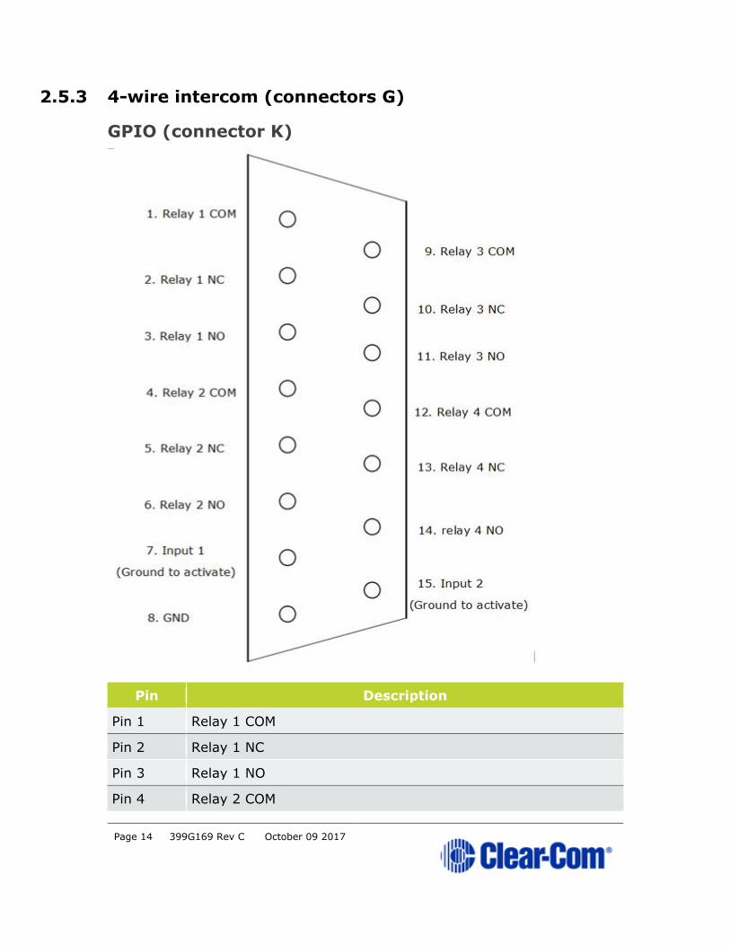
2.5.3 4-wire intercom (connectors G)
GPIO (connector K)
Pin Description
Pin 1 Relay 1 COM
Pin 2 Relay 1 NC
Pin 3 Relay 1 NO
Pin 4 Relay 2 COM

Page 15 399G169 Rev C October 09 2017
Pin Description
Pin 5 Relay 2 NC
Pin 6 Relay 2 NO
Pin 7 Input 1 (Ground to activate)
Pin 8 GND
Pin 9 Relay 3 COM
Pin 10 Relay 3 NC
Pin 11 Relay 3 NO
Pin 12 Relay 4 COM
Pin 13 RELAY 4 NC
Pin 14 RELAY 4 NO
Pin 15 Input 2 (Ground to activate)
2.6 FreeSpeak II Base Station menu 'at-a-glance' guide
2.6.1 Audio Settings:
• Headset
• Program input
• Stage announce
2.6.2 Station settings:
• Program audio on Base Station Keysets (1-4)
• Display settings
• Make Base headset a Group Member (listen to group announcements)
Page 16 399G169 Rev C October 09 2017
2.6.3 Channels
• Change Channel name (label)
2.6.4 Groups
• Change Group name (label)
2.6.5 4-wire audio
• Program audio for 4-wire (Ports 1-4)
2.6.6 2-wire audio, A and B, C and D.
• Program audio for 2-wire (Ports A and B, C and D)
2.6.7 Key Assign
• Select each beltpack (Role) and program/edit audio on keys (A, B, C,
D)
2.6.8 Beltpacks
• Change beltpack Role
• Unregister beltpacks
• Check beltpack software version
• Fix beltpack Role
2.6.9 Roles
• Create, clone and delete Roles
• Edit Role settings, e.g. change channel, alter volume, set menu
access etc.
2.6.10 Antennas
• Change antenna name (label)
• Set cable compensation if required
2.6.11 Networking
• Station id (name)
• DHCP or Static IP
• Base station IP address
Page 17 399G169 Rev C October 09 2017
2.6.12 Administration
• Beltpacks: start over-the-air registration
• Software: View version and upgrade
• License: View license and upgrade
• Reset to factory settings and save/restore settings
• Change menu access pin code
• Set AA battery type
2.7 Networking/IP issues
2.7.1 Dynamic Host Configuration Protocol
The FreeSpeak II Base is set to DHCP by default. For fast set-up, DHCP is the
best option to use as the Base Station can be immediately connected to any
network which provides DHCP. Most networks allocate IP addresses using
DHCP. The addresses provided are dynamic and will change from time to
time.
2.7.2 Static IP configuration
If your intercom installation becomes permanent, obtain a static IP address
to avoid the Base IP address from changing periodically.
When linking multiple Bases across a network or networks static IP
addressing is essential. Your network administrator should provide details.
2.7.3 Netmask or subnet
The netmask or subnet divides the network into sectors for more efficient
routing and is required when allocating a static IP address to a Base Station.
Your network administrator should provide details.
2.7.4 Gateway
This setting is optional. It is required if your system navigates across subnets
(as might be the case when accessing the CCM across networks, or linking systems). If not explicitly stated, Gateway will revert to the device IP
address.
2.7.5 Set static IP details for Base Station
From the CCM:

Page 18 399G169 Rev C October 09 2017
From the Base Station
Disable DHCP:
Enter static IP address
Page 19 399G169 Rev C October 09 2017
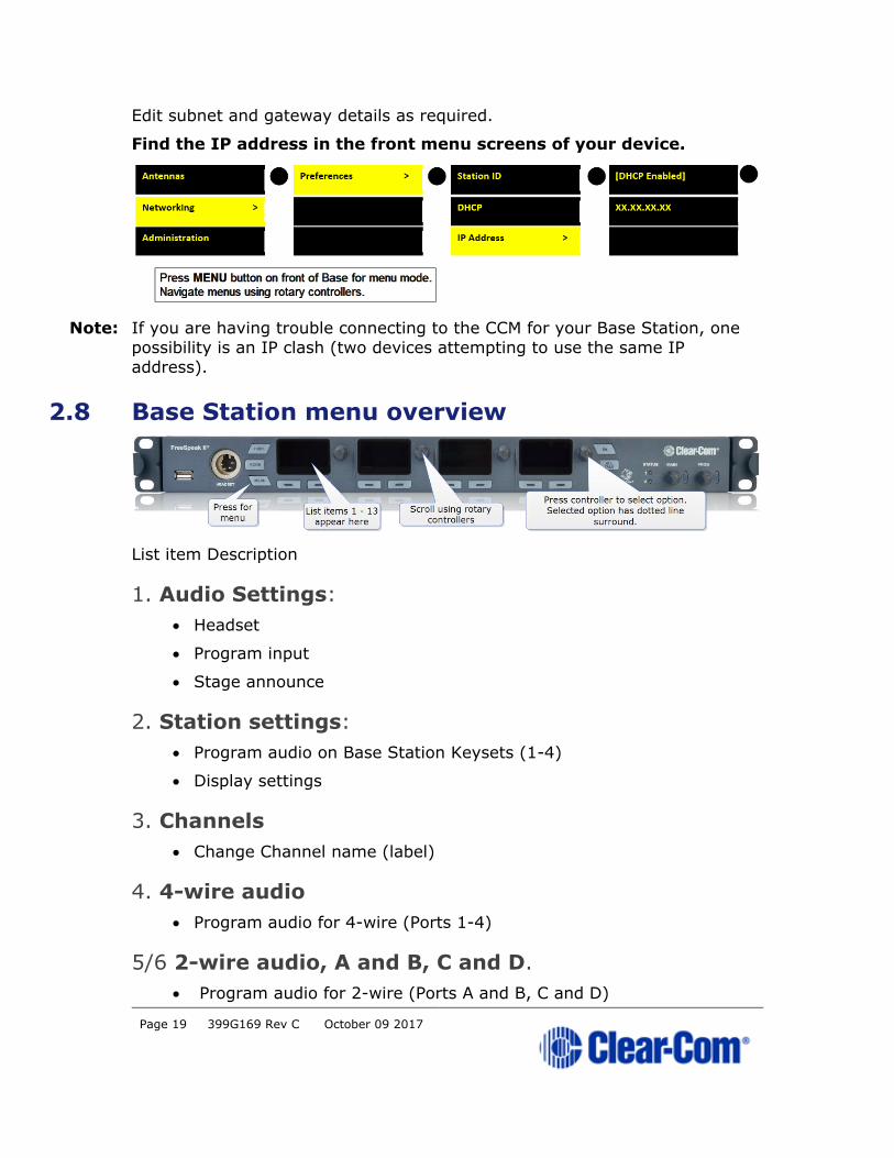
Edit subnet and gateway details as required.
Find the IP address in the front menu screens of your device.
Note: If you are having trouble connecting to the CCM for your Base Station, one
possibility is an IP clash (two devices attempting to use the same IP
address).
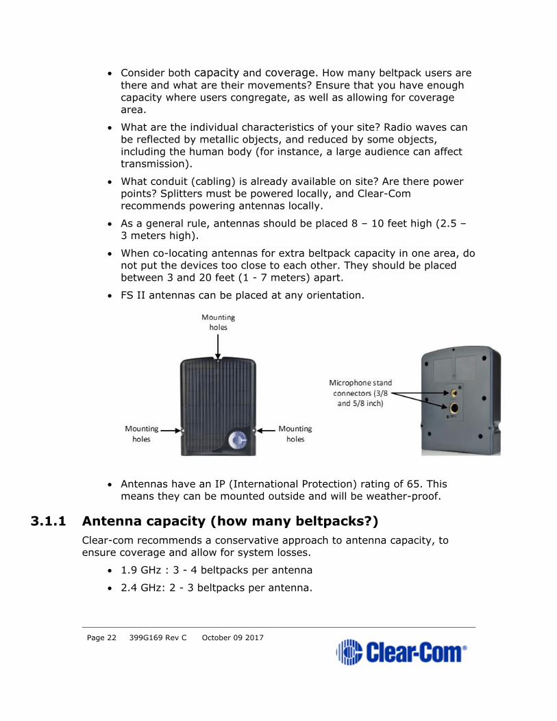
2.8 Base Station menu overview
List item Description
1. Audio Settings:
• Headset
• Program input
• Stage announce
2. Station settings:
• Program audio on Base Station Keysets (1-4)
• Display settings
3. Channels
• Change Channel name (label)
4. 4-wire audio
• Program audio for 4-wire (Ports 1-4)
5/6 2-wire audio, A and B, C and D.
• Program audio for 2-wire (Ports A and B, C and D)

Page 20 399G169 Rev C October 09 2017
6. Key Assign
• Select each beltpack (Role) and program/edit audio on keys (A, B, C,
D)
7. Beltpacks
• Change beltpack Role
• Unregister beltpacks
• Check beltpack software version
8. Roles
• Create, clone and delete Roles
9. Antennas
• Change antenna name (label)
• Set cable compensation if required
10. Networking
• Station id (name)
• DHCP or Static IP (DHCP recommended)
• Base station IP address
11. Administration
• Beltpacks: start over-the-air registration
• Software: View version and upgrade
• License: View license and upgrade

Page 21 399G169 Rev C October 09 2017
3 Installing the antennas
3.1 Introduction
Each FreeSpeak II Base has capacity for 25 beltpacks and up to 10 antennas
(using two splitters). You need to place antennas to create a custom coverage zone to suit your requirements, taking into account the physical
environment and beltpack user needs.
Things to take into account include:
Page 22 399G169 Rev C October 09 2017
• Consider both capacity and coverage. How many beltpack users are
there and what are their movements? Ensure that you have enough
capacity where users congregate, as well as allowing for coverage
area.
• What are the individual characteristics of your site? Radio waves can
be reflected by metallic objects, and reduced by some objects,
including the human body (for instance, a large audience can affect
transmission).
• What conduit (cabling) is already available on site? Are there power points? Splitters must be powered locally, and Clear-Com
recommends powering antennas locally.
• As a general rule, antennas should be placed 8 – 10 feet high (2.5 –
3 meters high).
• When co-locating antennas for extra beltpack capacity in one area, do not put the devices too close to each other. They should be placed
between 3 and 20 feet (1 - 7 meters) apart.
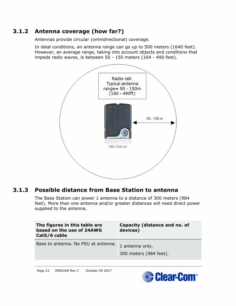
• FS II antennas can be placed at any orientation.
• Antennas have an IP (International Protection) rating of 65. This
means they can be mounted outside and will be weather-proof.
3.1.1 Antenna capacity (how many beltpacks?)
Clear-com recommends a conservative approach to antenna capacity, to
ensure coverage and allow for system losses.
• 1.9 GHz : 3 - 4 beltpacks per antenna
• 2.4 GHz: 2 - 3 beltpacks per antenna.
Page 23 399G169 Rev C October 09 2017
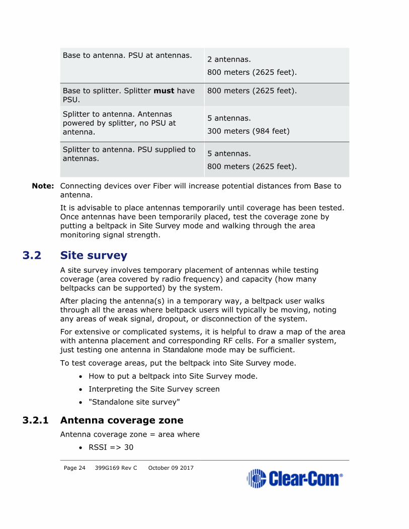
3.1.2 Antenna coverage (how far?)
Antennas provide circular (omnidirectional) coverage.
In ideal conditions, an antenna range can go up to 500 meters (1640 feet).
However, an average range, taking into account objects and conditions that
impede radio waves, is between 50 - 150 meters (164 - 490 feet).
3.1.3 Possible distance from Base Station to antenna
The Base Station can power 1 antenna to a distance of 300 meters (984 feet). More than one antenna and/or greater distances will need direct power
supplied to the antenna.
The figures in this table are
based on the use of 24AWG
Cat5/6 cable
Capacity (distance and no. of
devices)
Base to antenna. No PSU at antenna. 1 antenna only.
300 meters (984 feet).
Page 24 399G169 Rev C October 09 2017
Base to antenna. PSU at antennas. 2 antennas.
800 meters (2625 feet).
Base to splitter. Splitter must have
PSU.
800 meters (2625 feet).
Splitter to antenna. Antennas powered by splitter, no PSU at
antenna.
5 antennas.
300 meters (984 feet)
Splitter to antenna. PSU supplied to antennas.
5 antennas.
800 meters (2625 feet).
Note: Connecting devices over Fiber will increase potential distances from Base to
antenna.
It is advisable to place antennas temporarily until coverage has been tested.
Once antennas have been temporarily placed, test the coverage zone by
putting a beltpack in Site Survey mode and walking through the area
monitoring signal strength.
3.2 Site survey
A site survey involves temporary placement of antennas while testing
coverage (area covered by radio frequency) and capacity (how many
beltpacks can be supported) by the system.
After placing the antenna(s) in a temporary way, a beltpack user walks through all the areas where beltpack users will typically be moving, noting
any areas of weak signal, dropout, or disconnection of the system.
For extensive or complicated systems, it is helpful to draw a map of the area
with antenna placement and corresponding RF cells. For a smaller system,
just testing one antenna in Standalone mode may be sufficient.
To test coverage areas, put the beltpack into Site Survey mode.
• How to put a beltpack into Site Survey mode.
• Interpreting the Site Survey screen
• "Standalone site survey"
3.2.1 Antenna coverage zone
Antenna coverage zone = area where
• RSSI => 30

Page 25 399G169 Rev C October 09 2017
• Link Quality => 3
for all beltpacks.
Adjust antenna placement to get the best coverage. Coverage zones should
be overlapped. Example coverage zones are shown below.
3.3 Standalone site survey
You might need to scope a site (check the range and performance of an
antenna) without connecting to a Base Station. To do this a beltpack and
antenna can be connected in Standalone mode.
Make sure you have to hand:
• A powered beltpack
• An antenna
• A DC in XLR (male) power connector for the antenna
• Access to a power socket.

Page 26 399G169 Rev C October 09 2017
3.3.1 Setting standalone mode
1) Connect power to the antenna and at the same time press the black
Mode button on the base of the antenna. This puts the antenna in
standalone mode, and opens it for pairing to a beltpack.
Note: The amber LED flashes continuously to show that the antenna is open for
pairing with a beltpack in standalone mode.
2) Holding the beltpack, press the Menu key (2 second press) and
navigate to System Connect using the right hand rotary controller
on the beltpack.
3) Press button D to see local systems available for connection.
Note: In menu mode the D key on the beltpack operates as SELECT and the C key
exits the menu level and cancels the selection.

Page 27 399G169 Rev C October 09 2017
4) Scroll through available systems using the right hand rotary
controller.
5) When you have found the antenna to pair to (it will be showing a 'P'
to indicate that it is open for pairing) press button D to select the
antenna and connect the beltpack to it.
6) When the beltpack is successfully connected to the antenna, navigate
to Site Survey in the beltpack menu and monitor the range and
performance of the antenna. See Interpret the Site Survey Screen
below.
3.4 Using an antenna with a Fiber connection
3.4.1 Install Fiber modules (parts HLI-SMFO, HLI-MMFO
You may wish to connect a FreeSpeak II Base to a splitter (FSII-SPL) using Fiber. In this case, you need to install Fiber modules to the Base and the
splitter.
• Modules are available for single mode Fiber cable (HLI-SMFO) and
multi-mode Fiber cable (HLI-MMFO)
• Modules are supplied as a pair, one for the Base Station and one for
the splitter.
• The Base Station switches between Fiber and RJ45 mode
automatically, depending on which connector (Fiber or RJ45) is used
• Modules can be hot patched, no need to power off devices.
Page 28 399G169 Rev C October 09 2017
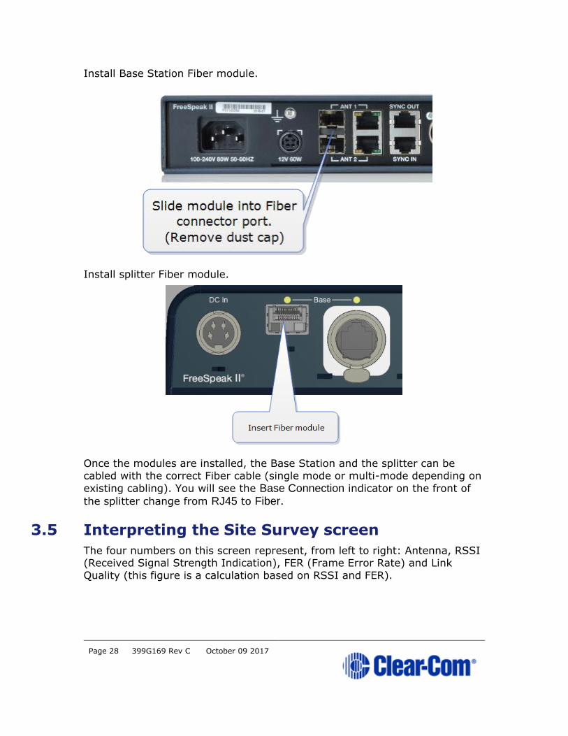
Install Base Station Fiber module.
Install splitter Fiber module.
Once the modules are installed, the Base Station and the splitter can be cabled with the correct Fiber cable (single mode or multi-mode depending on
existing cabling). You will see the Base Connection indicator on the front of
the splitter change from RJ45 to Fiber.
3.5 Interpreting the Site Survey screen
The four numbers on this screen represent, from left to right: Antenna, RSSI (Received Signal Strength Indication), FER (Frame Error Rate) and Link
Quality (this figure is a calculation based on RSSI and FER).

Page 29 399G169 Rev C October 09 2017
3.5.1 Antenna coverage zone
The antenna coverage zone is the area where:
• RSSI => 30
• Link Quality => 3
FER should be as close to 0 as possible.
Below these figures, the beltpacks may start to lose audio. All beltpacks in the
system must have sufficient ratings.
Note: You can press the Mode button on the front of the Base Station to check
antenna performance at any time.
3.6 How to put a beltpack into Site Survey mode
1) The beltpack must have advanced menu access (set menu access in
Roles/Beltpack Role/Menu Access from Base Station menus or
the CCM).
2) Press and hold the Menu button on the beltpack for 2 seconds to
enter menu mode.
3) Navigate to Site Survey in the Master menu using rotary controllers
to scroll through menu options. Site survey is at the bottom of the
Master menu.
4) Press D key to select Site Survey. Use C key to go back or cancel.

Page 30 399G169 Rev C October 09 2017
3.7 Cable compensation
You must set cable compensation if the total cable length between antennas
is greater than 500m/1640 feet.
3.7.1 About cable compensation
Cable length needs to be calculated when the distance in total cable length
between antennas is greater than 500m/1640 feet. This is to prevent the
DECT signals between antennas from becoming out of synchronization. If the
antennas are not synchronized, beltpack handover will not happen
effectively.
Setting cable compensation is particularly important if you have overlapping
antenna coverage zones (RF cells) or the beltpacks need to move between
coverage zones.
Example
Antenna 1: total cable length = 300m/984 feet.
Antenna 2: total cable length = 850m/2788 feet.
In this case, antenna cable length should be set.

Page 31 399G169 Rev C October 09 2017
How to set cable length in the CCM: 1.
Page 32 399G169 Rev C October 09 2017
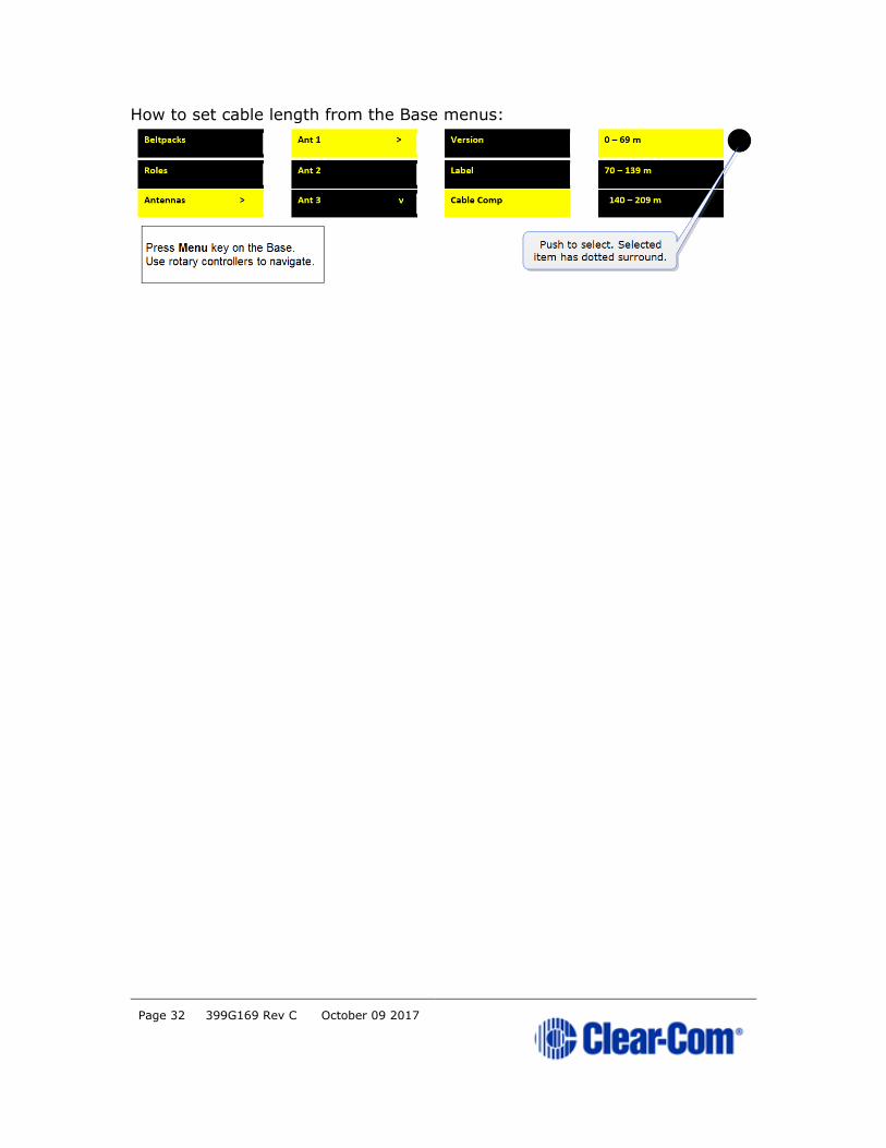
How to set cable length from the Base menus:

Page 33 399G169 Rev C October 09 2017
4 Using the antennas
4.1 Introduction
The antennas provide a customizable network of coverage zones in which
beltpacks can operate. Beltpacks can roam freely between zones.
Antennas can be mounted flat on a wall or using a microphone stand.

Page 34 399G169 Rev C October 09 2017
4.1.1 Antenna capacity (how many beltpacks?)
Clear-com recommends a conservative approach to antenna capacity, to
ensure coverage and allow for system losses.
1.9 GHz : 3 - 4 beltpacks per antenna
2.4 GHz: 2 - 3 beltpacks per antenna.
4.1.2 IP rating (international protection marking)
The antenna has an IP rating of 65 so it can be mounted outside and will be
resistant to weather conditions.
4.2 Antenna connectors
Page 35 399G169 Rev C October 09 2017
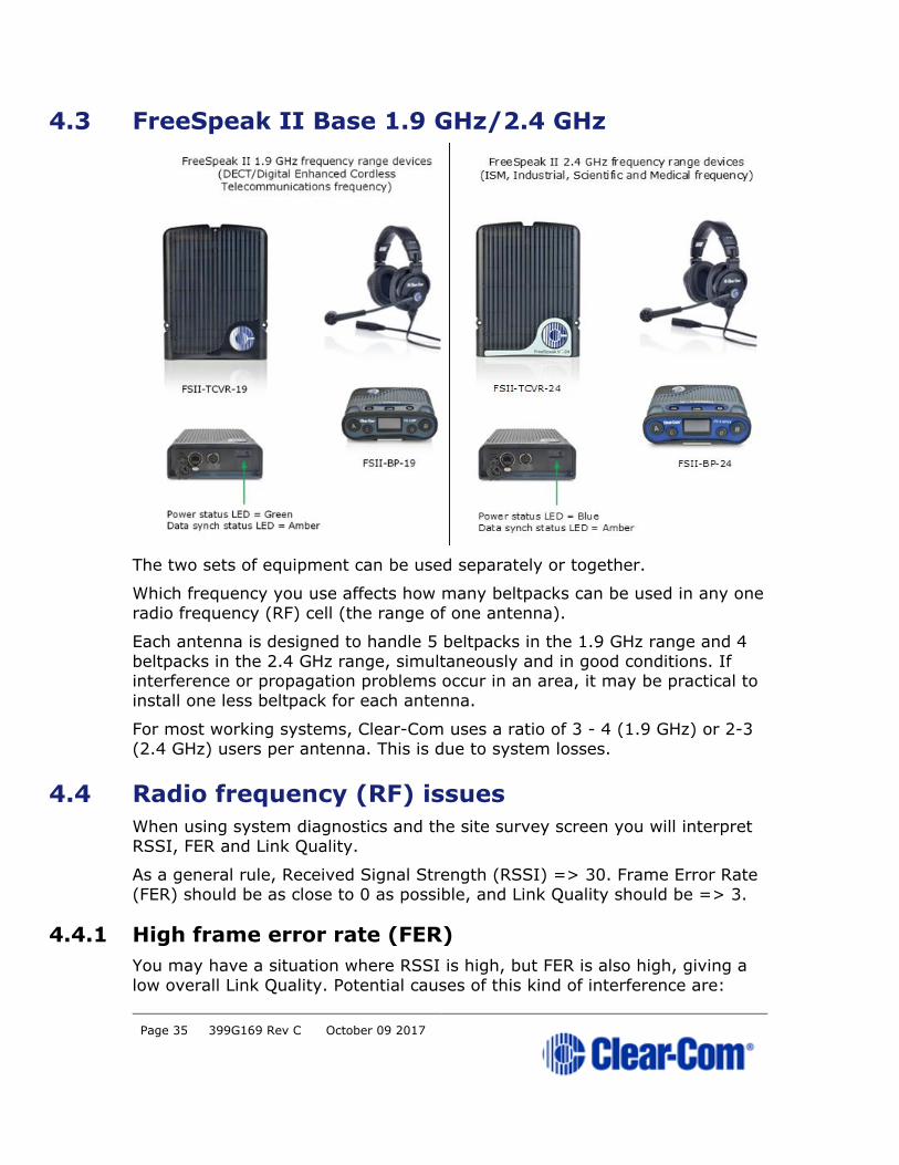
4.3 FreeSpeak II Base 1.9 GHz/2.4 GHz
The two sets of equipment can be used separately or together.
Which frequency you use affects how many beltpacks can be used in any one
radio frequency (RF) cell (the range of one antenna).
Each antenna is designed to handle 5 beltpacks in the 1.9 GHz range and 4
beltpacks in the 2.4 GHz range, simultaneously and in good conditions. If interference or propagation problems occur in an area, it may be practical to
install one less beltpack for each antenna.
For most working systems, Clear-Com uses a ratio of 3 - 4 (1.9 GHz) or 2-3
(2.4 GHz) users per antenna. This is due to system losses.
4.4 Radio frequency (RF) issues
When using system diagnostics and the site survey screen you will interpret
RSSI, FER and Link Quality.
As a general rule, Received Signal Strength (RSSI) => 30. Frame Error Rate
(FER) should be as close to 0 as possible, and Link Quality should be => 3.
4.4.1 High frame error rate (FER)
You may have a situation where RSSI is high, but FER is also high, giving a
low overall Link Quality. Potential causes of this kind of interference are:

Page 36 399G169 Rev C October 09 2017
• There is another RF device in the area. This can be tested using a
band monitor or spectrum analyser.
• There are reflective surfaces in the area causing Long Delay Spread
Multipath interference. This kind of interference is improved by
careful antenna placing, to avoid signal reflection. You may need
advice from your Clear-Com representative in this situation.
4.4.2 National radio carrier frequencies
The carrier frequencies allocated for a radio space vary according to location.
This affects the amount of beltpacks that can be supported in one RF cell.
Location Number of carrier
frequencies
Maximum beltpacks
in one RF cell
United States 5 25 beltpacks
European Union and
elsewhere
10 50 beltpacks

Page 37 399G169 Rev C October 09 2017
5 Using the FreeSpeak II Splitter (FSII-SPL)
5.1 Introduction
The FreeSpeak II Base antenna splitter is a device that connects up to 5
antennas to a FreeSpeak Base (both FreeSpeak I and FreeSpeak II, 1.9 and 2.4 systems) or an Eclipse matrix. Using the splitter, audio can be routed
from the Base to antennas either via Cat5/6 Ethernet cable (RJ45) or a Fiber
connection.
Using a splitter with Cat5/6 RJ45 connection
Using a splitter with Fiber connection.

Page 38 399G169 Rev C October 09 2017
The antenna connections are switched between RJ45 and Fiber routing using
dip switches set inside the splitter.
Page 39 399G169 Rev C October 09 2017
Note: When using Fiber, you must install Fiber modules.
Note: When using the splitter with third party routing devices, antenna
synchronisation data is not passed. In this case, you need to set the splitter
to 'local synch' mode.
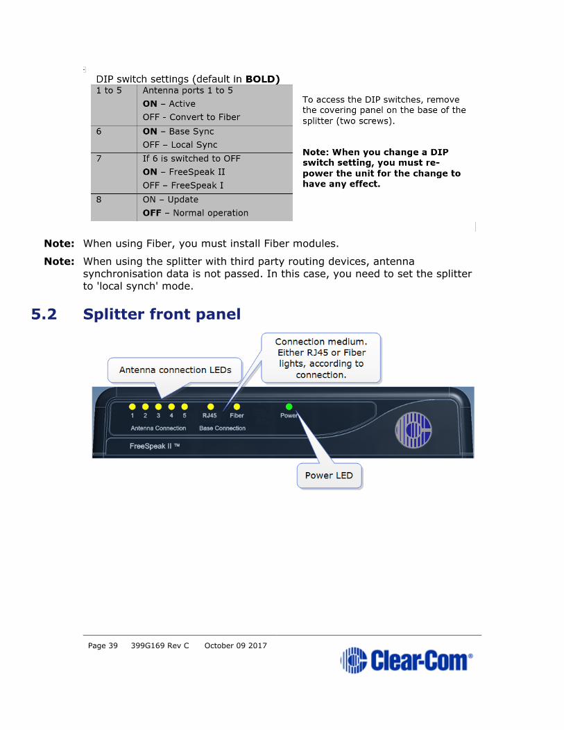
5.2 Splitter front panel

Page 40 399G169 Rev C October 09 2017
5.3 Splitter rear connectors
5.4 Splitter software version
Splitter software is not usually user upgradable, but if necessary you can find
out the splitter software version (usually for system diagnostic purposes) by connecting to the splitter with a PC and using a serial console emulator such
as Tera Term.
1) Remove the covering panel (two screws) on the base of the splitter to
access a USB (micro) port next to the dip switch settings.
2) Connect the splitter to a PC using a USB A to micro B cable.
3) Allow windows to install a USB com port driver (this should be
automatic).
4) Using a serial console emulator (such as Tera Term), input serial
console settings.

Page 41 399G169 Rev C October 09 2017
5) Open the serial console. Press the space bar and the splitter will
output its software version as shown.

Page 42 399G169 Rev C October 09 2017
6 Using Beltpacks
Beltpacks are always configured using Roles. For more information, see 8
Roles.
6.1 Registering Beltpacks
Wireless beltpacks must be registered to your Base Station before you can
use them with the antennas.
Roles must be available for beltpacks before you register them. Your system
arrives with default Roles which can be used, or you can create your own.
There are two ways of registering beltpacks:
• Registering beltpacks using USB cable
• Register beltpacks over-the-air (OTA).
Registering by USB cable is the quickest and easiest way.
6.1.1 Registering beltpacks using USB cable
You must have a USB A to micro USB B cable and the beltpacks to hand
before you start.
1) Connect a beltpack to the Base Station using a USB A to micro USB B
cable.
The beltpack can be powered on either before or after connection.
The Base Station will show 'Beltpack is now registered' in the front menu
screens.
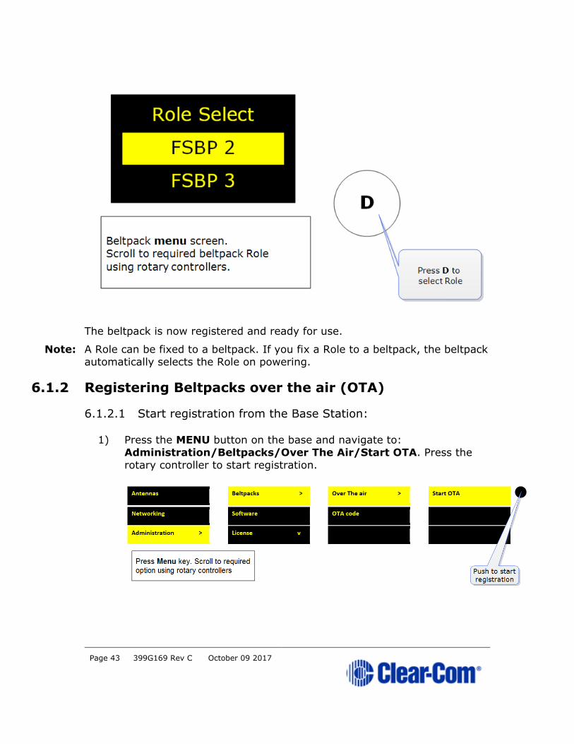
2) Select an available Role from the beltpack screen.
Page 43 399G169 Rev C October 09 2017
The beltpack is now registered and ready for use.
Note: A Role can be fixed to a beltpack. If you fix a Role to a beltpack, the beltpack
automatically selects the Role on powering.
6.1.2 Registering Beltpacks over the air (OTA)
6.1.2.1 Start registration from the Base Station:
1) Press the MENU button on the base and navigate to:
Administration/Beltpacks/Over The Air/Start OTA. Press the
rotary controller to start registration.
Page 44 399G169 Rev C October 09 2017
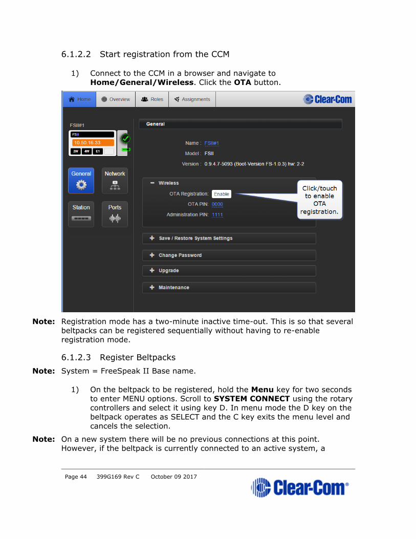
6.1.2.2 Start registration from the CCM
1) Connect to the CCM in a browser and navigate to
Home/General/Wireless. Click the OTA button.
Note: Registration mode has a two-minute inactive time-out. This is so that several beltpacks can be registered sequentially without having to re-enable
registration mode.
6.1.2.3 Register Beltpacks
Note: System = FreeSpeak II Base name.
1) On the beltpack to be registered, hold the Menu key for two seconds
to enter MENU options. Scroll to SYSTEM CONNECT using the rotary
controllers and select it using key D. In menu mode the D key on the
beltpack operates as SELECT and the C key exits the menu level and
cancels the selection.
Note: On a new system there will be no previous connections at this point.
However, if the beltpack is currently connected to an active system, a

Page 45 399G169 Rev C October 09 2017
confirmation screen will appear. Select Yes to connect to a new system or No
to remain connected to the current system.
Available systems and previously registered systems will be visible on the
beltpack menu screen.
To connect the beltpack to the system, the system must be visible (V) and in
registration (pairing) mode. If the system is not in registration mode (P
visible), registration should be re-started (Step 1).
Connect the beltpack to the system using key D.
6.1.2.4 Enter pairing code
Enter the four-digit pairing code for the system using both rotary controllers
and the menu select key (D). The default code is 0000.
Note: The O.T.A. pin code is available from the Base Station menus and the CCM.
See Administration/Beltpacks on the Base Station,
Home/General/Wireless in the CCM.
Page 46 399G169 Rev C October 09 2017
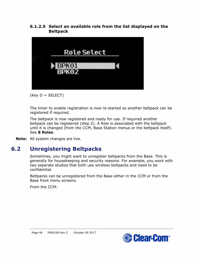
6.1.2.5 Select an available role from the list displayed on the
Beltpack
(Key D = SELECT)
The timer to enable registration is now re-started so another beltpack can be
registered if required.
The beltpack is now registered and ready for use. If required another
beltpack can be registered (step 2). A Role is associated with the beltpack
until it is changed (from the CCM, Base Station menus or the beltpack itself).
See 8 Roles.
Note: All system changes are live.
6.2 Unregistering Beltpacks
Sometimes, you might want to unregister beltpacks from the Base. This is generally for housekeeping and security reasons. For example, you work with
two separate studios that both use wireless beltpacks and need to be
confidential.
Beltpacks can be unregistered from the Base either in the CCM or from the
Base front menu screens.
From the CCM:

Page 47 399G169 Rev C October 09 2017
From the Base Station:
6.3 Assign channels to Beltpack keys
Audio assignment for beltpacks is always done with a Role. A Role is a pre-
defined beltpack configuration map. You select a Role for a beltpack when it
is first powered on. The Role a beltpack is using can be changed from the
Base station, the CCM or the beltpack itself.
In the first case, it is easiest to use the default Role. This puts Channel 1 and
Channel 2 on to the beltpack keys.

Page 48 399G169 Rev C October 09 2017
To change the Channel on a beltpack you need to edit the Role that beltpack
is using. Find the beltpack Role name at the bottom of the beltpack screen:
Edit beltpack Role in the CCM.

Page 49 399G169 Rev C October 09 2017
Edit beltpack Role from the Base Station menu screens.
Note: You can assign audio to keys C, D and Reply. To return the status of these keys to Call and Reply, you must deselect or unassign the audio assignment.
Page 50 399G169 Rev C October 09 2017
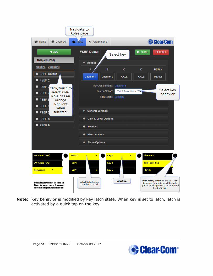
A selected assignment turns blue in the CCM. Click on a blue assignment
again to deselect it. From the Base Station menu screens go to Key
Assign/Role/Key/Unassigned.
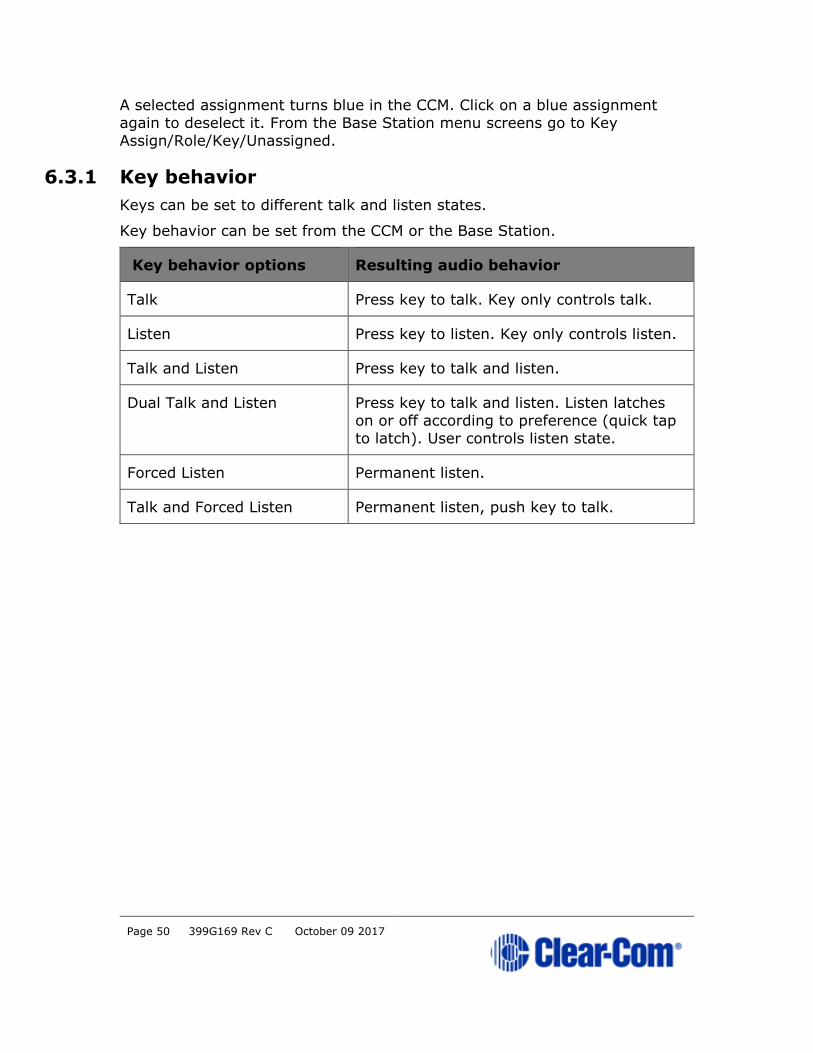
6.3.1 Key behavior
Keys can be set to different talk and listen states.
Key behavior can be set from the CCM or the Base Station.
Key behavior options Resulting audio behavior
Talk Press key to talk. Key only controls talk.
Listen Press key to listen. Key only controls listen.
Talk and Listen Press key to talk and listen.
Dual Talk and Listen Press key to talk and listen. Listen latches
on or off according to preference (quick tap
to latch). User controls listen state.
Forced Listen Permanent listen.
Talk and Forced Listen Permanent listen, push key to talk.
Page 51 399G169 Rev C October 09 2017
Note: Key behavior is modified by key latch state. When key is set to latch, latch is
activated by a quick tap on the key.
Page 52 399G169 Rev C October 09 2017
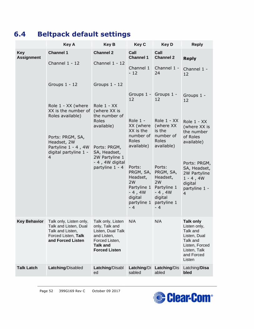
6.4 Beltpack default settings
Key A Key B Key C Key D Reply
Key Assignment
Channel 1
Channel 1 - 12
Groups 1 - 12
Role 1 - XX (where XX is the number of
Roles available)
Ports: PRGM, SA, Headset, 2W
Partyline 1 - 4 , 4W digital partyline 1 -
4
Channel 2
Channel 1 - 12
Groups 1 - 12
Role 1 - XX (where XX is
the number of Roles
available)
Ports: PRGM, SA, Headset,
2W Partyline 1 - 4 , 4W digital
partyline 1 - 4
Call Channel 1
Channel 1
- 12
Groups 1 -
12
Role 1 - XX (where
XX is the number of
Roles
available)
Ports:
PRGM, SA, Headset,
2W Partyline 1
- 4 , 4W digital
partyline 1
- 4
Call Channel 2
Channel 1 -
24
Groups 1 -
12
Role 1 - XX (where XX
is the number of
Roles
available)
Ports:
PRGM, SA, Headset,
2W Partyline 1
- 4 , 4W digital
partyline 1
- 4
Reply
Channel 1 -
12
Groups 1 -
12
Role 1 - XX
(where XX is the number
of Roles
available)
Ports: PRGM,
SA, Headset, 2W Partyline
1 - 4 , 4W digital
partyline 1 -
4
Key Behavior Talk only, Listen only, Talk and Listen, Dual Talk and Listen, Forced Listen, Talk and Forced Listen
Talk only, Listen only, Talk and Listen, Dual Talk and Listen, Forced Listen, Talk and Forced Listen
N/A N/A Talk only Listen only, Talk and Listen, Dual Talk and Listen, Forced Listen, Talk and Forced Listen
Talk Latch Latching/Disabled Latching/Disabled
Latching/Disabled
Latching/Disabled
Latching/Disabled

Page 53 399G169 Rev C October 09 2017
General settings
Description Enter description for Role (optional)
Display brightness Very low - Very high
Dimmed tallies Enabled/Disabled
Latch Disabled Enabled/Disabled
Reply Auto-Clear 1 - 60 secs (10 sec)
Display Dim timeout 5 - 120 secs (30 sec)
Display Off timeout 5 - 120 secs (30 sec)
Listen Again timeout Off, 1 -240 mins (240 mins)
Listen Again record Off, 1 - 15 secs (15 secs)
Gain and level options
Input Gain 15 dB to -70 dB (0 dB)
Output Gain 15 dB to -70 dB (0 dB)
Line-In Volume 6 dB to -15 dB (0 dB)
Master Volume -o.4 dB to -69.9 dB (0 dB)
Min Master Volume Off, -24.9 dB, -11.0 dB, - 6.0 dB
Headset
Headset Limit 8 dB to -12 dB (0 dB)
Sidetone Level 0 dB to -24.9 dB (0 dB)
Mic Echo Cancellation Disabled/Enabled
Menu access
Menu Access Level Advanced/Normal/Basic/None
Display Mode Intercom Mode/Partyline Mode
Master Volume Mode Talk Keys/Master Volume
Alarm options
Battery Alarm Mode Vibrate and Audible/Vibrate Only/Audible Only/Off
Low Battery Threshold 0% to 100% (10%)

Page 54 399G169 Rev C October 09 2017
Call Alert Mode Vibrate and Audible/Vibrate
Only/Audible Only/Off
Out Of Range Alarm Audio Only/Off
Page 55 399G169 Rev C October 09 2017
7 Beltpack features
7.1 Menu key operation
The menu button on beltpacks has several functions.
• A two second press allows the user to enter menu mode.
• A quick tap on the button can be configured in two different ways by
setting 'menu key operation' in Roles. This quick tap functionality is
called 'Menu Key Operation'.
Menu Key Operation has two settings:
• Trigger Listen Again (replays the last call to the beltpack). This is
the default setting.
• Switch volume control (A and B, C and D).
Toggle beltpack rotary volume controls between A and B, C and D
This feature allows the user to toggle rotary volume control between keys A
and B, and C and D using a quick tap of the menu button. This is helpful if
you have different audio sources assigned to each key.
This mode has a 5 second inactive time-out, after which time to rotary controllers will revert to controlling volume on keys A and B. To re-activate
this mode in order to adjust C and D, use another quick tap of the menu key.
To switch quickly between A and B, and C and D, tap the menu key to toggle.
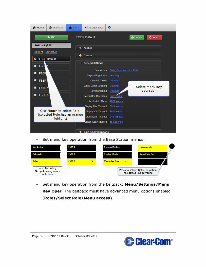
7.1.1 Set menu key operation
This feature can be set under Roles in the CCM, from the Base Station front
menus and from the beltpack itself (advanced menu options).
• Set menu key operation in the CCM.
Page 56 399G169 Rev C October 09 2017
• Set menu key operation from the Base Station menus:
• Set menu key operation from the beltpack: Menu/Settings/Menu
Key Oper. The beltpack must have advanced menu options enabled
(Roles/Select Role/Menu access).

Page 57 399G169 Rev C October 09 2017
7.2 Master volume low level limiter (beltpacks)
7.2.1 About beltpack low level limit
This feature sets a low level limit in order to prevent beltpacks from being
turned down so low they cannot be heard.
How this feature is used depends on your preferred working practice: it is
possible to turn the volume on the beltpack down so low that all audio is
inaudible. This can cause confusion among the unwary, although some users
may want to turn the volume down completely on occasion.
Values: -6, -12, -21, -70 OFF. Default value = -70 OFF. If OFF, audio can
be turned down so low it cannot be heard at all.
7.2.2 Setting beltpack low level limit
The low level limiter feature is set in Roles, from the CCM, The Base Station
menus or from the beltpack itself.
• From the CCM
• From the Base Station menus.

Page 58 399G169 Rev C October 09 2017
• Set low level limiter on a beltpack: (Menu/Settings/Headset
Options). The beltpack must have advanced menu options enabled
(Roles/Select Role/Menu access).
7.3 Configurable eavesdropping
7.3.1 About eavesdropping
Releases of FreeSpeak before FreeSpeak II Base left the beltpack mic
permanently open, meaning that audio coming from the beltpack could be
listened to even if the user had no active talk routes. This feature can now be
configured as required for each beltpack/Role in your wireless system.
The default for FreeSpeak II Base and above is Eavesdropping disabled.
However, earlier versions will revert to Eavesdropping enabled, the
headset mic will remain open.
7.3.2 Setting eavesdropping on beltpacks
• Set eavesdropping function in the CCM.

Page 59 399G169 Rev C October 09 2017
• Set eavesdropping function from the Base Station menus:
7.4 AA Battery Type: Alkaline/NiMh
7.4.1 About battery type
FreeSpeak II wireless beltpacks are supplied with Li-ion batteries and battery
charger. However, in some cases you may wish to use AA batteries. Alkaline
batteries can be used as a quick, easily available replacement. NiMH
batteries can be used in environments (for instance, high
atmospheric/hyperbaric) where Li-ion batteries are prohibited.

Page 60 399G169 Rev C October 09 2017
When using AA batteries of either kind, it is helpful to set battery type so
that battery capacity can be monitored accurately. NiMH batteries and alkaline batteries have different discharge patterns and setting this option
will allow for that.
Default AA battery type = Alkaline.
7.4.2 Setting AA battery type
• From the Base Station:
• From the CCM:
7.5 Using the beltpack functions
7.5.1 Volume operation
Volume operation on beltpacks can be set according to user preference.
Control volume operation via the beltpack Role.

Page 61 399G169 Rev C October 09 2017
Volume operation mode
Master volume Rotary controllers adjust volume on
all 5 beltpack keys
Talk keys Left rotary controller adjusts volume
on A and B, right rotary controller
adjusts volume on C and D.
7.5.2 Controlling volume operation on beltpacks
• From the Base Station:
• From the CCM:
Page 62 399G169 Rev C October 09 2017
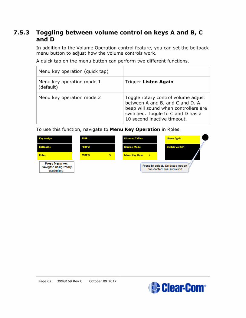
7.5.3 Toggling between volume control on keys A and B, C
and D
In addition to the Volume Operation control feature, you can set the beltpack
menu button to adjust how the volume controls work.
A quick tap on the menu button can perform two different functions.
Menu key operation (quick tap)
Menu key operation mode 1
(default)
Trigger Listen Again
Menu key operation mode 2 Toggle rotary control volume adjust
between A and B, and C and D. A beep will sound when controllers are
switched. Toggle to C and D has a
10 second inactive timeout.
To use this function, navigate to Menu Key Operation in Roles.

Page 63 399G169 Rev C October 09 2017
8 Roles
8.1 About FreeSpeak II Base Roles
Use Roles to program beltpack keys with audio and related settings.
A Role is a pre-configured setting, designed to enable rapid system set-up.
You will always program audio and related settings for each beltpack via it's Role. Your FreeSpeak II Base arrives with default Roles for all your beltpacks
(5 or 25 beltpacks according to product and licence).
In FreeSpeak II Base each beltpack has its own Role, and you must have
enough Roles before you power beltpacks on. Use the pre-defined Roles, edit
the pre-defined Roles, clone existing Roles or create new ones as required.
A Role cannot be used twice in FreeSpeak II Base.
The default Role (which can be edited) uses Channel 1 and 2. Roles also
contain settings such as volume, key latching, menu access, Talk and Listen
behavior (key behavior) and alerts.
Note: While the purpose of Roles is always to enable fast set-up, how Roles work is
influenced by underlying system architecture. This means that they work
slightly different across Clear-Com products. Refer to your system
documentation for guidance.
8.2 Default Role settings
Page 64 399G169 Rev C October 09 2017
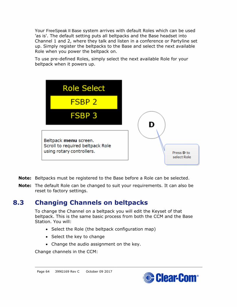
Your FreeSpeak II Base system arrives with default Roles which can be used
'as is'. The default setting puts all beltpacks and the Base headset into
Channel 1 and 2, where they talk and listen in a conference or Partyline set
up. Simply register the beltpacks to the Base and select the next available
Role when you power the beltpack on.
To use pre-defined Roles, simply select the next available Role for your
beltpack when it powers up.
Note: Beltpacks must be registered to the Base before a Role can be selected.
Note: The default Role can be changed to suit your requirements. It can also be
reset to factory settings.
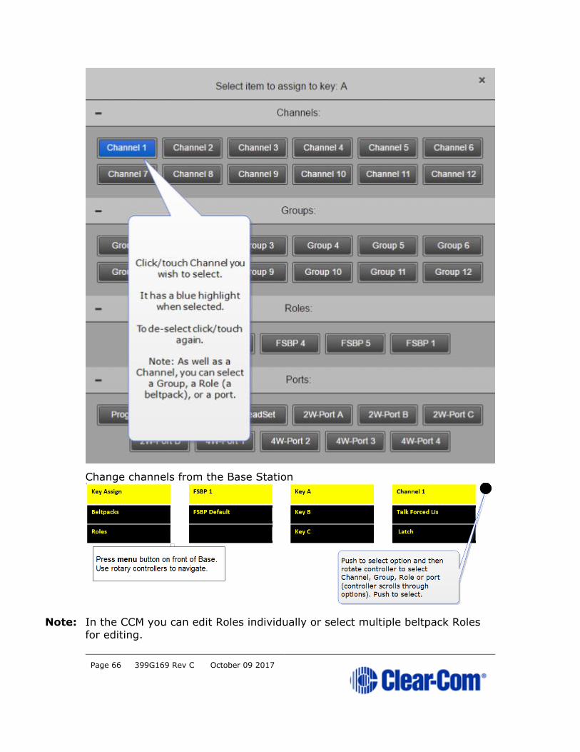
8.3 Changing Channels on beltpacks
To change the Channel on a beltpack you will edit the Keyset of that
beltpack. This is the same basic process from both the CCM and the Base
Station. You will:
• Select the Role (the beltpack configuration map)
• Select the key to change
• Change the audio assignment on the key.
Change channels in the CCM:

Page 65 399G169 Rev C October 09 2017
Page 66 399G169 Rev C October 09 2017
Change channels from the Base Station
Note: In the CCM you can edit Roles individually or select multiple beltpack Roles
for editing.

Page 67 399G169 Rev C October 09 2017
8.4 Change beltpack settings
You can change any of the available settings either in the online
configuration manager (CCM) or from the Base menu screens (navigate to
Roles in the first menu screen). Each page in the CCM has context sensitive
help: press ? in the navigation bar.
Note: In the CCM you can edit Roles individually or select multiple beltpack Roles
for editing.
Changes you make from the CCM or the Base Station front menu screens are
live.
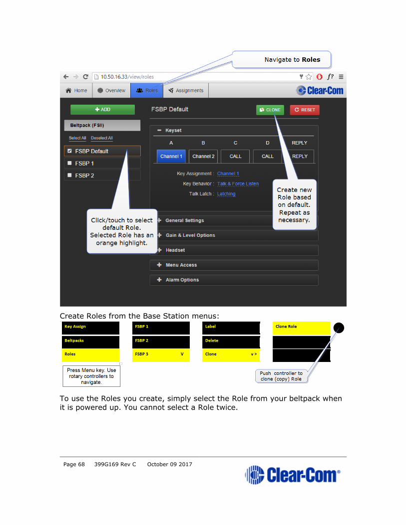
8.5 How to create Roles for beltpacks
You can work with the default Roles, or create new ones. Roles can be
deleted.
Create Roles in the CCM.
Page 68 399G169 Rev C October 09 2017
Create Roles from the Base Station menus:
To use the Roles you create, simply select the Role from your beltpack when
it is powered up. You cannot select a Role twice.
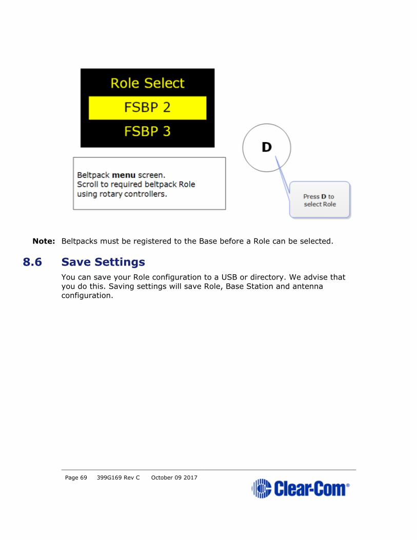
Page 69 399G169 Rev C October 09 2017
Note: Beltpacks must be registered to the Base before a Role can be selected.
8.6 Save Settings
You can save your Role configuration to a USB or directory. We advise that
you do this. Saving settings will save Role, Base Station and antenna
configuration.
Page 70 399G169 Rev C October 09 2017
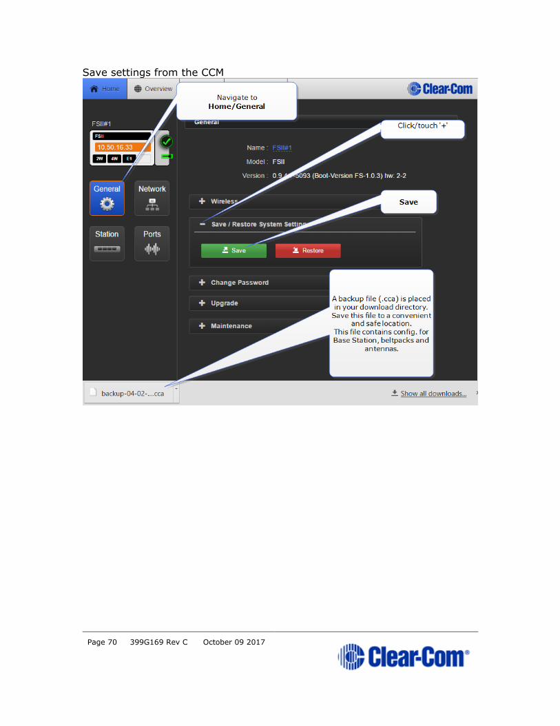
Save settings from the CCM
Page 71 399G169 Rev C October 09 2017
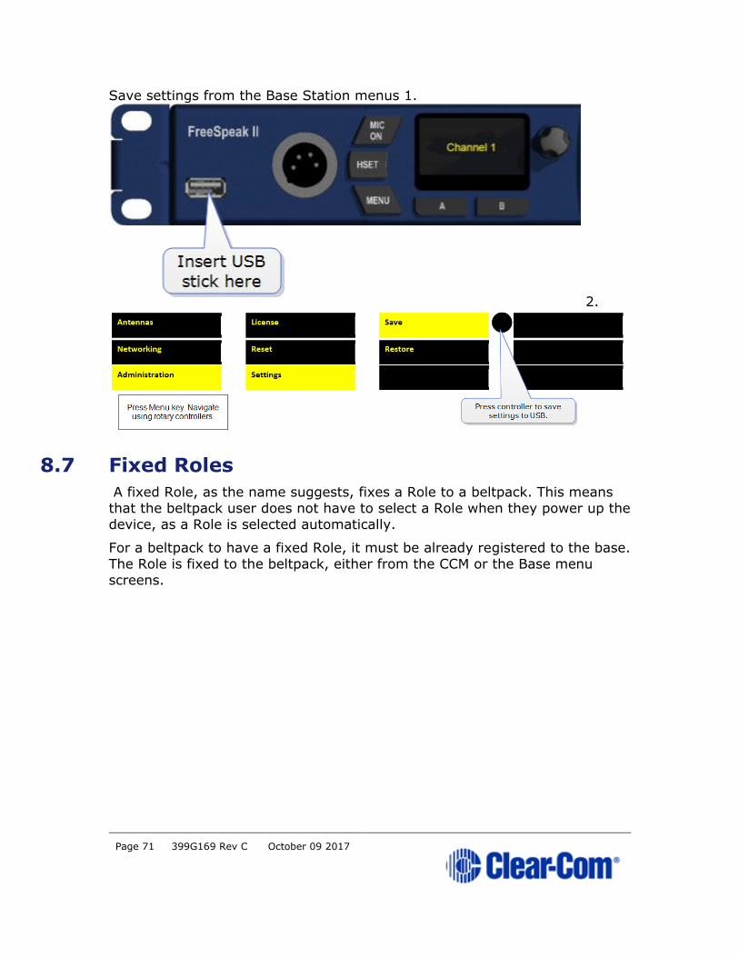
Save settings from the Base Station menus 1.
2.
8.7 Fixed Roles
A fixed Role, as the name suggests, fixes a Role to a beltpack. This means
that the beltpack user does not have to select a Role when they power up the
device, as a Role is selected automatically.
For a beltpack to have a fixed Role, it must be already registered to the base.
The Role is fixed to the beltpack, either from the CCM or the Base menu
screens.

Page 72 399G169 Rev C October 09 2017
Fix a Role in the CCM:

Page 73 399G169 Rev C October 09 2017
Fix a Role from the Base menu screens:

Page 74 399G169 Rev C October 09 2017
9 Core Configuration Manager (CCM)
The Core Configuration Manager is a quick and convenient way to configure
your FreeSpeak II system.
9.1 How to access the CCM
1) Make sure the Base Station is connected to a network (either LAN
connector on back of device).
2) Open a browser (PC, tablet, mobile) and input the IP address of your
Base Station in the URL field. Find the IP address in the front menu
screens of your device: Menu/Networking/Preferences/IP
address.
Page 75 399G169 Rev C October 09 2017
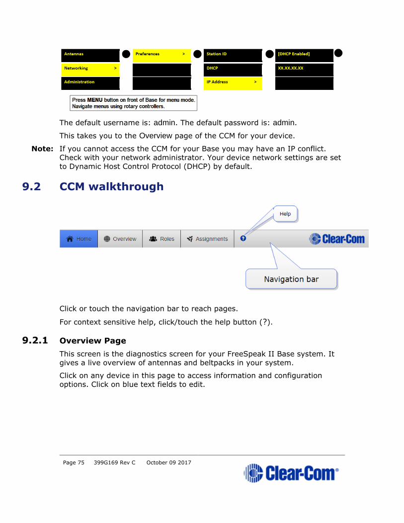
The default username is: admin. The default password is: admin.
This takes you to the Overview page of the CCM for your device.
Note: If you cannot access the CCM for your Base you may have an IP conflict.
Check with your network administrator. Your device network settings are set
to Dynamic Host Control Protocol (DHCP) by default.
9.2 CCM walkthrough
Click or touch the navigation bar to reach pages.
For context sensitive help, click/touch the help button (?).
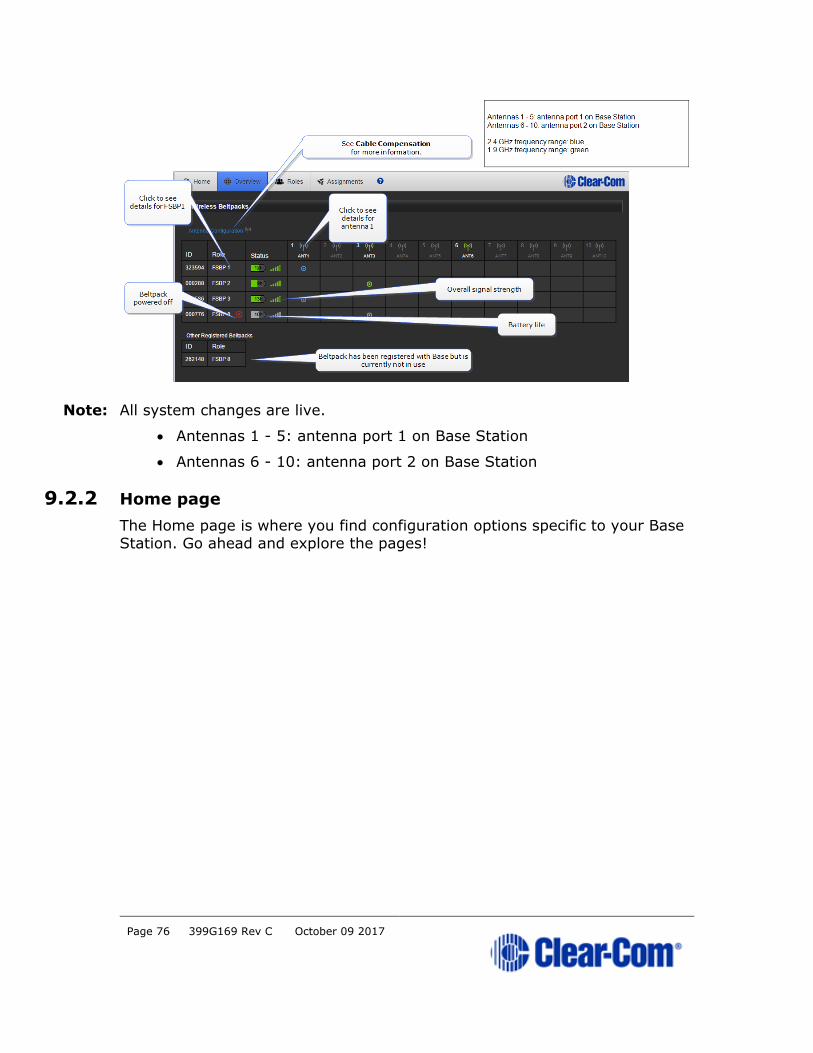
9.2.1 Overview Page
This screen is the diagnostics screen for your FreeSpeak II Base system. It
gives a live overview of antennas and beltpacks in your system.
Click on any device in this page to access information and configuration
options. Click on blue text fields to edit.
Page 76 399G169 Rev C October 09 2017
Note: All system changes are live.
• Antennas 1 - 5: antenna port 1 on Base Station
• Antennas 6 - 10: antenna port 2 on Base Station
9.2.2 Home page
The Home page is where you find configuration options specific to your Base
Station. Go ahead and explore the pages!

Page 77 399G169 Rev C October 09 2017
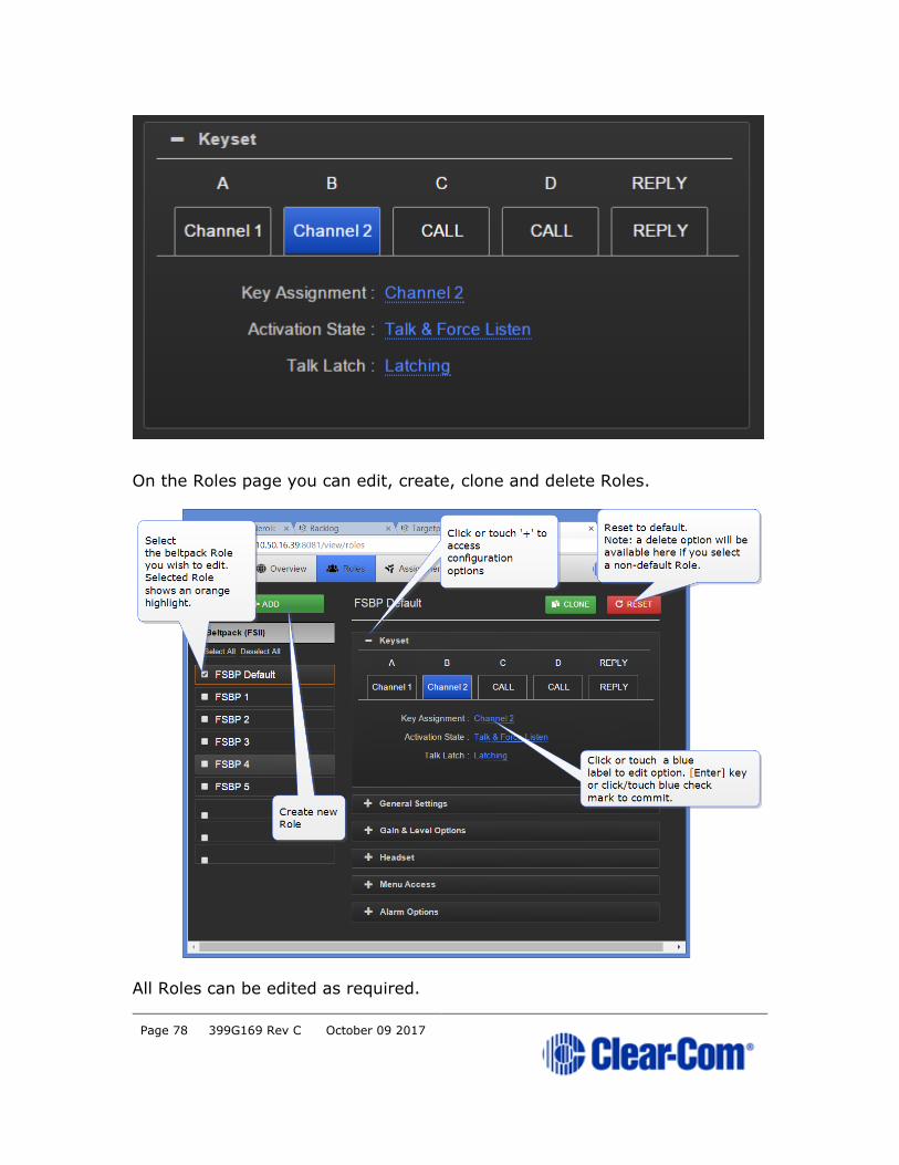
9.2.3 Roles Page
The Roles page is where you assign audio to beltpacks and configure
beltpack settings.
Roles are pre-configurations; default audio routes and settings that are applied to your device when it is first powered up (a Role is selected by the
beltpack user). The default Role can be edited and/or reset to default.
Individual Roles can be edited, deleted, cloned and created.
In FreeSpeak II Base a Role is attached to a specific beltpack in a one-to-one
relationship. The default Role puts Channel 1 and 2 on beltpack keys A and B, with C and D set as call keys. The Reply key can be re-assigned to a
Channel as required.
Below is the Beltpack default configuration.
Page 78 399G169 Rev C October 09 2017
On the Roles page you can edit, create, clone and delete Roles.
All Roles can be edited as required.
Page 79 399G169 Rev C October 09 2017
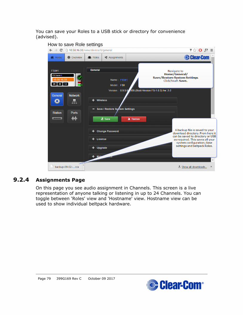
You can save your Roles to a USB stick or directory for convenience
(advised).
How to save Role settings
9.2.4 Assignments Page
On this page you see audio assignment in Channels. This screen is a live
representation of anyone talking or listening in up to 24 Channels. You can
toggle between 'Roles' view and 'Hostname' view. Hostname view can be
used to show individual beltpack hardware.

Page 80 399G169 Rev C October 09 2017
Page 81 399G169 Rev C October 09 2017
10 Configuring audio routes
10.1 About audio routes
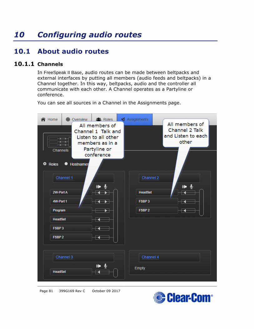
10.1.1 Channels
In FreeSpeak II Base, audio routes can be made between beltpacks and
external interfaces by putting all members (audio feeds and beltpacks) in a
Channel together. In this way, beltpacks, audio and the controller all
communicate with each other. A Channel operates as a Partyline or
conference.
You can see all sources in a Channel in the Assignments page.
Page 82 399G169 Rev C October 09 2017
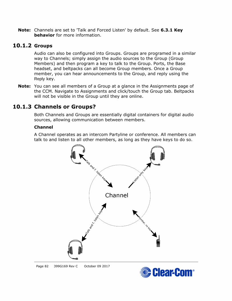
Note: Channels are set to 'Talk and Forced Listen' by default. See 6.3.1 Key
behavior for more information.
10.1.2 Groups
Audio can also be configured into Groups. Groups are programed in a similar
way to Channels; simply assign the audio sources to the Group (Group
Members) and then program a key to talk to the Group. Ports, the Base headset, and beltpacks can all become Group members. Once a Group
member, you can hear announcements to the Group, and reply using the Reply key.
Note: You can see all members of a Group at a glance in the Assignments page of
the CCM. Navigate to Assignments and click/touch the Group tab. Beltpacks
will not be visible in the Group until they are online.
10.1.3 Channels or Groups?
Both Channels and Groups are essentially digital containers for digital audio
sources, allowing communication between members.
Channel
A Channel operates as an intercom Partyline or conference. All members can
talk to and listen to all other members, as long as they have keys to do so.
Page 83 399G169 Rev C October 09 2017
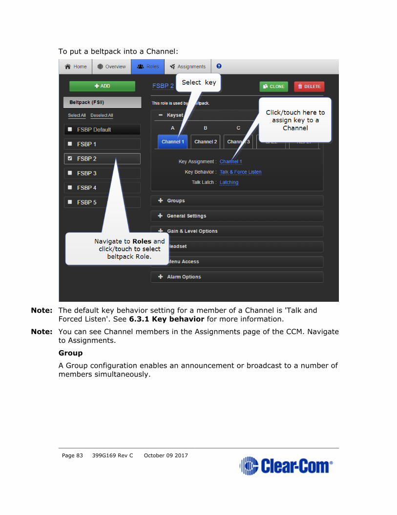
To put a beltpack into a Channel:
Note: The default key behavior setting for a member of a Channel is 'Talk and
Forced Listen'. See 6.3.1 Key behavior for more information.
Note: You can see Channel members in the Assignments page of the CCM. Navigate
to Assignments.
Group
A Group configuration enables an announcement or broadcast to a number of
members simultaneously.
Page 84 399G169 Rev C October 09 2017
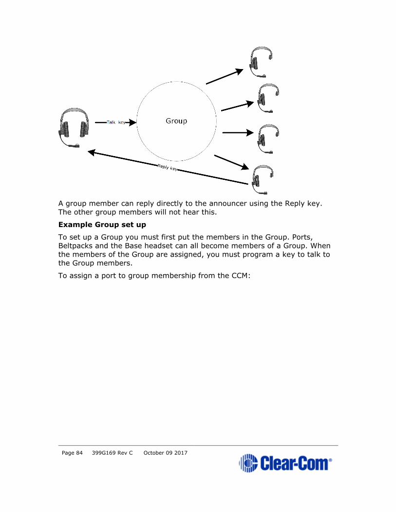
A group member can reply directly to the announcer using the Reply key.
The other group members will not hear this.
Example Group set up
To set up a Group you must first put the members in the Group. Ports,
Beltpacks and the Base headset can all become members of a Group. When
the members of the Group are assigned, you must program a key to talk to
the Group members.
To assign a port to group membership from the CCM:

Page 85 399G169 Rev C October 09 2017
How to program a Talk key to the Group.
Page 86 399G169 Rev C October 09 2017
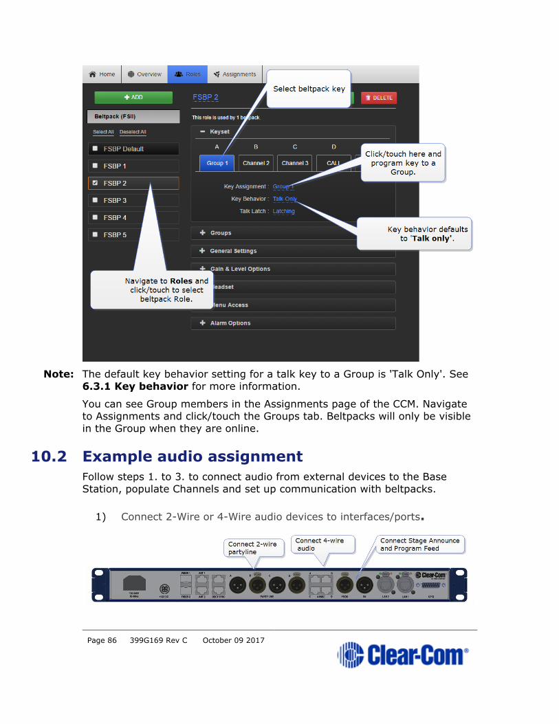
Note: The default key behavior setting for a talk key to a Group is 'Talk Only'. See
6.3.1 Key behavior for more information.
You can see Group members in the Assignments page of the CCM. Navigate
to Assignments and click/touch the Groups tab. Beltpacks will only be visible
in the Group when they are online.
10.2 Example audio assignment
Follow steps 1. to 3. to connect audio from external devices to the Base
Station, populate Channels and set up communication with beltpacks.
1) Connect 2-Wire or 4-Wire audio devices to interfaces/ports.
Page 87 399G169 Rev C October 09 2017
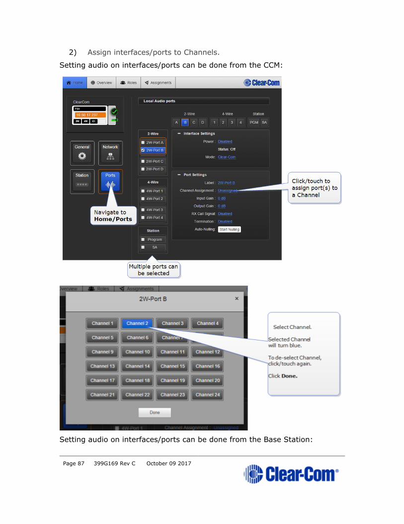
2) Assign interfaces/ports to Channels.
Setting audio on interfaces/ports can be done from the CCM:
Setting audio on interfaces/ports can be done from the Base Station:
Page 88 399G169 Rev C October 09 2017
Note: Configure port settings (power, termination, port function, port levels etc.) as
required.
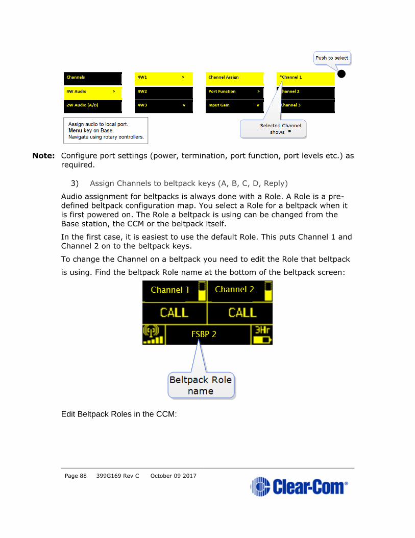
3) Assign Channels to beltpack keys (A, B, C, D, Reply)
Audio assignment for beltpacks is always done with a Role. A Role is a pre-defined beltpack configuration map. You select a Role for a beltpack when it
is first powered on. The Role a beltpack is using can be changed from the
Base station, the CCM or the beltpack itself.
In the first case, it is easiest to use the default Role. This puts Channel 1 and
Channel 2 on to the beltpack keys.
To change the Channel on a beltpack you need to edit the Role that beltpack
is using. Find the beltpack Role name at the bottom of the beltpack screen:
Edit Beltpack Roles in the CCM:
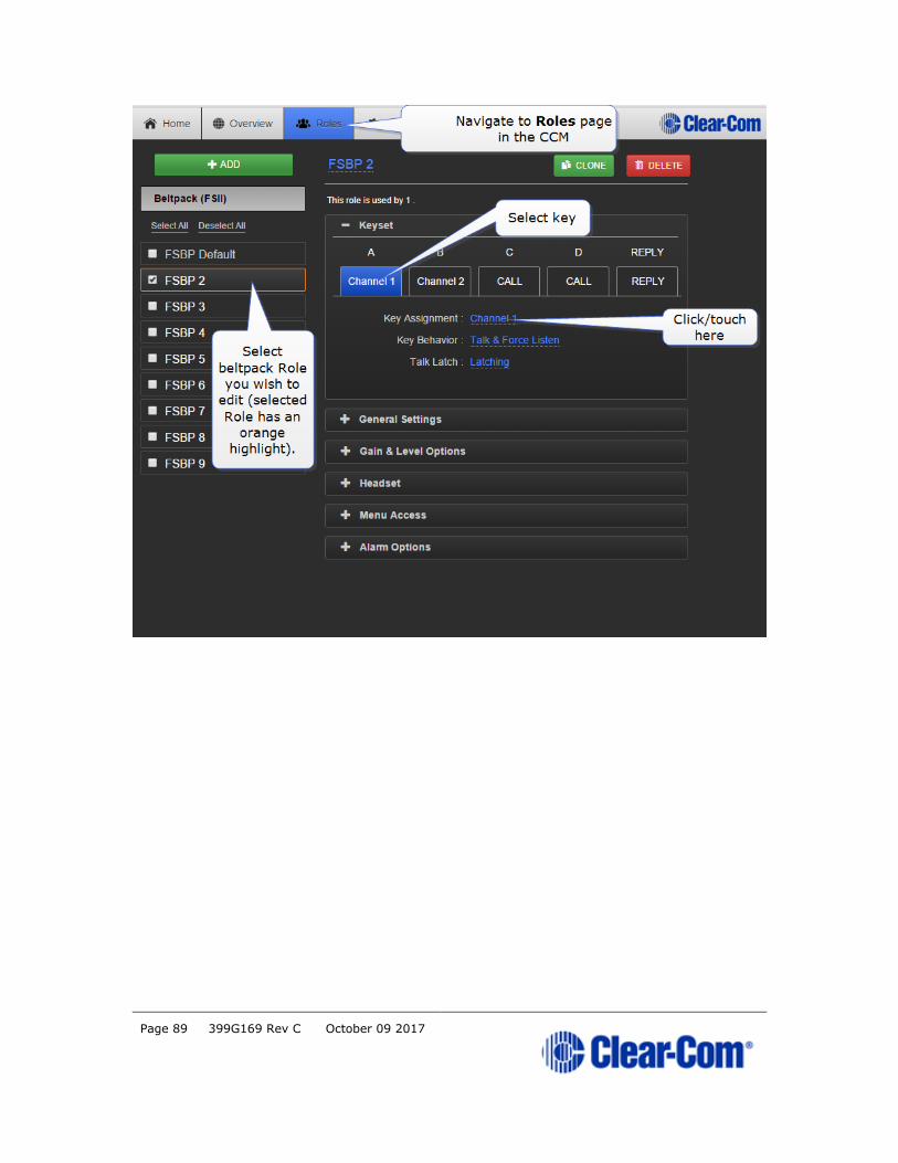
Page 89 399G169 Rev C October 09 2017
Page 90 399G169 Rev C October 09 2017
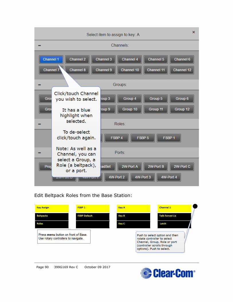
Edit Beltpack Roles from the Base Station:

Page 91 399G169 Rev C October 09 2017
Note: You can assign audio to keys C, D and Reply. To return the status of these
keys to Call and Reply, you must deselect or unassign the audio assignment. A selected assignment turns blue in the CCM. Click on a blue assignment
again to deselect it. From the Base Station menu screens go to Key
Assign/Role/Key/Unassigned.
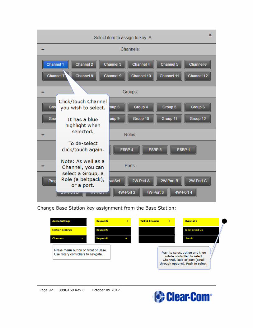
10.3 Change key assignments on the Base Station
10.3.1 Change Channel settings on the Base Station.
The Base Station default setting has Channels 1 - 3 on the first three
Keysets. The 4th Keyset is a Reply key.
This can be edited.
Change Base Station key assignment from the CCM:
Page 92 399G169 Rev C October 09 2017
Change Base Station key assignment from the Base Station:

Page 93 399G169 Rev C October 09 2017
10.4 Configure a one-to-one connection
As well as into Channels, audio can be configured in a point-to-point
relationship (for instance, one beltpack to another in a private
communication).
10.4.1 Example point-to-point audio assignment
When selecting an audio source for any key, (in this example key C on a
beltpack), instead of selecting a Channel, select a beltpack Role or port.
This creates a point-to-point connection. A similar effect could be achieved
by putting two beltpacks into a Channel of their own.
Page 94 399G169 Rev C October 09 2017
11 Connecting different systems
11.1 Interconnection
FreeSpeak II Base can be connected to a range of intercom systems.
• Clear-Com Encore and RTS (2-wire cabled partyline systems)
• DX210 (2-wire/4-wire systems)
• Eclipse (digital matrix systems)
• HelixNet (digital partyline)
• Two-way radio systems
• FreeSpeak II Base can be connected to another FreeSpeak II Base
station in order to share Channels between two Bases, increasing the
range of your system.
11.2 Connecting FreeSpeak II Base to other intercom devices
When connecting FreeSpeak II Base to other intercom devices, the general
process is the same, though there are details that change according to device
type. As a general guideline you need to:
1) Configure the relevant interface (port) settings (see below).
2) Connect the device with CAT5 or microphone cable.
3) Adjust audio levels as required.
11.3 Connecting 2-wire equipment
When connecting 2-wire equipment the following functions should be taken
into consideration:
• Auto-null. Note Every time equipment is changed on a 2-wire
interface (port) you should run auto-null.
• Enable/disable the partyline power. Do this in Ports/2-Wire. Default
setting: Disabled.
• Enable/disable Line termination. Note The line should only be
terminated once on interconnected devices, do not terminate on
more than one piece of equipment. Default setting: Disabled.
Page 95 399G169 Rev C October 09 2017
These functions can be set either in the 2-wire port settings page of the Core
Configuration Manager (CCM) or from the front panel screens on the Base
Station.
11.4 Connecting to 4-wire equipment
When connecting to 4-wire equipment the following need to be taken into
account:
• To minimise noise, use screened (shielded) cable when connecting 4-
wire ports.
• Pin-out configuration (mode) can be set on all FreeSpeak II Base 4-
wire interfaces. This is a software switch that switches the
configuration of the pins on the RJ45 etherCON connectors, according
to the device you are connecting to. Default setting: To Matrix.
11.5 Port function (to matrix or to panel)
Check this function whenever you are connecting 4-wire devices.
11.5.1 About port function
Clear-Com products are designed so matrices can connect directly to
panels/Base Station/main station using a straight-through CAT 5/6
(Ethernet) cable. The pin assignments (inputs and outputs) on these devices are complementary. Previously, a crossover cable was necessary when
connecting Bases to other Bases. It is no longer necessary to use a crossover
cable as there is now a Port Function toggle which changes pinouts as
required. This is function is found in port options and can be set from the
CCM or the Base Station front panel menus.
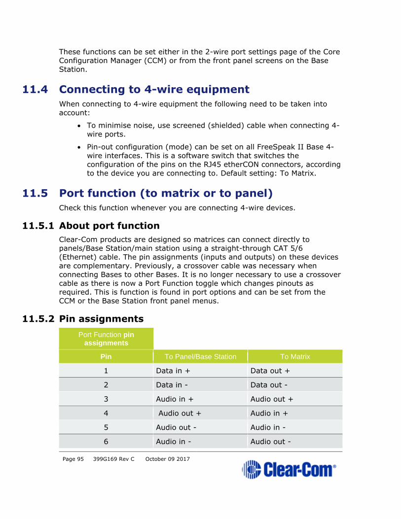
11.5.2 Pin assignments
Port Function pin assignments
Pin To Panel/Base Station To Matrix
1 Data in + Data out +
2 Data in - Data out -
3 Audio in + Audio out +
4 Audio out + Audio in +
5 Audio out - Audio in -
6 Audio in - Audio out -
Page 96 399G169 Rev C October 09 2017
Port Function pin assignments
Pin To Panel/Base Station To Matrix
7 Data out + Data in +
8 Data out - Data in -
Note: When connecting one FreeSpeak II Base to another FreeSpeak II Base, one
device must be set ‘To Matrix’ and the other ‘To Panel’.
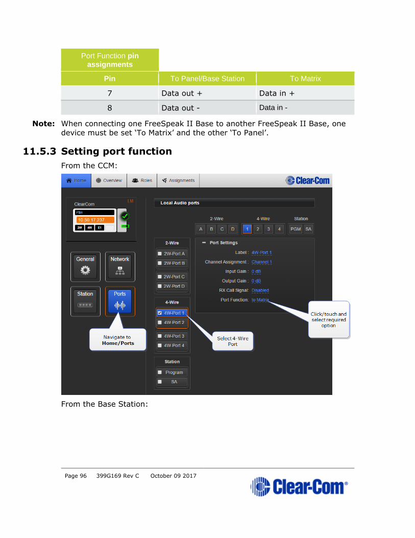
11.5.3 Setting port function
From the CCM:
From the Base Station:

Page 97 399G169 Rev C October 09 2017

Page 98 399G169 Rev C October 09 2017
12 Upgrading devices
12.1 About upgrading devices
To upgrade your devices, you will need to import the upgrade file provided
by Clear-Com into the unit. This can be done either from the browser-based
configuration tool (the CCM) or from the Base Station front menu screens.
The process is the same for each device type.
Device type File type (where xxxx = revision no.)
Base Station FSII_xxxxx.gz
Beltpack PP_xxxxx.FFW
Antenna RFP_xxxx.FFW
12.2 How to upgrade your devices
Upgrade from the CCM:
Upgrade from the Base Station:
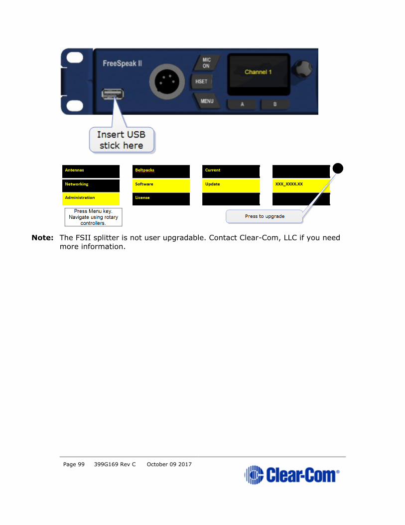
Page 99 399G169 Rev C October 09 2017
Note: The FSII splitter is not user upgradable. Contact Clear-Com, LLC if you need
more information.
Page 100 399G169 Rev C October 09 2017
13 Powering your system
13.1 Powering the FreeSpeak II™ Base
Use two power supplies according to preference:
• Mains power lead (internal power converter)
• DC connector. External wallwart power lead.
Use one power connector or both to guard against one failing.
13.2 Powering wireless beltpacks
Beltpacks are powered by Li-ion battery. Drop-in battery charger supplied.
Battery power status is viewed from:
• Base Station menu screens
• Beltpack menu screens
• Core Configuration Manager (CCM).
For more information, see: Battery Charger Quick Start Guide (PDF available from Clear-Com, LLC website).
Note: You can also power beltpacks using standard AA batteries for convenience. In
situations where Li-ion batteries are prohibited, you can also use nickel metal
hydride batteries (NiMH) but will need to set battery type so battery life
diagnostics are accurate.
13.3 Power 2-wire beltpacks from the Partyline
2-wire Partyline beltpacks can take power from the Partyline:
• FreeSpeak base power: 60 watts supply = 250 mA to Partyline
• ~10 beltpacks per pair of ports, max 20 beltpacks per base.
Note: The Partyline power operates over a pair of ports
To enable power to the Partyline go to Ports, 2-wire in the CCM or in Base
front menu screens.
13.4 Powering the transceiver antennas
• Directly (DC in power connector) or
• From the FreeSpeak II™ Base
Direct power to antenna is recommended. Local (direct) power will increase how far antenna can be positioned from the Base

Page 101 399G169 Rev C October 09 2017
Antenna powered locally:
• Shielded Ethernet cable up to 800 m (2,625 feet) from base or
splitter.
Antenna powered from Base Station (1 antenna only):
• Shielded Ethernet cable, up to 300 m (984 feet) from base.
Note: Using heavier gauge cable will increase available distance.
For more information, see:
• Using the Antenna
• Site survey and RF issues
13.5 Powering the Antenna Splitter
The splitter MUST be powered locally. Power the splitter before you connect
it to the base, or it will take power from the base and this may be
insufficient.
Use the supplied power connector.
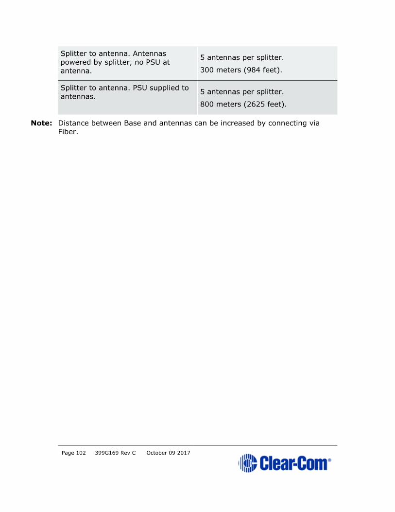
13.6 Recommended powering and cable lengths for a FreeSpeak II Base System
Possible distance from Base Station to antenna
The Base Station can power 1 antenna to a distance of 300 meters (984
feet). More than one antenna and/or greater distances will need direct power
supplied to the antenna.
The figures in this table are based on
the use of 24AWG Cat5/6 cable
Capacity (distance and no. of
devices)
Base to antenna. No PSU at antenna. 1 antenna only.
300 meters (984 feet).
Base to antenna. PSU at antennas. 2 antennas.
800 meters (2625 feet).
Base to splitter. Splitter must have
PSU.
800 meters (2625 feet).
Page 102 399G169 Rev C October 09 2017
Splitter to antenna. Antennas
powered by splitter, no PSU at
antenna.
5 antennas per splitter.
300 meters (984 feet).
Splitter to antenna. PSU supplied to
antennas. 5 antennas per splitter.
800 meters (2625 feet).
Note: Distance between Base and antennas can be increased by connecting via
Fiber.
Page 103 399G169 Rev C October 09 2017
14 Regulatory compliance
Applicant Name: Clear-Com LLC
Applicant Address: 1301 Marina Village Pkwy, Suite 105, Alameda CA 94501,
United States
Manufacturer Name: Clear-Com LLC
Manufacturer Address: 1301 Marina Village Pkwy, Suite 105, Alameda CA
94501, United States
Country of Origin: USA
Brand: Clear-Com
Caution: All products are compliant with regulatory requirements detailed in
this document when the user follows all installation instructions and
operating conditions per Clear-Com specifications
Caution: Use of accessories and peripherals other than those recommended by Clear-Com may void the product's compliance as well as the user's
authority to operate the equipment.
FCC Notice
This device complies with Part 15 of the FCC rules. Operation is subject to
the following two conditions: (1) This device may not cause harmful
interference, and (2) This device must accept any interference received,
including interference that may cause undesired operation.
NOTE: This equipment has been tested and found to comply with the limits
for a Class A digital device, pursuant to Part 15 of the FCC rules. These limits
are designed to provide reasonable protection against harmful interference
when the equipment is operated in a commercial environment. This equipment generates, uses and can radiate radio frequency energy and, if
not installed and used in accordance with the instruction manual, may cause
harmful interference to radio communication. Operation of this equipment in
a residential area is likely to cause harmful interference, in which case the
user will be required to correct the interference at his own expense.
Changes or modifications not expressly approved by Clear-Com, LLC, an HM Electronics, Inc. company could void the user’s authority to operate this
equipment.

Page 104 399G169 Rev C October 09 2017
FCC/IC/EC RF Exposure Warning:
- This product complies with FCC/IC/EC radiation exposure limits set forth for
an uncontrolled environment.
- This product may not be co-located or operated in conjunction with any
other antenna or transmitter.
- The beltpack has been tested to comply with FCC/IC/EC RF Exposure requirements in body-worn position. Use of third party clips or holsters with
the beltpack may not ensure compliance with FCC/IC/EC RF exposure
requirements and should be avoided.
- To comply with FCC/IC/EC RF exposure requirements, the
Antenna/Transceiver unit must be installed and operated at least 20 cm (8
inches) from any person.
Industry Canada Compliance Statement
This Class[A] digital device complies with Canadian ICES-003.
Avis de conformité à la réglementation d'Industrie Canada
Cet appareil est conforme aux CNR d’Industrie Canada applicables aux
appareils radio exempts de licence. L’exploitation est soumise aux deux
conditions suivantes:
(1) cet appareil ne doit pas provoquer d’interféence, et
(2) cet appareil doit accepter toute interféence radioéectrique subie, mêe si
l’interféence est susceptible d’en compromettre le fonctionnement.
Cet éetteur exempt de licence est éuipéd’une antenne intéré. Cet éetteur
exempt de licence n’est pas autoriséàfonctionner avec une autre antenne.
Cet appareil numérique de la class[*] est conforme à la norme NMB-003 du
Canada.
Korean Notice
A급 기기 (업무용 방송통신기자재)
이 기기는 업무용(A급)으로 전자파적합기기로
서 판매자 또는 사용자는 이 점을 주의하시기
바라며, 가정외의 지역에서 사용하는 것을 목
Page 105 399G169 Rev C October 09 2017
적으로 합니다.
KCC 2.4Ghz warning
해당 무선설비는 전파혼신 가능성이 있으므로 인명안전과 관련된 서비스는 할 수
없음
European Union (CE mark)
The CE marking indicates compliance with the following directives and
standards, whenever applicable to the product in question.
Directives:
- Radio Equipment Directive 2014/53/EU
- Electromagnetic Compatibility Directive 2014/30/EU
- Low Voltage Directive 2014/35/EU
- RoHS Directive 2011/65/EU
Standards:
- EN55022/EN55032
- EN55024
- IEC/EN60950-1
- EN300328
- EN301406
- EN301489
- EN50581
Warning:
This is a Class A product. In a domestic environment this product may cause
radio interference in which case the user may be required to take adequate
measures.

Page 106 399G169 Rev C October 09 2017
Waste Electrical and Electronic Equipment (WEEE)
The European Union (EU) WEEE Directive (2012/19/EU) places an obligation
on producers (manufacturers, distributors and/or retailers) to take-back
electronic products at the end of their useful life. The WEEE Directive covers
most Clear-Com products being sold into the EU as of August 13, 2005.
Manufacturers, distributors and retailers are obliged to finance the costs of recovery from municipal collection points, reuse, and recycling of specified
percentages per the WEEE requirements.
Instructions for Disposal of WEEE by Users in the
European Union
The symbol shown below is on the product or on its packaging which
indicates that this product was put on the market after August 13, 2005 and
must not be disposed of with other waste. Instead, it is the user’s
responsibility to dispose of the user’s waste equipment by handing it over to a designated collection point for the recycling of WEEE. The separate
collection and recycling of waste equipment at the time of disposal will help
to conserve natural resources and ensure that it is recycled in a manner that
protects human health and the environment. For more information about
where you can drop off your waste equipment for recycling, please contact
your local authority, your household waste disposal service or the seller from
whom you purchased the product.
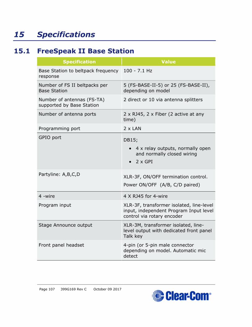
Page 107 399G169 Rev C October 09 2017
15 Specifications
15.1 FreeSpeak II Base Station
Specification Value
Base Station to beltpack frequency
response
100 - 7.1 Hz
Number of FS II beltpacks per
Base Station
5 (FS-BASE-II-5) or 25 (FS-BASE-II),
depending on model
Number of antennas (FS-TA) supported by Base Station
2 direct or 10 via antenna splitters
Number of antenna ports 2 x RJ45, 2 x Fiber (2 active at any time)
Programming port 2 x LAN
GPIO port DB15;
• 4 x relay outputs, normally open
and normally closed wiring
• 2 x GPI
Partyline: A,B,C,D XLR-3F, ON/OFF termination control.
Power ON/OFF (A/B, C/D paired)
4 -wire 4 X RJ45 for 4-wire
Program input XLR-3F, transformer isolated, line-level
input, independent Program Input level
control via rotary encoder
Stage Announce output XLR-3M, transformer isolated, line-
level output with dedicated front panel
Talk key
Front panel headset 4-pin (or 5-pin male connector
depending on model. Automatic mic detect
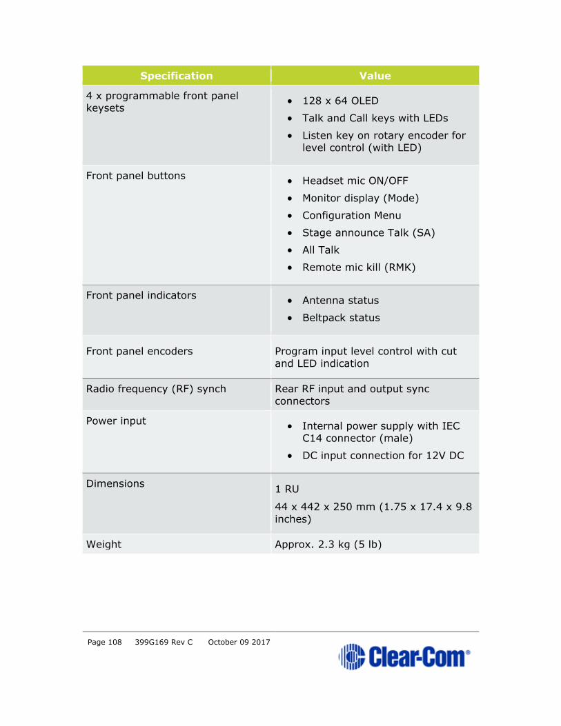
Page 108 399G169 Rev C October 09 2017
Specification Value
4 x programmable front panel keysets
• 128 x 64 OLED
• Talk and Call keys with LEDs
• Listen key on rotary encoder for
level control (with LED)
Front panel buttons • Headset mic ON/OFF
• Monitor display (Mode)
• Configuration Menu
• Stage announce Talk (SA)
• All Talk
• Remote mic kill (RMK)
Front panel indicators • Antenna status
• Beltpack status
Front panel encoders Program input level control with cut
and LED indication
Radio frequency (RF) synch Rear RF input and output sync
connectors
Power input • Internal power supply with IEC
C14 connector (male)
• DC input connection for 12V DC
Dimensions 1 RU
44 x 442 x 250 mm (1.75 x 17.4 x 9.8
inches)
Weight Approx. 2.3 kg (5 lb)
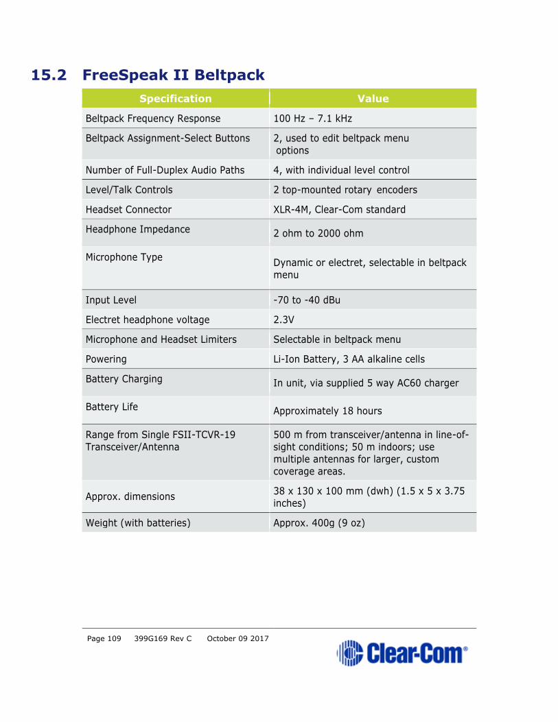
Page 109 399G169 Rev C October 09 2017
15.2 FreeSpeak II Beltpack
Specification Value
Beltpack Frequency Response 100 Hz – 7.1 kHz
Beltpack Assignment-Select Buttons 2, used to edit beltpack menu
options
Number of Full-Duplex Audio Paths 4, with individual level control
Level/Talk Controls 2 top-mounted rotary encoders
Headset Connector XLR-4M, Clear-Com standard
Headphone Impedance 2 ohm to 2000 ohm
Microphone Type Dynamic or electret, selectable in beltpack
menu
Input Level -70 to -40 dBu
Electret headphone voltage 2.3V
Microphone and Headset Limiters Selectable in beltpack menu
Powering Li-Ion Battery, 3 AA alkaline cells
Battery Charging In unit, via supplied 5 way AC60 charger
Battery Life Approximately 18 hours
Range from Single FSII-TCVR-19
Transceiver/Antenna
500 m from transceiver/antenna in line-of-
sight conditions; 50 m indoors; use
multiple antennas for larger, custom
coverage areas.
Approx. dimensions 38 x 130 x 100 mm (dwh) (1.5 x 5 x 3.75
inches)
Weight (with batteries) Approx. 400g (9 oz)

Page 110 399G169 Rev C October 09 2017
15.3 FreeSpeak II Transceiver/Antenna
Specification Value
Beltpacks Supported Per
Transceiver/Antenna
FSII 1.9 GHz devices:5 in one cellular zone
FSII 2.4 GHz devices:4 in one cellular zone
Transceiver Antenna Transmission
Range
Up to 500 m (1475 ft.), line of sight
Maximum Distance, Matrix to
Transceiver via Matrix Port
1,000 m (3,200 ft.) using shielded 24 AWG
cable
500 m (1,600 ft) using shielded 26 AWG cable
Local Powering Via 24VDC power supply
Mounting 3 fixing holes
Dimensions 50 x 140 x 175 mm (dwh)
(2.0 x 5.5 x 6.9 inches)
Weight Approx. 460g (16.1 oz)
15.4 FreeSpeak II Transceiver/Antenna Splitter
Specification Value
Number of Transceiver/Antennas
Supported
10
Number of Splitters Per Base Station 2
Connection Between Base Station
and Splitter
4-pair shielded CAT5 cable with RJ-45
Connection Between Splitter and Transceiver/Antennas
4-pair shielded CAT5 cable with RJ-45
Powering of Splitter Locally powered via external power supply
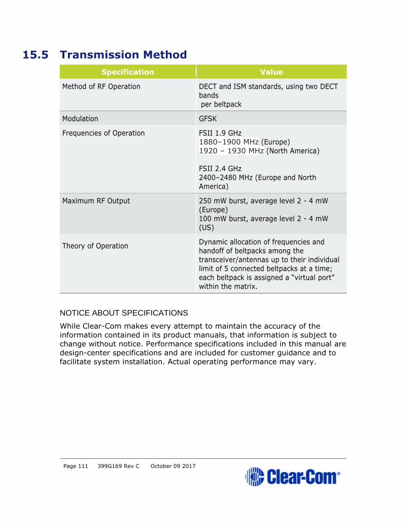
Page 111 399G169 Rev C October 09 2017
15.5 Transmission Method
Specification Value
Method of RF Operation DECT and ISM standards, using two DECT
bands per beltpack
Modulation GFSK
Frequencies of Operation FSII 1.9 GHz
1880–1900 MHz (Europe)
1920 – 1930 MHz (North America)
FSII 2.4 GHz
2400–2480 MHz (Europe and North
America)
Maximum RF Output 250 mW burst, average level 2 - 4 mW
(Europe)
100 mW burst, average level 2 - 4 mW
(US)
Theory of Operation Dynamic allocation of frequencies and
handoff of beltpacks among the transceiver/antennas up to their individual
limit of 5 connected beltpacks at a time;
each beltpack is assigned a “virtual port”
within the matrix.
NOTICE ABOUT SPECIFICATIONS
While Clear-Com makes every attempt to maintain the accuracy of the
information contained in its product manuals, that information is subject to
change without notice. Performance specifications included in this manual are
design-center specifications and are included for customer guidance and to
facilitate system installation. Actual operating performance may vary.