freescale usb stack - nxp semiconductorstypically the bus voltage provided is not continuous—thus...
TRANSCRIPT
Freescale USB StackOTG Users Guide
Document Number:USBOTGUGRev. 2
03/2012
How to Reach Us:
Home Page:www.freescale.com
E-mail:[email protected]
USA/Europe or Locations Not Listed:Freescale SemiconductorTechnical Information Center, CH3701300 N. Alma School RoadChandler, Arizona 85224+1-800-521-6274 or [email protected]
Europe, Middle East, and Africa:Freescale Halbleiter Deutschland GmbHTechnical Information CenterSchatzbogen 781829 Muenchen, Germany+44 1296 380 456 (English)+46 8 52200080 (English)+49 89 92103 559 (German)+33 1 69 35 48 48 (French)[email protected]
Japan:Freescale Semiconductor Japan Ltd.HeadquartersARCO Tower 15F1-8-1, Shimo-Meguro, Meguro-ku,Tokyo 153-0064, Japan0120 191014 or +81 3 5437 [email protected]
Asia/Pacific:Freescale Semiconductor China Ltd.Exchange Building 23FNo. 118 Jianguo RoadChaoyang DistrictBeijing 100022China +86 10 5879 8000 [email protected]
For Literature Requests Only:Freescale Semiconductor Literature Distribution Center1-800-441-2447 or 303-675-2140Fax: [email protected]
Information in this document is provided solely to enable system and software implementers to use Freescale Semiconductor products. There are no express or implied copyright licenses granted hereunder to design or fabricate any integrated circuits or integrated circuits based on the information in this document.
Freescale Semiconductor reserves the right to make changes without further notice to any products herein. Freescale Semiconductor makes no warranty, representation or guarantee regarding the suitability of its products for any particular purpose, nor does Freescale Semiconductor assume any liability arising out of the application or use of any product or circuit, and specifically disclaims any and all liability, including without limitation consequential or incidental damages. “Typical” parameters that may be provided in Freescale Semiconductor data sheets and/or specifications can and do vary in different applications and actual performance may vary over time. All operating parameters, including “Typicals”, must be validated for each customer application by customer’s technical experts. Freescale Semiconductor does not convey any license under its patent rights nor the rights of others. Freescale Semiconductor products are not designed, intended, or authorized for use as components in systems intended for surgical implant into the body, or other applications intended to support or sustain life, or for any other application in which the failure of the Freescale Semiconductor product could create a situation where personal injury or death may occur. Should Buyer purchase or use Freescale Semiconductor products for any such unintended or unauthorized application, Buyer shall indemnify and hold Freescale Semiconductor and its officers, employees, subsidiaries, affiliates, and distributors harmless against all claims, costs, damages, and expenses, and reasonable attorney fees arising out of, directly or indirectly, any claim of personal injury or death associated with such unintended or unauthorized use, even if such claim alleges that Freescale Semiconductor was negligent regarding the design or manufacture of the part.
Freescale™ and the Freescale logo are trademarks of Freescale Semiconductor, Inc. All other product or service names are the property of their respective owners.
© 1994-2008 ARC™ International. All rights reserved.
© Freescale Semiconductor, Inc. 2010–2012. All rights reserved.
Document Number: USBOTGUGRev. 203/2012

USBOTG Users Guide, Rev. 2
Freescale Semiconductor iii
Revision History
To provide the most up-to-date information, the revision of Freescale documents on the World Wide Web are the most current. Your printed copy may be an earlier revision. To verify you have the latest information available, refer to:
http://www.freescale.com
The following revision history table summarizes changes contained in this document.
Freescale™ and the Freescale logo are trademarks of Freescale Semiconductor, Inc.
© Freescale Semiconductor, Inc., 2010–2012. All rights reserved.
Revision number Revision date Description of changes
Rev. 0 01/2011 Initial release
Rev. 1 07/2011 Updated figures in Working with Software section
Rev. 2 03/2012 • Replaced the term "Freescale USB Stack with PHDC" with "Freescale USB Stack"
• Updated Installer screenshots• Editorial Changes

USBOTG Users Guide, Rev. 2
Freescale Semiconductor v
Chapter 1 Before You Begin
1.1 About Freescale USB host and device stack OTG support . . . . . . . . . . . . . . . . . . . . . . . .11.2 About this book . . . . . . . . . . . . . . . . . . . . . . . . . . . . . . . . . . . . . . . . . . . . . . . . . . . . . . . . .11.3 Reference material . . . . . . . . . . . . . . . . . . . . . . . . . . . . . . . . . . . . . . . . . . . . . . . . . . . . . .21.4 Acronyms and abbreviations . . . . . . . . . . . . . . . . . . . . . . . . . . . . . . . . . . . . . . . . . . . . . . .21.5 Important terms . . . . . . . . . . . . . . . . . . . . . . . . . . . . . . . . . . . . . . . . . . . . . . . . . . . . . . . . .2
Chapter 2 Getting Familiar
2.1 Introduction . . . . . . . . . . . . . . . . . . . . . . . . . . . . . . . . . . . . . . . . . . . . . . . . . . . . . . . . . . . .42.2 Software suite . . . . . . . . . . . . . . . . . . . . . . . . . . . . . . . . . . . . . . . . . . . . . . . . . . . . . . . . . .42.3 Directory structure . . . . . . . . . . . . . . . . . . . . . . . . . . . . . . . . . . . . . . . . . . . . . . . . . . . . . . .4
Chapter 3 On-The-Go (OTG) Architecture
3.1 Architecture overview . . . . . . . . . . . . . . . . . . . . . . . . . . . . . . . . . . . . . . . . . . . . . . . . . . . .63.2 OTG components overview . . . . . . . . . . . . . . . . . . . . . . . . . . . . . . . . . . . . . . . . . . . . . . . .7
3.2.1 OTG application . . . . . . . . . . . . . . . . . . . . . . . . . . . . . . . . . . . . . . . . . . . . . . . . . .73.2.2 OTG API component . . . . . . . . . . . . . . . . . . . . . . . . . . . . . . . . . . . . . . . . . . . . . .73.2.3 OTG state machine controller . . . . . . . . . . . . . . . . . . . . . . . . . . . . . . . . . . . . . . . .83.2.4 OTG interrupt controller . . . . . . . . . . . . . . . . . . . . . . . . . . . . . . . . . . . . . . . . . . . .9
Appendix AWorking with the Software
A.1 Introduction . . . . . . . . . . . . . . . . . . . . . . . . . . . . . . . . . . . . . . . . . . . . . . . . . . . . . . . . . . .10A.1.1 Preparing the setup . . . . . . . . . . . . . . . . . . . . . . . . . . . . . . . . . . . . . . . . . . . . . .10A.1.2 Building the application with CodeWarrior 6 . . . . . . . . . . . . . . . . . . . . . . . . . . . .15A.1.3 Running the application with CodeWarrior 6 . . . . . . . . . . . . . . . . . . . . . . . . . . .15
A.2 Setup HyperTerminal Log . . . . . . . . . . . . . . . . . . . . . . . . . . . . . . . . . . . . . . . . . . . . . . . .16A.3 Uninstall the Freescale USB Stack with PHDC OTG Support . . . . . . . . . . . . . . . . . . . . .19
Appendix B Human Interface Device (HID) Demo
B.1 Setting up the demo . . . . . . . . . . . . . . . . . . . . . . . . . . . . . . . . . . . . . . . . . . . . . . . . . . . .20B.2 Running the demo . . . . . . . . . . . . . . . . . . . . . . . . . . . . . . . . . . . . . . . . . . . . . . . . . . . . . .21
USBOTG Users Guide, Rev. 2
Freescale Semiconductor vi
Appendix C Mass Storage Device (MSD) Demo
C.1 Setting up the demo . . . . . . . . . . . . . . . . . . . . . . . . . . . . . . . . . . . . . . . . . . . . . . . . . . . .26C.2 Running the demo . . . . . . . . . . . . . . . . . . . . . . . . . . . . . . . . . . . . . . . . . . . . . . . . . . . . . .26
USBOTG Users Guide, Rev. 2
Freescale Semiconductor 1
Chapter 1 Before You Begin
1.1 About Freescale USB host and device stack OTG supportUniversal Serial Bus (USB) is a serial bus protocol initially designed to connect external devices to a host computer. The main role of the Host is to co-ordinate the connected devices and to manage all communications in a USB bus. Due to the increase of the number of USB components with different capabilities and functionalities, the current trend is to extend the possibility to connect and use devices directly, without PC intervention. Typical applications are: a photo camera that can be connected directly to a printer, audio devices (such as an MP3 player) that can search and play music titles directly from a mass storage device attached to it, a digital photo camera that can store pictures, or movies directly onto a mass storage device, and so on. This role is accomplished by an extension to the USB stack called On-The-Go (OTG).
OTG accomplishes two major functions:
• It swaps the host role between the two devices connected using an OTG proprietary protocol called Host Negotiation Protocol (HNP).
• In an OTG connection, one of the devices called Device A is responsible for providing voltage on the VBUS line. Typically the bus voltage provided is not continuous—thus allowing it to conserve power. The device supplied on the bus, known as Device B, can require the provider Device A to power up the USB bus using a special protocol named Session Request Protocol (SRP).
1.2 About this bookThis book describes the Freescale USB Stack OTG additional architecture. Table 1-1 shows the summary of chapters included in this book.
Table 1-1. USBOTGUG summary
Chapter Title Description
Before You Begin This chapter provides the prerequisites of reading this book.
Getting Familiar This chapter provides information about the Freescale USB Stack packet, added with OTG software suite.
OTG Architecture This chapter discusses the architecture design of the complete USB stacks with OTG software extensions.
Working with software This chapter provides the steps for building and running the applications.
Human Interface Device (HID) Demo This chapter provides the setup and running of the HID demo for CFV1 processors.
Mass Storage Device (MSD) Demo This chapter provides the setup and running of the MSD demo for CFV1 processors.

Before You Begin
USBOTG Users Guide, Rev. 2
2 Freescale Semiconductor
1.3 Reference materialUse this book in conjunction with the following documents:
• Freescale USB Stack OTG API Reference Manual (document USBOTGAPIRM)
• Freescale USB Stack Host User Guide (document USBHOSTUG)
• Freescale USB Stack Device User Guide (document USBUG)
• USB Host and Device Stack code sources
• USB OTG source code
• Datasheet of the MAXIM MAX3353 charge pump circuit
• Datasheet of the SMSC USB3300 Hi-Speed USB PHY with ULPI Low Pin Interface circuit
For a better understanding of the USB and OTG mechanism, please refer to the following documents:
• USB Specification Revision 2.0
• USB On-The-Go and Embedded Host Revision 2.0
1.4 Acronyms and abbreviations
1.5 Important termsTable 1-2 shows the terms used throughout the book.
API Application Programming Interface
CFV1 Cold Fire v1
CFV2 Cold Fire v2
CFV4 Cold Fire v4
HID Human Interface Device
HNP Host Negotiation Protocol
MSD Mass Storage Device
OTG On-The-Go
SRP Session Request Protocol
SM State Machine
SE0 Single Ended Zero
USB Universal Serial Bus
Table 1-2. Important terms
Term Description
Device A An OTG device capable to supply the bus; it is also identified by the type of plug connector inserted (mini-A)
Device B An OTG device which is not capable to supply the bus (being supplied by the opposite device).
Session Delimits a period on time in which the voltage on the bus is present.

Before You Begin
USBOTG Users Guide, Rev. 2
Freescale Semiconductor 3
Mini A Type of connector (either plug or receptacle) containing five pins (VBUS, GND, DATA+, DATA-, ID) where the ID pin is bounded to the GND.
Mini B Type of connector (either plug or receptacle) containing five pins (VBUS, GND, DATA+, DATA-, ID) where the ID pin is bounded to the VBUS.
Single Ended Zero
The situation where the data lines (D+ and D-) are low for a time duration of two msec.
Table 1-2. Important terms (continued)
Term Description

USBOTG Users Guide, Rev. 2
Freescale Semiconductor 4
Chapter 2 Getting Familiar
2.1 IntroductionFreescale Semiconductor provides the USB Host and Device Stacks OTG software support for manipulation of these stacks (loading and unloading) according to the bus configuration or user application requirements, demo applications are also provided. The OTG functionality implies VBUS detection and charge pump capabilities, which are supported provided that the MAX3353 charge pump circuit is available on the board, connected to the microcontroller, for running the full speed OTG support. For High speed USB support the functions above are provided by an USB3300 ULPI transceiver. Any USB Stack consists of a set of low level driver code, the commonly used class drivers, and some typical applications specific to the provided class. The intention of this document is to accommodate the firmware developers or any potential software users to get an inside understanding of the available stacks, including the OTG functionality mechanism in order to be able to build your own applications with USB and OTG software support.
2.2 Software suiteThe software suite comprises the USB low level drivers for the CFV1 family, generic class drivers, OTG drivers, and several applications. The USB Host and Device Stacks and Classes including OTG software support are generic, so that they can be easily ported to other core processors such as Kinetis, HCS08, CFV2, and CFV4 which are included in any OTG-capable platform boards.
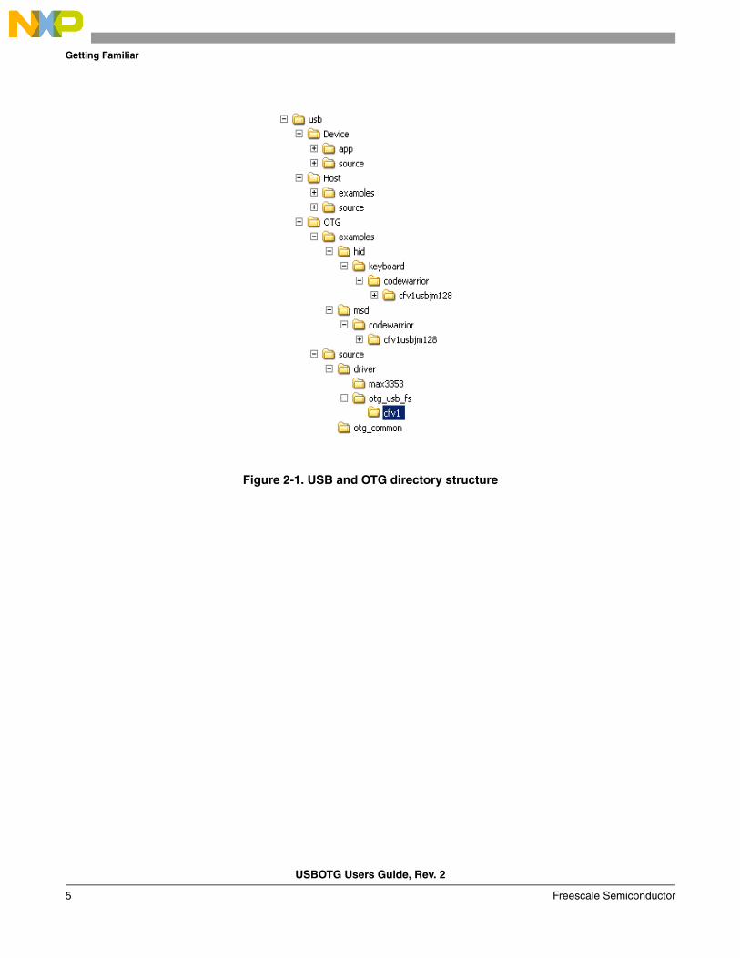
2.3 Directory structureThe software suite has a standard directory structure. One can extend it easily to accommodate more applications, classes, and low level drivers.
The following figure shows the USB directory structure that also contains the OTG functionality.
NOTEFigure 2-1 is provided as a reference and may not represent the latest version. For an up-to-date version, use the latest source code from the Freescale website.
Getting Familiar
USBOTG Users Guide, Rev. 2
5 Freescale Semiconductor
Figure 2-1. USB and OTG directory structure
USBOTG Users Guide, Rev. 2
Freescale Semiconductor 6
Chapter 3 On-The-Go (OTG) Architecture
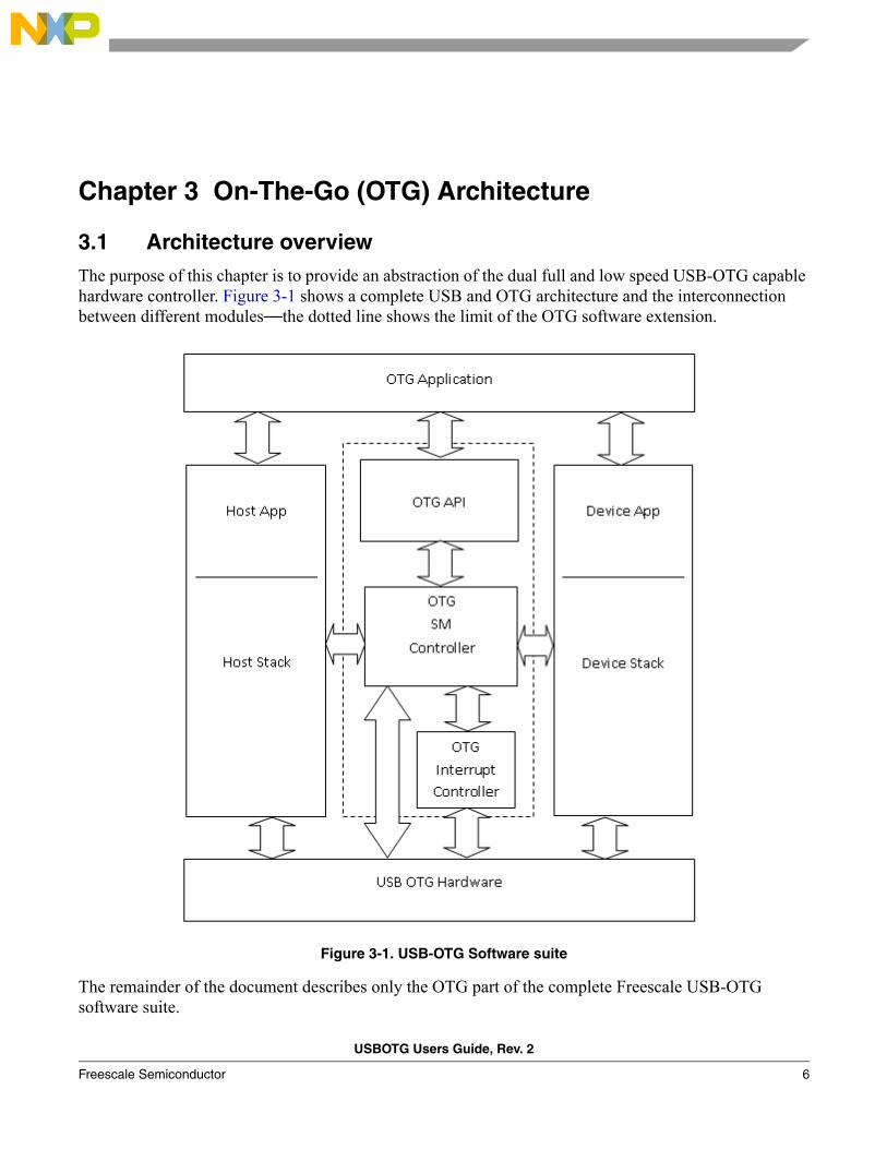
3.1 Architecture overviewThe purpose of this chapter is to provide an abstraction of the dual full and low speed USB-OTG capable hardware controller. Figure 3-1 shows a complete USB and OTG architecture and the interconnection between different modules—the dotted line shows the limit of the OTG software extension.
Figure 3-1. USB-OTG Software suite
The remainder of the document describes only the OTG part of the complete Freescale USB-OTG software suite.
On-The-Go (OTG) Architecture
USBOTG Users Guide, Rev. 2
7 Freescale Semiconductor
NOTEFor more information about the host stack structure and functionality or about the demo application for the different USB classes, please refer to the Freescale USB Stack with PHDC Host User Guide (document USBHOSTUG). For information related to Device Stack structure and specific applications, please refer to the Freescale USB Stack with PHDC Device User Guide (document USBUG).
3.2 OTG components overview
3.2.1 OTG application
The OTG application is responsible for initialization of the OTG environment (variables, and hardware support), registering of the application callback function, processing of the incoming event notifications from the bottom layer (typically in the application callback function), running the OTG task, handling the host or device application tasks according to user requirements, and the USB bus context. For each supported class, a generic demo application has been developed to show the basic functionality based on the interaction between two OTG-capable boards.
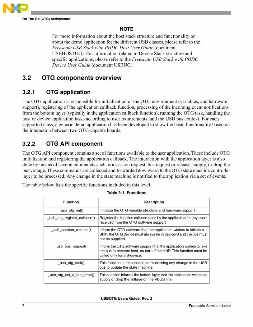
3.2.2 OTG API component
The OTG API component contains a set of functions available to the user application. These include OTG initialization and registering the application callback. The interaction with the application layer is also done by means of several commands such as a session request, bus request or release, supply, or drop the bus voltage. These commands are collected and forwarded downward to the OTG state machine controller layer to be processed. Any change in the state machine is notified to the application via a set of events.
The table below lists the specific functions included in this level:
Table 3-1. Functions
Function Description
_usb_otg_init() Initialize the OTG variable structure and hardware support
_usb_otg_register_callback() Register the function callback used by the application for any event received from the OTG software support
_usb_session_request() Inform the OTG software that the application wishes to initiate a SRP; the OTG device must always be in device-B and the bus must not be supplied.
_usb_bus_request() Inform the OTG software support that the application wishes to take the bus to become host, as part of the HNP. This function must be called only for a B-device.
_usb_otg_task() This function is responsible for monitoring any change in the USB bus to update the state machine.
_usb_otg_set_a_bus_drop() This function informs the bottom layer that the application wishes to supply or drop the voltage on the VBUS line.
On-The-Go (OTG) Architecture
USBOTG Users Guide, Rev. 2
Freescale Semiconductor 8
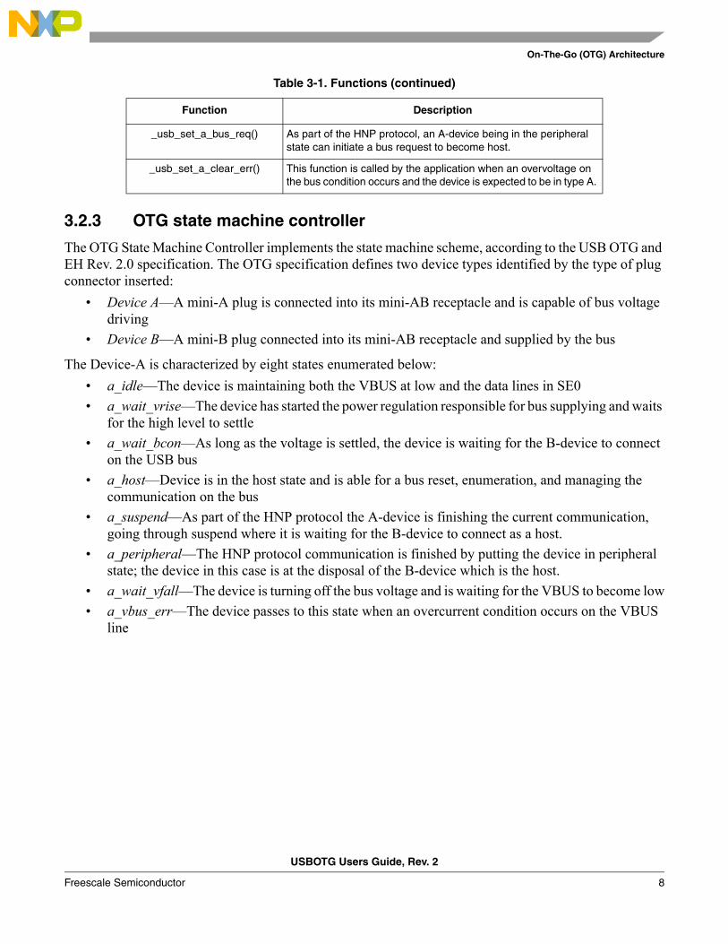
3.2.3 OTG state machine controller
The OTG State Machine Controller implements the state machine scheme, according to the USB OTG and EH Rev. 2.0 specification. The OTG specification defines two device types identified by the type of plug connector inserted:
• Device A—A mini-A plug is connected into its mini-AB receptacle and is capable of bus voltage driving
• Device B—A mini-B plug connected into its mini-AB receptacle and supplied by the bus
The Device-A is characterized by eight states enumerated below:
• a_idle—The device is maintaining both the VBUS at low and the data lines in SE0
• a_wait_vrise—The device has started the power regulation responsible for bus supplying and waits for the high level to settle
• a_wait_bcon—As long as the voltage is settled, the device is waiting for the B-device to connect on the USB bus
• a_host—Device is in the host state and is able for a bus reset, enumeration, and managing the communication on the bus
• a_suspend—As part of the HNP protocol the A-device is finishing the current communication, going through suspend where it is waiting for the B-device to connect as a host.
• a_peripheral—The HNP protocol communication is finished by putting the device in peripheral state; the device in this case is at the disposal of the B-device which is the host.
• a_wait_vfall—The device is turning off the bus voltage and is waiting for the VBUS to become low
• a_vbus_err—The device passes to this state when an overcurrent condition occurs on the VBUS line
_usb_set_a_bus_req() As part of the HNP protocol, an A-device being in the peripheral state can initiate a bus request to become host.
_usb_set_a_clear_err() This function is called by the application when an overvoltage on the bus condition occurs and the device is expected to be in type A.
Table 3-1. Functions (continued)
Function Description
On-The-Go (OTG) Architecture
USBOTG Users Guide, Rev. 2
9 Freescale Semiconductor
Device-B is defined by five states:
• b_idle—This state is characterized by the absence of the voltage combined with no bus activity
• b_srp_init—The device is going to request the start of a session
• b_peripheral—The device is in peripheral mode
• b_host—The device is acting as a host
NOTEOTG State Machine layer is responsible to load and unload the necessary host and peripheral stack when the appropriate state occurs.
3.2.4 OTG interrupt controller
The main role of the interrupt controller is to inform the state machine controller about any change in the bus signaling (rising or falling of the VBUS, data lines behavior), connecting or disconnecting of the device, respectively establishing the type of the device depending on the connector plug inserted. Any such event from the USB system is signaled to the State Machine Controller via an interrupt to the processor.
USBOTG Users Guide, Rev. 2
Freescale Semiconductor 10
Appendix A Working with the Software
A.1 IntroductionThis chapter gives you insight on how to use the Freescale USB Stack software. The following sections are described in this chapter:
• Preparing the setup
• Building the application
• Running the application
Knowledge of CodeWarrior IDE will be helpful to understand this section. While reading this chapter, practice the steps mentioned.
To take you through this chapter, the HID mouse application for the MC9S08JM60 is used as an example. For preparing the setup, building the application, and running the application the following devices— Kinetis, HC(S)08, ColdFire v1, and ColdFire V2—are used as an example.
A.1.1 Preparing the setup
A.1.1.1 Software setup
1. Double-click the Freescale_USB_Stack_v[current version].exe installer executable file.
2. The Freescale USB Stack Setup window appears. The following example shows the demonstration for USB Stack installation. You can follow the same instructions for new versions.
Example:
1. Click on the Next button to continue with Freescale USB Stack Setup installation.
Working with the Software
USBOTG Users Guide, Rev. 2
Freescale Semiconductor 11
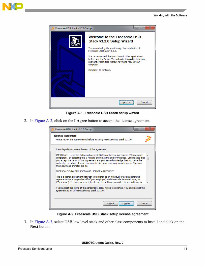
Figure A-1. Freescale USB Stack setup wizard
2. In Figure A-2, click on the I Agree button to accept the license agreement.
Figure A-2. Freescale USB Stack setup license agreement
3. In Figure A-3, select USB low level stack and other class components to install and click on the Next button.

Working with the Software
USBOTG Users Guide, Rev. 2
12 Freescale Semiconductor
Figure A-3. Freescale USB Stack components
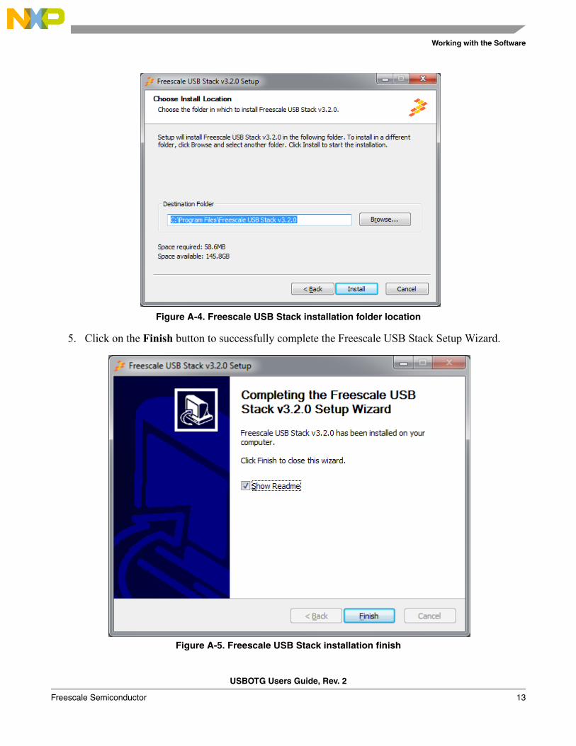
4. In Figure A-4, select the location of the folder where you require to install the Freescale USB Stack software and click on the Install button.
Working with the Software
USBOTG Users Guide, Rev. 2
Freescale Semiconductor 13
Figure A-4. Freescale USB Stack installation folder location
5. Click on the Finish button to successfully complete the Freescale USB Stack Setup Wizard.
Figure A-5. Freescale USB Stack installation finish
Working with the Software
USBOTG Users Guide, Rev. 2
14 Freescale Semiconductor
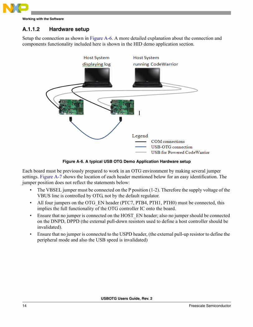
A.1.1.2 Hardware setup
Setup the connection as shown in Figure A-6. A more detailed explanation about the connection and components functionality included here is shown in the HID demo application section.
Figure A-6. A typical USB OTG Demo Application Hardware setup
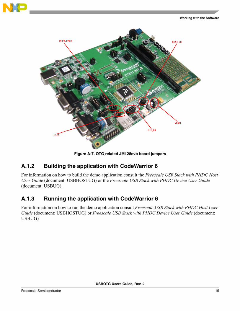
Each board must be previously prepared to work in an OTG environment by making several jumper settings. Figure A-7 shows the location of each header mentioned below for an easy identification. The jumper position does not reflect the statements below:
• The VBSEL jumper must be connected on the P position (1-2). Therefore the supply voltage of the VBUS line is controlled by OTG, not by the default regulator.
• All four jumpers on the OTG_EN header (PTC7, PTB4, PTH1, PTH0) must be connected, this implies the full functionality of the OTG controller IC onto the board.
• Ensure that no jumper is connected on the HOST_EN header; also no jumper should be connected on the DNPD, DPPD (the external pull-down resistors used to define a host controller should be invalidated).
• Ensure that no jumper is connected to the USPD header, (the external pull-up resistor to define the peripheral mode and also the USB speed is invalidated)
Working with the Software
USBOTG Users Guide, Rev. 2
Freescale Semiconductor 15
Figure A-7. OTG related JM128evb board jumpers
A.1.2 Building the application with CodeWarrior 6
For information on how to build the demo application consult the Freescale USB Stack with PHDC Host User Guide (document: USBHOSTUG) or the Freescale USB Stack with PHDC Device User Guide (document: USBUG).
A.1.3 Running the application with CodeWarrior 6
For information on how to run the demo application consult Freescale USB Stack with PHDC Host User Guide (document: USBHOSTUG) or Freescale USB Stack with PHDC Device User Guide (document: USBUG)
Working with the Software
USBOTG Users Guide, Rev. 2
16 Freescale Semiconductor
A.2 Setup HyperTerminal LogTo ensure that the application runs correctly as well as to send any OTG commands (that is, bus request, session request, drop the bus), the HyperTerminal application is used to send and get events to and from the devices connected. These following steps are used to configure the HyperTerminal application for one board and repeat the same steps to get the second board configured and ready-to-use.
1. Open the Windows HyperTerminal application by clicking the icon in Start\All Programs\Accessories\Communications path.
Figure A-8. Launch HyperTerminal application
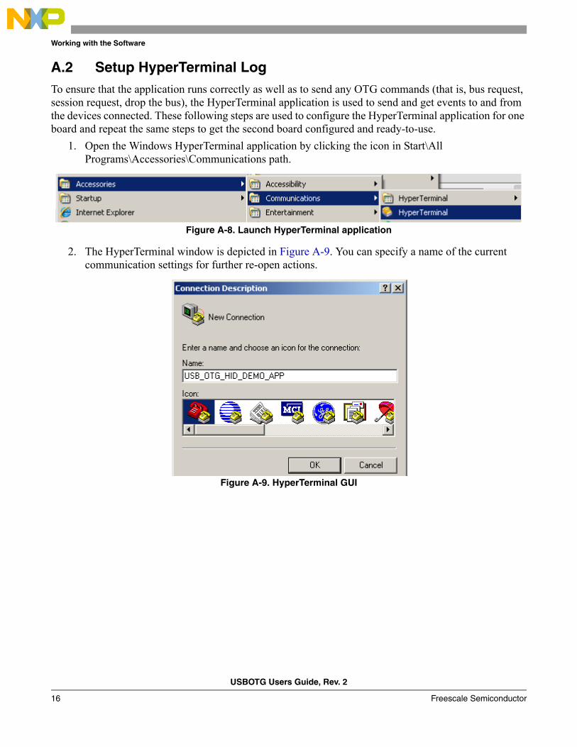
2. The HyperTerminal window is depicted in Figure A-9. You can specify a name of the current communication settings for further re-open actions.
Figure A-9. HyperTerminal GUI

Working with the Software
USBOTG Users Guide, Rev. 2
Freescale Semiconductor 17
3. Select the COM port, Figure A-10, it appears in the list as an emulated serial port.
Figure A-10. Connect using COM1
4. Figure A-11 explains the configuration of COM1 properties—the communication baud rate to 115200, data length to 8, no parity, one stop bit, and hardware flow control. Then click OK to complete the HyperTerminal configuration.
Figure A-11. Communication settings
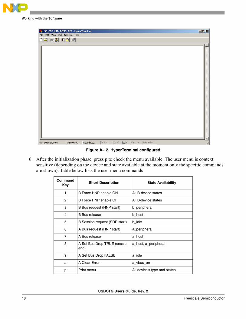
5. HyperTerminal is now configured and is shown in Figure A-12.
Working with the Software
USBOTG Users Guide, Rev. 2
18 Freescale Semiconductor
Figure A-12. HyperTerminal configured
6. After the initialization phase, press p to check the menu available. The user menu is context sensitive (depending on the device and state available at the moment only the specific commands are shown). Table below lists the user menu commands
Command Key
Short Description State Availability
1 B Force HNP enable ON All B-device states
2 B Force HNP enable OFF All B-device states
3 B Bus request (HNP start) b_peripheral
4 B Bus release b_host
5 B Session request (SRP start) b_idle
6 A Bus request (HNP start) a_peripheral
7 A Bus release a_host
8 A Set Bus Drop TRUE (session end)
a_host, a_peripheral
9 A Set Bus Drop FALSE a_idle
a A Clear Error a_vbus_err
p Print menu All device’s type and states
Working with the Software
USBOTG Users Guide, Rev. 2
Freescale Semiconductor 19
A.3 Uninstall the Freescale USB Stack with PHDC OTG Support1. From your computer click, Start > Settings > Control Panel > Add or Remove ProgramsFrom the
Add or Remove Program window select the Freescale USB Stack with OTG support then click Change/Remove
2. Click Yes on the uninstall message window
3. A message box appears. Click OK to complete the uninstall procedure.
USBOTG Users Guide, Rev. 2
Freescale Semiconductor 20
Appendix B Human Interface Device (HID) Demo
B.1 Setting up the demo
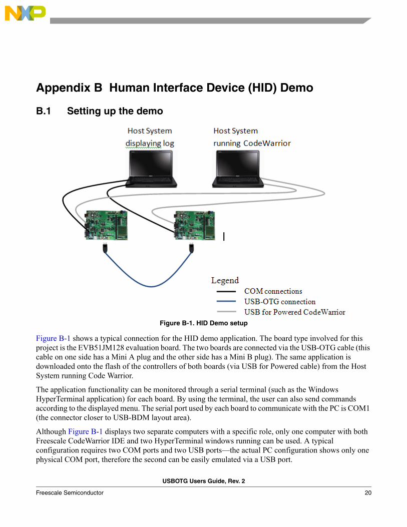
Figure B-1. HID Demo setup
Figure B-1 shows a typical connection for the HID demo application. The board type involved for this project is the EVB51JM128 evaluation board. The two boards are connected via the USB-OTG cable (this cable on one side has a Mini A plug and the other side has a Mini B plug). The same application is downloaded onto the flash of the controllers of both boards (via USB for Powered cable) from the Host System running Code Warrior.
The application functionality can be monitored through a serial terminal (such as the Windows HyperTerminal application) for each board. By using the terminal, the user can also send commands according to the displayed menu. The serial port used by each board to communicate with the PC is COM1 (the connector closer to USB-BDM layout area).
Although Figure B-1 displays two separate computers with a specific role, only one computer with both Freescale CodeWarrior IDE and two HyperTerminal windows running can be used. A typical configuration requires two COM ports and two USB ports—the actual PC configuration shows only one physical COM port, therefore the second can be easily emulated via a USB port.
Human Interface Device (HID) Demo
USBOTG Users Guide, Rev. 2
Freescale Semiconductor 21
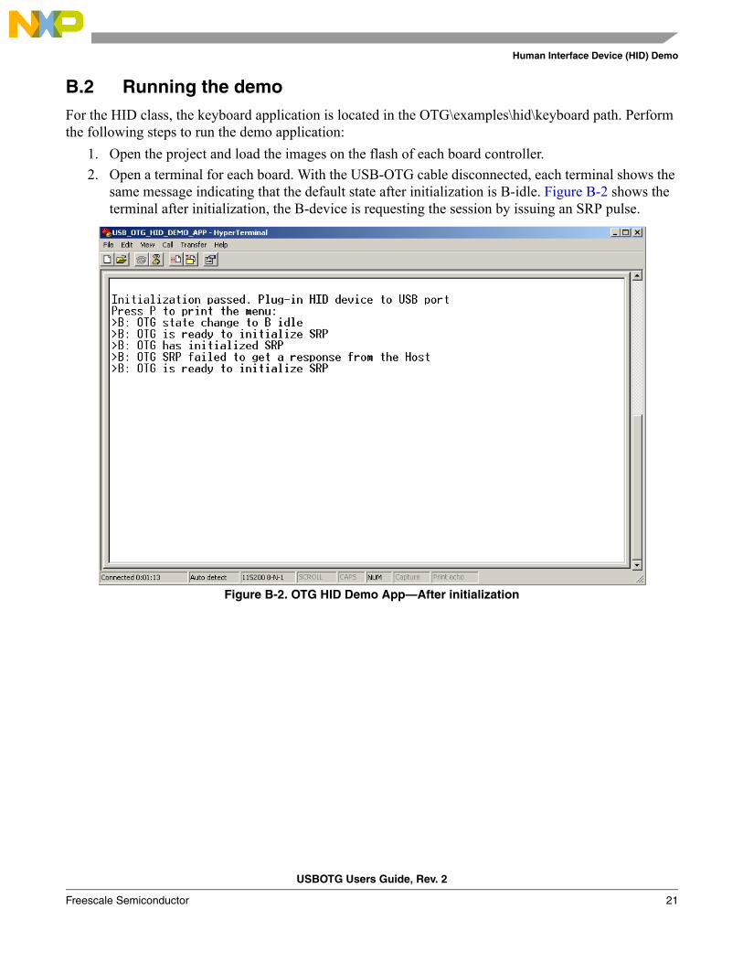
B.2 Running the demoFor the HID class, the keyboard application is located in the OTG\examples\hid\keyboard path. Perform the following steps to run the demo application:
1. Open the project and load the images on the flash of each board controller.
2. Open a terminal for each board. With the USB-OTG cable disconnected, each terminal shows the same message indicating that the default state after initialization is B-idle. Figure B-2 shows the terminal after initialization, the B-device is requesting the session by issuing an SRP pulse.
Figure B-2. OTG HID Demo App—After initialization
Human Interface Device (HID) Demo
USBOTG Users Guide, Rev. 2
22 Freescale Semiconductor
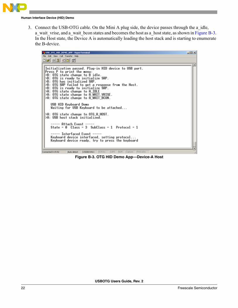
3. Connect the USB-OTG cable. On the Mini A plug side, the device passes through the a_idle, a_wait_vrise, and a_wait_bcon states and becomes the host as a_host state, as shown in Figure B-3. In the Host state, the Device A is automatically loading the host stack and is starting to enumerate the B-device.
Figure B-3. OTG HID Demo App—Device-A Host

Human Interface Device (HID) Demo
USBOTG Users Guide, Rev. 2
Freescale Semiconductor 23
4. On the B-device side, the peripheral stack is loaded, as shown in Figure B-4. At this moment, the B-device is used to emulate a keyboard—the push buttons located on the board corresponds to several keyboard keys. As for example: PTG1 > Page Down, PTG2 > Space, PTG3 > Print Screen
Figure B-4. OTG HID Demo App—Device-B Peripheral

Human Interface Device (HID) Demo
USBOTG Users Guide, Rev. 2
24 Freescale Semiconductor
5. To change the Host role (to initiate a HNP request), on the terminal attached to the B-device (the device that has attached the Mini B plug connector and is at the moment in a peripheral state) press the 3 key. After role changing the result is shown Figure B-5
Figure B-5. OTG HID Demo App—HNP request
Human Interface Device (HID) Demo
USBOTG Users Guide, Rev. 2
Freescale Semiconductor 25
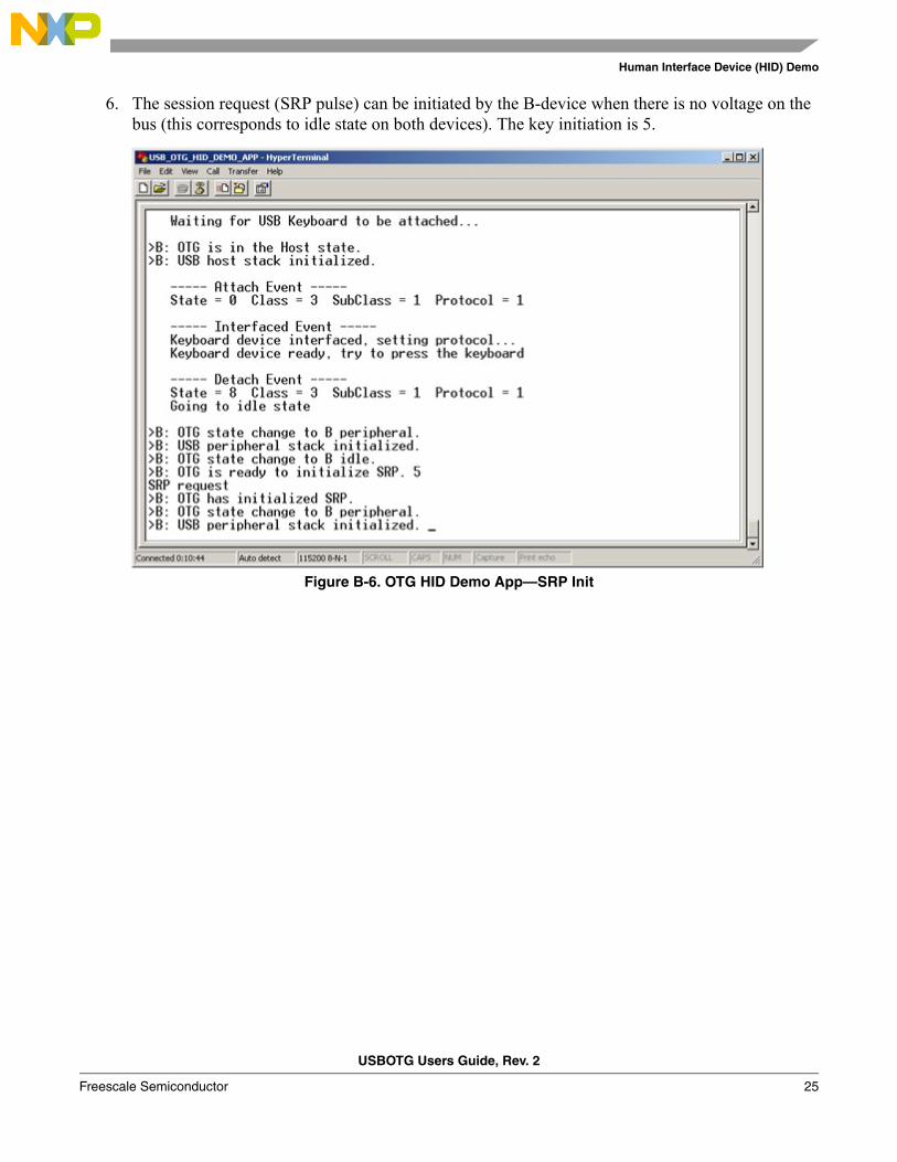
6. The session request (SRP pulse) can be initiated by the B-device when there is no voltage on the bus (this corresponds to idle state on both devices). The key initiation is 5.
Figure B-6. OTG HID Demo App—SRP Init
USBOTG Users Guide, Rev. 2
Freescale Semiconductor 26
Appendix C Mass Storage Device (MSD) Demo
C.1 Setting up the demoSetup the system as described in the Appendix B, “Human Interface Device (HID) Demo”.
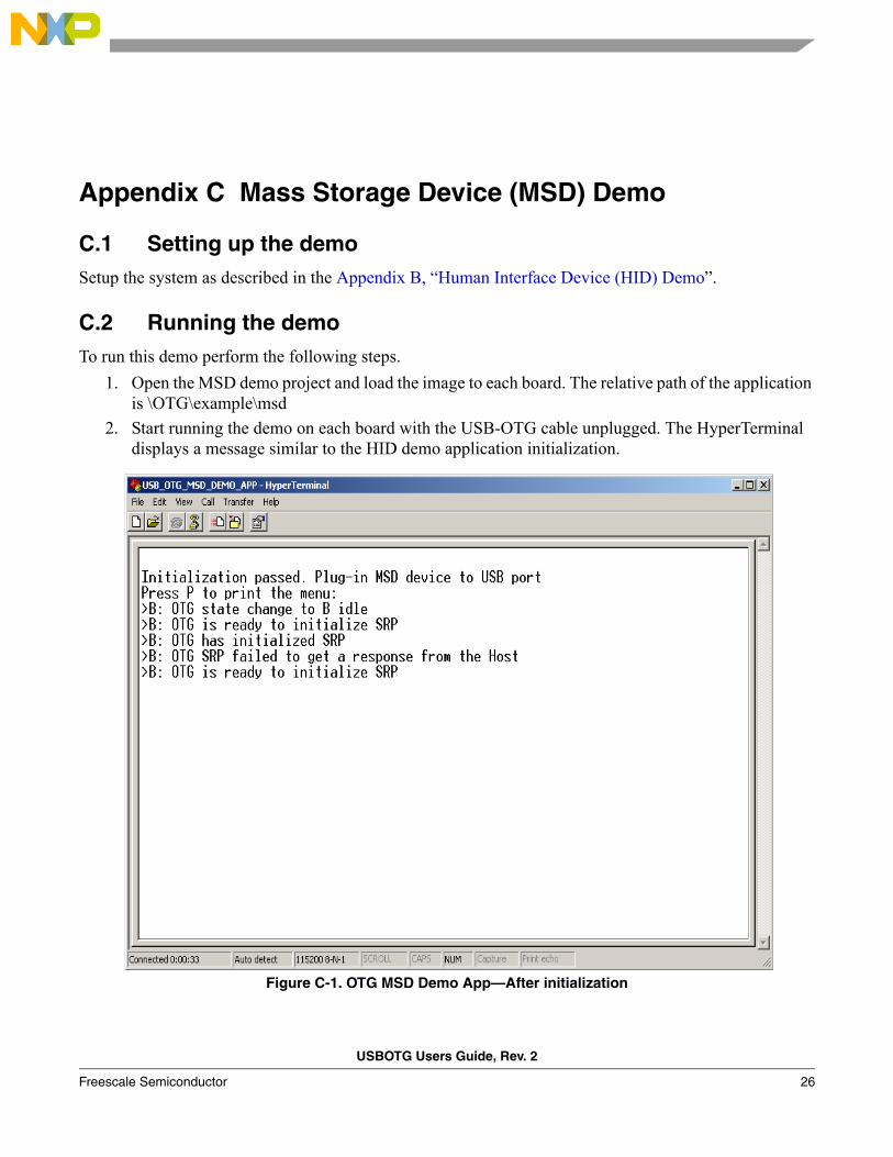
C.2 Running the demoTo run this demo perform the following steps.
1. Open the MSD demo project and load the image to each board. The relative path of the application is \OTG\example\msd
2. Start running the demo on each board with the USB-OTG cable unplugged. The HyperTerminal displays a message similar to the HID demo application initialization.
Figure C-1. OTG MSD Demo App—After initialization
Mass Storage Device (MSD) Demo
USBOTG Users Guide, Rev. 2
Freescale Semiconductor 27
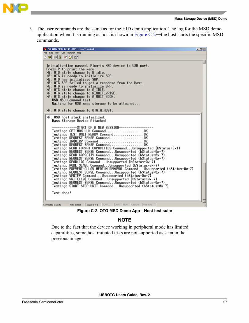
3. The user commands are the same as for the HID demo application. The log for the MSD demo application when it is running as host is shown in Figure C-2—the host starts the specific MSD commands.
Figure C-2. OTG MSD Demo App—Host test suite
NOTEDue to the fact that the device working in peripheral mode has limited capabilities, some host initiated tests are not supported as seen in the previous image.