free-surface · surface tension forces allow a curved surface to support a pressure drop according...
TRANSCRIPT

ON ATOMIZATION AND LINEARIZED FREE-SURFACE
INSTABILITY ON ROTATING BODIES
NZ
by
A. M. DRUMMOND
A. D Wod, Had . R.Thusto
Fligt Reearh Setio Dircto

SUMMARY
A surface-wave instability theory applicable to spin-ning discs and cups is presented and a new explanation of atom-ization from these devices is proposed. The theory predictsan unstable disturbance wavelength that correlates with experi-mental results of Hinze and Milborn for ligament formationfrom a rotating cup. The linear analysis is restricted to flowswhere perturbation amplitude is much less than film thickness.
Preceding page blank(iii)

TABLE OF CONTENTS
Page
SUMMARY ......................................................... (iii)
SYMBOLS ......................................................... (v
1.0 INTRODUCTION................................................
2.0 INVISCID SOLUT.ON ................................................ 1
2. 1 Disturbance Velocity Potential ................................... 22.2 Pressure Condition at the Free Surface ......................... 22.3 Surface Conditions for Velocity ............ ............... 22.4 The Equations of Motion ........................... ..... 32.5 Surface Shape ................................................ 32.6 Development of Stability Criteria ............................... 32.7 Effect of Parameters on Surface Stability......................... 62. 8 Maximum Instability with "Large" Film Thickness ............... 6
3.0 VISCOUS SOLUTION FOR "LARGE" DEPTH ......................... 7
3.1 Effect of Flow Rate ............................................. 83.2 Atomization and Instability......................................... 83.3 Comparison of Theory with Available Experiment!,1 Data.......... ... 10
4.0 CONCLUSION ........... ........ ................................. 11
5.0 REFERENCES ...................................................... 12
ILLUSTRATIONS
Figure Page
1 Schematic of Rotating Disc ........................................ 13
2 Representative Film Thickness on the Flat Portion and CircularArc Edge of a Spinning Disc .................................... 14
3 Representative Radial and Tangential Velocities at the FreeSurface on the Circular Arc Edge of a Rotating Disc ............... 15
4 Schematic of Edge Flow on a Rotating Disc .......................... 16
5 Schematic of the Stability Criterion for Inviscid Flow ................. 17
6 Stability Boundary and Fastest Growing Wave as a Function ofWeber Number for Inviscid Flow and Large Film Thickness ........ 18
7 Stability Boundaries as a Function of Reynolds Number andWeber Number for a Viscous Flow and Large Film Thickness ....... 19
(iv)

ILLUSTRATIONS (Cont'd)
Figure Page
8 Schematic of Free-Surface Divergence .............................. 20
9-11 Correlation of Theory and Experiment .............................. 21-23
SYMBOLS
Symbol Definition
a* Circumference of rotating body
a Amplitude of surface perturbation
C, C' Constants
d Drop diameter
D Disc diameter
g Acceleration of gravity
h, h, Depths of fluid and air layers respectively
h h/r
k 2rA/
K Constant
P. P' Pressure in fluid and air layers respectively
P", P" Steady pressure at free-surface in fluid and air layers respectively
p, p, Perturbation pressures in fluid and air layers respectively
Q Flow rate
Re Reynolds Number rVT /V
r Radius from axis of rotation
r' Perturbed free surface shape = r-
r., Radius of curvature on circular arc edge
r Local body surface slope
S p' coth kh'/p coth kh
T Surface tension
(v)
SYMBOLS (Cont'd)
Symbol Definition
t Time
V, Radial velocity component
V ,Tangential velocities of fluid and air respectively
W Weber Number rV 2 P/T
y Co-ordinate normal to free surface
z Number of ligaments
a Angle around circular arc edge
P, P' Density of fluid and air respectively. (pI .002378 slugs/ft)
01, ; Perturbation potentials of fluid and air respectively
77 Perturbation to free surface
X Disturbance wavelength
X.* X/27rr
X* Root of stability equation
X* Wavelength of fastest growing waveCRT
12 Absolute viscosity of liquid
Kinematic viscosity of liquid
Angular velocity
0 Azimuth angle around rotating body
V 2 Laplacian Operator
(vi)
-1-
ON ATCMIZATION AND LINEARIZED FREE-SURFACE
INSTABILITY ON ROTATING BODIES
1.0 INTRODUCTION
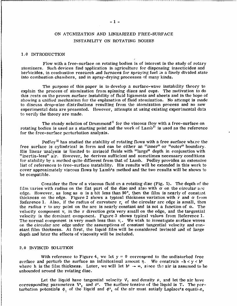
Flow with a free-surface on rotating bodies is of interest in the study of rotaryatomizers. Such devices find application in agriculture for dispensing insecticides andherbicides, in combustion research and furnaces for spraying fuel in a finely divided stateinto combustion chambers, and in spray-drying processes of many kinds.
The purpose of this paper is to develop a surface-wave instability theory toexplain the process of atomization from spinning discs and cups. The motivation to dothis rests on the proven surface instability of fluid ligaments and sheets and in the hope ofshowing a unified mechanism for the explanation of fluid atomization. No attempt is madeto discuss drop-size distributions resulting from the atomization process and no newexperimental data are presented. However, attempts at using existing experimental datato verify the theory are made.
The steady solution of Drummond" I for the viscous flow with a free-surface onrotating bodies is used as a starting point and the work of Lamb 2) is used as the referencefor the free-surface perturbation analysis.
Ped!ey 3) has studied the stability of rotating flows with a free surface where thefree surface is cylindrical in form and can be either an "inner" or "outer" boundary.His linear analysis is limited to inviscid fluids with "large" depth in conjunction with"inertia-less" air. However, he derives sufficient and sometimes necessary conditionsfor stability by a method quite different from that of Lamb. Pedley provides an extensivelist of references to free-surface instability. His results will be extended in this work tocover approximately viscous flows by Lamb's method and the two results will be shown tobe compatible.
Consider the flow of a viscous fluid on a rotating disc (Fig. 1). The depth of thefilm varies with radius on the flat part of the disc and also with a on the circular arcedge. However, as long as a is a bit less than 900, then the film is nearly of constantthickness on the edge. Figure 2 shows a typical thickness variation with r and a fromReference 1. Also, if the radius of curvature r, of the circular arc edge is small, thenthe radius r to any point on the arc is nearly constant and is not a function of a. Thevelocity component v, in the r direction gets very small on the edge, and the tangentialvelocity is the dominant component. Figure 3 shows typical values from Reference 1.The normal component is very much less than v,. We wish to investigate surface waveson the circular arc edge under the assumptions of constant tangential velocity and con-stant film thickness. At first, the liquid film will be considered inviscid and of largedepth and later the effects of viscosity will be included.
2.0 INVISCID SOLUTION
With reference to Figure 4, we let y = 0 correspond to the undisturbed freesurface and perturb the surface an infinitesimal amount ii. We constrain -h < y < h'where h is the film thickness. Later, we will let h' -- o, since the air is assumed to beunbounded around the rotating disc.
Let the liquid have tangential velocity VT and density p, and let the air havecorresponding parameters VIT and P'. The surface tension of the liquid is T. The per-turbation potentials P, of the liquid and €'1 of the air must satisfy Laplace's equation,

-2-
and the pressure must satisfy a surface conditioe to be discussed later at y = 0. Inaddition, the velocities normal to the free surface of liquid, air and the surface itselfmust be compatible. No flow is allowed when y = -h or h' since the disc is solid (y= -h)and the disturbance potential of the air (0'1) must be zero at the boundary of the air (y= h').
2. 1 Disturbance Velocity Potential
To satisfy the above requirements, we assume the following forms for the dis-turbance potentials 0 1 and '1, (Lamb2)):
01 = C cosh [k(y+h)] e i (a t -kre) (1)
'1 = C' cosh [k(y-h')] e(Qtkr0 ) (2)
where k = 2r/X and X is the wavelength of the disturbance. These forms satisfy Laplace'sequation (V 20 1 = 0, V2 0' 1 = 0), and the velocity conditions (30 1/ay = 0 at y = -h,a4, 1/Ay = 0 at y = h').
2 2 Pressure Condition at the Free Surface
Surface tension forces allow a curved surface to support a pressure dropaccording to the law
where R and R 2 are the free surface radii of curvature in the r, 0 plane and axial di-rections respectively (Lamb 2) p. 471). Now, 1/R1 = 1/r' - (d 2r'/d02 )/r 2 where r' isthe perturbed free surface shape. Here, r' = r+7 and 71 is the surface perturbationrelative to y = 0. From Lamb,
P-P'=T r1 1 2 _-q) 82 (r+1)'3P - P, = T _ _ 3
+r72 (r+) 2 a02 z 2(
In Equation 11 we will neglect variation of ?7 with z; i. e., in the direction ofthe spin axis (R 2 = co). Expanding Equation 3 and retaining only first order quantities ofi) and its derivatives results in
p p T T (17 + a2)
r 2 ! 2r
We assume that ,i<<2n/a8 2 . This term could be retained but little accuracy isgained when the angular velocity is large. The perturbation terms p and p? are hencerelated by the perturbation equation
P _ p, + T V71 = 0 (4)r2 a0 2 (4
2.3 Surface Conditions for Velocity
The conditions that the normal velocity of the fluids be the same as that o thefree surface for small deflections and that the tangential velocity is the only signif!cantvelocity component leads to:
+ = a (5)

-3y+ , T L
19t r DO C)y )
2.4 The Equations of Motion
The perturbation quantities must satisfy linearized forms of the equation ofmotion (Lamb):)
°°, +( P DO ,1j 0P - It I rDT) +(\- -Y1 - (-rf 2 sina+gcosa),q (7)
,Pt [(VT ( -0Y l
PIS + pt -( 1~ 1p \2
__ _ - at L( T r a--''-) + \-2 J - (-rn2 sina+gcosa)- (8)
where p and p, are perturbation pressures relative to the steady pressures P, and PI ,.The centrifugal force modifies the usual force potential in the last term of Equations 7and 8. When IR is large, it is reasonable to neglect g with respect to ra 2 . In any event,the angle a is nearly 90 °. Expanding Equations 7 and 8, neglecting steady terms andlinearizing we get the following perturbation equations:
p/P -" + T - + rg2 77 (9)
TF V-r D3',
pt/P = I + T + rn21 (10)
Under the assumptions, sinc is taken to be one.
2.5 Surface Shape
We assume that the perturbation to the surface elevation can bc written
1 = ae (i tkr 'e (11)Note that 3 2q/80 2 is (kr)2 17 justifying the approximation in Equation 4 for large k.
2.6 Development of Stability Criteria
We substitute Equations 1 and 11 in Equation 9 and obtain
p/p = [C cosh lk(y+h)} Ji(a-kVT)} + r 2 a]ei(O't° ' -r (12)
Similarly, Equations 2 and 11 substituted into Equation 10 yields
pt/pt = [C? cosh Jk(y-hI)1 1i(0-kV'T)l + rn 2a]ei (&I-k) (13)

4
We apply the pressure condition, substitute Equations 12 and 13 into Equation 4, sety = 0. retain only perturbations and simplify. The result is:
PC cosh kh(i)(o-kV ) - O'C' cosh kh'(i)(or-kV'T) = a['I'k - (P-P') rf 2] (14)
The surface condition. (Eqs. 5 and 6) yield:
C - ai(a-kVT)/(k sinh kh) (15)
C' + ai(o-kV',)/(k slnh kh') (16)
Substituting Equations 15 and 16 in Equation 14 results in:
P coth kh( - V,)' + P' coth kh'(k - V') ' = Tk - (P-P') rO '/k (17)
We solve for (a/k) in Equation 17 and let S = P' coth kh'/P coth kh and get
a VT + SVI T= 7 +S 1 + S
(18)
-(V - 2 - (I+S) (p/p)(p/p) - k
The wave speed is o/k.
Examination of Equation 18 shows that u will be complex (y+i6) if the quantityf(k) under the root sign is negative. From Equation 18,
2 L.r rU 2 (1-p'/p) _ -k(9f(k) - (V,-V') - (1+S)(P/P') L -k (19)
If f(k) is negative, then the perturbation amplitude r/ becomes
-q = ae (' + 'Ok; e" '
which is divergent. Hence, if f(k) from Equation 19 is less than zero, the wave isunstable. Setting f(k) equal to zero defines a boundary for stability. In the presentapplication, the relative velocity between the liquid and the stationary air (V, -V,) isjust rS2. Further, h' - - and the factor S reduces to (p'/p) tanh kh which is <<1. Thedensity ratio p,/p is also very small for air-liquid combinations. Hence, we approximateEquation 19 by
f(k) - (r1)2 (p/p') r - (20)
and obtain an approximate stability criterion. Equation 20 is quadratic in k. We define
= 2rr= (kr)- (21)
as a nondimensional disturbance wavelength. Substitution of Equation 21 in Equation 20
-. __. .- A

-5-
leads to the following expression for f(k*):
f(X*) -- X 2 + (p,/p)A* - 1/W 2! 0 (22)
where W is Weber's Number defined byrV 2 p
TW- T (23)
There is one real positive root to Equation 22 denoted by X*,. Figure 5 illus-trates the range of X* for stable or unstable waves.
Solving Equation 22 for X*, leads to the following limit on A* for unstablesurface waves:
X* > X*I
1+- (24)2 ,/) 2 w
If X* < A* an unstable surface wave results.
Pedley 3) neglected the air inertia (P' - 0) in his analysis but he did not make
the assumption 71 << a (Eq. 4). He quotes the result of Hocking4 I for the necessary and302
sufficient conditions for stability as
W < -(- +)
< when 7 <<2L (25)X*,2 ao 2
where the notation has been made to agree with this work. Setting p1 = 0 ill Equation 22lhads to A* 2 - 1/W for iistability, which is the same as Hocking's result. Since themaximum value of A* is one, and since there must be an integral number of wavelengthsin order for a periodic surface wave to exist, it is easily seen that N = 1,2,3 ..... nfor this special case. More generally, we can include the air inertia (p? j 0) and obtainfrom Equation 22
W -1 + (P/P)n n = 1,2,.... (26)
for instability. Properly, n > 10 for the approximation i <<-- Now pv/p is of302
order 10-3 for air-liquid interfaces, so that for n < 102, W -> n2 is a good approximation
to the instability criterion while for n - 104. W 2-- P is better. For W sufficiently
high, a wide range of disturbance wavelengths lead to an unstable free surface. Squire 5)
has shown that a sheet of liquid moving in still air is unstable provided the Weber Number(based on one half the sheet thickness) is greater than one. He quotes fair agreementwithl UJVL- -.ent.

2. 7 Effect of Parameters on Surface Stability
The surface tension enters the problem only in the Weber Number W. AsT - 0, W - and the stability criterion of Equation 22 reduces to
f*(X* + p'/p) > 0 (27) j
This is satisfied by all positive A* and shows the stabilizing effect of surface tension inthe sense that a smaller range of values of X* result when T 1 0.
The result of Equation 27 is reproduced by large values of r oi fQ. For agiven disc, the higher the angillar velocity the wider the range of X* for unstable waves.Hence, 02 is a "destabilizing" variable.
The density ratio pt/p can vary by choice of liquid (P) and its temperature aswell as by varying ambient conditions of air temperature and pressure (P'). The additionof P'/0 acts in a destabilizing sense. Increasing p acts in a stabilizing sense while theconverse is true for p'.
2. 8 Maximun Instability with "Large" Film Thickness
Some disturbance wavelength in the unstable region maximizes the imaginarypart of a, leading to a "fastest growing" disturbance. From Equations 18 and 21 we obtainthe following expression for a:
V1V i pt/p tanhkh [g(*) 28)
whereT I
g(x*) = VXT + (P/p')V2t.* - (P/p') TI (29)
The hyperbolic tangent is nearly I when kh is greater than about 1. 5. In this sense, welet kh be "large", and let tanh kh = I in Equation 28. The result for the im,'ginary partof a is:
i g(O /(30)
r , 2
The condition for maximum instability is:
o(31)
or
d 0gx)U7 0 (32)
The operation indicated by Equation 32 is applied to Equation 29 which results in:3
A* + 2(p'/p)X* W- 0 (33)
for finite X*.
q 1 --I :1i' 1 : I i ~ [ l '--ii ...:l I *lwhom ,

-7-
Equation 33 is quadratic in A* and it has one root (X*Rtz) within the unstable region:
X* = (p/P) -1 + 1 + 3 ] (34)
Disturbances with wavelength equal to X*CRIT are those which grow the fastest. Substi-tuting Equation 34 in Equation 28 leads to the corresponding complex value of or. Notethat 1A*cRIT must be an integer leading to the conchsion that very often there is nophysically possible solution to Equation 34. Hence any X* in the unstable range is equallylikely. The higher the Weber Number, the more lik.ly a solution to Equation 34 becomes.
Integral values of (X*)-1 and (X*CRI) - wer. chcsen and the corresponding WeberNumber for p = 1.65 slugs/ft 3 and TiP = .0015 ft 3/see ' was computed from Equations 24and 33. The results are shown in Figure 6. Properly, the points should not be joined bya smooth curve.
For many liquids, T/P does not vary outside the range 0. 5 x 10 - 3 to 2.5 x 10 - 3.
Below a certain speed, the waves are stable. For example, for (kX)- l = 10, the wavesare stable for r3 2 < .148, (T/p = .0015). The smaller the radius, the higher thisminimum speed becomes. It is seen that X*CRIT i0 close to VI\. For W < 105, log (X*)'lis approximately a linear function of log W with a slope of .52. Hence, for inviscidfluids, (X*)- ' = W, 52 + constant.
3.0 VISCOUS SOLUTION FOR "LARGE"1 DEPTH
Lamb 2) (p. 627) considers surface waves of a stationary viscous fluid. He
concludes that the wave velocity is very nearly the same as for an inviscid solution butthat the amplitude of the wave is attenuated approximately by a factor e-2k 2
t. The par-ameter v is the kinematic viscosity of the liquid. Harrison" ) has analyzed the viscousproblem'more accurately and we interpret Lamb's result as applying when P',V,<<pv,. Therestriction is easly met for air-liquid interfaces even if v'>v. Further, the flow irro-tationality assumption becomes more approximate the nearer one gets to the disc surfacesince viscous forces increase as y - -h. Therefore, we add a further condition that theresults will be accurate only when h> X. In this event, the factor S from Equation 18is just p'/p, and we restrict ourselves to large depth solutions.
With the above comments in mind, we replace Equation 11 by
= ae-2 k2 ,e(Ot k ') (35)
and retain the wave velocity or/k from Equation 18. A slight revision of the instabilitycriterion is necessary. As before, let a = y ± i6 and substitute it into Equation 35 andobtain
il = ae(-2vk2 +6)t e i(I t- kr8 (36)
From Equation 36, 71 will be divergent if
m(k) = -2vk 2 + 6 0 (37)
Using Equation 28 to evaluate 6, we have
-2vk 2 + k f 2 0 (38)
for an Instability criterion where g(k) is given by Equation 29. As before, we substitute

-8-
(kr)- 1 and solve for X*:
h(X*) = A*' + (P'/p)X* - (1/W)X* - 4/Re 2 - 0 (39)
One positive real root of Equation 39 always exists and, defines a stability boundary. Twonegative real roots always exist. Figure 7 shows the stability boundary as a function ofReynolds Number for various values of Weber Number. Values of P, and P are the sameas those for Figure 6.
All the curves coalesce at low Reynold's Number which shows that the stabilityboundary for very viscous fluids is insensitive to surface tension.
Each stability boundary in Figure 7 tends to rise linearly and then roll off tothe inviscid assymptote as Reynold's Number increases. The roll-off point is a functionof Weber Number. The linear portion can be approximated by
- Re r + C
When viscosity is zero (Re - ,o) then Equation 39 yields the same roots as itsinviscid counterpart Equation 23. The addition of viscosity results in a smaller regionof unstable wavelengths and hence is said to exert a "stabilizing' influence on the freesurface.
The wave velocity of the unstable viscous fluid is identical with the inviscid and
equals the tangential velocity VT. The wave is stationary with respect to the disc.
3. 1 Effect of Flow Rate
For a given fluid, disc and speed, the value of h depends only on the flow rate.An approximate equation for hU) is:
After some manipulation, the most useful form for h is:
( 67r ) 1/3
\a*2 ReV,/where a* is the circumference of the rotating body and r is the local slope. It is seenthat h varies as
As a - 7T/2 r - 0 leading to a large film thickness but E is nearly constantfor a range which ends quite close to a = ff/2. It is easily seen that a very small filmthickness can result from high values of VT and Re or low values of Q. Hence, smallvalues of X* are physically possible that are well within the limitations that X<2h.
3.2 Atomization and Instability
The above theory on surface instability is applied in the formulation of a newtheory on the mechanism of atomization from rotating bodies. Consider the sketch inFigure 8. When X*>X* , the free surface is unstable, 17 tends to h as time progressesand a volume of liquid equal to 2X2 h is trapped in the shaded area. Since , is periodic in0 (period = X*), the number of "sites" of formation is constant around the body, and theamount of flow to any site is X*Q ft 3/sec Macfarlane and Colbourn") have verified thisexperimentally.

-9-
Using Equations 18 and 35, we can write
?= e n('A e . (40)
( n + i 17(41)
If n is large, then the perturbation grows rapidly. The phase shift between nand p is about 900 because fl and n are large while X* is small. The result is a largeoutward velocity over the rising portion of the wave and a corresponding large inwardvelocity over the falling portion of the wave. Hence, the trapped volume will leave therotating body normal to the free surface with a considerable amount of internal rotation.Three types of atomization have been experimentally observed6.7) from rotating discs andcups:
1) direct drop formation at low Q,
2) ligament formation at moderate Q,
3) sheet formation at high Q.
Ligaments decay into drops by Rayleigh-type surface instability of rotationallysymmetric columns of fluids, while sheets decay into ligaments by a surface instability(Hagerty and Shea8
) or Dombrowski and Johns9)) and subsequently into drops by Rayleighinstability. The flow rate Q determines which type of atomization results. Now, if X2 h,the volume of trapped fluid, is greater than X*QAt, the flow to the site, then type 1 atom-ization results in an intermittent manner because it takes a finite time to replenish thefluid and rebuild the fluid layer for a subsequent unstable ejection of fluid. However, ifX2h is about equal to X*QAt, then continuous ejection of ligaments must occur in order tosatisfy the continuous flow. Obviously, the third condition of sheet ejection results whenX*QAt is greater than X
2 h. Probably At will have to be studied experimentally, but itprobably is related to n(X*) (Eq. 40).
If the instability criterion is not met, then the linear approximation predicts astable flow which separates as a sheet from the rotating body independent of the flow rate.If the flow rate is low, then the film is very thin resulting in a very short sheet which veryquickly decays to drops.
Historically, the accepted mechanism of drop formation from the edge of a dischas been to equate the mass of the drop times its centripetal acceleration with the surfacetension force based on the drop circumference. The correlation function due to Waltonand Prewett 10) is
dS2 N = constant (42)
dM?2 -- = constant (42)
where d is the drop diameter. The constant in Eq-ation 42 did not correlate well usingexperimental values of parameters on the lefthand side.
The only steady surface tension effects are the rise of fluid in a capillary tubeand the ability of the curved free surface to support a steady pressure difference. Theformer requires fluid contact on both sides of a tube normal to the free surface while thelatter Is subtracted out exactly from the perturbation equations. Therefore, surfacetension forces arise only from altering the curvature of the steady free surface due tofree-surface perturbations. Only when the surface Is "stretched" should ourfnec forcesbe considered. Hence it Is unsatisfying to equate surface tension forces whose origin isIn unsteady phenomena with centripetal accelerations which are steady when n is constant.

- 10 -
Raylcigh instability of fluid ligaments arises from a surface instability and now a consist-ent drop formation process from rotating discs based on surface instability is proposed.1linze and Milborn 7) applied an instability approach in attempting to explain and correlatetheir experimental results. However, their point of view was qualitative and was usedonly to collect variables in functional groups for experimental determination of a constantand ar. exponent. Pedley3 1 hints at surface instability being involved in atomization ofswirling liquid jets.
As the amplitude of the surface wave increases, the linearized form of theequations presented here becomes less accurate and the X* of the ac~ual wave may differfrom the theoretically predicted value. However, if a non-linear system is unstable toan infinitesimal disturbance, so is its linearized approximation. Hence, the extension ofthe proposed drop formation process to real situations is immediate.
3.3 Comparison of Theory with Available Experimental Data
Experimental work which supplies sufficient data to calculate X* is sparse.Either the fluid or the operating conditions are not completely documented. However, anexception is the paper by Hinze and Milborn71, although even their method of presentationleaves doubt as to the values of all the parameters for any specific data point. Theirmain contribution to the present comparison is a semi-empirical relation for the numberof ligaments shed from a rotating cup. They present the relation
Z= K /P2D+nPTD 4+n (3
for the number of ligaments. K and n were found to be . 215 and 4/5 from experiment.A reasonably large amount of scatter (+25%) existed. In the notation of this paper andnoting z aquals 1/A* we get (from Eq. 43):
X* = 1/(. 577Re0 W 114) (44)
In arriving at this equation, Hinze and Milborn allowed Q to vary provided thatthe flow rate was not high enough to produce a sheet and yet high enough to exclude directdrop formation. In addition, data for three different liquids were presented.
They noted a "liquid torus" formed at the lip of the cup. This is a reasonablesituation since the steady radial velocity of the liquid varies from zero on the cup surfaceto a maximum at the free surface and the inward directed normal velocity has the samebehaviour resulting in a tendency for the liquid to flow around the edge of the cup lip.Hence, the approximation of a in the stability equations being equal to 900 is appropriate.
The results of the stability analysis using parameter values within the experi-mental range are compared with the experimental results of the three liquids as well asthe overall correlation function (Eq. 44) on Figures 9 to 11. The viscosity of the liquidswas the major variation between them.
On Figure 9, the experimental data for the least viscous liquid virtually coin-cided with the viscous stability boundary, as did the overall correlation function. Thecomparison is very good. Increasing viscosity (Fig. 10) showed the overall correlationfunction close to the viscous stability boundary but the particular liquid curve showedsome discrepancy. The highest viscosity liquid (Fig. 11) was within the stable region aspredicted by the viscous boundary, but was within the unstable region from the inviscidboundary. Apparently non-linear and rotational flow effects have become important. Ingeneral, the comparison is favourable considering the comments on scatter and variable

- 11 -
Q already made. This tends to substantiate the theory of this report. When the theorypredicts instability, Hinze and Milborn's data show ligaments. The only area wherediscrepancies occur is for very viscous liquids.
A further check on experimental results was made from a photograph byMacfarlane and Colbourn" ) showing atomization by direct drop formation from the edgeof a spinning disc. The picture was a shadowgraph taken looking vertically down on a13.40 sector of a one-inch diameter disc. The regularity of drop formation sites wasevident ar.d 23 were counted at the rim of the sector. The angular velocity was 313 revo-lutions p(.r second. Regarding each drop site as a wavelength, it was easy to calculateA* = 3. 2 X 10- 3 . The fluid data were not specified but by using T/p of 1. 2 x 10- 3, p'/pof 1.4 x 10- 3 , and v = 10 - 4 (the fluid was a light fuel oil) the inviscid and viscous boundarycalculations for At were 1.5 x 10- 3 and 2.2 x 10- 3 respectively. Therefore. the theorydid predict an unstable surface wave and the proposed atomization model was not contra-dicted.
However, Stuar t 2 , in his review artic!e on non-linear effects in hydrodynamicstability; points out that Poisseuille Flow can be unstable due to non-linear effects whenthe flow is predicted to be stable by linearized theory. There may be an energy transferfrom the perturbed motion to the mean motion by Reynold's Stresses which distort themean flow. Rosenhead13
) states that non-linear terms do not act to stabilize a flow andthat plane Couette Flow is unstable for finite disturbances even though it is stable forinfinitesimal disturbances. The linear theory is thus considered to be somewhat restric-tive since it does not account for any energy transfers between the mean and perturbedmotions.
Lamb 2) (p. 417) discusses waves of finite amplitude. The free surface of a
quiescent liquid of infinite depth takes on an "approximately trochoidal form" whichsharpens the crests and flattens the troughs of the sine wave predicted by linear theory.This is exactly what the pictures of Hinze and Milborn show for ligament formation, i. e.the space between the ligaments is greater than a ligament diameter.
The linearized theory is valid only when a/A is small (Lamb 2 ) p. 417). In otherwords, the amplitude of the surface wave must be much less than its wavelength. Forirrotationality, h must be greater than X/2. Therefore, the wave amplitude is restrictedto being much less than h. For atomization, the amplitude must equal the film thicknesswhich leads to the conclusion that the linearized theory can only be used to test for incip-ient instability.
4.0 CONCLUSION
A surface-wave instability theory has been presented to attempt an explanationof drop and ligament formation from edges of rotating discs and cups. Sheet formationhas already been explained by the separation of the fluid from the edge of the rotating discby the steady flow theory (Drummond'). Pedleys 3a results have been extended. Somecorrelation between theory and experimental results of Hinze and Milborn 1 and Macfarlaneand Colbourn") have been shown which tends to substantiate the theory. However, thelinear theory may be too restrictive and non-linear as well as rotational flow effects maybe large during the actual fluid shedding from the disc edge.
Atomization from sheets and I.olated lig.aments has already been explained byfree-surface instability, and now atomization from rotating cups and discs has been put inthe same' framework. Some experimental work Is needed to provide data on edge wavesand their breakdown.
-12-
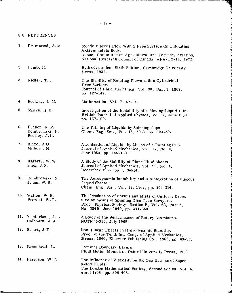
5.0 REFERENCES
1. Drumrnnwd, A. M. Steady Viscous Flow With a Free Surface On a RotatingAxisymmetric Body.Assoc. Committee on Agricultural and Forestry Aviation,National Research Council of Canada, AFA-TN-10, 1972.
2. Lamb, H.I Hydrodyn Lmics, Sixth Edition, Cambridge UniversityPress, 1932.
3. Pedley, T. J. The Stability of Rotating Flows with a CylindricalFree Surface.Journal of Fluid Mechanics, Vol. 30, Part 1, 1967,pp. 127-147.
4. Hocking, L. M. Mathematika, Vol. 7, No. 1.
5. Squire, H. B. Investigation of the Instability of a Moving Liquid Film.British Journal of Applied Physics, Vol. 4, June 1953,pp. 167-169.
6. Fraser, R. P. The Filming of Liquids by SDinning Cups.Dombrowski, N. Chem. Eng. Sci., Vol. 18, 1963, pp. 323-337.Routlev, J.H.
7. Hinzc, J.O. Atomization of Liquids by Means of a Rotating Cup.Milborn, H. Journal of Applied Mechanics, Vol. 17, No. 2,
June 1950. pp. 145-153.
8. Hagerty, W. W. A Study of the Stability of Plane Fluid Sheets.Shea, J. F. Journal of Applied Mechanics, Vol. 22, No. 4,
December 1955, pp. 509-514.
9. Dombrowski, N. The Aerodynamic Instability and Disintegration of ViscousJohns, W. R. Liquid Sheets.
Chem. Eng. Sci., Vol. 18, 1963, pp. 203-214.
10. Walton, W.H. The Production of Sprays and Mists of Uniform DropsPrewett, W. C. Size by Means of Spinning Disc Type Sprayers.
Proc. Physical Society, Section B, Vol. 62, Part 6,No. 354B, June 1949, pp. 341-350.
11. Macfarlane, J. J. A Study of the Performance of Rotary Atomisers.Colbourn, A.J. NGTE 11-310, July 1969.
12. Stuart, J. T. Non-Linear Effects in Hydrodynamic Stability.Proc. of the Tenth Int. Cong. of Applied Mechanics,Stresa, 1960, Elsevier Publishing Co., 1962, pp. 63-97.
13. Rosenhead, L. Laminar Boundary Layers.Fluid Motion Memoirs, Oxford University Press, 1963.
14. Harrison, W. J. The Influence of Viscosity on the Oscillations of Super-posed Fluids.The London Mathematical Society, Second Series, Vol. 6,April 1908, pp. 396-405.

- 13 -
cr LL
uiUcU,
9- 0-
B a cr

144
zCD_ 0
00
wo
0 zo z
S0 Cz'~~~
w-~u.
>
b14 0D LLC
:r.~. COc-)0.~

- 15 -
w
w
0 U-"
0 L--
S-o z
I-.
-o
z a>0-
0>
NJ
"0 .
: zo
oas/ in .
(n Ui0 _
:)as 4 - 4
L0
Cw ]
j.Ic IIID
0 o 0
U-O

16 -
y I
yh
y :-h
FIG.4: SCHEMATIC OF EDGE FLOW ON A ROTATING DISC

-17-
S*)
FIG,5: SCHEMATIC OF THE STABILITY CRITERION FORINVISCID FLOW

- 18o-
0 L
_ _w - j
LLl
-~Z 0
cox z
>LLJ
I cx J
+ - 0
_ _ _ _ _ _ _ _ _ I_ _q____ M____ v___ cot, kD I?

-19-
,-ir
I I w
Q LL.I> w
9-.w (Dw41 w2
CD 0
-1-- -1
IL LL.
0-I
- - N j
ti-~__ D __

-20-
.~cr0
w
00
-t w6
41L

-21-
rrTr
0: 0' /a
10 0
z
~~(NJ
-~ EQ ~ I -
a q -I-I- LL
f-I ID In /n to

-22-
I w4 2F
-1 J 0
00
N =j (P (
~. ~-,~ -' /cFc

-23-
I w
0 00
-J .
0 to
. 1 0
a-'~ 04_ 1 _
Zr 0
00
-. a, aD P o W.I -