frame co-addition - california institute of...
TRANSCRIPT
National Aeronautics and SpaceAdministrationJet Propulsion LaboratoryCalifornia Institute of Technology
1FJM
WISE Science Data Center CDR – January 29-30, 2008
Frame Co-addition
Frame Co-addition
Frank MasciIPAC/Caltech

National Aeronautics and SpaceAdministrationJet Propulsion LaboratoryCalifornia Institute of Technology
2FJM
WISE Science Data Center CDR – January 29-30, 2008
Frame Co-addition
WSDS Multi-frame Pipeline
Level-0Frames
FrameIndex
Meta-data
Static &Dynamic
InstrumentalCalibration
PartialScan/Frame
Pipeline
Source Detection/Extraction
BG matchingCoadd
DetEx
2MASSRef. list
Level-3Coadd
Level-1bFrames
Level-3Source list
RA,Dec,flux,etc.
SelectFrames
Exec Pipelines
Multi-framePRex
PRex
Upsample, Coadd
Level-1bFrames
Outlier rejection
Work imagestaging
Meta-data
Framelist
Framelist
Coadd
Coadd
Level-1bSourceLists
Manual Start
QA reports
Gen QAreports
QA
Meta-data

National Aeronautics and SpaceAdministrationJet Propulsion LaboratoryCalifornia Institute of Technology
3FJM
WISE Science Data Center CDR – January 29-30, 2008
Frame Co-addition
Requirements (Level 4)
From the WSDC Functional Requirements Document (Version 2.0; 25 November 2007):
• L4WSDC-001: The WSDC shall produce a digital Image Atlas that combines multiple surveyexposures at each position on the sky.
• L4WSDC-004: The WSDC shall release the final WISE digital Image Atlas, Source Catalogand Explanatory Supplement within 17 months of the end of on-orbit data collection.
• L4WSDC-005: The WSDC shall generate a preliminary digital Image Atlas using data fromthe first 50% of the sky that is surveyed.
• L4WSDC-008: The WSDC shall release the preliminary WISE Image Atlas, Source Catalogand Explanatory Supplement within 6 months of the end of on-orbit data collection.
• L4WSDC-022: The photometric calibration of the final WISE Image Atlas shall be tied to thephotometric calibration of the final WISE Source Catalog.
• L4WSDC-023: The WSDC shall make all WISE image data available in accordance to theFlexible Image Transport (FITS) astronomical data standard.
• L4WSDC-021: The images in the final WISE Image Atlas shall be re-sampled to a commonpixel grid at all wavelengths.
• L4WSDC-078: The WISE science data products shall use the International Celestial ReferenceSystem (ICRS) to describe the positions and motions of celestial bodies. WISE astrometry shallbe mapped into the ICRS using the 2MASS All-Sky Point Source Catalog as the primaryastrometric reference.
National Aeronautics and SpaceAdministrationJet Propulsion LaboratoryCalifornia Institute of Technology
4FJM
WISE Science Data Center CDR – January 29-30, 2008
Frame Co-addition
Requirements continued..
• L4WSDC-047: The WSDS Pipeline processing shall combine multiple image frames coveringeach point on the sky to form the Atlas Images, and construct coverage maps that encode thenumber of image frames contributing to each pixel of the Atlas Images.
• L4WSDC-026: The WSDC shall generate and archive coverage maps that show the number ofindependent observations that go into each pixel of the Image Atlas images in each band. Thecoverage numbers shall take into account focal plan coverage and losses due to poor dataquality, low responsivity and/or high noise masked pixels, and pixels lost because of cosmicrays and other transient events.
• L4WSDC-084: The WISE Image Atlas shall be constructed by combining all available scienceimages covering the sky. This does not include image pixels rejected because of lowresponsivity, high dark current or read noise, transient behavior such as charged particleimpacts, or scattered light due to moon proximity.
• L4WSDC-051: The WSDC shall make the WISE catalog and image products available to thecommunity via the internet through appropriate web-based tools.
• L4WSDC-086: The web-based interface to the WISE Image Atlas shall allow the user to viewand retrieve an image in any of the four WISE bands with any specified center (tangent point)and any size up to at least 1° × 1°.

National Aeronautics and SpaceAdministrationJet Propulsion LaboratoryCalifornia Institute of Technology
5FJM
WISE Science Data Center CDR – January 29-30, 2008
Frame Co-addition
Requirements continued..
• L4WSDC-041: As a goal, the WSDC shall combine image data from multiple orbits andextract sources from the combined images at intervals of no shorter than 3 days and no longerthan 30 days to generate a temporary, intermediate combined image archive and sourcedatabase for the purpose of science data quality assessment by the WISE Science Team andWSDC.
• L4WSDC-080: The final WISE Source Catalog shall have greater than 99.9% reliability forsources detected in at least one band with SNR>20, where the noise includes flux errors due tozodiacal foreground emission, instrumental effects, source photon statistics, and neighboringsources. This requirement shall not apply to sources that are superimposed on an identifiedartifact. => Relates to reliability of outlier detection and flagging.
• L4WSDC-063: The WSDC shall work with the WISE Science Team to validate that the ImageAtlas and Source Catalog satisfy WISE science requirements prior to their release.

National Aeronautics and SpaceAdministrationJet Propulsion LaboratoryCalifornia Institute of Technology
6FJM
WISE Science Data Center CDR – January 29-30, 2008
Frame Co-addition
Deliverables (Co-add products)
• Digital Image Atlas will consist of co-adds that combine multiple frame exposures within pre-defined regions on the sky in each of the four bands: 3.3, 4.7, 12 and 23µm
• For each band, the plan is to have three products (all same dimensions, pixel sizes):– Main intensity co-add image– Associated depth-of-coverage map indicating effectively the number of unmasked (good)
pixel contributions– Uncertainty co-add image that contains the 1-σ error estimate in the co-add signal for
every pixel
• Explanatory supplement:– Methodology– Recipes on using products (uncertainties and coverage maps) to perform source
photometry

National Aeronautics and SpaceAdministrationJet Propulsion LaboratoryCalifornia Institute of Technology
7FJM
WISE Science Data Center CDR – January 29-30, 2008
Frame Co-addition
Tiling Geometry
• Two logical options for the Atlas Image tile sizes and pixel scales are as follows.• Case 1: 4096 × 4096 pixels at 1 arcsec/pixel (schematic at an equatorial pole is below):
– Linear tile sizes: ~1.137 degrees;– Position angles of all image tiles are zero;– A minimum linear overlap between any two adjacent tiles of 2 arcmin in both Dec and RA;– Tiles are aligned within 163 iso-declination bands.– Number of tiles on the sky = 34162– Required storage assuming 4 Bytes/pixel, 12 products/tile = 27.51 TB

National Aeronautics and SpaceAdministrationJet Propulsion LaboratoryCalifornia Institute of Technology
8FJM
WISE Science Data Center CDR – January 29-30, 2008
Frame Co-addition
Tiling Geometry continued..
• Case 2: 4096 × 4096 pixels at 1.375 arcsec/pixel (=1/2 native pixel size):– Linear tile sizes: ~1.564 degrees;– Position angles of all image tiles are zero;– A minimum linear overlap between any two adjacent tiles of 3 arcmin in both Dec and RA;– Tiles are aligned within 119 iso-declination bands.– Number of tiles on the sky = 18241– Required storage assuming 4 Bytes/pixel, 12 products/tile = 14.69 TB
• Tiling arrangement, sizes, overlaps and pixel scales are all configurable parameters and will be fixed beforegenerating the final Image Atlas.
• Given 4 bands and 3 co-add products per band (intensity, uncertainty and coverage), this means 12 productsper tile (or footprint) on the sky.⇒ from above geometries, expect Atlas Image archive to be ~28 TB and 15 TB (uncompressed) for pixel
scales of 1 and 1.375 arcsec/pixel respectively.
• Atlas Image products will be accessed via a WISE image server interfacing with IRSA. Users will be able toretrieve a co-add portion based on sky location, spatial extent, orientation and pixel scale.– Archive presentation later today will discuss this further.

National Aeronautics and SpaceAdministrationJet Propulsion LaboratoryCalifornia Institute of Technology
9FJM
WISE Science Data Center CDR – January 29-30, 2008
Frame Co-addition
COADD Pipeline Overview
INPUTS:- instrumentally and phot. calibrated, pointing refinedscience frames (level-1B): bands 1-3:10162; band 4: 5082;- bad-pixel masks (also records opt artifacts, latents);- uncertainty (sigma) frames;- list is queried from region centered on predefined sky tile.
Interpolate frames (using kernel optimized foroutlier detection) onto common pixel grid.
Outlier detection on interp. pixel stacks usingrobust methods (e.g., median, MADs,quantiles) → Frame masks updated.
- Gain/throughput matching (multiplicative) so toscale input frames to single photometric zero-point.- Frame background matching (additive).
Co-addition of all good (unmasked) detectorpixels using AWAIC: A WISE Astronomical ImageCo-adder. Uses a more optimal interpolationprocedure with uncertainty weighting.
OUTPUTS:- main intensity image (rate ∝DN/t units), MAGZP in headers.- coverage map/image- uncertainty image- 4096 x 4096; ≤1.375″/pix (TBD)- QA metrics: backgrounds, noise,coverage distributions.
Atlas Image FPG;products registered indatabase and indexed.Will interface with IRSA’sWISE image server.
Check and rescale (if necessary) error modeluncertainties against variance in repeatedframe measurements (χ2 stats).
Outlier detection & flagging

National Aeronautics and SpaceAdministrationJet Propulsion LaboratoryCalifornia Institute of Technology
10FJM
WISE Science Data Center CDR – January 29-30, 2008
Frame Co-addition
Background Matching
• Goal: obtain seamless (or smooth) transitions between frames across overlaps in a co-add. We want toequalize background levels on frame-to-frame scales but preserve natural background variations if possible.
• Varying background levels mainly due to varying instrumental effects and transients.
• Within Atlas Image tiles (~1° – 1.5°), we can tie the levels of the frames to a single value - e.g., the median ora sigma-clipped average of all the input levels, or, to the median values in frame overlap regions (the 2MASSmethod).
• We want to first make each Atlas Image tile self-consistent for scientific purposes.
• Then need a general background matching method for internally stitching tiles together in the WISE imageserver. E.g., a user may query a region that straddles a tile boundary.
– Only performed if background levels between adjacent tiles significantly differ (outside background uncertainties).– Nice methods have already been developed, e.g., Montage, Spitzer (MOPEX, MIPSGAL project)– These use “global minimization algorithms”. To prevent solutions from veering off to large ridiculous values, we need a
constraint, e.g., tie to absolute (DIRBE) background with a smoothly varying scale factor, or, large scale averages.
• Derive a single photometric zero-point for a co-add from input zero-point values. This may involve possiblescaling of input frame levels if systematics are severe. Done before offset matching above.
National Aeronautics and SpaceAdministrationJet Propulsion LaboratoryCalifornia Institute of Technology
11FJM
WISE Science Data Center CDR – January 29-30, 2008
Frame Co-addition
Outlier Detection
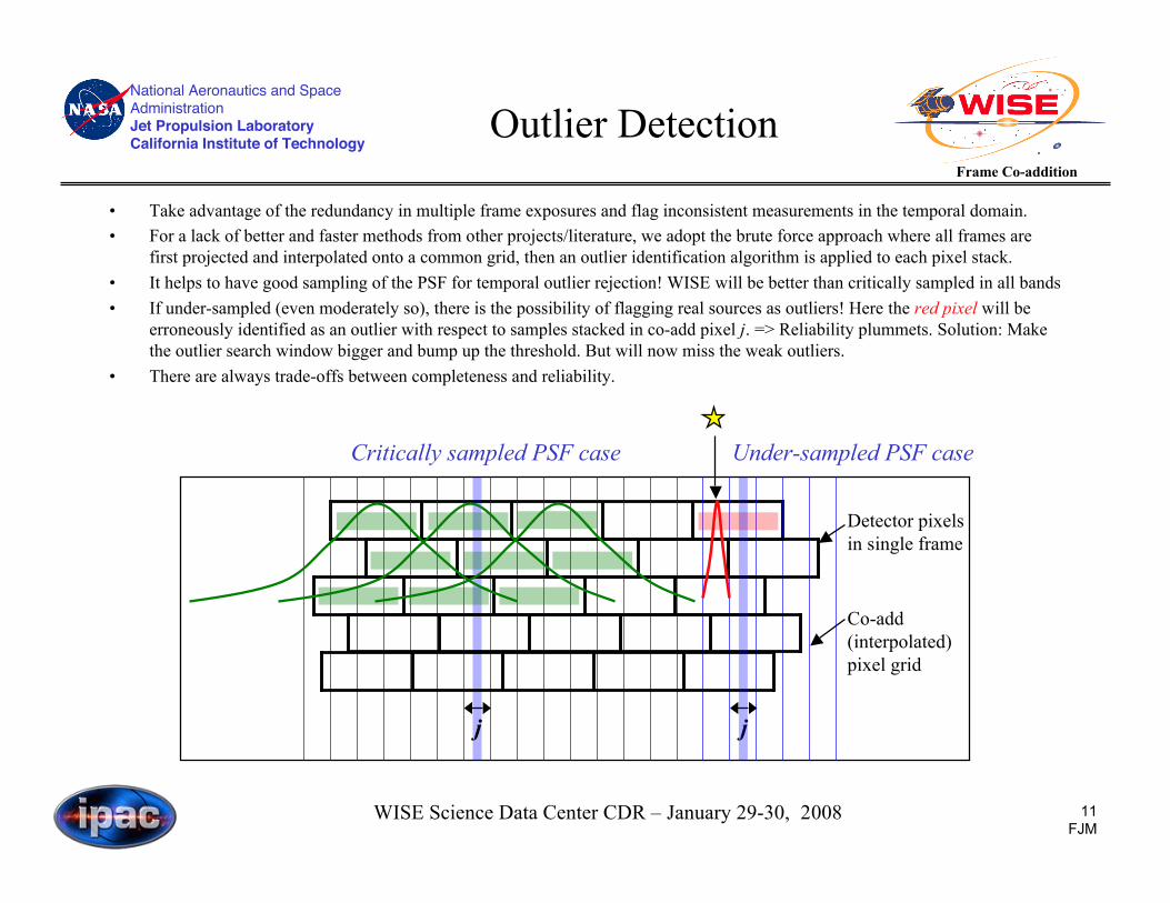
• Take advantage of the redundancy in multiple frame exposures and flag inconsistent measurements in the temporal domain.• For a lack of better and faster methods from other projects/literature, we adopt the brute force approach where all frames are
first projected and interpolated onto a common grid, then an outlier identification algorithm is applied to each pixel stack.• It helps to have good sampling of the PSF for temporal outlier rejection! WISE will be better than critically sampled in all bands• If under-sampled (even moderately so), there is the possibility of flagging real sources as outliers! Here the red pixel will be
erroneously identified as an outlier with respect to samples stacked in co-add pixel j. => Reliability plummets. Solution: Makethe outlier search window bigger and bump up the threshold. But will now miss the weak outliers.
• There are always trade-offs between completeness and reliability.
j
Under-sampled PSF caseCritically sampled PSF case
j
Detector pixelsin single frame
Co-add(interpolated)pixel grid

National Aeronautics and SpaceAdministrationJet Propulsion LaboratoryCalifornia Institute of Technology
12FJM
WISE Science Data Center CDR – January 29-30, 2008
Frame Co-addition
Outlier Detection method..
Main steps:1. Project and interpolate frame pixels onto a common grid and store values from all pixel stacks. To circumvent memory
overflow, we can partition the grid into sub-areas, then identify outliers in each separately.2. For each pixel stack in interpolated space, compute robust moment measures of their flux distribution and save as image
files on disk (for later QA), e.g., median and sigma measures from either quantiles or the MAD measure:
3. Test an interpolated pixel with value pi in stack j for “outlier status” if it satisfies the following criteria:
4. Flag outliers in frame-processing (bad-pixel) masks to propagate downstream5. When building the final co-add, read in the masks and omit outlier pixels entirely from the co-add.
• Above method provides an independent robust measure of sigma as represented by the redundantmeasurements across multiple frame exposures; ⇒ use to check (and re-scale) the computed sigmas thatare initiated upstream using an error model.
• Moving objects (asteroids) will be flagged as outliers unless they’re moving slowly (<~ PSF widthbetween the nominal 94 minute orbits) - e.g., Kuiper belt, trans Neptunian objects.⇒ Co-adds will represent the “static” inertial sky.
!
" j # 0.5(p84 $ p16) or " j #1.483 median pi $median pi{ }{ }
!
pi > median pi{ } + tthres" j
or
pi < median pi{ }# bthres" j

National Aeronautics and SpaceAdministrationJet Propulsion LaboratoryCalifornia Institute of Technology
13FJM
WISE Science Data Center CDR – January 29-30, 2008
Frame Co-addition
Co-addition Goals
• To optimally combine all the available measurements into a faithful representation of the sky given all theinstrumental effects, limitations, transients, cosmic rays etc.. have been accounted for.
• Another way of looking at this (which I prefer) is to ask: what model or representation of the sky propagatesthrough the measurement process to yield the observations within measurement error?
• The measurement process is effectively a filtering operation performed by the instrument’s Point ResponseFunction (PRF):
• The PRF represents the real transfer function. Each pixel collects light (information) from its vicinity with anefficiency described by the PRF. The better the sampling, the larger its domain of awareness.
• The PRF represents the most optimal interpolation kernel for use in co-addition and ‘reconstructing the sky’from the measurements. For detector measurements Di , the flux in a co-add pixel j is given by:
• In co-adders that use overlap-area weighted averaging (e.g., MOPEX, Montage, other..), the interpolationweights are the actual overlap areas rij = aij. In fact, for severely under-sampled PSFs, the above methodreduces to area-weighted averaging. In this limit, the PRF becomes top-hat.!
f j =
rijDi
i
"
riji
" ; rij = response at location j from a detector pixel at i.
!
Sky" PSF #$PRF
1 2 4 3 4 % sampling by pixels" measurements

National Aeronautics and SpaceAdministrationJet Propulsion LaboratoryCalifornia Institute of Technology
14FJM
WISE Science Data Center CDR – January 29-30, 2008
Frame Co-addition
Co-addition in AWAIC
AWAIC - A WISE Astronomical Image Co-adder. What makes it ‘wise’?Advantages of AWAIC over other co-adders for WISE (e.g., MOPEX, 2MASS, Montage):• PRF interpolation reduces the impact of bad/masked pixels if the data are well sampled (even close to critical).
This leads to effectively non-zero coverage at bad pixel locations on sky due to the extended PRF tails.• Uncertainty estimation from a propagated error model, χ2 sanity checks, and correlated noise corrections.• The output signal and noise co-adds can be combined to define the most optimal matched filter for point
source detection.– High frequency noise is smoothed out without affecting the point source signal sought for => SNR of peaks is maximized.– This will benefit processing at the WSDC since a source catalog is one of its release products.– See Ken Marsh’s presentation on MDET (point source detection).
• Allows for any interpolation kernel to be specified, i.e., matched to the observations.• Is capable of resolution enhancement (HIRES) through a Richardson-Lucy like procedure. Note: this is not in
the WISE baseline plan. Used for offline research later.
Disadvantages:• An extended interpolation kernel will “smear” sharp-edged features such as CR spikes on the co-add grid.
These can masquerade as real sources if not properly flagged beforehand. Smearing is minimized in area-weighted (or top-hat PRF) interpolation methods where spike artifacts remain more pronounced.
• Noise is correlated on larger spatial scales in the co-add when a broader kernel is used. Correlations areminimized for compact (top-hat) PRFs. Correlated noise must be accounted for when performing photometryoff the co-add - either aperture or profile fitting.

National Aeronautics and SpaceAdministrationJet Propulsion LaboratoryCalifornia Institute of Technology
15FJM
WISE Science Data Center CDR – January 29-30, 2008
Frame Co-addition
AWAIC Processing Flow
INPUTS:- instrumentally and photometrically calibrated, backgroundmatched science frames with best (refined) WCS and distortionin FITS headers; queried from DB within predefined region.- accompanying “bad” pixel masks (with suspect outliers flagged)- accompanying uncertainty (sigma) frames;- list of FPA position-dependent PRFs.- Processing params: pixel size ratios, desired WCS of co-add
Set-up output WCS of co-add (internal) cellgrid onto which an up-sampled PRF withsame pixel scale is mapped. Location anddimension of co-add grid (tile) predefined.
Initializations, check inputs for consistency,assign defaults.
AWAIC BRAIN: Main processing loop (seemore detailed flowchart): project pixels withdistortion correction; map and interpolatedetector PRF values onto internal cell grid;build up “mean” co-add using PRF-weightedaveraging; optionally iterate if HIRES desired.
Down-sample and trim all internal cell gridproducts to desired final co-add pixel scaleand dimensions.
OUTPUTS:- Main intensity image;- Uncertainty image;- Depth-of-coverage map;- Log of I/O, processing status and runtime;- QA diagnostics;
NOTES- Projection and distortion correction uses “fastalgorithm” developed at Spitzer and also used inMontage.- flux = PRF / inverse-variance weighted average:
!
f j =
rij
" i
2Di
i
#
rij
" i
2
i
#

National Aeronautics and SpaceAdministrationJet Propulsion LaboratoryCalifornia Institute of Technology
16FJM
WISE Science Data Center CDR – January 29-30, 2008
Frame Co-addition
PRF Placement andInterpolation
Desired co-add pixel
Internal working cell pixel
• PRF is sampled on same scale as an internal cell pixel (offline calibration once cell size optimized).
• Flux from cell pixel contributing to measured flux in detector pixel i = rij * fi
• At end, co-add values in cell grid are down-sampled to desired final co-add pixel scale.
PRF centered on detector pixel (unit normalized)
Single detector pixel
Cell pixel j with flux fj
PRF pixel with value rij= PRF value atcell pixel j (⇒ nearest neighbor), or usebi-linear interpolation.

National Aeronautics and SpaceAdministrationJet Propulsion LaboratoryCalifornia Institute of Technology
17FJM
WISE Science Data Center CDR – January 29-30, 2008
Frame Co-addition
North Ecliptic PoleSpitzer-IRAC
~ 40′
WISE Touchstone fieldCombines AWAICmosaics in IRAC bands:3.6µm (blue),4.5µm (green), and5.8µm (red).
Zoom in - PTO

National Aeronautics and SpaceAdministrationJet Propulsion LaboratoryCalifornia Institute of Technology
18FJM
WISE Science Data Center CDR – January 29-30, 2008
Frame Co-addition
North Ecliptic Pole(3.6µm co-add zoom-in)
Input raw (instrumentally calibrated) frames Coverage image map
Output co-add cutout
Outliers
galaxy

National Aeronautics and SpaceAdministrationJet Propulsion LaboratoryCalifornia Institute of Technology
19FJM
WISE Science Data Center CDR – January 29-30, 2008
Frame Co-addition
Example: NGC 2403Spitzer-IRAC (3.6µm)
~ 10′

National Aeronautics and SpaceAdministrationJet Propulsion LaboratoryCalifornia Institute of Technology
20FJM
WISE Science Data Center CDR – January 29-30, 2008
Frame Co-addition
Noise Characterization
• Simulated 500 independent, randomly dithered frames containing Poisson noise, then co-added.• Co-add pixel noise scales as expected with the number of frame overlaps (depth-of-coverage):
!
" p #1
N frames

National Aeronautics and SpaceAdministrationJet Propulsion LaboratoryCalifornia Institute of Technology
21FJM
WISE Science Data Center CDR – January 29-30, 2008
Frame Co-addition
Summary from Peer Review
• Peer review on frame co-addition was held November 15, 2007 at IPAC.
• Main discussions, recommendations and suggestions:
– Rules of thumb provided on optimum pixel sizes and number of frames for outlier detection frompeople’s Spitzer experiences.
– Existence of drastic trade offs between completeness and reliability when detecting outliers in low-to-moderate coverage cases.
– Potential biases when weighting inputs using Poisson derived variances.– Use WISE cyclotron test data as input for testing outlier detection algorithms.– Artifacts from the Rice-(de)compression can be flagged using temporal outlier detection methods.– Pitfalls of global minimization methods for background matching when there are no absolute constraints.– Spatially varying flat-fielding residuals in input frames may wreck havoc since they cannot be corrected
by most simple background matching algorithms.– Physical meaning of fractional versus integral coverage values can lead to confusion.– Possible large Inter-pixel Capacitance (IPC) effects may exist in the background limited bands (3 and 4).
This will broaden PRFs and exacerbate correlated noise in co-adds.– A mosaic of the standard deviations across repeated observations has proved to be very useful on Spitzer.– Not to spend too many resources on HIRES’ing if not in baseline plan.

National Aeronautics and SpaceAdministrationJet Propulsion LaboratoryCalifornia Institute of Technology
22FJM
WISE Science Data Center CDR – January 29-30, 2008
Frame Co-addition
Development Schedule
• Version 0 - 10/15/2007: prototype and dataflow infrastructure– Basic co-addition with bad pixel masking complete
• Version 1 - 7/17/2008: input test / simulation data with signatures from ground characterization– Selection of specific mask bits to flag against using specifiable bit-string template– Outlier detection and rejection implemented. Completeness/Reliability analysis– Uncertainty model versus repeatability checks and input uncertainty rescaling– Frame background (gain/throughput and offset) matching implemented, rescaling of
calibration zero points in co-add headers– Sky tiling geometry for Image Atlas settled: dimensions and pixel sizes– IRSA-WISE image server capabilities, infrastructure and budgeting
• Version 2 - 2/28/2009: mission scenario testing using simulations and Spitzer data– Frame co-addition pipeline thread/wrapper– QA diagnostics and metrics on Atlas Image tiles defined and implemented; trackback utility– Sky tiling and frame indexation/querying scheme in place with DB infrastructure– Atlas Image stitching/background matching algorithms (for IRSA image server) designed– Atlas Image FITS and DB metadata defined
National Aeronautics and SpaceAdministrationJet Propulsion LaboratoryCalifornia Institute of Technology
23FJM
WISE Science Data Center CDR – January 29-30, 2008
Frame Co-addition
Development Schedule
• Version 3 - 8/4/2009: operations readiness testing, launch, IOC– Optimization: analytic fits to input PRFs; FFTs to speed up convolution steps (TBD)– Noise-correlation correction factors to assist aperture photometery off co-adds (for
explanatory supplement)– Final Product Generator (metadata integrated with image server)
• Version 3.5 - 1/26/2010: tune-up pipelines/modules according to on-orbit performance– Input parameter tuning: outlier thresholds, interpolation accuracy, masking bit templates– Point Response Functions (versus array location, brightness[IPC?] if necessary) derived– Further optimization (if needed)– Quality assurance (with feedback to other subsystems): e.g., temporal variations from frame
stacks at poles to tune upstream instrumental calibrations, distortion, pointing accuracy.– Start to distill documentation/analysis pages into Explanatory Supplement
• Version 4 - 10/18/2010: reprocessing (final processing pass)– Tune up: derive best or scan-matched PRFs, thresholds, optimized to support final
reprocessing– HIRES improvements for offline use/research.

National Aeronautics and SpaceAdministrationJet Propulsion LaboratoryCalifornia Institute of Technology
24FJM
WISE Science Data Center CDR – January 29-30, 2008
Frame Co-addition
Further reading
• Summary of WISE co-adder with examples: http://web.ipac.caltech.edu/staff/fmasci/home/wise/awaic.html
• Subsystem Design Specification (SDS): http://web.ipac.caltech.edu/staff/fmasci/home/wise/sds-wsdc-D005-v2.8-awaic.pdf
• Atlas Image tiling geometry examples: http://web.ipac.caltech.edu/staff/fmasci/home/wise/tiling.html