frame 2011 users manual
TRANSCRIPT

version 2011.10
F.R.A.M.E. 2011
Users’ Manual
Copyright : Erik De Smet, Offerlaan 96, B 9000 GENT Belgium
F.R.A.M.E.
2
Introduction. ................................................................................................................. 3 BASIC PRINCIPLES ........................................................................................................ 4 DEFINITIONS AND BASIC FORMULAS............................................................................... 5 USING THE RESULTS ..................................................................................................... 6 THE PRACTICAL CALCULATION. ....................................................................................... 7
Spreadsheet build-up. ................................................................................................. 7 Use. .......................................................................................................................... 8
The “Info FRAME” page. ................................................................................................. 9 The summary. .......................................................................................................... 10 Calculation of the Orientation Value Ro, the initial risk. .................................................. 12
The “Info P” page. ....................................................................................................... 13 Fire load factor q. ..................................................................................................... 13
Sub factor immobile fire load density Qi. ................................................................... 13 Sub factor mobile fire load density Qm. .................................................................... 14
Fire spread factor i. ................................................................................................... 15 Sub factor m, the average dimension. ...................................................................... 15 Sub factor T, temperature rise. ................................................................................ 16 Sub factor reaction to fire class M. ........................................................................... 16
The area factor g. ..................................................................................................... 17 The level factor e:..................................................................................................... 18 The venting factor v: ................................................................................................. 18 The access factor z: .................................................................................................. 19
The P-REF page. ......................................................................................................... 20 The “Info A” page. ....................................................................................................... 22
The activation factor a. ............................................................................................. 22 The evacuation time factor t ...................................................................................... 23 The content factor c. ................................................................................................. 25 The dependency factor d: .......................................................................................... 26
The Acceptable Risk page. ........................................................................................... 27 The info D page. .......................................................................................................... 29
The water supply factor W ......................................................................................... 29 The normal protection factor N. .................................................................................. 30 The special protection factor S ................................................................................... 31 The fire resistance factor F ......................................................................................... 32 The escape factor U and the salvage factor Y: .............................................................. 33
The Protection Level page: ........................................................................................... 34 The P- V1, A- V1, D- V1, P- V2, A- V2 and D- V2 pages. ................................................... 37 Special compartment types. .......................................................................................... 39
Atrium compartments. .............................................................................................. 39 Lofts and duplexes. ................................................................................................... 41

Introduction. “FRAME” means Fire Risk Assessment Method for Engineering. It is a method developed to
make systematic fire risk evaluations for buildings, based on the combination of severity,
probability and exposure of fire. “FRAME” is a development of the Swiss Gretener method,
which was published in the 1970’s.
I developed “FRAME” originally as a tool to help me as fire protection engineer to define a
sufficient and cost effective fire safety concept for new or existing buildings. Unlike building
codes that are mostly meant to assure a safe escape or rescue for the occupants, "FRAME"
also aims at protecting the building, its content and the activities in it. This method can easily
be used to evaluate fire risks in existing buildings, and to find out whether alternative designs
have also comparable levels of risk.
The "FRAME" method measures the fire risk in buildings for the property and the content, for
the occupants and for the activities in it. A systematic evaluation of all major influencing
factors is given, and the final result is a set of values which express numerically, what
otherwise has to be said by a long description of positive and negative aspects. The method is
not suitable for open-air installations.
The “FRAME” method is conceived in such a way that the user verifies first the risk for the
building and its content before verifying life safety and the protection of the activities, which is
the easiest way to define an overall fire safety concept.
"FRAME" uses elementary fire models and follows the same approach as most risk evaluation
tools. Starting from a limited number of fire scenarios, consideration is given to the probability
of fire, to the severity of the consequences and to the level of exposure.
The method is aimed at the fire safety professional to help him in various aspects of his job:
- Designing the fire protection provisions for a particular building,
- Checking existing provisions to evaluate the level of risk before any attempt to design
improvements.
- Making loss potential estimates : Experience has shown a relationship exists between
the calculated Risk R and the amount of damage that can be expected after a serious
fire event.
- Verifying trade-offs for building code requirements: A first calculation is made for the
building according to the rules to define the required level of protection, and a second
calculation with the proposed trade-off will identify if the same or a lower risk level is
obtained.
- Controlling the quality of his own work: as the method requires a systematic review of
most of the influencing factors of a fire risk, it obliges the engineer to think in a
professional way and it helps him to reduce the influence of subjective appreciation.
The background of “FRAME” is explained in the “ FRAME 2008 Technical Reference Guide”. This
Users’ manual explains the use of the “FRAME” spreadsheet that has been developed in
collaboration with Vinçotte Safety Engineers (www.vincotte.com ).
The spreadsheet – template is prepared to allow the user to make two “FRAME” – calculations
and the corresponding reports. The user can save his calculation as a regular xls file with an
appropriate self-selected name.
This spreadsheet replaces the “FRAME” software program of 2000 and the executable of 2008.
Unfortunately, it is necessary to re-enter the data of a previous calculation in the spreadsheet,
but the results will be the same.
Erik De Smet.
BASIC PRINCIPLES
There are five basic ideas for “FRAME”:
1. Adequate protection means equilibrium between threat, protection and exposure.
2. Severity, frequency and exposure expressed as result of influencing factors.
3. A severe fire only occurs when the combination of protection techniques fails.
4. Separate calculation for property, occupants, and activities.
5. One set of calculations per fire compartment.
The first basic idea of the “FRAME”-method is that there is equilibrium between threat, protection
and exposure in an adequately protected building.
The equilibrium between the fire risk and the fire protection design that is proposed by using
“FRAME” is situated at a level where the damage of a serious fire will be less than 10 % of the
value of the concerned compartment. It is the same level of protection for which a fire insurance
premium rate of approx. 1 ‰ of the insured value can be negotiated.
For life safety, the adequate level of protection is achieved when there are no deaths, except for
the person who starts, or is in close proximity to, the fire. It corresponds with the socially
accepted level of fire safety in most European countries of 5 victims per year per million
population.
For business interruption, “FRAME” will give an evaluation of the overall sensitivity. The idea is
that an adequate level of protection is such that the activities are only temporarily interrupted,
and that life can be "back to normal" after the short period of time, necessary for clean up and
(temporary) repairs.
The second basic idea is that severity, probability and exposure can be expressed in a formula
with a number of influencing factors.
A first set of influencing factors will define numerical values for the worst cases, and these values
will be named the potential risks P, reflecting the severity.
A second set of values will define numerical values that measure the level of exposure: A risk
becomes less acceptable when the exposure is greater. The elements that define the level of
exposure are the presence of ignition sources, the value of building and content, the means of
escape provisions, and the economic importance of the activity. These elements will be used to
calculate the acceptable risk levels, A.
The third set of influencing factors will define the protection level. The probability of a fire is
the reverse value of the protection level D.
The level of fire protection can be expressed as a combination of values for the different
protection technologies. These values will represent the following elements:
-The universal extinguishing agent: water
-The design of escape routes
-The fire proofing of the construction
-The methods of detection and warning
-The manual fire fighting provisions
-The automatic fire extinguishing systems
-The public and private fire brigades
-The physical separation of risks
-The rescue and salvage arrangements

These elements define the quality and quantity of the fire protection available for a particular
situation. The numerical value for the protection is the Protection Level.
Separate calculation for property, occupants, activities.
Three calculations will be made for each situation: The first for the building and its content
(property), the second for the occupants, and the third for the business or activities that take
place in the building.
These three calculations are necessary because the “worst cases” are different for the buildings,
persons or activities, and there can be differences in the effectiveness of the protection in relation
to each other.
- For the building and its content, total destruction is assumed to be the worst case.
- For the occupants, any starting fire is already a threat and is therefore "the worst case".
- For the activities, a fire that damages everything, even without complete destruction is
considered to be the most harmful.
A separate calculation of the risk and the protection shall be made for each compartment.
Within one building, several different scenarios can exist: For this reason, "FRAME" uses a
single fire compartment as the basic unit for the calculations. For multi-storey buildings, each
level has to be considered separately. For buildings with more than one fire compartment,
each fire compartment shall be reviewed on its own.
DEFINITIONS AND BASIC FORMULAS.
1. Building and content:
The Fire Risk R is defined as the quotient of the Potential Risk P by the Acceptable Risk Level A
and the Protection Level D
R = P / (A * D)
The Potential Risk P is defined as the product of the fire load factor q, the spread factor i, the
area factor g, the level factor e, the venting factor v, and the access factor z.
P = q * i * g * e * v * z
The Acceptable Risk Level A is defined as the maximum value 1.6 minus the activation factor
a, the evacuation time factor t, and the value factor c.
A = 1.6 - a - t - c
The Protection Level D is defined as the product of the water supply factor W, the normal
protection factor N, the special protection factor S and the fire resistance factor F.
D = W * N * S * F
2. Occupants:
The Fire Risk R1 is defined as the quotient of the Potential Risk P1 by the Acceptable Risk Level
A1 and the Protection Level D1
R1 = P1/ (A1 * D1) The Potential Risk P1 is defined as the product of the fire load factor q, the spread factor i, the
level factor e, the venting factor v, and the access factor z.
P1 = q * i * e * v * z
The Acceptable Risk Level A1 is defined as the maximum value 1.6 minus the activation factor
a, the evacuation time factor t, and the environment factor r.
A1 = 1.6 - a - t - r

The Protection Level D1 is defined as the product of the normal protection factor N and the
escape factor U.
D1 = N * U
3. Activities:
The Fire Risk R2 is defined as the quotient of the Potential Risk P2 by the Acceptable Risk Level
A2 and the Protection Level D2
R2 = P2 / ( A2 * D2)
The Potential Risk P2 is defined as the product of the spread factor i, the area factor g, the
level factor e, the venting factor v, and the access factor z.
P2 = i * g * e * v * z
The Acceptable Risk Level A2 is defined as the maximum value 1.6 minus the activation factor
a, the value factor c, the dependency factor d.
A2 = 1.6 - a - c - d
The Protection Level D2 is defined as the product of the water supply factor W, the normal
protection factor N, the special protection factor S and the salvage factor Y.
D2 = W * N * S * Y
USING THE RESULTS
The aim of a “FRAME” calculation is to determine whether or not an appropriate balance
between the potential hazard protection measures and probability of occurrence is achieved.
For an adequately protected compartment, the values of the Risks are equal to or less than 1.
The main outcomes of determining the Risk using the method can be summarized as:
- The method provides an assessment of the extent to which the Risks for a building in
use fall short of an ‘acceptable’ level.
- Where fire protection systems have been designed to comply with minimum legal
requirements for life safety it can be anticipated that there may be ‘inadequate’
protection for the building, the contents and/or business continuity. Once the people
are safe, the building can be "allowed" to burn.
- For this situation fire safety design improvements may be neither necessary nor
attempted.
- After a first calculation, it appears that some improvements are still necessary: The fire
protection engineer with some experience will "feel" the weak points as they show up
during the calculation. Looking through the details will reveal the areas of possible
improvement, and a new calculation can be made to get as a final result: a well-
designed fire protection system.
THE PRACTICAL CALCULATION.
Before starting the practical calculation, collect all the necessary data. Remember that one
calculation should be made per fire compartment, and that for each compartment you will need
therefore a good description of its use and its construction, as well as information about the
existing means of fire protection.
Once all information is gathered, the calculation can start of the influencing factors for the
Potential Risks P, P1, and P2. The second step is to calculate the Acceptable Risk Levels A, A1, A2,
which will give us an indication of the most stringent protection requirements.
The next step is to calculate the values of W, N, S and F for the proposed fire protection system,
and to check what the value is of R, the Fire Risk for the building and its content. Sometimes its
will be necessary to recalculate this value if the chosen level of protection is inadequate. It is also
possible to make a second calculation for a different protection concept in order to compare
possible solutions.
Once the adequate protection for the building is defined, check if this concept is also adequate for
the protection of the occupants. Therefore, first calculate the values of U and of R1. Eventually,
define additional protection, which can change the calculation for the occupants as well as for the
building.
The fire protection concept that protects adequately the building and the people in it may still
have some weak points as far as the activities are concerned. You will calculate the values of Y
and of R2 to check this. Additional requirements to protect the activities will influence only slightly
the protection level of the building and the occupants.
Spreadsheet build-up.
The spreadsheet is distributed as an xltc- template for Excel 2010/2011 and an ots- template
for OpenOffice 3.3
The spreadsheet has the following pages:
FRAME2008 : summary sheet with the results of 3 calculations and the recommended
protection based on the orientation value Ro. The calculations are identified as “reference ,
variant 1 and variant 2”.
P -REF : calculation sheet for the Potential Risk of the reference case. The results are
automatically reported in the FRAME 2008 sheet.
A- REF: calculation sheet for the Acceptable Risk of the reference case. The results are
automatically reported in the FRAME 2008 sheet.
D- REF : calculation sheet for the Protection Level of the reference case. The results are
automatically reported in the FRAME 2008 sheet.
P – V1 Potential Risk : calculation sheet for the first part of variant 1.
A – V1 Acceptable Risk: calculation sheet for the second part of variant 1.
D – V1 Protection Level: calculation sheet for the third part of variant 1.
P – V2 Potential Risk : calculation sheet for the first part of variant 2.
A – V2 Acceptable Risk: calculation sheet for the second part of variant 2.

D – V2 Protection Level: calculation sheet for the third part of variant 2.
Info FRAME : cover page with general information, acknowledgments, disclaimer and
warnings.
Info P : information and reference sheet for the factors and sub factors used in the Potential
Risk calculation. To be used for user defined values.
Info A : information and reference sheet for the factors and sub factors used in the Acceptable
Risk calculation. To be used for user defined values.
Info D : information and reference sheet for the factors and sub factors used in the Protection
Level Risk calculation. To be used for user defined values.
Use. Save the template with your personal template or in a separate file. To start a new calculation,
use the template function, or select the template in the explorer and click right on “new”.
Save your calculation as a standard xlsc or ods -file with a dedicated name.
Use the standard print function of your software to print the report, make eventually a
selection of the first (14) pages, if you do not want to print the info-pages.

The “Info FRAME” page.
FRAME : Fire Risk Assessment Method for engineering
This spreadsheet contains all the information and operations for a fire risk assessment
according to the "FRAME"-method. The calculation basis is a single fire compartment; each
building shall thus be divided in compartments. For each type of compartment, a separate
calculation is required, usually for the one that has evidently the highest risk potential.
At the start, default values or the data of a previous saved calculation are used. One may need
a pocket calculator to define some data before entering them in spreadsheet.
Some cells and the info pages contain additional information about the meaning of the factor
or the requested data.
Yellow fields indicate input fields. This can be a direct users' input or a selection list linked to
the info pages.
Green fields allow for inputs that can override other data.
DISCLAIMER:
Everybody uses this program and the FRAME method on his own and only responsibility. In no
event will the author be providing any warranty either expressed or implied to the user. The
user assumes the entire responsibility for the application of the method, its appropriateness,
reliability and correctness of the data used, and for the conclusions derived from its
application.
This program is only suitable for use by a person skilled in fire protection as complementary to
and in support of his professional judgement formed through learning and experience.
FRAME: Fire Risk Assessment Method for Engineering. Version 2008.01
This spreadsheet has been developed in collaboration with VINCOTTE BELGIUM.
These sheets are password protected. Unprotect the sheets is a violation of the copyright and
users' licence.
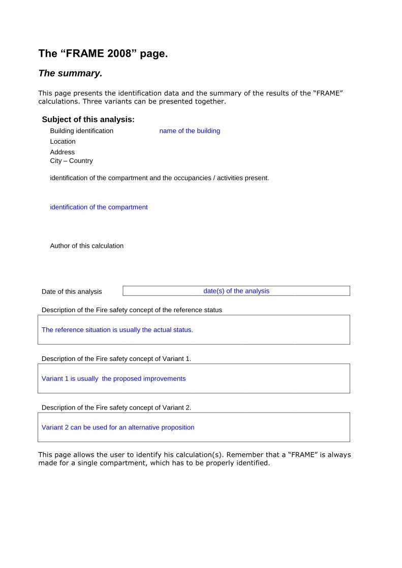
The “FRAME 2008” page.
The summary.
This page presents the identification data and the summary of the results of the “FRAME”
calculations. Three variants can be presented together.
Subject of this analysis:
Building identification name of the building
Location
Address
City – Country
identification of the compartment and the occupancies / activities present.
identification of the compartment
Author of this calculation
Date of this analysis date(s) of the analysis
Description of the Fire safety concept of the reference status
The reference situation is usually the actual status.
Description of the Fire safety concept of Variant 1.
Variant 1 is usually the proposed improvements
Description of the Fire safety concept of Variant 2.
Variant 2 can be used for an alternative proposition
This page allows the user to identify his calculation(s). Remember that a “FRAME” is always
made for a single compartment, which has to be properly identified.

Risk for: Reference Variant 1 Variant 2
Property R 0.57 0.34 0.34
Occupants R1 0.90 0.48 0.48
Activities R2 0.40 0.25 0.25
Potential risk
P 0.80 0.80 0.80
P1 1.71 1.71 1.71
P2 0.61 0.61 0.61
Acceptable risk
A 1.04 1.10 1.10
A1 1.18 1.23 1.23
A2 0.96 0.96 0.96
Protection Level
D 1.35 2.12 2.12
D1 1.61 2.90 2.90
D2 1.60 2.60 2.60
Fo 1.30
The spreadsheet is set up to present three variants.
The reference situation. This can be the as-is situation to make an assessment of an existing
situation before improvement, or it can also be a code-compliant concept for which an
alternative equivalent design is sought, or any other starting case.
Variants 1 and 2 can be used for a proposed improvement or alternative design, and the
description shall indicate what changes are made.
The values of the property, occupants and activities risk are coloured :
Green values indicate acceptable risk levels
Blue values indicate risk levels that may need improvement
Red values give unacceptable risk levels
A red bar indicates that abnormal values are obtained, e.g. negative values
Go to INFO Go to input
Go to input
Go to input
Go to INFO Go to input
Go to input
Go to input
Go to INFO Go to input
Go to input
Go to input

Calculation of the Orientation Value Ro, the initial risk.
An extra feature at the bottom of the Risk Assessment page, is the calculation of the initial risk
Ro for the reference case. This is an intermediate value to help the fire protection designer find
a recommended alternative to variant 1, based on the value of Ro.
The recommendation is automatically generated from the comparison between the calculated
value of Ro and the orientation table below.
Orientation Value Ro, Initial Risk 2.59
Proposed Fire protection concept, based on Ro
of “Reference” case : Install sprinklers
Ro limit Up to
0 1 Use manual fire protection
1 1.6 Add automatic fire detection
1.6 2.7 Install sprinklers
2.7 4.5 Sprinklers with improved water supplies
4.5 Too hazardous: reduce risk

The “Info P” page. This page gives information on the sub factors used in the Potential Risk calculations. The info
page shows the selection lists which can be used as entry data on the next calculation page.
Some cells have a pop-up comment added which gives extra information how to define that
particular item. (The pop-up comment is shown below in 8 pt characters).
The Potential risks P, P1, P2 are calculated with the fire load factor q, the spread factor i, the
area factor g, the level factor e, the venting factor v, and the access factor z.
Fire load factor q.
INFO for sub factors of Potential Risks
Fire load factor q
The fire load factor q is calculated with the fire load density of building elements and contents. It
indicates how much heat can be produced per unit area (m²). In theory, one must make a list of
all available combustible materials with their specific heat value, make a calculation of the total
possible heat release and divide this by the area of the compartment. In practice, the next tables
give reasonable estimates of the values of Qi and Qm (in MJ/m²) so that an exact calculation is
not always necessary.
Sub factor immobile fire load density Qi.
Immobile fire load density Qi
The ‘immobile’ fire load Qi comes from all combustible elements used for the construction such as the structure: beams, columns, girders, walls and partitions, windows, carpeting and decoration materials. In practice, building types can be classified in five groups with broadly the same fire loads. The following table gives the most relevant values.
A. Totally Incombustible ( e.g. concrete / steel only) 0
B. Incombustible construction, with max. 10% allowance
for combustible construction elements as windows, roof
covering, etc. 100
C1. Wooden structure finished with incombustible
materials. 300
C2. Masonry construction with wooden floors and girders 300
D. Incombustible structure, combustible finishing. 1000
E. Totally combustible construction 1500
This list pops-up at the P-page.
For compartments of mixed construction, it is recommended to use the highest estimate of Qi
for the whole compartment.

Sub factor mobile fire load density Qm.
The table with values of Qm gives an estimate of the mobile fire load density, based on several
surveys found in the technical literature, as well as by calculation based on the required sprinkler
water densities. The column “range” gives an overview of the data found. The user can correct
the average value of the table on the P-calculation sheet or enter a user-defined value based on
his observations, so that a more fitting value is used.
It is not necessary to have a sprinkler system to use this table: When the design criteria of an
adequate sprinkler system are known , the table gives a fair guess of the corresponding fire
load density.
Mobile (moveable) fire load density Qm Range
In theory, one must calculate with the total heat release of all materials of the content divided by the total floor area. In practice, the next table gives reasonable estimates.
User defined
a. Low fire hazard (LH or light hazard) occupancies 200
a1. Offices 400 80 - 550
a2. Dwellings 500 330 - 780
a3. Schools 200 215 - 340
a4. Hospitals 250 100 - 330
a5. Hotels 250 310 - 330
b. Ordinary fire hazard with low fire load (OH1 / NFPA: OH
Gp1) 600
c. Ordinary fire hazard with medium fire load (OH2 / NFPA
OH Gp2) 1500
d. Ordinary fire hazard with high fire load (OH3 / NFPA OH
Gp2+) 2000
e. Ordinary fire hazard with very high fire load (OH4) 2500
f. High hazard class HH1 2500
g. High hazard class HH2 (NFPA EH Gp1) 3000
h. High hazard class HH3 (NFPA EH Gp2) 3750
i. Rack storage For storage hazards, the fire load density is calculated with the total spray density needed for sprinklers. The fire load equals 300 MJ/m² per 1 l/min/m² sprinkler design density (or 0.1 gpm/sq.ft = 1250 MJ/m². For in-rack protection, add 3750 MJ/m² for each row of in rack sprinklers to the fire load density derived from the roof sprinklers density. 6750
j. Large drop sprinklers protected storage 7500
k. ESFR protected storage 7m high 12000
l. ESFR protected storage 5.5 bar 15000
Fire spread factor i.
The fire spread factor i indicates how easy a fire can spread through a building. It is calculated
from the average dimension of the content m, the flame propagation class M, and the destruction
temperature T.
Factor T is the temperature rise necessary to start the destruction of the content (or the building).
In this formula, T is expressed in centigrade (C), m in meter and M has no dimension. For the
factors M and T, a weighted average can be entered. There is a 100 % check added: the total
% will be in RED as long as it differs from 100 % (see below for factor M).
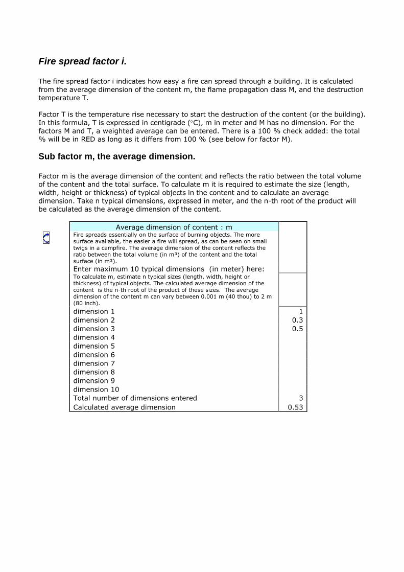
Sub factor m, the average dimension.
Factor m is the average dimension of the content and reflects the ratio between the total volume
of the content and the total surface. To calculate m it is required to estimate the size (length,
width, height or thickness) of typical objects in the content and to calculate an average
dimension. Take n typical dimensions, expressed in meter, and the n-th root of the product will
be calculated as the average dimension of the content.
Average dimension of content : m
Fire spreads essentially on the surface of burning objects. The more surface available, the easier a fire will spread, as can be seen on small twigs in a campfire. The average dimension of the content reflects the ratio between the total volume (in m³) of the content and the total surface (in m²).
Enter maximum 10 typical dimensions (in meter) here:
To calculate m, estimate n typical sizes (length, width, height or thickness) of typical objects. The calculated average dimension of the content is the n-th root of the product of these sizes. The average dimension of the content m can vary between 0.001 m (40 thou) to 2 m (80 inch).
dimension 1 1
dimension 2 0.3
dimension 3 0.5
dimension 4
dimension 5
dimension 6
dimension 7
dimension 8
dimension 9
dimension 10
Total number of dimensions entered 3
Calculated average dimension 0.53

Sub factor T, temperature rise.
T is the temperature necessary to start ignition or damage of the content. The following scale
gives an indication of the relevant values in °C.
Temperature rise T
Define the temperature necessary to start ignition or
damage of the content. The following scale gives an
indication of the relevant values in °C. Equivalent values in
°F are in brackets.
USER DEFINED INPUT 0 TOTAL:
WEIGHTED AVERAGE of the following classes: Any intermediate value is also acceptable. E.g. in a warehouse were packed and unpacked metal spare parts are stored, T= 250°C can be used. Be sure that the total of all classes is 100 %
234
100.00% This field becomes orange if not = 100%
a. Inflammable liquids ( 21°C - 70°F) 20 20.00%
b. Plastics, electronics, human beings (100°C - 212°F) Human beings only need to be considered as “ content” when they will remain for an extended time in the compartment during the fire growing phase. 100 0.00%
c. Textile, wood, paper, food (200°C - 400°F) 200 0.00%
d. Average content of residential buildings (250°C - 482°F) 250 60.00%
e. Machinery, household appliances (300°C - 572°F) 300 0.00%
f. Metal objects ( 400°C - 752°F) 400 20.00%
g. Non combustible (construction) materials (500°C - 932°F) 500 0.00%
Sub factor reaction to fire class M.
For the purpose of evaluation the speed of fire spread, 6 flame propagation or “reaction to fire”
classes, called M are used. It is important to notice that these classes apply for the surfaces. A
closed metal container with gasoline can be classified as M = 0, and a TV-set in a polystyrene box
will be classified M = 4 or even M = 5. For mixed contents, such as in warehouses, a weighed
average class e.g. M = 2.5 can also be used in the formula.
The table uses as reference classes the classifications that can be found in EN 13501-1 (reaction
to fire) and EN 12845 (sprinklers – packaging material categories)
Reaction to fire class M TOTAL:
WEIGHTED AVERAGE of the following classes. A weighted average is also acceptable. E.g. where unpacked and
expanded plastic protected metal spare parts are stored, a combination of A1 and F can be used. Be sure that the total is 100 %
2.5 90.00% This field
becomes orange if not
= 100%
A1 per EN13501-1 or Incombustible 0 40.00%
A2 per EN13501-1or Nearly incombustible 0.5 0.00%
B per EN13501 or EN12845 Cat. I : Difficult to ignite
(self extinguishing) 1 0.00%
C per EN13501-1 : Slow burning materials 2 0.00%
D per EN13501 or EN12845 Cat. II: Combustible surfaces 3 0.00%
E per EN13501-1 or EN12845 Cat. III Flammable surfaces 4 0.00%
F. EN12845 Cat. IV : Highly flammable surfaces 5 50.00%

The area factor g.
The area factor g indicates the horizontal influence of the fire. The factor g is calculated with
the values of l, the theoretical length of the compartment, and of b, the equivalent width,
expressed in meter. In order to define L and b it is very useful to have a scale drawing of the
compartment, especially when it is a building of an irregular shape.
The formula for g considers the size and the shape of the compartment. When a building is
only accessible from its narrow side (see below), the values of l and b are reversed to reflect
the increased difficulty for the fire brigade to control a fire in such a building.
Area factor g
Step 1: Define the longest distance between the centres of two sides of the
compartments' perimeter. This is the theoretical length l.
Step 2: Define the total surface area of the compartment : Atot
Step 3: Divide this area by the theoretical length to obtain the equivalent width b.
Step 4: Check if the building is accessible at its long side (left view): If NOT (right
view): use the " Narrow building" approach.
Building access for the fire brigade
Building accessible at its long side long
Building only accessible at its narrow side narrow

The level factor e:
Level factor e
Level number E, galleries, mezzanines, etc.
Number all the levels in the following way: E =0 for the main access level.
All upper levels are then E = 1,2,3, etc. All underground levels are then E= -
1, -2, -3, etc.
For galleries between levels, add the additional floor space as the decimal
part of the level number. When a first floor has a gallery of 40 % additional
floor space, enter the level number as 1.4.
The venting factor v:
Venting factor v
The venting factor v is calculated with the values of Qm, k
and h.
The mobile fire load is the most relevant measure for the potential heat release inside the building.
STEP 1: Define the height h, between the floor and the ceiling of the storey.
For a sloping roof or ceiling, it is the average height that is used. The
maximum value for h = 15 m. For higher ceilings, “FRAME” uses 15 m

STEP 2: Measure the total area of single glazed windows, glass and plastic
skylights in the ceiling (roof) and upper third of the walls opening to the
outside. Enter this area in m². When looking at the walls, one can broadly say that the openings in the lower third of the wall will allow fresh air to come in, the middle third will be a neutral zone, and the openings of the upper third will let the smoke out. Double-glazed windows, armoured glass and similar "strong" materials should not be considered as they take some time to break under the effects of the fire.
STEP 3 : Measure the aerodynamic area of natural smoke vents in m²
STEP 4: Define the capacity for the mechanical exhaust systems for smoke
extraction in Nm³/hour
OR define the ratio smoke exhaust openings / floor area
When the exact venting capacity is not known, a fair guess of that capacity can be made,
according to the quantity of light material present in the roof construction. E.g., when a roof is
made up of solid and transparent (plastic) sheet in a ratio of 1 transparent sheet for 19 solid
sheets, the light elements represent 5 % of the roof. Take 1/3 of this to estimate the venting
ratio at 1.5 % or k = 0.015. Do not guess values higher than 0.02 (2 % venting area).
The access factor z:
Access factor z
The access factor z indicates how difficult it is for outside help to get into the fire area and is calculated with b, H+ or H- and Z.
To define Z, the number of access directions, draw an imaginary map of the building with the north at the main entrance of the building, and check also the south, east and west for free access for the fire brigade. The number of accessible directions is Z (1 to 4).
Z
1
2
3
4
To define H+ or H- : Look at the fire brigades' way towards the fire up or down. When they
have to go upward, call H+ the vertical distance from the access level to the floor level of the
compartment. When they have to go downward, call H- the distance from access level to the
basement floor. The value of H is expressed in m
F.R.A.M.E.
20
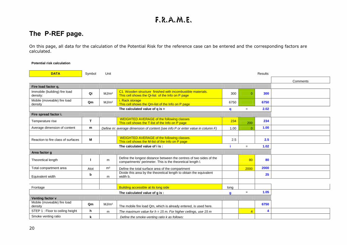
The P-REF page.
On this page, all data for the calculation of the Potential Risk for the reference case can be entered and the corresponding factors are
calculated.
Potential risk calculation
DATA Symbol Unit Results
Comments
Fire load factor q.
Immobile (building) fire load density:
Qi MJ/m² C1. Wooden structure finished with incombustible materials. This cell shows the Qi-list of the Info on P page
300 0 300
Mobile (moveable) fire load density
Qm MJ/m² i. Rack storage This cell shows the Qm-list of the Info on P page
6750 6750
The calculated value of q is = q = 2.02
Fire spread factor i.
Temperature rise T
WEIGHTED AVERAGE of the following classes This cell shows the T-list of the Info on P page
234 200
234
Average dimension of content m Define m: average dimension of content (see info P or enter value in column F) 1.00 0 1.00
Reaction to fire class of surfaces M
WEIGHTED AVERAGE of the following classes. This cell shows the M-list of the Info on P page
2.5
2.5
The calculated value of i is : i = 1.02
Area factor g
Theoretical length l m Define the longest distance between the centres of two sides of the compartments' perimeter. This is the theoretical length l.
80 80
Total compartment area Atot m² Define the total surface area of the compartment 2000 2000
Equivalent width b
m Divide this area by the theoretical length to obtain the equivalent width b.
25
Frontage Building accessible at its long side long
The calculated value of g is : g = 1.05
Venting factor v
Mobile (moveable) fire load density
Qm MJ/m² The mobile fire load Qm, which is already entered, is used here.
6750
STEP 1 : Floor to ceiling height h m The maximum value for h = 15 m. For higher ceilings, use 15 m 4 4
Smoke venting ratio k Define the smoke-venting ratio k as follows:

F.R.A.M.E.
21
STEP 2 m² Total area of single glazed windows, glass and plastic skylights in the ceiling (roof) and upper third op the walls giving to the outside.
10 3
STEP 3 m² Measure the aerodynamic area of static smoke vents in m² 10 10
Nm³/h Nominal flow of mechanical (smoke) ventilation systems 0
m² Total area of compartment 2000 0.01
The smoke venting ratio k (calculated with these values) or estimated k = 3% 0.03
The calculated value of v is: v = 0.98
Level factor e
Level E Mezzanines and platforms : add decimal value to level number 0 0
The calculated value of e is: e = 1.00
Access factor z
The number of access directions Z The number of accessible directions is Z (1 to 4). 4 4
Height difference H m Height difference in meter (positive or negative) 3 -3
b already entered for factor g 25
Access factor z z = 1.05
Potential Risks
Potential risk values for :
Fire load factor q. q 2.02 property (building and content) P 2.20
Fire spread factor i. i 1.02 occupants (people) P1 2.10
Area factor g g 1.05 activities P2 1.09
Level factor e e 1.00
Venting factor v v 0.98
Access factor z z 1.05
Clicking on the yellow cells shows the lists of suggested values from the Info on P page, of which one can be selected , or the measured
value has to be entered. In the green cells, the suggested value can be corrected. When weighed averages are used, they shall be defined
first on the info Page.
F.R.A.M.E.
22
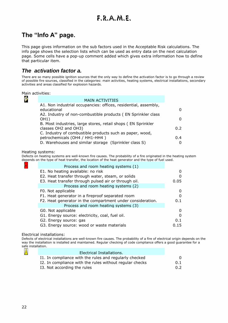
The “Info A” page.
This page gives information on the sub factors used in the Acceptable Risk calculations. The
info page shows the selection lists which can be used as entry data on the next calculation
page. Some cells have a pop-up comment added which gives extra information how to define
that particular item.
The activation factor a. There are so many possible ignition sources that the only way to define the activation factor is to go through a review of possible fire sources, classified in the categories: main activities, heating systems, electrical installations, secondary activities and areas classified for explosion hazards.
Main activities:
MAIN ACTIVITIES
A1. Non industrial occupancies: offices, residential, assembly,
educational 0
A2. Industry of non-combustible products ( EN Sprinkler class
OH1) 0
B. Most industries, large stores, retail shops ( EN Sprinkler
classes OH2 and OH3) 0.2
C. Industry of combustible products such as paper, wood,
petrochemicals (OH4 / HH1-HH4 ) 0.4
D. Warehouses and similar storage (Sprinkler class S) 0
Heating systems: Defects on heating systems are well-known fire causes. The probability of a fire originated in the heating system depends on the type of heat transfer, the location of the heat generator and the type of fuel used.
Process and room heating systems (1)
E1. No heating available: no risk 0
E2. Heat transfer through water, steam, or solids 0
E3. Heat transfer through pulsed air or through oil. 0.05
Process and room heating systems (2)
F0. Not applicable 0
F1. Heat generator in a fireproof separated room 0
F2. Heat generator in the compartment under consideration. 0.1
Process and room heating systems (3)
G0. Not applicable 0
G1. Energy source: electricity, coal, fuel oil. 0
G2. Energy source: gas 0.1
G3. Energy source: wood or waste materials 0.15
Electrical installations: Defects of electrical installations are well-known fire causes. The probability of a fire of electrical origin depends on the way the installation is installed and maintained. Regular checking of code compliance offers a good guarantee for a safe installation.
Electrical Installations.
I1. In compliance with the rules and regularly checked 0
I2. In compliance with the rules without regular checks 0.1
I3. Not according the rules 0.2

F.R.A.M.E.
23
Explosion risks: The presence or occasional escape of flammable vapours, gases or dusts is an additional source of fire.
Explosion risks (1)
Z. Not applicable 0
Z0. Permanent explosion risk ATEX zone 0 0.3
Z1. Explosion risk under normal conditions ATEX zone 1, NEC:
Class I Div.1 0.2
Z2. Occasional explosion risk ATEX Zone 2 NEC: CLASS I
DIV.2 area 0.1
Explosion risks. (2)
K0. Not applicable 0
K1. Dust explosion hazard ATEX zones 20/21/22 NEC : Class
II area 0.2
K2. Production of combustible dusts without extraction 0.1
Painting, spraying or coating with flammable products; use of
solvents and flammable glues, etc.
NONE 0
N1. In a separated, well ventilated room 0.05
N2. In a separated space without additional ventilation 0.1
N3. Without separation 0.2
Secondary activities: Secondary activities are only taken into account when they create an additional number of fire sources, compared with the main activities. Welding e.g. will not be aggravating in a metalwork shop but must be taken into account in a carpentry shop.
The evacuation time factor t
Evacuation time factor t
The evacuation time factor is calculated with the number of
persons present in the compartment, their mobility, the
dimensions of the building and the characteristics of the exit
ways.
The total length of the evacuation path is calculated with the
values of b, l, H+ or H-, which were already given.
INFO about X
Define X, the number of persons that can be present in the
compartment. X is total number of persons that will have to evacuate the
compartment.
If this number is unknown, use the next table with occupant
load factors based on NFPA 101. Be careful: local code
requirements may use different occupant load factors.
User defined total number of persons in the compartment
01. Waiting spaces 3
02. Places of assembly, concentrated use (halls, churches,
dancing) 1.5
03. Places of assembly, normal use (conference rooms,
restaurants, cafés) 0.6
04. Classrooms in schools, no fixed seating 0.5
05. Day nurseries 0.3
06. Schools: laboratories, shops and vocational rooms 0.2
07. Medical institutions 0.1
08. Jails, detention houses 0.1
09. Residential buildings (houses, hotels, guest houses) 0.05

F.R.A.M.E.
24
10. Sales area on street access floor, below street access floor 0.3
11. Sales area on floors above access floor 0.2
12. Offices 0.1
13. Factories 0.03
14. Storage and warehouses 0.003
15. LOCAL CODE DEFINED OCCUPANT LOAD FACTOR 0.2
INFO about x
Define x, by counting all the exit units of the compartment
according to legal and practical rules.
x is the number of exit units. The minimal width for an exit is
0.6 m (or 2 ft) unless law or practical conditions specify it
otherwise. E.g. in a hospital, it is clear that the minimal width is that of the
beds which are used in the hospital.
Consider some 20 cm (8 in) of lost width, i.e. a 80 cm (32 in)
wide door has an effective width of 60 cm (24 in). A 2 m wide
(80 in) corridor has an effective width of 1.80 m (72 in).
To define the value of x, look for each exit at the narrowest
passage on the path, measure the width in cm or inches,
deduct 20 cm or 8 in and divide the result by 60 cm or 24 in.
This will give the number of exit units per exit path. The sum
of all the quotients gives the total number of exit units of the
compartment.
In the example, the width of door A is relevant for exit path A,
but for B it is the width C of the corridor.
Remark: large gates, sliding doors (except where specifically
designed for emergency exit) and roller shutters shall not be
considered as exit units!
INFO about p %
Persons that can move independently and are accustomed to
the building features will be able to evacuate rapidly. People
who need help or have to find their way to the exits will need
more time. Factor p corrects the evacuation time for the lack of mobility of the occupants and for other unfavourable circumstances..
Possibility D permits the calculation of a p factor for a mixed
group
A. Mobile and independent persons ( adults, workers) 1
10.00
%
B. Mobile persons needing guidance ( pupils, visitors) 2
20.00
%
C. Persons with limited mobility (patients, elderly, inmates) Such as patients or elderly, handicapped or sleeping persons (in hotels)... 8
70.00
%
D. Calculated value for mixed group 6.1 check:
100.0
0%

F.R.A.M.E.
25
INFO about K - Available and distinct exit paths
The number of AVAILABLE and DISTINCT exit paths is
calculated in the following way:
First, enter the number of exits that end in the open air,
basically external doors and exterior stairways , but no
ladders.
The second step is to define the maximum capacity of all the
exits together. This is done (automatically) by multiplying the
number of exit units by 120. The maximum capacity of an exit unit having a useful width of 60 cm ( e.g. a door of 80 cm ) is 120 persons per minute. If more people try to use this exit, they will be queuing to pass, which slows down the exit movement.
The third step is to divide this capacity by the number of
occupants that are present. This quotient is the theoretical
number of "distinct" exit paths. The real number of distinct
exit paths shall be not more than 4 (implying a 90° angle
between them). When all the exit units are needed to satisfy the evacuation requirements for the occupants , they shall be considered as a SINGLE useful exit path.
The number of the AVAILABLE and DISTINCT exit paths "K" is
then the smallest value found in steps 1 and 3 .
value
of K
Less than 1:
Not
allowed
more than 1 and less than 2: 1
more than 2 and less than 3: 2
more than 3 and less than 4: 3
more than 4: 4
The content factor c. Factor c defines the value of the contents of the compartment. It is calculated from is monetary value and replacement possibilities.
relative value of the content c1
Choose the value of c1 according to the possibility to replace
the contents:
a. the contents can be easily replaced 0
b. the contents can difficulty be replaced 0.1
c. the contents are unique. 0.2
The property value V .
'Property' means as well the compartment itself as the goods in it, as its occupants.
F.R.A.M.E.
26
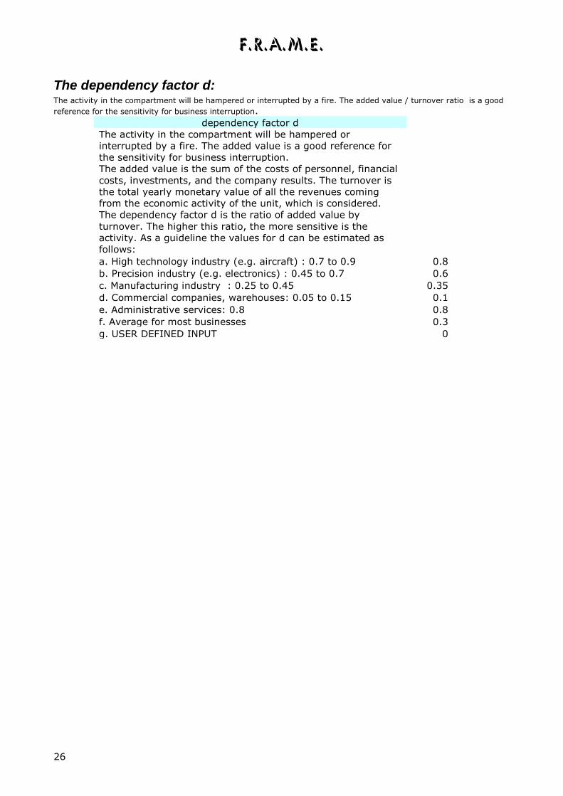
The dependency factor d: The activity in the compartment will be hampered or interrupted by a fire. The added value / turnover ratio is a good
reference for the sensitivity for business interruption.
dependency factor d
The activity in the compartment will be hampered or
interrupted by a fire. The added value is a good reference for
the sensitivity for business interruption.
The added value is the sum of the costs of personnel, financial
costs, investments, and the company results. The turnover is
the total yearly monetary value of all the revenues coming
from the economic activity of the unit, which is considered.
The dependency factor d is the ratio of added value by
turnover. The higher this ratio, the more sensitive is the
activity. As a guideline the values for d can be estimated as
follows:
a. High technology industry (e.g. aircraft) : 0.7 to 0.9 0.8
b. Precision industry (e.g. electronics) : 0.45 to 0.7 0.6
c. Manufacturing industry : 0.25 to 0.45 0.35
d. Commercial companies, warehouses: 0.05 to 0.15 0.1
e. Administrative services: 0.8 0.8
f. Average for most businesses 0.3
g. USER DEFINED INPUT 0
F.R.A.M.E.
27
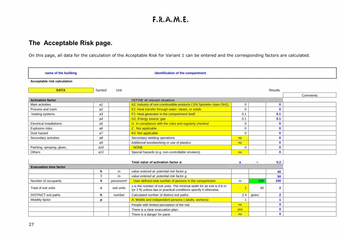
The Acceptable Risk page.
On this page, all data for the calculation of the Acceptable Risk for Variant 1 can be entered and the corresponding factors are calculated.
name of the building identification of the compartment
Acceptable risk calculation
DATA Symbol Unit Results
Comments
Activation factor DEFINE all relevant situations
Main activities a1 A2. Industry of non-combustible products ( EN Sprinkler class OH1) 0 0
Process and room a2 E2. Heat transfer through water, steam, or solids 0 0
heating systems a3 F2. Heat generator in the compartment itself. 0.1 0.1
a4 G2. Energy source: gas 0.1 0.1
Electrical Installations. a5 I1. In compliance with the rules and regularly checked 0 0
Explosion risks. a6 Z. Not applicable 0 0
Dust hazard a7 K0. Not applicable 0 0
Secondary activities a8 Secondary welding operations no 0
a9 Additional woodworking or use of plastics no 0
Painting, spraying, glues, a10 NONE 0 0
Others a11 Special hazards (e.g. non-controllable smokers) no 0
Total value of activation factor a: a = 0.2
Evacuation time factor
b m value entered at: potential risk factor g 40
l m value entered at: potential risk factor g 50
Number of occupants X persons/m² User defined total number of persons in the compartment m 100 100
Total of exit units x exit units x is the number of exit units. The minimal width for an exit is 0.6 m (or 2 ft) unless law or practical conditions specify it otherwise.
2 50 2
DISTINCT exit paths K number Calculated number of distinct exit paths:. 2.4 gives: 2
Mobility factor p A. Mobile and independent persons ( adults, workers) 1 1
People with limited perception of the risk no 0
There is a clear evacuation plan: yes 0
There is a danger for panic no 0

F.R.A.M.E.
28
Equivalent length of vertical travelling path based on H+ or H- value entered at potential risk factor z 1.25 0 0
Evacuation time factor t = 0.08
Content factor
Relative value c1 b. the content can difficulty be replaced 0.1 0.1
Absolute value of content Actual value in million of CURRENCY (e.g. EUR, GBP, USD, SWF... ) 13.0 million EUR
Building cost index National building cost index at the time of the risk assessment 654
Correction for inflation National building cost index in 2000 503 in 2000: 10.00
Exchange rate EUR 1 CURRENCY = x.yz EURO 1.00 in EURO
Reference value Value in EURO , at given exchange rate and corrected for inflation 10.00
Content value factor c2 0.04
Content factor c = 0.14
Environment factor
Qi value entered at potential risk factor q 100
M value entered at potential risk factor i 1
Environment factor r = 0.30
Dependency factor
Added value /turnover ratio d f. Average for most businesses 0.3 0 0.3
Dependency factor d = 0.3
Acceptable Risks
Acceptable risk values for :
Activation factor a 0.20 property (building and content) = 1.6 - a - t - c A 1.19
Evacuation time factor t 0.08 occupants (people) = 1.6 - a - t - r A1 1.02
Content factor c 0.14 activities = 1.6 - a - c - d A2 0.96
Environment factor r 0.30 WARNING :If the value of A or A1 or A2 is lower than 0.2 or even negative,
Dependency factor d 0.30 an unacceptable risk situation exists ! CHANGE first a, t, c, r or d
F.R.A.M.E.
29
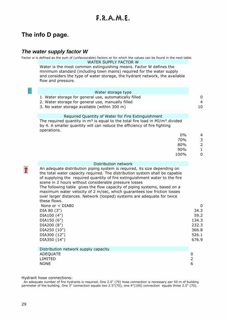
The info D page.
The water supply factor W Factor w is defined as the sum of (unfavourable) factors wi for which the values can be found in the next table.
WATER SUPPLY FACTOR W
Water is the most common extinguishing means. Factor W defines the
minimum standard (including town mains) required for the water supply
and considers the type of water storage, the hydrant network, the available
flow and pressure.
Water storage type
1. Water storage for general use, automatically filled 0
2. Water storage for general use, manually filled 4
3. No water storage available (within 300 m) 10
Required Quantity of Water for Fire Extinguishment
The required quantity in m³ is equal to the total fire load in MJ/m² divided
by 4. A smaller quantity will can reduce the efficiency of fire fighting
operations.
0% 4
70% 3
80% 2
90% 1
100% 0
Distribution network
An adequate distribution piping system is required, its size depending on
the total water capacity required. The distribution system shall be capable
of supplying the required quantity of fire extinguishment water to the fire
scene in 2 hours without considerable pressure losses
The following table gives the flow capacity of piping systems, based on a
maximum water velocity of 2 m/sec, which guarantees low friction losses
over larger distances. Network (looped) systems are adequate for twice
these flows.
None or < DIA80 0
DIA 80 (3") 34.3
DIA100 (4") 59.2
DIA150 (6") 134.3
DIA200 (8") 232.3
DIA250 (10") 366.8
DIA300 (12") 526.1
DIA350 (14") 676.9
Distribution network supply capacity
ADEQUATE 0
LIMITED 2
NONE 6
Hydrant hose connections: An adequate number of fire hydrants is required. One 2.5" (70) hose connection is necessary per 50 m of building perimeter of the building. One 3" connection equals two 2.5"(70); one 4"(100) connection equals three 2.5" (70).
F.R.A.M.E.
30
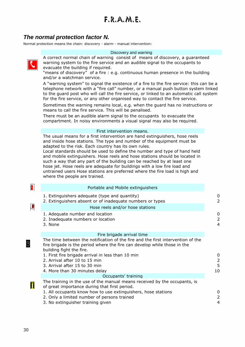
The normal protection factor N. Normal protection means the chain: discovery - alarm - manual intervention:
Discovery and warning
A correct normal chain of warning consist of means of discovery, a guaranteed
warning system to the fire service and an audible signal to the occupants to
evacuate the building if required.
“means of discovery” of a fire : e.g. continuous human presence in the building
and/or a watchman service.
A “warning system” to signal the existence of a fire to the fire service: this can be a
telephone network with a “fire call” number, or a manual push button system linked
to the guard post who will call the fire service, or linked to an automatic call system
for the fire service, or any other organised way to contact the fire service.
Sometimes the warning remains local, e.g. when the guard has no instructions or
means to call the fire service. This will be penalised.
There must be an audible alarm signal to the occupants to evacuate the
compartment. In noisy environments a visual signal may also be required.
First intervention means.
The usual means for a first intervention are hand extinguishers, hose reels
and inside hose stations. The type and number of the equipment must be
adapted to the risk. Each country has its own rules.
Local standards should be used to define the number and type of hand held
and mobile extinguishers. Hose reels and hose stations should be located in
such a way that any part of the building can be reached by at least one
hose jet. Hose reels are adequate for buildings with a low fire load and
untrained users Hose stations are preferred where the fire load is high and
where the people are trained.
Portable and Mobile extinguishers
1. Extinguishers adequate (type and quantity) 0
2. Extinguishers absent or of inadequate numbers or types 2
Hose reels and/or hose stations
1. Adequate number and location 0
2. Inadequate numbers or location 2
3. None 4
Fire brigade arrival time
The time between the notification of the fire and the first intervention of the
fire brigade is the period where the fire can develop while those in the
building fight the fire.
1. First fire brigade arrival in less than 10 min 0
2. Arrival after 10 to 15 min 2
3. Arrival after 15 to 30 min 5
4. More than 30 minutes delay 10
Occupants' training
The training in the use of the manual means received by the occupants, is
of great importance during that first period.
1. All occupants know how to use extinguishers, hose stations 0
2. Only a limited number of persons trained 2
3. No extinguisher training given 4

F.R.A.M.E.
31
The special protection factor S
SPECIAL PROTECTION FACTOR S
Under special protection the following are considered: automatic fire
detection, improved water supplies, automatic fire protection systems, well
equipped fire brigades.
Automatic detection
Automatic detection systems speed up the discovery of a fire and the fire
brigade intervention. They can only be considered if there is a guaranteed
connection to the fire brigade, which will immediately react to the signal.
Sprinkler systems connected to a fire alarm by flow switches can be
considered as slow thermal detection systems. Smoke and flame detectors
will be considered as fast detectors. Electronic supervision of the system
and individual identification of a small fire zone (e.g. per detector) will give
extra bonuses.
None 0
1. Automatic detection by sprinklers + flow or pressure switch 4
2. by thermal (heat) detectors 5
3. by smoke or flame detectors 8
4. by smoke alarm units 2
Improved water supplies
The water supplies are of prime importance for fire fighting. Rivers, lakes and any other water storage that can guarantee 4 or more times the quantity of water needed are considered as inexhaustible. The water has to be conveyed to the fire scene by a flow/pressure source with a reliable energy source : a water tower, pump, elevated reservoir..
Single flow/pressure source 0
Highly reliable : One water storage with a double flow/pressure source 5
Duplicated highly reliable: two storages, each with a flow/pressure source 12
Automatic protection for the compartment.
Consider at this point only automatic protection systems that cover the
entire compartment. Partial systems for critical items are taken into account
with factor Y.
None 0
1. Sprinklers with one (public) water supply 11
2. Sprinklers with one independent water supply 14
3. Sprinklers with two independent water supplies 20
Sprinkler systems can only be considered as automatic protection when they are adequate for the
occupancy and have at least one adequate water supply.
Responding fire station
1. Full time station 24h/24 7d/7 8
2. Professional crewed station ( day time crewed, night time retained ) 6
3. Retained station (part time professionals) 4
4. Volunteer crewed station 2
Industrial private fire brigade
None 0
1. Part time industrial fire brigade (working hours) 6
2. Full time industrial fire brigade 24h/24 14
Temporary private fire brigades are only fully staffed during working hours. Permanent private
fire brigades are staffed "around the clock". This type of private fire brigades is normally only
organised at large industrial sites.

F.R.A.M.E.
32
The fire resistance factor F
FIRE RESISTANCE FACTOR F
The fire resistance factor F is defined by the fire resistance of the building
elements, but with a correction for the value of the special protection S.
Such correction is necessary as the presence of active fire protection
systems reduces somewhat the benefit of passive protection.
The average fire resistance is calculated with the fire resistance in minutes
of the structure, the outside walls, the roof or ceiling, and the inner walls.
In most countries, the fire rating of construction elements will be expressed
in minutes as defined by tests based on the ISO R 834 time/temperature
curve.
For structural building elements the main criterion is stability, although
other requirements such as thermal insulation, smoke- and flame tightness
and other features are also in use for certification.
“FRAME” considers stability only for load bearing elements such as columns,
beams, floors and roofs.
For partitions (subcompartmentation) flame tightness and insulation are
required.
The following limitations also apply
1. To avoid unrealistic high values, do not use fire ratings higher than 120
minutes.
2. Do not use higher values for outside walls, roof or ceiling and inner walls
than for the structure.
3. For mixed construction elements, use the rating of the weakest part.
4. Windows in outside walls can be neglected if they cover less than 5 % of
the wall area.
5. The rating of roofs and ceilings is mainly defined by the underside.
6. For buildings with sprinklers designed to protect the structure or the roof,
the duration of the water supply can be taken as the fire rating, but not for
more than 60 minutes.
7. Consider only interior walls which subdivide the compartment in fire
areas, none of them should be more than 25 % of the compartment, and no
area should be larger than 1000 m²

F.R.A.M.E.
33
The escape factor U and the salvage factor Y:
ESCAPE FACTOR U
The escape factor U takes into account all elements of the special protection
that decrease the evacuation time or reduce the development of the fire.
Additional compartmentation and protection of the exit paths are also
evaluated.
Automatic detection systems speed up the discovery of a fire and the
evacuation. The same values apply as for factor S, the special protection.
Compartmentation and exit path protection will reduce smoke and heat
spread. Shortening the exit paths and good signage will allow the occupants
to move faster into a safe area.
Automatic fire detection systems
Compartment wide fire detection systems, which are already entered for the
special protection factor S are automatically taken into account for the
calculation of the escape factor U.
Partial fire detection in critical areas, e.g. in escape routes or increased
hazard rooms can be considered here. A small bonus is given , when less
than 300 persons have to be evacuated.
Subcompartments
None 0
1. EI30 Subcompartments (fire areas of max.1000 m²) 2
2. EI60 Subcompartments (fire areas of max.1000 m²) 4
Type of stairways for evacuation
No stairs used for exit 0
1. Open inside stairs 0
2. Single enclosed inside stair 1
3. More than one enclosed inside stair 2
4. At least one enclosed and smoke protected inside stair 3
5. More than one enclosed and smoke protected inside stair 4
6. Inside stair(s) and 1 outside stair 6
7. Inside stair(s) and more than 1 outside stair 8
8. Inside stair and outside toboggan or ladders for 1st / 2nd floor 2
Horizontal exits
No horizontal exits 0
1. Horizontal exit to adjacent compartment min. 50% of required capacity 2
2. Horizontal exit(s) to adjacent compartment(s) 100% of required capacity 8
Sprinkler protection
None 0
1. Sprinklers only in areas with increased fire risk 5
2. Whole compartment protected by sprinklers 10
SALVAGE FACTOR Y
The salvage factor Y evaluates those physical provisions that protect
sensitive parts of the activity against the impact of a fire, and organisational
measures to assure a swift restart of the activities if necessary on an other
location.
F.R.A.M.E.
34
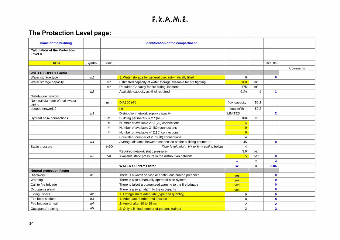
The Protection Level page:
name of the building identification of the compartment
Calculation of the Protection Level D
DATA Symbol Unit Results
Comments
WATER SUPPLY Factor
Water storage type w1 1. Water storage for general use, automatically filled 0 0
Water storage capacity m³ Estimated capacity of water storage available for fire fighting 160 m³
m³ Required Capacity for fire extinguishment 175 m³
w2 Available capacity as % of required 91% 1 1
Distribution network
Nominal diameter of main water piping
mm DIA100 (4") flow capacity 59.2
Looped network ? no total m³/h 59.2
w3 Distribution network supply capacity LIMITED 2
Hydrant hose connections m Building perimeter ( = 2 * (b+l)) 180 m
# Number of available 2.5" (70) connections 4
# Number of available 3" (80) connections 0
# Number of available 4" (110) connections 0
Equivalent number of 2.5" (70) connections 4
w4 Average distance between connection on the building perimeter 45 0
Static pressure m H2O Floor level height H+ or H- + ceiling height 4
Required network static pressure 3.9 bar
w5 bar Available static pressure in the distribution network 5 bar 0
w = 3
WATER SUPPLY Factor W = 0.86
Normal protection Factor
Discovery n1 There is a watch service or continuous human presence yes 0
Warning There is also a manually operated alert system yes 0
Call to fire brigade There is (also) a guaranteed warning to the fire brigade yes 0
Occupants alarm There is also an alarm to the occupants yes 0
Extinguishers n2 1. Extinguishers adequate (type and quantity) 0 0
Fire hose stations n3 1. Adequate number and location 0 0
Fire brigade arrival n4 2. Arrival after 10 to 15 min 2 2
Occupants' training n5 2. Only a limited number of persons trained 2 2
F.R.A.M.E.
35
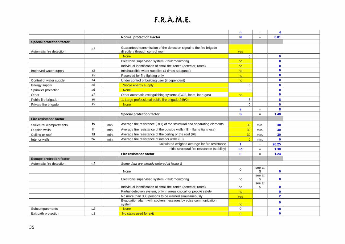
n = 4
Normal protection Factor N = 0.81
Special protection factor
Automatic fire detection s1
Guaranteed transmission of the detection signal to the fire brigade directly / through control room yes
None 0 0
Electronic supervised system - fault monitoring no 0
Individual identification of small fire zones (detector, room) no 0
Improved water supply s2 Inexhaustible water supplies (4 times adequate) no 0
s3 Reserved for fire fighting only no 0
Control of water supply s4 Under control of building user (independent) no 0
Energy supply s5 Single energy supply 0 0
Sprinkler protection s6 None 0 0
Other s7 Other automatic extinguishing systems (CO2, foam, inert gas) no 0
Public fire brigade s8 1. Large professional public fire brigade 24h/24 8 8
Private fire brigade s9 None 0 0
s = 8
Special protection factor S = 1.48
Fire resistance factor
Structural /compartments fs min. Average fire resistance (REI) of the structural and separating elements: 30 min. 30
Outside walls ff min. Average fire resistance of the outside walls ( E = flame tightness) 30 min. 30
Ceiling or roof fd min. Average fire resistance of the ceiling or the roof (RE) 30 min. 30
Interior walls fw min. Average fire resistance of interior walls (EI) 0 min. 0
Calculated weighed average for fire resistance f = 26.25
Initial structural fire resistance (stability) Fo = 1.30
Fire resistance factor F = 1.24
Escape protection factor
Automatic fire detection u1 Some data are already entered at factor S
None
0 see at
S 0
Electronic supervised system - fault monitoring no
see at S 0
Individual identification of small fire zones (detector, room) no
see at S 0
Partial detection system, only in areas critical for people safety no 0
No more than 300 persons to be warned simultaneously yes 2
Evacuation alarm with spoken messages by voice communication system no
0
Subcompartments u2 None 0 0
Exit path protection u3 No stairs used for exit 0 0

F.R.A.M.E.
36
Horizontal exits No horizontal exits 0 0
Signage and illumination Exit paths completely marked and illuminated yes 4
Sprinklers? u4 None 0 0
Other automatic system u5 Other automatic extinguishing systems (CO2, foam, inert gas) no see at
S 0
Smoke vents actuation u6 Smoke venting actuated by automatic detection no 0
Public fire brigade u7 1. Large professional public fire brigade 24h/24 8 see at
S 8
Private fire brigade u8 None 0
see at S
0
u = 14
Escape protection factor U = 1.98
Salvage factor
Compartmentation yi None 0 0
PHYSICAL PROTECTION
Detection yi Partial detection system, only in areas critical for business continuity no 0
Sprinkler Local sprinkler protection for critical equipment no 0
Other systems yi Other LOCAL automatic extinguishing systems (CO2, foam, inert gas) no 0
ORGANISATION
FINANCIAL yi Safeguarded financial and economical data yes 2
EQUIPMENT yi Easy access to spare parts and replacements yes 4
REPAIRS yi Repairs possible with minimal help yes 2
RELOCATION Immediate transfer of activities possible no 0
COOPERATION yi Written agreements for relocation exist no 0
PRODUCTION CENTRES yi Production capacity available at more than one location no 0
y = 8
Salvage factor Y = 1.48
Protection levels D
Protection levels for:
WATER SUPPLY Factor W 0.86 Property D 1.28
Normal protection Factor N 0.81 Occupants D1 1.61
Special protection factor S 1.48 Activities D2 1.52
Fire resistance factor F 1.24
Escape protection factor U 1.98
Salvage factor Y 1.48

F.R.A.M.E.
37
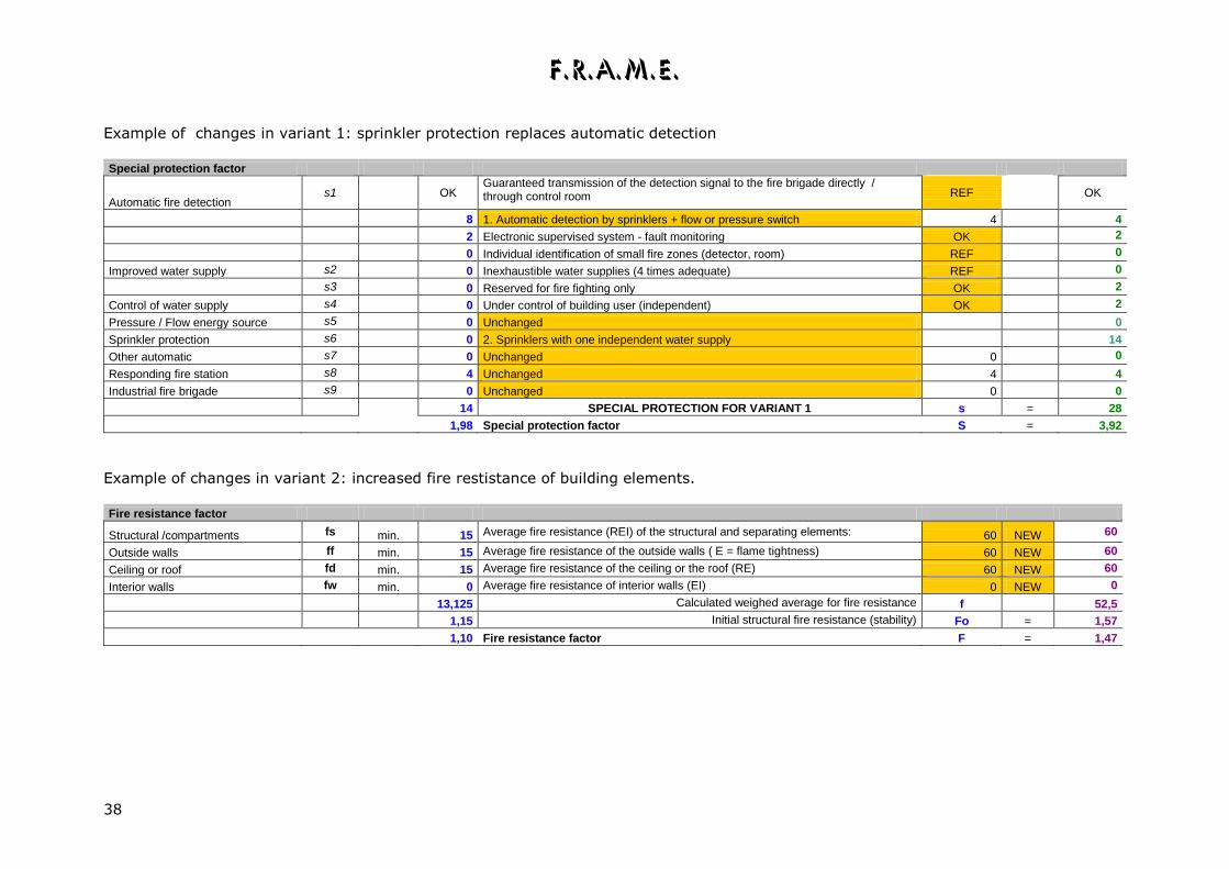
The P- V1, A- V1, D- V1, P- V2, A- V2 and D- V2 pages.
These pages give in the first columns the values obtained for the reference case and the possibility to modify the data. At the start, most
data fields will show “Unchanged” or “REF” , and the data of the reference case are simply used for the vriants as well. You can modify
the data for Variants 1 and 2 and the changes will be immediately used in the variants’ calculation.
Potential risk calculation Variant 1 describes usually the proposed improvements, eg. sprinklers instead of automatic fire detection
DATA Symbol P - REF
DATA VARIANT 1 NEW VALUES VARIANT 1
Fire load factor q.
Immobile (building) fire load density:
Qi MJ/m² 100 Unchanged 100 0 100
Mobile (moveable) fire load density Qm MJ/m² 500 Unchanged 500 0 500
1,30 The calculated value of q is = q = 1,30
DATA Symbol Unit A - REF
DATA VARIANT 1 NEW VALUES VARIANT 1
Activation factor DEFINE all relevant situations
Main activities a1 0,00 Unchanged 0,00 0,00
Process and room a2 0,00 Unchanged 0,00 0,00
heating systems a3 0,00 Unchanged 0,00 0,00
a4 0,10 Unchanged 0,10 0,10
Electrical Installations. a5 0,00 Unchanged 0,00 0,00
Explosion risks. a6 0,00 Unchanged 0,00 0,00
Dust hazard a7 0,00 Unchanged 0,00 0,00
Secondary activities a8 0,00 NO secondary welding operations REF 0,00
a9 0,00 NO additional woodworking or use of plastics REF 0,00
F.R.A.M.E.
38
Example of changes in variant 1: sprinkler protection replaces automatic detection
Special protection factor
Automatic fire detection s1
OK
Guaranteed transmission of the detection signal to the fire brigade directly / through control room REF
OK
8 1. Automatic detection by sprinklers + flow or pressure switch 4 4
2 Electronic supervised system - fault monitoring OK 2
0 Individual identification of small fire zones (detector, room) REF 0
Improved water supply s2 0 Inexhaustible water supplies (4 times adequate) REF 0
s3 0 Reserved for fire fighting only OK 2
Control of water supply s4 0 Under control of building user (independent) OK 2
Pressure / Flow energy source s5 0 Unchanged 0
Sprinkler protection s6 0 2. Sprinklers with one independent water supply 14
Other automatic s7 0 Unchanged 0 0
Responding fire station s8 4 Unchanged 4 4
Industrial fire brigade s9 0 Unchanged 0 0
14 SPECIAL PROTECTION FOR VARIANT 1 s = 28
1,98 Special protection factor S = 3,92
Example of changes in variant 2: increased fire restistance of building elements.
Fire resistance factor
Structural /compartments fs min. 15 Average fire resistance (REI) of the structural and separating elements: 60 NEW 60
Outside walls ff min. 15 Average fire resistance of the outside walls ( E = flame tightness) 60 NEW 60
Ceiling or roof fd min. 15 Average fire resistance of the ceiling or the roof (RE) 60 NEW 60
Interior walls fw min. 0 Average fire resistance of interior walls (EI) 0 NEW 0
13,125 Calculated weighed average for fire resistance f 52,5
1,15 Initial structural fire resistance (stability) Fo = 1,57
1,10 Fire resistance factor F = 1,47

F.R.A.M.E.
39
Special compartment types.
Atrium compartments. Using FRAME for risk evaluation for atriums and compartments with more than one floor
requires some explanation to obtain a correct result. One must always take care to use the
most relevant value for the formulas.
Basically, additional floor area for mezzanines and partial levels will be considered in the level
factor e, as a percentage of the ground floor area, but other factors are also modified in an
atrium.
Fire load factor q.
The immobile fire load Qi has to include all combustible construction elements: if the
mezzanines are built on a wooden structure, this has to be included in Qi.
For the mobile fire load Qm, one must check if the goods on the mezzanine are protected from
fire spread from the level below, e.g. by a concrete floor.
Basically the fire load on every level can be seen as separate, and the highest value will be
used in the formula. But when the fire load is located on a grating floor, in which case fire
spread is likely , it is better to add the fire load of the floors to calculate Qm, but in that case
the area of the grating floor does not count anymore for the level factor e.
Area factor g
To evaluate the compartmentation, the basis is that a complete level of a building is
compartment. When in a building, e.g. an apartment building, subcompartmentation exists
between the individual flats, on the same floor and using the same access and evacuation
paths, it is necessary to consider the whole floor as a single compartment, otherwise
unrealistic low values will be found for factors g and t. The subcompartmentation is taken into
account in the factors F and U
However, in the case that a floor is subdivided in two or more compartments, so that
evacuation is possible to an adjacent compartment as "safe area" , each part of the floor can
considered as a separate compartment.
Level factor e.
To obtain the correct value for the level factor e, it is necessary to consider the largest floor as
"access floor" When e.g. a compartment is composed of a small ground floor and a passage to
a larger floor above, the "access level" for the risk evaluation will be the larger upper floor.
The area of the mezzanine is added as a decimal part of the floor area and added to the floor
number E, which is increased. The rule is: before the decimal point : the floor number , and
after the decimal point : the percentage additional floor area of the mezzanines, if necessary
more than 100 % .

F.R.A.M.E.
40
In the special case where the access is located at ground level (number 0) with a connection to
a basement below (90 %)and a mezzanine above (90%) the final level number will be ground
floor number 0 (access) + 0.9 (basement) + 0.9 (mezzanine) = 1.8 (which gives e = 1.34).
Ventilation factor v.
The ventilation factor of a single level compartment is calculated with the average height
between floor and ceiling, as typical for the available space where smoke can accumulate.
However, in an atrium or duplex type compartment, the ceiling height is the distance between
the ceiling and the highest floor which has to be evacuated by an path inside the
compartment.
Only when there is a direct exit for the mezzanines , the whole height of the atrium can be
seen as the ceiling height. Remember that the software accepts only 15 m as maximum for the
ceiling height. Higher values have to be topped off at 15 m.
Mezzanine with direct exit Mezzanine with internal exit
Access factor z.
The same reasoning is valid for the access factor:
It is the highest mezzanine which the fire brigade has to access from inside the compartment
that has to be used as "floor level " for the atrium. On the example at the left the highest
balcony is not considered, as access from outside the compartment is possible. On the right,
the highest balcony is the floor level for the atrium. In this way, the factors e, z, and v will
take into account the higher risk in the situation at the right.

F.R.A.M.E.
41
Lofts and duplexes. A special case which requires some care in the risk evaluation are the upper levels of buildings
with loft and a duplex floor which lays behind the facade.
For the compartimentation the basis is always the whole floor level which is to been seen as a
single compartment, and subcompartmentation is treated as a protection (in factors F and U)
the duplex floor will be the decimal part of the floor number (as explained previously).
In the sketch below, the fire brigade can reach the buildings from several sides, but in the left
building the upper level (floor 4.5) can only be reached by one way (inside the building), as
the fire brigades' aerial ladder cannot reach it. In the formula for factor z, Z=1 will be selected,
which reflects the higher risk. For the right building, the fire brigade can reach the flat roof and
from there the loft, so there is more than one access possibility. In a number of cases, factor z
will not change, which means that the risk increase by the hampered access is negligible.