fracture toughness of modified p91 weldments - · pdf filefracture toughness of modified p91...
TRANSCRIPT
��� ����
Fracture toughness of modified P91 weldments
R. Nagalakshmi, A. Rathinam, S. Manimozhi and S. Suresh and N. Jegan
Welding Research Institute, BHEL, Tiruchirappalli-620 014, IndiaFormerly at Welding Engineering, NITT, Tiruchirappalli-620 015, India
E-mail: [email protected]
Received 15 July 2008Revised 1 December 2008Accepted 1 December 2008Online at www.springerlink.com© 2010 TIIM, India
AbstractThere are efforts to develop modified P91 steel (9Cr–1Mo–V) consumables to optimize strength and fracture toughness in weldments forsimilar and dissimilar welding of 9Cr-1Mo (modified P91) for both new construction and replacement of serviced components. Fracturetoughness is an important consideration which plays a vital role in determining the performance and life of the materials under the givenservice conditions. Toughness characterization was done by the Crack Tip Opening Displacement (CTOD) method. Welding results in a varietyof non-equilibrium microstructures in the HAZ of 9Cr-lMo-V, modified P91 steel. These variations of microstructures from wrought basematerial through transformed HAZ to cast weld metal, may give rise to considerable inhomogeneity with respect to tensile & creep strengthand ductility across the weld joints. However the mechanical properties of the individual regions of HAZ are difficult to obtain because ofthe small extent over which each region exists. Welded joints are used as structural parts of boilers and pressure vessels working at hightemperatures, hence the main requirement is creep resistance. In the present investigation, the fracture toughness characteristics of base metaland weld metal have been evaluated by CTOD method as per the standard BS 7448. The fracture surfaces of the CTOD tested specimenswere examined under Scanning Electron Microscope (SEM). Fractographic studies revealed the mode of failure and the characteristics of thefracture surface.
1. Introduction
Cr-Mo ferritic steels are widely used in fossil power plantfor structure and piping systems due to their excellent creepstrength and moderate oxidation resistance up to 650ºC. The9Cr-1Mo is the best for elevated temperature applications.With minor additions of Nb and V in the modified 9Cr-/1Mosteel, the long-term creep strength of the steel can be furtherimproved. P91 is primarily used in normalized and temperedcondition. During heat treatment, a fine dispersion ofNb(C,N) and M23C6 are precipitated.[1-5] Through themechanism of precipitation strengthening, this gives rise tothe enhanced mechanical properties.
Welded joints are used as structural parts of boilers,pressure vessels, pipings, tubings and other equipmentsworking at high temperatures, the main requirement of thewelded joint is creep resistance and corrosion resistance. Inaddition, the welded structure must be safe enough duringthe sudden starts or interruption of its operation. Thereforewelded joints of heat resistance steels must have appropriateimpact properties and resistance against brittle failure [6].The P91 steel was developed 20 years ago for the LiquidMetal Fast Breeder Reactor (LMFBR) [7].
The stringent design, construction and operationalrequirements of nuclear plants demand consistency ofmaterial behaviour. In the more restricted composition andproperty specification normalized and tempered 9%Cr-1%Mosteel meets the broader international standards [8]. To attaingood through-section fracture toughness values at the higheryield strengths that are required for such components, thesteel needed to be used must possess higher hardenability,and greater heat treatment potentials[1].
Keywords:fracture toughness; creep; CTOD; weld metal
Toughness characterization has a vital role in determiningthe performance and life of the materials under the givenservice conditions.[9] Toughness characterization can bedone by Impact Test, (Plane Strain Fracture Toughness Test(KIC) or Crack Opening Displacement (COD) or integral test.
In the present work a facility has been developed toconduct Room Temperature Fracture Toughness Test onwelds made by Shielded Metal Arc Welding. The toughnessexhibited by a particular steel in service or in a laboratorytest is variable, depending the rates of loading and thetemperature [10-13]. In case of high thickness materials, it isvery difficult to achieve discontinuity free weld.Discontinuities would be always present in the weld. Thesediscontinuities can lead to tri-axial state of stress that is moredangerous and cause brittle failure without any priorindication. There is no stable crack growth or extension andat this stage, any increase in stress causes rapid failure.[14]This is mainly because in the case of high thickness materialsplane stain condition prevails. A steel structure, which issafe in a warm condition, may fail suddenly and in a brittlemanner under similar service conditions except that theenvironment is cold. [15]. The adjective “brittle” and “ductile”are used to differentiate between failures and materialcharacterized by varying amounts of toughness [10].
2. Experimental details
In the current investigation joining of SA 335 P91 byShielded Metal Arc Welding process was carried out andweldment was subjected to for various studies. Fracturetoughness characteristics of SAW(submerged arc welding)
Transactions of The Indian Institute of Metals��� ��� ������� ����� ����������� ������ ���� �������
��� � ! � "�#$�� �%� ���� &� �� ���� ��'� ��� ��� ������� ����� ����������� ����
weldment were evaluated by CTOD test as per BS 7448.Fractographic studies were done by Scanning ElectronMicroscope to know the characteristics of the fracturesurface. Also the microstructural evaluation of weldment wascarried out.
2.1 Materials used
The Material chosen for investigation is SA 335 P91,ahigh alloy ferritic steel. The original dimension of the pipewas Ø 460 mm X 53 mm X 300 mm and was welded bysubmerged arc welding. The dimensions of the pipe used forShielded Metal Arc Welding was 12 mm Thick, Ø 120 mm.
2.1.1 Chemical analysis
Chemical analysis was carried out on the material chosenfor investigation (P91) as per the standard ASTM E-1086.The experimental result shows that composition of thechosen material matches the ASTM standard chemicalcomposition value. The Tables 1 and 2 give the chemicalcomposition (%) of P91 as per the ASTM standards and alsothe experimental analysed result.
2.2 Welding consumables
It is necessary to be able to fabricate P91 successfully,which in turn depends on the availability of suitable weldingconsumables. In practice, this means that consumables forshielded metal arc welding (SMAW), gas tungsten arc
welding (GTAW), and submerged arc welding (SAW), allneed to be available. Table 3 gives chemical composition ofthe welding consumables available for SMAW, GTAW, andGMAW.
2.2.1 Welding flux
Flux, Marathon 543 is a highly basic agglomerated fluxspecially designed for submerged arc welding with AWS EB9 wire. When used in combination with AWS EB9, it yieldsa weld deposit that is chemically balanced to insure optimummechanical properties, including creep resistance.
2.3 Welding joint details
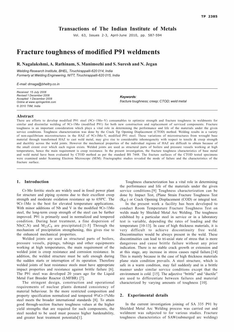
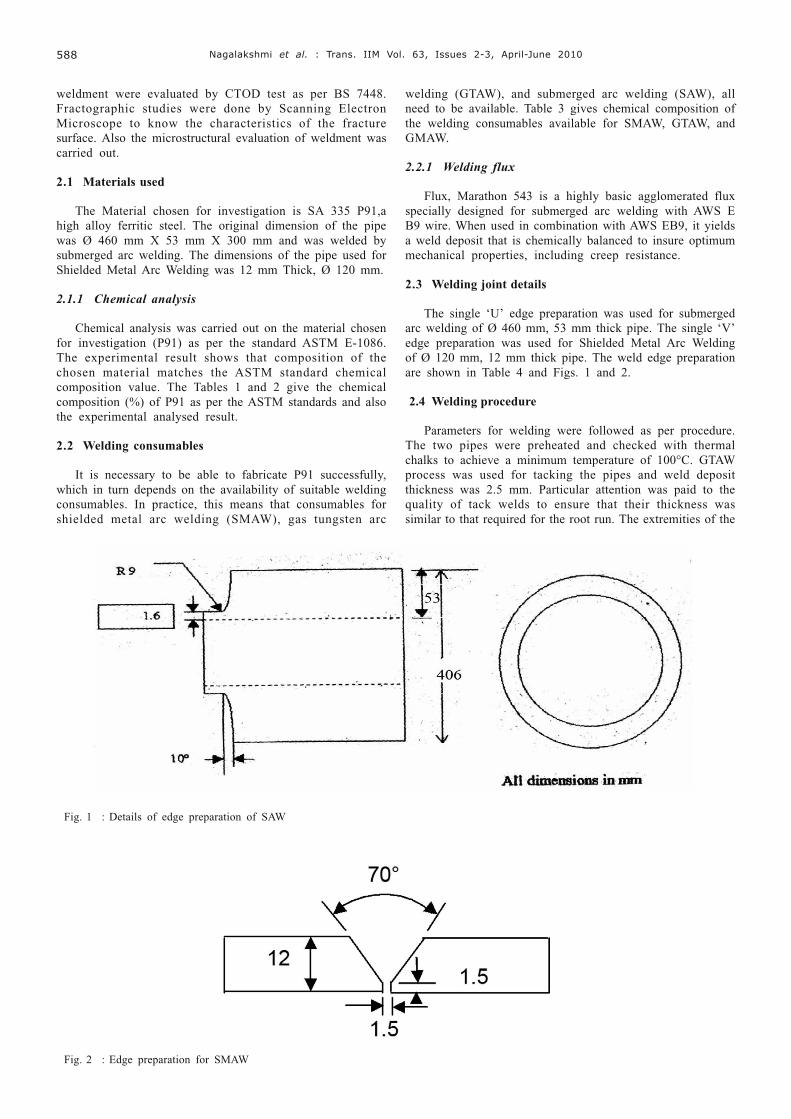
The single ‘U’ edge preparation was used for submergedarc welding of Ø 460 mm, 53 mm thick pipe. The single ‘V’edge preparation was used for Shielded Metal Arc Weldingof Ø 120 mm, 12 mm thick pipe. The weld edge preparationare shown in Table 4 and Figs. 1 and 2.
2.4 Welding procedure
Parameters for welding were followed as per procedure.The two pipes were preheated and checked with thermalchalks to achieve a minimum temperature of 100°C. GTAWprocess was used for tacking the pipes and weld depositthickness was 2.5 mm. Particular attention was paid to thequality of tack welds to ensure that their thickness wassimilar to that required for the root run. The extremities of the
Fig. 1 : Details of edge preparation of SAW
Fig. 2 : Edge preparation for SMAW

� ! � "�#$�� �%� ���� &� �� ���� ��'� ��� ��� ������� ����� ����������� ���� �
tack welds were dressed by grinding to facilitate properfusion where the root run was completed. Back purging byusing Argon was done to prevent oxidation inside the pipe.Then Shielded Metal Arc Welding process was used forfurther two passes and the weld metal deposit was 10 mm.The Shielded Metal Arc Welding stick electrodes after bakingwere stored in a portable oven at 150°C. Preheating using
producer gas burners for temperature of 220°C and wasmaintained before and during the course of welding. Thetemperature was checked using thermal chalks. Inter passtemperature was controlled between 230°C - 350°C and whentemperature exceeded the maximum, welding was stoppedand resumed after the temperature dropped to 230°C. Furtherpasses were done by using the SAW. Preheating and
Fig. 3 : Proportional dimensions and tolerances for a straight notch compact specimen.
Table 1: Chemical composition of SA 335 P91.
C Mn P S Si Cr Mo V Nb Ni N Al
Standard 0.08- 0.30- 0.02 0.01 0.50 8.00- 0.85- 0.18- 0.06- 0.40 0.03 0.030.12 0.60 max max max 9.50 1.05 0.25 0.10 max max max
Analyzed 0.08 0.42 0.02 0.01 0.3 8.24 0.9 0.21 0.05 - - -(Ø 120,12 mmthick pipe)
Analyzed 0.09 0.42 0.01 0.01 0.26 8.39 0.86 0.21 0.05 - - -(Ø 460, max max53 mmthick pipe)
Table 2 : Chemical composition of SAW welded P91.
C Mn P S Si Cr Mo V Ni Cu
Analyzed 0.12 0.72 0.01 0.01 0.21 8.19 0.82 0.19 0.75 0.10(SAW) max max max
Table 3 : Chemical composition of welding consumables
Consumable C Mn P S Si Cr Mo V Nb Ni N Al
E9018-B9 0.08- 1.25 0.02 0.01 0.30 8.00- 0.85- 0.15- 0.02- 1.0 0.02- 0.04(SMAW) 0.13 max max 10.5 1.20 0.30 0.10 0.07
E B9 (SAW) 0.07 1.25 0.01 0.01 0.30 8.0- 0.80- 0.15- 0.02- 1.0 0.03- 0.04-0.13 max max 10.0 1.10 0.25 0.10 0.07
Table 4 : Details of edge preparation
SAW SMAW SAW SMAW
Type of edge preparation Single U’ Single ‘V’ Root face width 1.6 mm 1.5mm
Wall Thickness 53 mm 12mm Root gap 1.6 mm 1.5 mm
Outside Diameter 406 mm 120mm Groove angle 10° 70°

�� � ! � "�#$�� �%� ���� &� �� ���� ��'� ��� ��� ������� ����� ����������� ����
Fig. 4 : Instron model 8502
Fig. 5 : Front view and Top view of the specimen dynamicmaterial testing system
Fig. 6 : Clip gauge arrangement with the compact tension
Fig. 7 : Fracture surface of the CTOD specimen
Fig.11: Micrograph of the weld metal (SMAW) at 170X
Fig.10: Micrograph of the face side weld metal (SAW) at 170 X
Figure 9: Micrograph of HAZ at 340 X
Figure 8: Micrograph of the P91 base metal at 340 X
First stage Second stageSpecimen
type RT 1 RT 2 0 °C RT 1 RT 2 0 °C
WELD 10904 13447 10004 17086 18244 19370
CTOD in mmSpecimen Type
Room temperature 0 °C
WELD METAL δm = 0.4656
δm = 0.4600
δu = 0.1521
BASE METAL δm = 0.6723
δm = 0.6509
δu = 0.2256
Table.5- Fatigue cycles for pre-cracking
Table 6: CTOD Test results
� ! � "�#$�� �%� ���� &� �� ���� ��'� ��� ��� ������� ����� ����������� ���� ��
interpass temperature were maintained as same. Oncompletion of welding the joints were given post heating at300°C and maintained for 2 hours by enclosing thermalblankets. Radiographic inspection was done after completionof weld and after grinding of the capping passes. Thensubjected to PWHT of 750°C for 260 minutes.
2.5 Fracture toughness (CTOD) testing
2.5.1 Equipment
The INSTRON model 8502, Dynamic Materials TestingSystems, is an advanced microprocessor based control
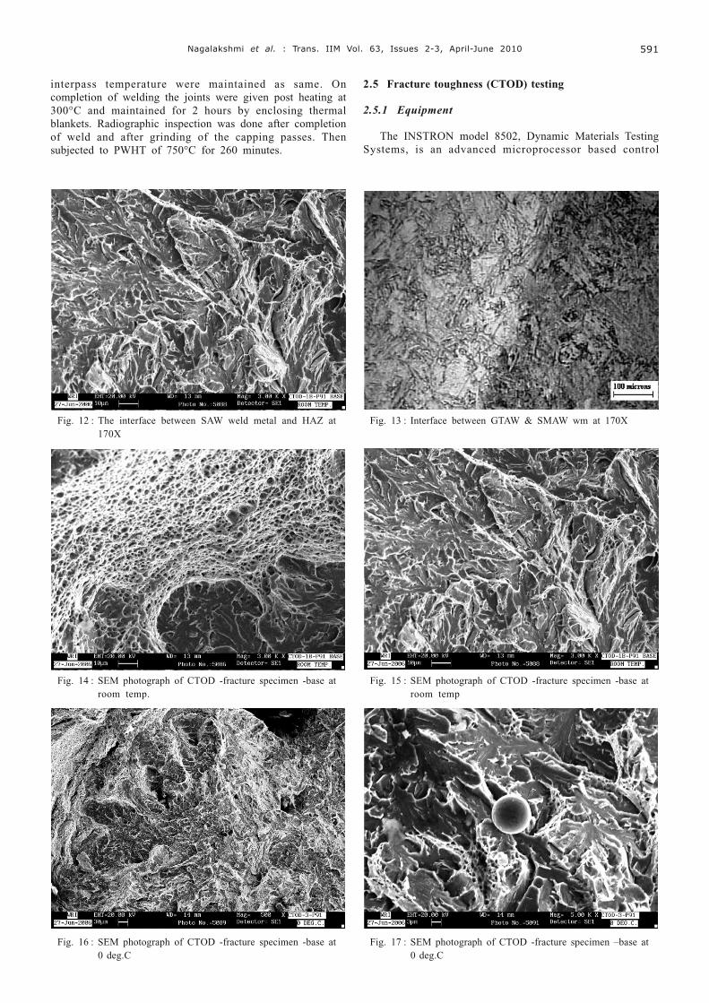
Fig. 12 : The interface between SAW weld metal and HAZ at170X
Fig. 13 : Interface between GTAW & SMAW wm at 170X
Fig. 15 : SEM photograph of CTOD -fracture specimen -base atroom temp
Fig. 14 : SEM photograph of CTOD -fracture specimen -base atroom temp.
Fig. 16 : SEM photograph of CTOD -fracture specimen -base at0 deg.C
Fig. 17 : SEM photograph of CTOD -fracture specimen –base at0 deg.C

�� � ! � "�#$�� �%� ���� &� �� ���� ��'� ��� ��� ������� ����� ����������� ����
console which provides full control of a testing system. Itincorporates a standard computer interface which is analternative to the front panel as a means of control systems.It has hydraulic grips of 300 KN capacity and pressure of 692bars for gripping the specimen can be used for Fracturemechanics test like KIC, CTOD, JIC test.
2.5.2 Specimen preparation for CTOD testing
Test specimens are cut by using power saw cuttingmachine along the T-L direction, as shown in Fig. 3 and thenmachined to determine the CTOD for weld. The compacttension specimens for weld locations were prepared inaccordance with BS standard 7448 part 1991-1. The CT(compact tension) specimen of width W=50 mm, thicknessB=25 mm was used. The length of the machined slot is 25mm, which is extended with a “V” groove notch of 5 mmusing spark erosion machine. The root radius of the groovewas maintained well within the E813 standard. A relative holeof 12.5-mm diameter was drilled on either side of the CTspecimen. The overall dimensions of the CT specimen areshown in the Fig. 3.
2.5.3 Fatigue precracking
Fatigue pre-cracking has been carried out for the entirespecimen as per BS standard, since it is impractical to obtaina reproducibly sharp, narrow machined notch that wouldsimulate a natural crack well enough to provide a satisfactoryCTOD test result. Pre-cracking of about 5mm length wascreated using INSTRON 8502 machine under load controlmode. The maximum force required for pre-cracking iscalculated as per the standard using the formula given below
Ff = 0.2B (W-a) 2 (σYS+ σUTS) / (2W+a) 1000 (1)
The fatigue pre-cracking load is calculated for weld. Inthe first stage, the maximum load is fixed at 90% of themaximum pre-cracking force (Ff). The first stage is continueduntil a pre-cracking length of 3 mm is reached. For the final2 mm, second stage is started during which the maximumload is limited to 70% of the maximum pre-cracking force (Ff)so as to achieve a very minute sharp crack. The procedurehas been repeated for all the CTOD specimens.
2.5.4 CTOD test procedure
The fatigue pre-cracked compact tension specimens arefixed in the INSTRON machine. A Clip gage of 10 mm gagelength with 4 mm travel is fitted to the knife-edges affixed inthe face of the compact tension specimen, so that clip gagemeasures displacement during testing exactly at mouth. Thetypical arrangement has been shown in the Fig. 4. The voltagesignals from the load cell and the clip gage are feed to x-yrecorder, which plots the graph between the force and clipgage displacement. The test is carried out in the staticloading and displacement controlled mode. After the testingis over static pulling breaks the specimen and the crack sizeis measured at nine equally spaced points centered about thespecimen centerline. The average value is taken as the cracksizes a0. From the Force Vs displacement plot the value ofF and Vp are obtained corresponding to the point of firstattainment of maximum force and the V corresponding to thatpoint on the x-axis where the line drawn parallel to the initialslope of the curve interests respectively.
2.5.5 Calculation of CTOD:
Using the dimensions B, W, (C-W) and z, the dimensiona0, the forces of Fc, Fu or Fm, and the corresponding valueof Vp, calculate either δc using Fc*** or δu using Fu or δmusingFm, from the following relationships.For a straight notchcompact specimen,
( ) ( )( )
22
0.5
1 0.46
2 0.46 0.54o po
YS o
W a VF af
W E W a C W zBW
νδ
σ
− −� �� �= × +� �� + + − + �� (2)
where f(a/W) is given by table specified in the standardBS7448.
2.6 Crack tip opening displacement (CTOD) test
2.6.1 Weld metal
Test Standard: BS 7448 Specimen Type: CTSpecimen Orientation: T–L Displacement Measured At:
MouthMaterial Data: σ UTS = 669 MPa, σYS = 574 MpaYoungs Modulus = 210000 Mpa, Poisson’s Ratio = 0.3
a. SPECIMEN DETAILS:Thickness, B = 25 mmWidth, W = 50 mmNotch Length, NL = 27.5 mmTotal width, C = 62.5 mmKnife edge thickness Z = 1.5 mmExpected Crack Length = 22.5 mm
b. Fatigue precracking detailsThe maximum force required for pre-cracking is
calculated as per the standard using the formula,Fmax= 0.2B (W-a)2 (σYS+ σUTS) / (2W+a) 1000. MaximumFatigue load (Fmax) = 38.368 kN
b.1. FIRST STAGE (90%) of the maximum calculated load:Pmax = 34.5312 kNPmin=3.45 kNPmean = 18.99 kNPamp = 15.54 kN
b.2 FINAL (70%) of the maximum calculated load:Pmax = 26.87 kN Pamp = 12.082 kNPmin=2.685 kN Frequency=5HzPmean = 14.7675 kNX-Y RECORDER: INSTRON VALUE:X-axis: 0.1V/cm A = 0.9 mmY-axis:V/cm B=12 kN
2.6.2 Base metal
Material Data: σUTS = 669 MPa, σYS = 574 MpaYoungs Modulus = 210000 Mpa, Poisson’s Ratio = 0.3
a. SPECIMEN DETAILS:Thickness, B = 18 mmWidth, W = 50 mmNotch Length, NL = 27.5 mmTotal width, C = 62.5 mmKnife edge thickness Z = 1.5 mmExpected Crack Length = 22.5 mmFATIGUE PRECRACKING DETAILS:Calculated similar to weldmetal.

� ! � "�#$�� �%� ���� &� �� ���� ��'� ��� ��� ������� ����� ����������� ���� ��
2.6.3 Calculation of CTOD
After the testing a0 values are measured from the 9 spotsof fractured specimen, and average values of a0 calculatedfrom measurements. Force and plastic component (Vp) werecalculated from the graph obtained from the X-Y recorder.Calculations of CTOD were made as per standard, shown inTable 6.
2.7 Microstructural characterisation
An immersion etching for 15-30s in Villela’s reagent wasadequate to reveal the constituents of the microstructure.Microphotograph were taken in the regions of weld metal,HAZ, interface between HAZ & weld metal, parent metal,and interface between parent metal & HAZ.
2.8 SEM analysis of fracture surface
SEM examination of the fracture surfaces of all the CTODtested specimens were carried out. Fracture surfaces wereultrasonic cleaned and were examined in SEM. Then thefractographs were compared together.
3. Results and discussion
3.1 CTOD results
Force and plastic component (Vp) were calculated fromthe graph obtained from the X-Y recorder. From the table-6,the weld metal shows less CTOD value compare to thebasemetal result at the temperatures of 0 °C and roomtemperature (27°C). The reasons for the lower toughness ofthe welds are probably due to the coarse martensite andcarbide precipitates surrounded by δ ferrite subgrains wherethe matrix carbide interfaces may act as the most likely sitesfor crack nucleation.
3.2 Optical microscopy examination
Microstructural analysis using light optical microscopehas identified the tempered martensite and globular carbidesin the base metal as the critical features for the high value
of CTOD. The P91 base metal consists of temperedmartensitic structure and finely distributed carbides andcarbonitrides (Fig. 8 ). Figure 9 shows the HAZ microstructureof fine martensite with finely distributed carbides. Theprecipitates of these regions are probably M23C6 and QX(Nb-V carbonitrides). Micrograph of the SAW- weld top(figure.10) shows the martensite with the fine δ-ferrite. Finermartensite is formed by grain refinement during the multipasswelding. The formation of δ ferrite in the weld metalmicrostructure during the solidification restricts the graingrowth and grain size. However, martensite gradually losesits acicular feature because of the PWHT. The Shielded MetalArc Welding weld metal structure (Fig. 11) exhibits finemartensitic structure compared to the SAW weld metal, thismay be because of the low heat input which can acceleratesthe fast cooling rate. The micro photographs show theinterface between weld metal and HAZ. (12&13) The SAWshows the wider fusion boundary as compared to theShielded Metal Arc Welding fusion boundary. Also coarsegrain structure of HAZ is observed in the SAW weld side.
3.3 SEM-fracture characterization studies
Crack initiation at the carbide matrix interface by blockedslipped bands is more difficult with globular carbides thanwith angular carbides. Carbide precipitates surrounded by δferrite subgrains where the matrix–carbide interfaces may actas the most likely sites for crack nucleation The fractureappearance of a CTOD fracture surface at room temperatureexhibits extensive dimple fracture with micro voids as shownin Fig. 14. The fracture surface of the base metal-CTODfracture surface at room temp. shows fully brittle fracturewith more number of micro voids (Fig. 15). CTOD fracturesurface at 0 deg.C. shows fully brittle fracture with lessnumber dimples (fig.16). Large sizes of voids with dimplefracture are observed in the fracture surface of CTOD–basemetal fractured at 0°C (Fig. 17). The fracture surface exhibiteda mixed mode of brittle as dominating feature with somedimple appearance characteristic of micro void coalescencewith grain boundary facets with smaller number of dimples.Similar features were seen in the fig-.18 in the fracture surfaceof CTOD–base metal. The fracture surface of CTOD–basemetal shows fully ductile and dimple fracture and micro voidswith some cleavage facets (Fig. 19).
Fig. 19 : SEM photograph of CTOD -fracture specimen -base atroom temp
Fig. 18 : SEM photograph of CTOD -fracture specimen -base atroom temp

�� � ! � "�#$�� �%� ���� &� �� ���� ��'� ��� ��� ������� ����� ����������� ����
4. Conclusions
Major conclusions drawn from this study relating to theevolution of the microstructures, CTOD and fracturecharacteristics of 9Cr-1Mo-V weldment are given below:
� The Base metal evaluation has shown that the P91 steelchosen for the work has the composition within thespecific limit. The toughness is also meeting therequirements.
� Welding procedure for P91 pipe with root pass weldingof GTAW and subsequent passes of Shielded Metal ArcWelding and SAW was developed and which werequalified as per the standard ASME SEC-IX.
� It was observed that the base metal exhibits the highesttoughness compared to the weld metal due to thetempered martensite and globular carbides in the basemetal microstructure.
� The weld metal shows the lower CTOD values comparedto the base metal at the temperatures of 0°C and roomtemperature (27°C). The critical features for the lessvalue of CTOD are the coarse martensite and carbideprecipitates surrounded by δ ferrite subgrains where thematrix–carbide interfaces may act as the most likely sitesfor crack nucleation.
� Microstructural analysis identified the coarse martensiteand carbides with δ ferrite in the weld metal region. Basemetal microstructure consists of tempered martensiticstructure and finely distributed carbides, and HAZconsists of martensite with finely distributed carbides.
References
1. Swindeman R W, Santella M L, Maziasz P J, Roberts B W andColeman K, International Journal of Pressure Vessels and Piping,81 (2004) 507.
2. Spiradek K, Bauer R and Zeiler G, Materials for Advanced PowerEngineering, 1994, Kluwer Academic Publishers, Dordrecht,(1994) 251.
3. Eva-Lena Bergquist, Esab AB, Goteborg, Svetsaren.1–2 , CentralLaboratories in Goteborg, Sweden, (1999) 22.
4. Knott J K, Fundamentals of Fracture Mechanics, (1976) 205. Laha K, Chandravathi K S, Bhanu Sankara Rao S and
Mannan S L, International Journal of Pressure Vessels andPiping, 62 (1995) 303.
6. Anon, Guide to the Welding and Weldability of Cr-Mo andCrMoV Heat Resisting Steels, IIW Doc.IXG-319 (1986) 43.
7. Regev M, Welding Journal, (1996) 261.8. Khare A K, Ferritic Steels for High-Temperature Applications,
Conference Proceedings ASM, Metals Park OHIO, 6-8 (1981)85.9. Lundin C D, WRC Bulletin, 454 (2000) 1.10. David Broek, Elementary Engineering Fracture Mechanics,
Vorbooff International (1974) 46.11. Patron V Z and Morozov E M, “Elastic Plastic Fracture
Mechanics”, Mir Publishers Moscow (1978) 26.12. Dittrich S and Heuser H, Welding of T/P 91 Steel with Optimized
Filler Metal Addition, Technical Information HC/4-105, BohlerThyssen Welding Institute 7.
13. Blame R, Leich K E, Heuser K E and Meyer F W, Welding ofmodified 9% Cr steel, Technical Information HC/4-105, BohlerThyssen Welding Institute 1.
14. Heuser H, GTA- and SA-welding of the 9%Cr-Steel T9l/P91,The 73rd Annual AWS-convention, March 24, Chicago (1992).
15. Sperko Engineering Services, Inc. Welding Grade 91 Alloy Steel(2005) 2.