effect of postweld heat treatment on the toughness of heat...
TRANSCRIPT
MARCH 2013, VOL. 9280-s
WE
LD
ING
RE
SE
AR
CH
Introduction
Grade 91 steel, known as the modified9Cr-1Mo-V, designated as P91 for pipeand plate (ASTM A335 P91), and T91 fortube (ASTM A213 T91), is a creep-en-hanced ferritic steel that has been widelyused in power-generating applications as aheader, superheater, and reheater. Ini-tially developed by Sikka et al. (Ref. 1), thealloy was to have an improved strengthand toughness for liquid metal fastbreeder reactor. Then the alloy was mod-ified by adding vanadium, nickel, alu-minum, niobium, and nitrogen to becomethe modified 9Cr-1Mo-V steel. Propertiessuch as high thermal conductivity, betterresistance to stress corrosion cracking,lower thermal expansion coefficient, andhigh resistance to thermal fatigue made
Grade 91 a better replacement for loweralloy steels for piping and vessels. With su-perior mechanical properties such asyield, ultimate tensile, and creep rupturestrengths matching or exceeding that of9Cr-1Mo, 21⁄4Cr-1Mo, HT9, EM12, and304 stainless, Grade 91 was identified(Ref. 2) as a material of choice in thepetrochemical and nuclear industry.
The as-received material of Grade 91undergoes normalizing-and-temperingheat treatment to achieve better mechan-ical properties. The ASME code requiresthat the steel be normalized at1038°–1149°C and tempered at a mini-
mum temperature of 732°C. A fully tem-pered martensite matrix, with finely dis-persed carbides, and carbo-nitrides pre-cipitation on the grain boundaries, is thetypical microstructure. The carbides are ofM23C6-type, M being metallic elements,mainly Cr and Fe, Mn, and Mo if present;and the grain boundary carbonitrides areof MX-type, M being Nb and V, and Xbeing C and N (Ref. 3).
When the as-received material under-goes manufacturing processes such as weld-ing, the mechanical properties will changedue to phase transformations, including theformation of fresh martensite. It becomesnecessary to conduct a postweld heat treat-ment (PWHT) below the AC1 temperaturefor some period of time to temper themartensite and achieve the desired mi-crostructure and mechanical properties.Because the degree of martensitic harden-ing depends upon the material chemicalcomposition and welding conditions, thecorrect control of time and temperature forthe PWHT becomes critical. Instead of onlyperforming tempering, it would be better todo both normalizing and tempering afterwelding to achieve better creep propertiesas suggested by Santella et al. (Ref. 4).
The impact toughness as influenced byPWHT becomes important when control-ling the delayed weld cracking during man-ufacturing, the room-temperature pressuretesting, and startup of a unit after installa-tion and maintenance. Although variouspapers have been published on impacttoughness of the weld metal Grade 91(Refs. 5–7), the toughness of the heat-affected zone (HAZ) has not been studiedin detail. The objective of this paper is tostudy the impact toughness of the HAZs inGrade 91 joints as affected by PWHT bothbelow and above the AC1 temperature.
Experimental Procedure
Welding and Heat Treatment
ASTM A335 P91/ASME SA335 P91 pipe
Effect of Postweld Heat Treatment onthe Toughness of Heat-Affected Zone
for Grade 91 SteelAfter investigating the impact toughness of the heat-affected zone for
Grade 91 steel welds, it was discovered that 760°C for 2 h postweld heat treatment can significantly increase the cross-weld toughness
of the heat-affected zone
BY B. SILWAL, L. LI, A. DECEUSTER, AND B. GRIFFITHS
KEYWORDS
Heat-Affected Zone (HAZ)Grade 91Postweld Heat Treatment(PWHT)
AC1 Temperature
B. SILWAL, L. LI ([email protected]), A. DE-CEUSTER, and B. GRIFFITHS are with the De-partment of Mechanical & Aerospace Engineering,Utah State University, Logan, Utah.
Presented during the AWS Professional Program atFABTECH 2012, Las Vegas, Nev.
ABSTRACT
The impact toughness of the heat-affected zone (HAZ) for Grade 91 steel weldshas been experimentally investigated. The as-welded multipass HAZ has a significantscatter in toughness, due to variations in the Charpy notch location and the path offracture propagation. The cross-weld Charpy specimen gives a toughness value thatcan be attributed to contributions by the weld metal, various HAZ regions, and thebase metal. The microstructure evolution of various HAZ regions during postweld heattreatment (PWHT) has been investigated and used to explain the toughness changes.A 760°C for 2 h PWHT can significantly increase the cross-weld toughness of the HAZ.The measured weld HAZ toughness can be understood using a linear additive modelthat employs as the inputs the toughness values of various HAZ regions reproducedon the Gleeble®. The toughness of the coarse-grained heat-affected zone (CGHAZ)recovers the slowest as a function of increasing PWHT temperature, and remains lowuntil a 730°C heat treatment. To guarantee an adequate HAZ toughness, a PWHT ofat least 730°C is recommended. Postweld heat treatment above the AC1 temperaturewill result in the formation of fresh martensite, which decreases the toughness and in-creases the hardness of all HAZ regions. Postweld heat treatment 20°C below the AC1temperature for 2 h has produced the highest toughness and lowest hardness of allHAZ regions.
SILWAL ET AL SUPPLEMENT MARCH 2013layout_Layout 1 2/14/13 4:39 PM Page 80
81-sWELDING JOURNAL
WE
LD
ING
RE
SE
AR
CH
was used as base metal. The as-receivedpipe had an 8.625 in. (219 mm) outer di-ameter, 1.143 in. (29 mm) thickness, andwas normalized for 8 min at 1060°C andtempered for 45 min at 786°C. The chem-ical composition of the material is given inTable 1.
Two 5-in.- (127-mm-) long pipes werewelded together by gas tungsten arc welding(GTAW) and flux cored arc welding(FCAW) processes. The double-V weldgroove had a 60-deg included angle with a1.5-mm root face. The same process was re-peated eight times to conduct a full factorialdesign of the welding process parameters ofmaximum and minimum preheat tempera-ture, interpass temperature, and heat input(as mentioned maximum being high andminimum being low hereafter). Gas tung-sten arc welding was used for the root passwith 300 A DC and 1.27 m/min wire feedspeed, and FCAW was used for the fillingpasses with 26.1 and 27 V arc voltage and6.35 and 7.62 m/min wire feed speed. The0.14 m/min linear travel speed was main-tained by a stepper motor controlled fixture.Pure argon shielding was used for GTAWand mixed 75/25 argon/CO2 shielding wasused for FCAW. The filler metal was 1.2-mm-diameter ER90S-B9 for GTAW, andER91T1-B9 for FCAW. The linear travelspeed was 0.292 m/min.
Sixteen Type-K thermocouples wereplaced on different locations from theedge of the weld groove to measure thetemperature profile. Two 8-channel dataloggers were used to record the tempera-ture measurements with a sampling fre-quency of 5 Hz. After welding, the loca-tions of the thermocouples wereremeasured relative to the weld interfaceline, which was assumed to have experi-enced the melting temperature. The mi-crostructure from the HAZ of the as-welded specimen was then analyzed, andthe HAZ locations were identified andmeasured from the weld interface. For in-stance, the intercritical heat-affected zone(ICHAZ) was identified to be about 2.1
mm from the weld interface for weld #5.The thermocouple located at or near 2.0mm from the weld interface was then iden-tified as that representing the ICHAZ
thermal cycle.The interpass temperature was also
maintained with the use of a ceramic padheater and surface temperature probe
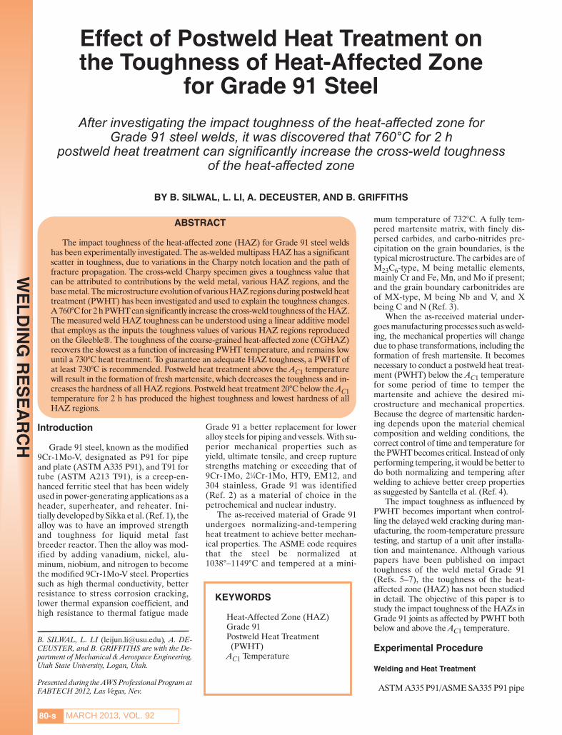
Fig. 1 — Schematic of the Charpy coupon extraction and location of thenotch relative to the weld metal on the left and HAZ in the base metal.
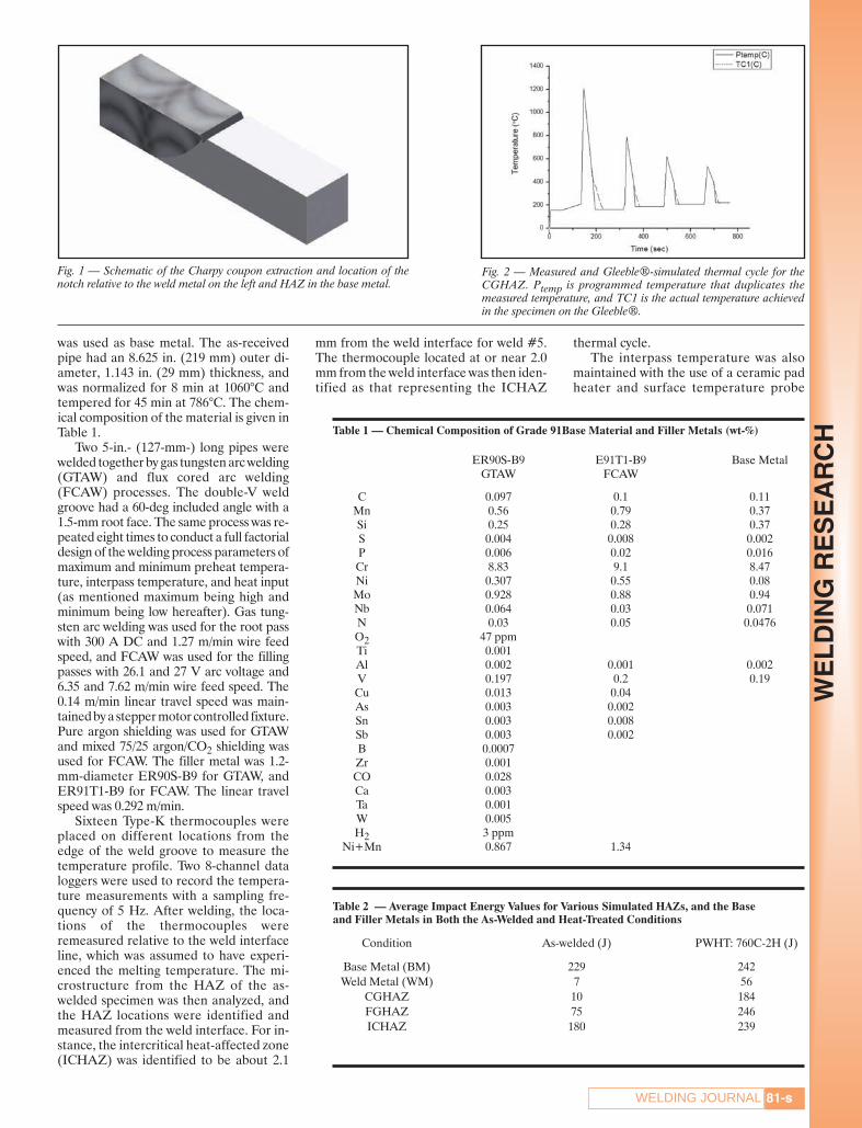
Fig. 2 — Measured and Gleeble®-simulated thermal cycle for theCGHAZ. Ptemp is programmed temperature that duplicates themeasured temperature, and TC1 is the actual temperature achievedin the specimen on the Gleeble®.
Table 1 — Chemical Composition of Grade 91Base Material and Filler Metals (wt-%)
ER90S-B9 E91T1-B9 Base MetalGTAW FCAW
C 0.097 0.1 0.11Mn 0.56 0.79 0.37Si 0.25 0.28 0.37S 0.004 0.008 0.002P 0.006 0.02 0.016Cr 8.83 9.1 8.47Ni 0.307 0.55 0.08Mo 0.928 0.88 0.94Nb 0.064 0.03 0.071N 0.03 0.05 0.0476O2 47 ppmTi 0.001Al 0.002 0.001 0.002V 0.197 0.2 0.19Cu 0.013 0.04As 0.003 0.002Sn 0.003 0.008Sb 0.003 0.002B 0.0007Zr 0.001CO 0.028Ca 0.003Ta 0.001W 0.005H2 3 ppm
Ni+Mn 0.867 1.34
Table 2 — Average Impact Energy Values for Various Simulated HAZs, and the Base and Filler Metals in Both the As-Welded and Heat-Treated Conditions
Condition As-welded (J) PWHT: 760C-2H (J)
Base Metal (BM) 229 242Weld Metal (WM) 7 56
CGHAZ 10 184FGHAZ 75 246ICHAZ 180 239
SILWAL ET AL SUPPLEMENT MARCH 2013layout_Layout 1 2/14/13 4:39 PM Page 81
MARCH 2013, VOL. 9282-s
WE
LD
ING
RE
SE
AR
CH with an accuracy of temperature control at
± 10°C. The preheat temperature beforewelding was between 150° and 250°C. Theinterpass temperature during welding wasbetween 200° and 300°C. A pneumaticdescaler and wire brushing were used forslag removal. A postweld bake-out at250°C temperature for 4 h was conductedwith temperature-controlled ceramic heatpads. Subsequently, the as-welded jointswere PWHT in a furnace for 2 h at varioustemperatures.
Impact Test
Charpy impact specimens were ex-tracted in the pipe’s longitudinal directionfrom the middle thickness of both the as-welded and PWHT joints. Standard Charpyimpact V-notch specimens (10 × 10 × 25mm) were prepared according to ASTMA370 (Ref. 8). All specimens weremacroetched to reveal the fusion boundary,which served as the location for the notch sothat the fracture path would traverse theHAZ — Fig. 1. Three specimens in the as-
welded condition and four specimes in thePWHT condition were impact tested atroom temperature. Standard metallo-graphic procedure was followed to preparethe specimens for optical microscopy. Thepolished specimens were etched with theNital (10% nitric acid in methanol) or LePera reagent (4% picric acid in ethanolmixed with a 1% sodium metabisulfite indistilled water in an 1:1 volume ratio) to an-alyze the microstructure.
Microstructure Simulation
To “magnify” the small HAZ regions sothat large samples of similar microstruc-ture can be tested, a Gleeble® 1500D wasused to simulate the multipass weldingprocess. The measured thermal cycle foreach individual HAZ was reproduced inthree smooth Charpy specimens. As an ex-ample, the thermal cycle for the as-weldedcoarse-grained heat-affected zone(CGHAZ) is shown — Fig. 2. The simu-lated samples were then heat treated atdifferent temperatures from 600° to 840°C
with a temperature difference of 40°C.Notches were machined in the middle ofthe test specimens. Two specimens foreach tempering temperature were testedand both results were reported.
The average energy values for these“pure” metals (of the simulated HAZ re-gions, fusion zone, and base metal) arelisted in Table 2. This method of creatingsimulated samples by using the thermalcycle is different from most previous stud-ies, because not only the first peak tem-perature but also the subsequent temper-ature peaks by multipasses were applied toachieve similar properties of the as-welded samples. The transformation tem-peratures AC1, AC3, Ms, and Mf tempera-ture for the Grade 91 base metal were alsomeasured using dilatometry on the Glee-ble®. The specimen was heated at a rateof 100°/min from room temperature to728°C, then the heating rate was switchedto 28°/h to heat to 1300°C, at which pointthe specimen was allowed to naturally coolto room temperature. A precise exten-someter measured the diameter change
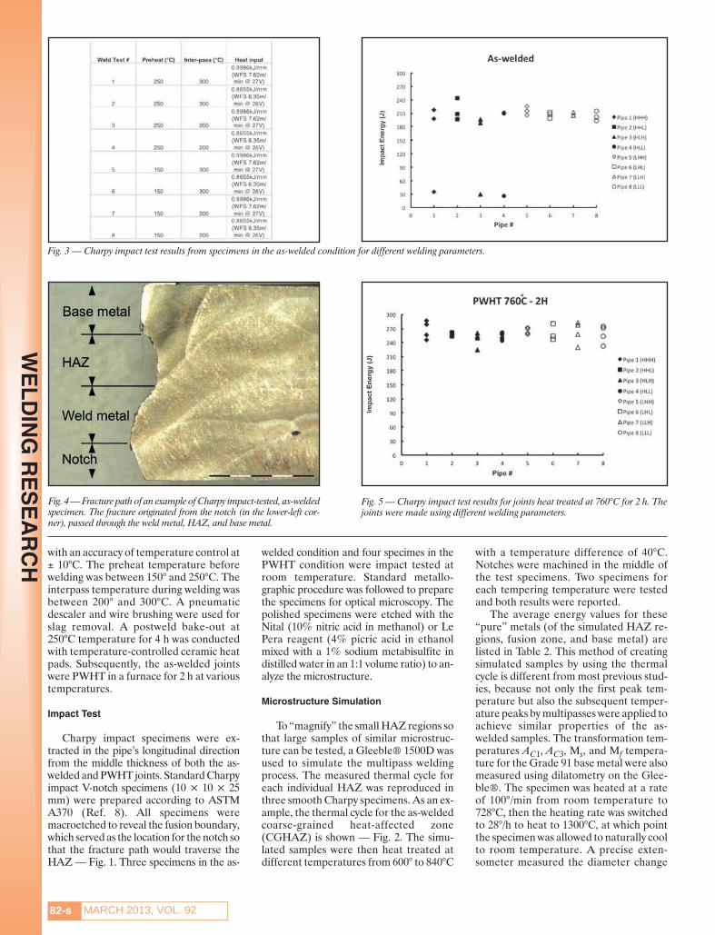
Fig. 3 — Charpy impact test results from specimens in the as-welded condition for different welding parameters.
Fig. 4 — Fracture path of an example of Charpy impact-tested, as-weldedspecimen. The fracture originated from the notch (in the lower-left cor-ner), passed through the weld metal, HAZ, and base metal.
Fig. 5 — Charpy impact test results for joints heat treated at 760°C for 2 h. Thejoints were made using different welding parameters.
°
SILWAL ET AL SUPPLEMENT MARCH 2013layout_Layout 1 2/14/13 4:39 PM Page 82
83-sWELDING JOURNAL
WE
LD
ING
RE
SE
AR
CH
during the entire heating and coolingprocess.
Results and Discussion
Toughness of the HAZ
The impact energy values for theHAZs in the as-welded samples are shownin Fig. 3. The average impact energy ex-ceeds 180 J for the as-welded samples. Thedifference in impact energy values withdifferent process parameters during weld-ing is not significant, although a greaterpreheat temperature (250°C) seems tohave produced wider scatter in impact en-ergy of the HAZ. Lower preheat (150°C)seems to have produced a much narrowerscatter band in impact energy of the HAZ.A few as-welded samples have impact en-ergy values close to 30 J.
An inspection of the fracture path re-veals the propagation of fracture in theselow toughness specimens originates fromthe notch and passes through the weldmetal, HAZ, and base metal — Fig. 4. Theweld metal in the as-welded condition hasan impact energy of 7 J. Clearly, the meas-ured impact energy is a sensitive function
of the position of thenotch for the heteroge-neous weld joint. Similarobservations have beenmade by other re-searchers, such asMoitra et al. (Ref. 10)and Jang et al. (Ref. 11),in a study of the effect ofnotch location on impacttoughness of weld metaland HAZ.
After a PWHT at760°C for 2 h, the im-pact energy of all HAZspecimens has increasedconsistently — Fig. 5.The minimum energylevel for joints madeusing different weldingparameters is 220 J. The wide scatter ofimpact energy levels for the as-weldedweld HAZ has been narrowed down. Aninspection of fractography of testedspecimens revealed the fracture paths tobe consistently starting from the notch,traversing the HAZ and base metal.None of the fracture paths in the heat-treated samples has deviated into the
weld metal, which after the 760°C for 2 hheat treatment, has the impact toughnessincreased from 7 to 56 J.
Contribution to Toughness by IndividualZones
The Gleeble®-simulated microstruc-ture is verified to be similar to that from the
A B
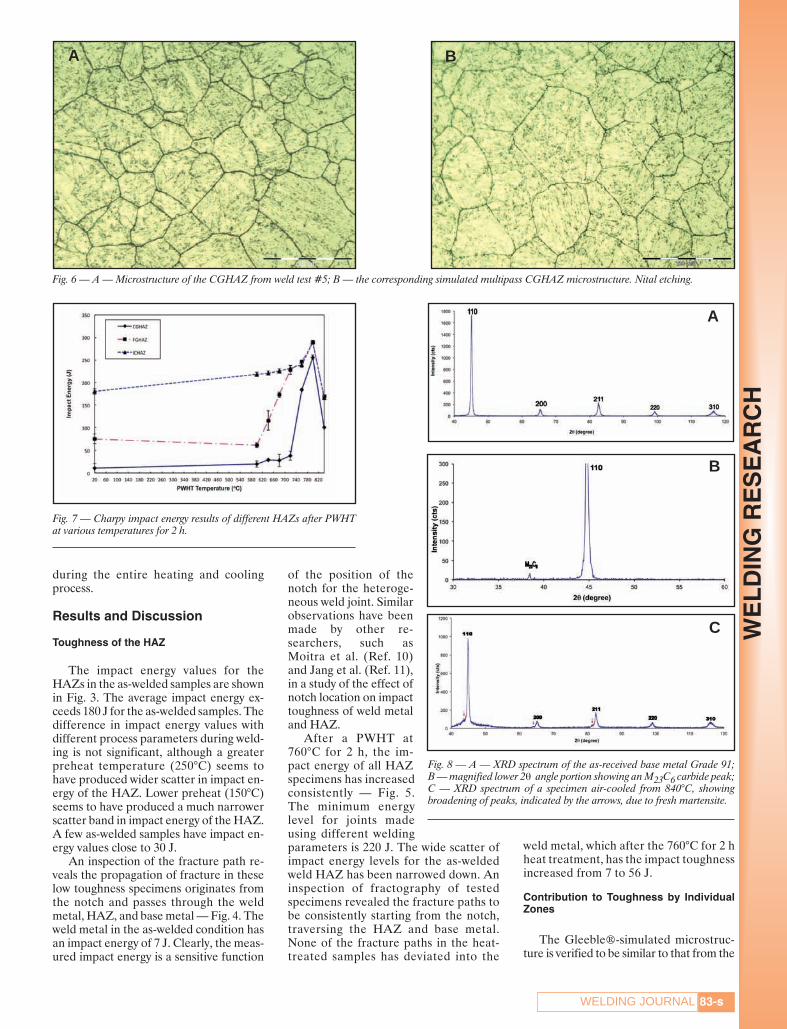
Fig. 6 — A — Microstructure of the CGHAZ from weld test #5; B — the corresponding simulated multipass CGHAZ microstructure. Nital etching.
Fig. 7 — Charpy impact energy results of different HAZs after PWHTat various temperatures for 2 h.
Fig. 8 — A — XRD spectrum of the as-received base metal Grade 91; B — magnified lower 2θ angle portion showing an M23C6 carbide peak;C — XRD spectrum of a specimen air-cooled from 840°C, showingbroadening of peaks, indicated by the arrows, due to fresh martensite.
A
C
B
SILWAL ET AL SUPPLEMENT MARCH 2013layout_Layout 1 2/14/13 4:39 PM Page 83
MARCH 2013, VOL. 9284-s
WE
LD
ING
RE
SE
AR
CH
HAZs of the welded samples. An examplecomparison of microstructures for theCGHAZ is shown in Fig. 6. The two mi-crostructures not only share the same grainsize, but also the martensitic substructure,size, and amount of carbide particles. Suchsimulated microstructure for the entirecross-section of the Charpy specimen en-ables an accurate evaluation of impacttoughness of individual HAZs.
The Charpy impact results of the simu-lated HAZ samples heat treated at varioustemperatures for 2 h are shown in Fig. 7.Among the three HAZ regions, the ICHAZexhibits the highest toughness, while theCGHAZ has the lowest toughness and fine-grained heat-affected zone (FGHAZ) hasan intermediate toughness. The CGHAZexhibits the lowest impact energy followinga 600°C, 2-h heat treatment. This low tough-ness remains until the PWHT temperatureis at 720°C. The impact energy of CGHAZthen increases significantly when thePWHT temperature is 760°C. A PWHT at800°C results in the peak toughness for the
CGHAZ. The impact toughness then de-creases when the PWHT temperature is840°C. The ICHAZ toughness remains at220 J for PWHT temperatures below 760°C,and reaches the peak value following an800°C heat treatment. The ICHAZ tough-ness also decreases when the PWHT tem-perature is 840°C. The FGHAZ toughnessincreases with a higher PWHT temperaturebetween 600° and 720°C. After the 720°CPWHT, the FGHAZ toughness has in-creased to the same level as that of theICHAZ. Further increases in the PWHTtemperature from 720°C result in the exactsame toughness for both the FGHAZ andICHAZ. A notable trend is that all HAZ re-gions reach the peak toughness following an800°C PWHT; and all HAZ regions losetoughness following an 840°C PWHT.
The measured impact toughness re-ported in Fig. 5 represents the total energyfor the fracture to traverse the entire speci-men. The fracture path may have traversedthe weld metal, various HAZ zones, and thebase metal. As a first approximation, we canconsider the total impact energy (ECalc) tobe consisted of a linear summation of con-tributions by various zones as follows:
ECalc = (ECGHAZ + EFGHAZ + EICHAZ) +EWM+ EBM (1)
where ECGHAZ is the energy contributionof the CGHAZ, EFGHAZ is the energycontribution of the FGHAZ, EICHAZ is theenergy contribution of the intercriticalHAZ, EWM is the energy contribution ofthe weld metal, and EBM is the contribu-tion of the base metal.
Because the Charpy specimen has auniform width, the contribution of indi-vidual zones to the total Charpy impactenergy can be calculated using the meas-ured fracture length in each zone. For ex-ample, for the contribution of base metal(EBM) to the total impact energy, the fol-lowing formula can be used:
where LBM is the length of the fracturepath that falls in the base metal, LTotal isthe total length of the fracture path of theCharpy specimen, and E’BM is the meas-ured impact energy of the “pure” basemetal. Similar definitions can be made forECGHAZ for the CGHAZ, EFGHAZ for theFGHAZ, and EICHAZ for the ICHAZ, re-
E = LL
E' (2)BMBM
TotalBM
⎛
⎝⎜
⎞
⎠⎟
Table 3 — Sample Calculation of Contributions of Base Metal and HAZ to the Total Impact Energy
As-welded PWHT: 760C-2H
LCGHAZ (mm) 0.5 0.7LFGHAZ (mm) 0.7 0.8LICHAZ (mm) 0.3 0.5
LBM (mm) 6.0 6.0ECGHAZ (J) 0.6 16EFGHAZ (J) 9 24EICHAZ (J) 6 15
EBM (J) 203 187ECalc (J) 220 243EExp (J) 210 257
Difference (%) –5 5
The LCGHAZ value is the measured fracture length, ECGHAZ value is the calculated contribution to impactenergy by CGHAZ, ECalc is calculated total impact energy, and EExp is the measured total impact energy fromthe welded sample.
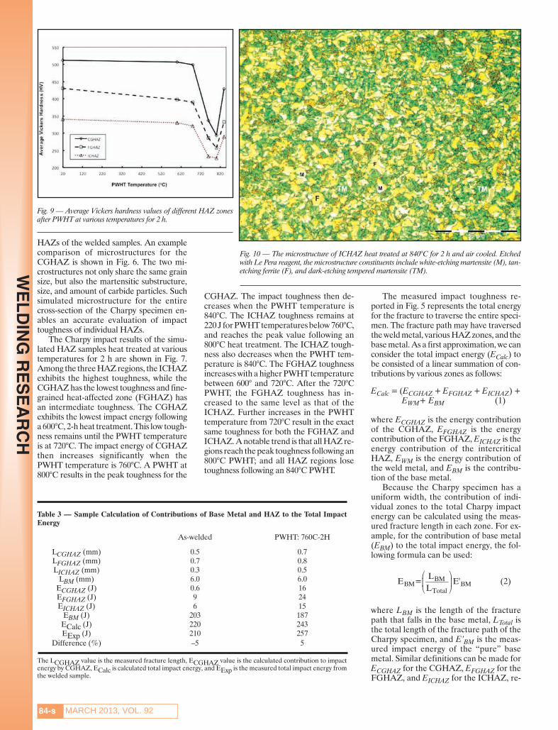
Fig. 9 — Average Vickers hardness values of different HAZ zonesafter PWHT at various temperatures for 2 h.
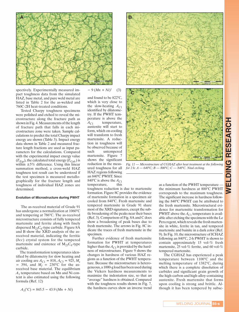
Fig. 10 — The microstructure of ICHAZ heat treated at 840°C for 2 h and air cooled. Etchedwith Le Pera reagent, the microstructure constituents include white-etching martensite (M), tan-etching ferrite (F), and dark-etching tempered martensite (TM).
SILWAL ET AL SUPPLEMENT MARCH 2013layout_Layout 1 2/15/13 1:58 PM Page 84
85-sWELDING JOURNAL
WE
LD
ING
RE
SE
AR
CH
spectively. Experimentally measured im-pact toughness data from the simulatedHAZ, base metal, and pure weld metal arelisted in Table 2 for the as-welded and760C-2H heat-treated conditions.
Tested Charpy toughness specimenswere polished and etched to reveal the mi-crostructure along the fracture path asshown in Fig. 4. Measurements of the lengthof fracture path that falls in each mi-crostructure zone were taken. Sample cal-culations to predict the total Charpy impactenergy are shown (Table 3). Impact energydata shown in Table 2 and measured frac-ture length fractions are used as input pa-rameters for the calculations. Comparedwith the experimental impact energy value(EExp), the calculated total energy (ECalc) iswithin ±5% difference. Using this linearsummation method, a cross-weld HAZtoughness test result can be understood ifthe test specimen is measured metallo-graphically for the fracture length andtoughness of individual HAZ zones are determined.
Evolution of Microstructure during PWHT
The as-received material of Grade 91has undergone a normalization at 1060°Cand tempering at 786°C. The as-receivedmicrostructure consists of fully temperedmartensite and ferrite along with finelydispersed M23C6-type carbide. Figure 8Aand B show the XRD analysis of the as-received material, indicating the ferritic(bcc) crystal system for the temperedmartensite and existence of M23C6-typecarbide.
The transformation temperatures iden-tified by dilatometry for slow heating andair cooling are AC1 = 818, AC3 = 925, Ms= 394, and Mf = 230°C for the as-received base material. The equilibriumA1 temperature based on Mn and Ni con-tent is also estimated using the followingformula (Ref. 12)
A1(°C) = 845.5 − 43.9 (Mn + Ni)
− 9 (Mn + Ni)2 (3)
and found to be 822°C,which is very close tothe slow-heating AC1identified by dilatome-try. If the PWHT tem-perature is above theAC1 temperature,austenite will start toform, which on-coolingwill transform to freshmartensite. A reduc-tion in toughness willbe observed because ofsuch untemperedmartensite. Figure 7shows the significantreduction in the meas-ured toughness for allHAZ regions followingan 840°C PWHT. Since840°C is above the AC1temperature, thistoughness reduction is due to martensiteformation. Figure 8C provides the evidenceof martensite formation in a specimen aircooled from 840°C. Fresh martensite andtempered martensite in Grade 91 sharemost of the XRD signatures, except the sub-tle broadening of the peaks near their bases(Ref. 3). Comparison of Fig. 8A and C doesshow a broadening of peak bases due tofresh martensite. The arrows in Fig. 8C in-dicate the traces of fresh martensite in thespecimen.
Further evidence of fresh martensiteformation for PWHT at temperatureshigher than the AC1 is provided by the hard-ness of microstructure. Figure 9 shows thechanges in hardness of various HAZ re-gions as a function of the PWHT tempera-ture. Because the microstructure is hetero-geneous, a 1000-g load has been used duringthe Vickers hardness measurements tomaximize the indentation size, so that an“average” hardness is obtained. Comparedwith the toughness results shown in Fig. 7,the hardness curves show an inverse trend
as a function of the PWHT temperature —the minimum hardness at 800°C PWHTcorresponds to the maximum toughness.The significant increase in hardness follow-ing the 840°C PWHT can be attributed tothe fresh martensite. Microstructural evi-dence for martensitic transformation forPWHT above the AC1 temperature is avail-able after etching the specimens with the LePera regent, which reveals the fresh marten-site in white, ferrite in tan, and temperedmartensite and bainite in a dark color (Ref.9). In Fig. 10, the microstructure of ICHAZfollowing an 840°C, 2-h PWHT is shown tocontain approximately 15 vol-% freshmartensite, 25 vol-% ferrite, and 60 vol-%tempered martensite.
The CGHAZ has experienced a peaktemperature between 1100°C and themelting temperature of 1382°C, duringwhich there is a complete dissolution ofcarbides and significant grain growth ofthe high-carbon and high-alloy-containingaustenite. Fresh martensite that formsupon cooling is strong and brittle. Al-though it has been tempered by subse-
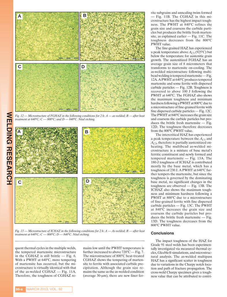
Fig. 11 — Microstructure of CGHAZ after heat treatment at the followingfor 2 h: A — 640°C; B — 800°C; C — 840°C. Nital etching.
A B
C
SILWAL ET AL SUPPLEMENT MARCH 2013layout_Layout 1 2/15/13 2:05 PM Page 85
MARCH 2013, VOL. 9286-s
WE
LD
ING
RE
SE
AR
CH
quent thermal cycles in the multiple welds,the tempered martensite microstructurein the CGHAZ is still brittle — Fig. 6.With a PWHT at 640°C, more temperingof martensite has occurred, but the mi-crostructure is virtually identical with thatof the as-welded CGHAZ — Fig. 11A.Therefore, the toughness of CGHAZ re-
mains low until the PWHT temperature isfurther increased to above 720°C — Fig. 7.The microstructure of 800°C heat-treatedCGHAZ shows the tempering of marten-site to ferrite with associated carbide pre-cipitation. Although the grain size re-mains the same as the as-welded condition(average 30-μm), there are new finer fer-
rite subgrains and annealing twins formed— Fig. 11B. The CGHAZ in this mi-crostructure has the highest impact tough-ness. The PWHT at 840°C refines thegrain size and coarsens the carbide parti-cles but produces the brittle fresh marten-site, as explained earlier — Fig. 11C. Thetoughness decreases from the 800°CPWHT value.
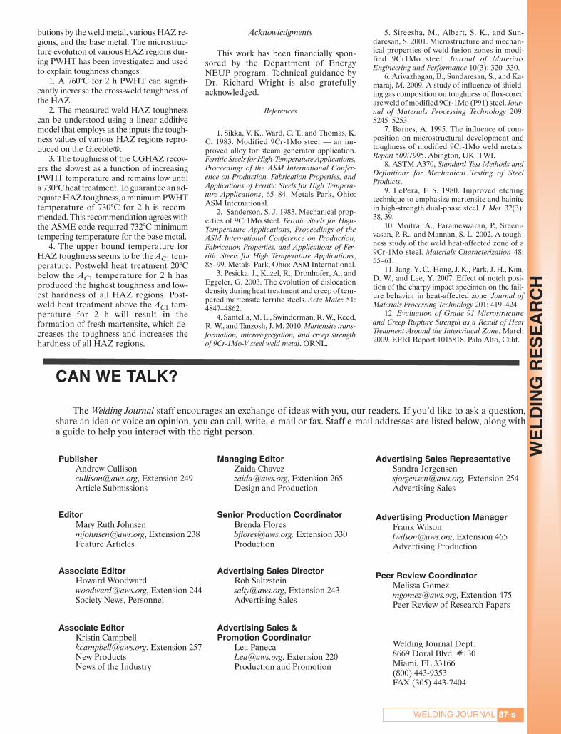
The fine-grained HAZ has experienceda peak temperature above AC3 (925°C) butbelow the temperature for austenitic graingrowth. The austenitized FGHAZ has anaverage grain size of 8 micrometers thattransforms to martensite on-cooling. Theas-welded microstructure following multi-bead welding is tempered martensite — Fig.12A. A PWHT at 640°C produces temperedmartensite and some ferrite with dispersedcarbide particles — Fig. 12B. Toughness isrecovered to above 100 J following thePWHT at 640°C. The FGHAZ also showsthe maximum toughness and minimumhardness following a PWHT at 800°C due toa microstructure of fine-grained ferrite withfine dispersed carbide particles — Fig. 12C.The PWHT at 840°C increases the grain sizeand coarsens the carbide particles but pro-duces the brittle fresh martensite — Fig.12D. The toughness therefore decreasesfrom the 800°C PWHT value.
The intercritical HAZ has experienceda peak temperature between the AC1 andAC3, therefore is partially austenitized on-heating. The multibead as-welded mi-crostructure is a mixture of base metal’sferritic constituent and newly formed andtempered martensite — Fig. 13A. The180-J toughness of ICHAZ is contributedmostly by the base metal, which has atoughness of 230 J. A PWHT at 640°C fur-ther tempers the martensite, but since thetoughness is governed by the dominatingbase metal, no significant changes in thetoughness are observed — Fig. 13B. TheICHAZ also shows the maximum tough-ness and minimum hardness following aPWHT at 800°C due to a microstructureof fine-grained ferrite with fine dispersedcarbide particles — Fig. 13C. The PWHTat 840°C increases the grain size andcoarsens the carbide particles but pro-duces the brittle fresh martensite — Fig.13D. The toughness decreases from the800°C PWHT value.
Conclusions
The impact toughness of the HAZ forGrade 91 steel welds has been experimen-tally investigated via measured thermal cy-cles, Gleeble® simulations, and microstruc-tural analysis. The as-welded multipassHAZ has a significant scatter in toughnessdue to variations in the Charpy notch loca-tion and path of fracture propagation. Thecross-weld Charpy specimen gives a tough-ness value that can be attributed to contri-
C D
B
Fig. 13 — Microstructure of ICHAZ in the following conditions for 2 h: A — As-welded; B — after heattreatment at 640°C; C — 800°C; D — 840°C. Nital etching.
Fig. 12 — Microstructure of FGHAZ in the following conditions for 2 h: A — as-welded; B — after heattreatment at 640°C; C — 800°C; and D — 840°C. Nital etching.
A
C
A
D
B
SILWAL ET AL SUPPLEMENT MARCH 2013layout_Layout 1 2/14/13 4:39 PM Page 86
87-sWELDING JOURNAL
WE
LD
ING
RE
SE
AR
CH
butions by the weld metal, various HAZ re-gions, and the base metal. The microstruc-ture evolution of various HAZ regions dur-ing PWHT has been investigated and usedto explain toughness changes.
1. A 760°C for 2 h PWHT can signifi-cantly increase the cross-weld toughness ofthe HAZ.
2. The measured weld HAZ toughnesscan be understood using a linear additivemodel that employs as the inputs the tough-ness values of various HAZ regions repro-duced on the Gleeble®.
3. The toughness of the CGHAZ recov-ers the slowest as a function of increasingPWHT temperature and remains low untila 730°C heat treatment. To guarantee an ad-equate HAZ toughness, a minimum PWHTtemperature of 730°C for 2 h is recom-mended. This recommendation agrees withthe ASME code required 732°C minimumtempering temperature for the base metal.
4. The upper bound temperature forHAZ toughness seems to be the AC1 tem-perature. Postweld heat treatment 20°Cbelow the AC1 temperature for 2 h hasproduced the highest toughness and low-est hardness of all HAZ regions. Post-weld heat treatment above the AC1 tem-perature for 2 h will result in theformation of fresh martensite, which de-creases the toughness and increases thehardness of all HAZ regions.
Acknowledgments
This work has been financially spon-sored by the Department of EnergyNEUP program. Technical guidance byDr. Richard Wright is also gratefully acknowledged.
References
1. Sikka, V. K., Ward, C. T., and Thomas, K.C. 1983. Modified 9Cr-1Mo steel — an im-proved alloy for steam generator application.Ferritic Steels for High-Temperature Applications,Proceedings of the ASM International Confer-ence on Production, Fabrication Properties, andApplications of Ferritic Steels for High Tempera-ture Applications, 65–84. Metals Park, Ohio:ASM International.
2. Sanderson, S. J. 1983. Mechanical prop-erties of 9Cr1Mo steel. Ferritic Steels for High-Temperature Applications, Proceedings of theASM International Conference on Production,Fabrication Properties, and Applications of Fer-ritic Steels for High Temperature Applications,85–99. Metals Park, Ohio: ASM International.
3. Pesicka, J., Kuzel, R., Dronhofer, A., andEggeler, G. 2003. The evolution of dislocationdensity during heat treatment and creep of tem-pered martensite ferritic steels. Acta Mater. 51:4847–4862.
4. Santella, M. L., Swinderman, R. W., Reed,R. W., and Tanzosh, J. M. 2010. Martensite trans-formation, microsegregation, and creep strengthof 9Cr-1Mo-V steel weld metal. ORNL.
5. Sireesha, M., Albert, S. K., and Sun-daresan, S. 2001. Microstructure and mechan-ical properties of weld fusion zones in modi-fied 9Cr1Mo steel. Journal of MaterialsEngineering and Performance 10(3): 320–330.
6. Arivazhagan, B., Sundaresan, S., and Ka-maraj, M. 2009. A study of influence of shield-ing gas composition on toughness of flux-coredarc weld of modified 9Cr-1Mo (P91) steel. Jour-nal of Materials Processing Technology 209:5245–5253.
7. Barnes, A. 1995. The influence of com-position on microstructural development andtoughness of modified 9Cr-1Mo weld metals.Report 509/1995. Abington, UK: TWI.
8. ASTM A370, Standard Test Methods andDefinitions for Mechanical Testing of Steel Products.
9. LePera, F. S. 1980. Improved etchingtechnique to emphasize martensite and bainitein high-strength dual-phase steel. J. Met. 32(3):38, 39.
10. Moitra, A., Parameswaran, P., Sreeni-vasan, P. R., and Mannan, S. L. 2002. A tough-ness study of the weld heat-affected zone of a9Cr-1Mo steel. Materials Characterization 48:55–61.
11. Jang, Y. C., Hong, J. K., Park, J. H., Kim,D. W., and Lee, Y. 2007. Effect of notch posi-tion of the charpy impact specimen on the fail-ure behavior in heat-affected zone. Journal ofMaterials Processing Technology 201: 419–424.
12. Evaluation of Grade 91 Microstructureand Creep Rupture Strength as a Result of HeatTreatment Around the Intercritical Zone. March2009. EPRI Report 1015818. Palo Alto, Calif.
CAN WE TALK?
The Welding Journal staff encourages an exchange of ideas with you, our readers. If you’d like to ask a question,share an idea or voice an opinion, you can call, write, e-mail or fax. Staff e-mail addresses are listed below, along witha guide to help you interact with the right person.
PublisherAndrew Cullison [email protected], Extension 249Article Submissions
EditorMary Ruth [email protected], Extension 238Feature Articles
Associate Editor Howard [email protected], Extension 244Society News, Personnel
Associate Editor Kristin [email protected], Extension 257New ProductsNews of the Industry
Managing Editor Zaida [email protected], Extension 265Design and Production
Senior Production CoordinatorBrenda [email protected], Extension 330Production
Advertising Sales Director Rob Saltzstein [email protected], Extension 243Advertising Sales
Advertising Sales & Promotion Coordinator
Lea [email protected], Extension 220Production and Promotion
Advertising Sales RepresentativeSandra [email protected], Extension 254Advertising Sales
Advertising Production Manager Frank [email protected], Extension 465Advertising Production
Peer Review Coordinator Melissa [email protected], Extension 475Peer Review of Research Papers
Welding Journal Dept. 8669 Doral Blvd. #130Miami, FL 33166 (800) 443-9353FAX (305) 443-7404
SILWAL ET AL SUPPLEMENT MARCH 2013layout_Layout 1 2/15/13 2:08 PM Page 87