fpga implementation of reed solomon codec for 40gbps
TRANSCRIPT

Rochester Institute of Technology Rochester Institute of Technology
RIT Scholar Works RIT Scholar Works
Theses
2-2006
FPGA implementation of Reed Solomon codec for 40Gbps FPGA implementation of Reed Solomon codec for 40Gbps
Forward Error Correction in optical networks Forward Error Correction in optical networks
Kenny Chung Chung Wai
Follow this and additional works at: https://scholarworks.rit.edu/theses
Recommended Citation Recommended Citation Wai, Kenny Chung Chung, "FPGA implementation of Reed Solomon codec for 40Gbps Forward Error Correction in optical networks" (2006). Thesis. Rochester Institute of Technology. Accessed from
This Thesis is brought to you for free and open access by RIT Scholar Works. It has been accepted for inclusion in Theses by an authorized administrator of RIT Scholar Works. For more information, please contact [email protected].

FPGA implementation of Reed Solomon Codec for
40Gbps Forward Error Correction in Optical Networks
by
Kenny Chung Chung Wai
A Thesis Submitted in Partial Fulfillment of the Requirements for the Degree of Master of Science in Computer Engineering
Approved By:
Supervised by
Assistant Professor Dr. Shanchieh Jay Yang Department of Computer Engineering Kate Gleason College of Engineering
Rochester Institute of Technology Rochester, New York
Feb 2006
Shanchieh Jay Yang Dr. Shanchieh Jay Yang Assistant Professor, Department of Computer Engineering Primary Adviser
Marcin Lukowiak Dr. Marcin Lukowiak Visiting Assistant Professor, Department of Computer Engineering
Doug Bush Doug Bush Director of IP Development, Xelic Inc.
Mark Garbosky Mark Grabosky Director of Design Methodology, Xelic Inc.

Thesis Release Permission Form
Rochester Institute of Technology
Kate Gleason College of Engineering
Title: FPGA implementation of Reed Solomon Codec for 40Gbps For
ward Error Correction in Optical Networks
I, Kenny Chung Chung Wai, hereby grant permission to the Wallace Memorial Library
reproduce my thesis in whole or part.
Kenny Chung Chung Wai Kenny Chung Chung Wai
Date

Dedication
I would like to dedicate this thesis to my parents, my brother's and my sister's family.
in

Acknowledgments
I would like to acknowledge Dr. Yang for his guidance and mentoring, Mr. Grabosky,Mr.
Bush and Dr. Lukowiak for serving as advisors on the thesis committee. I would also like
to thank Xelic Inc., relatives and friends for their support.
iv
Abstract
Reed-Solomon error correcting codes (RS codes) are widely used in communication and
data storage systems to recover data from possible errors that occur during data transfer.
A growing application ofRS codes is Forward Error Correction (FEC) in the Optical Net
work (OTN G.709), which uses RS(255,239) to support theOTU-3 (43 .0 1 8Gbps) standard.
There have been considerable efforts in the area ofRS architecture for ASIC implementa
tion. However, there appears to be little reported work on efficient RS codec (encoder and
decoder) for Field Programmable Gate Arrays (FPGAs), which has increasing interests in
industry.
This thesis investigates the implementation and designmethodology oftheRS(255,239)
codec on FPGAs. A portable VHDL code is developed and synthesized for Xilinx's Vir-
tex4 and Altera's StratixII. The FPGA architectures are analyzed and the required design
methodologies are adopted to efficiently utilize the available resources. Unfortunately, due
to the fixed size ofFPGA devices, the RS decoder is not only constrained by the required
timing of the system, but also by the size of the targeted device. This research will facil
itate the decision-making process for selecting a reconfigurable device for a RS decoder,
implementing the Berlekamp-Massey Algorithm.

Contents
Dedication iii
Acknowledgments iv
Abstract v
1 Introduction 1
1.1 Background 2
1.1.1 Forward Error Correction (FEC) methods 2
1.1.2 OTNG.709 3
1.1.3 Reed-Solomon Codes 5
1.1.4 ASIC vs FPGA 7
1 .2 Thesis Contribution 8
2 Reed-Solomon 10
2.1 What is a Reed-Solomon(RS) code? 10
2.2 How does RS code work? 11
2.2.1 Encoder 12
2.2.2 Decoder 14
2.3 Algorithm Analysis 17
2.3.1 GZP's algorithm 18
2.3.2 Example: Decoding RS(7,3) using GZP Algorithm 21
2.3.3 Berlekamp-MasseyAlgorithm 24
2.3.4 Example: Decoding RS(7,3) using BM Algorithm 24
2.3.5 Euclidean Algorithm 27
2.3.6 Example: Decoding RS(7,3) using Euclidean Algorithm 27
2.4 Implementation Issues 30
3 Design & Implementation 32
3.1 Encoder 33
vi

3.2 Decoder 34
3.2.1 Syndrome Calculator 35
3.2.2 Key Equation Solver 36
3.2.3 Error Locator 40
3.2.4 Error Evaluator 41
3.3 Summary 42
4 Simulation & Synthesis Results 44
4.1 Verification 44
4.1.1 MATLABModel 44
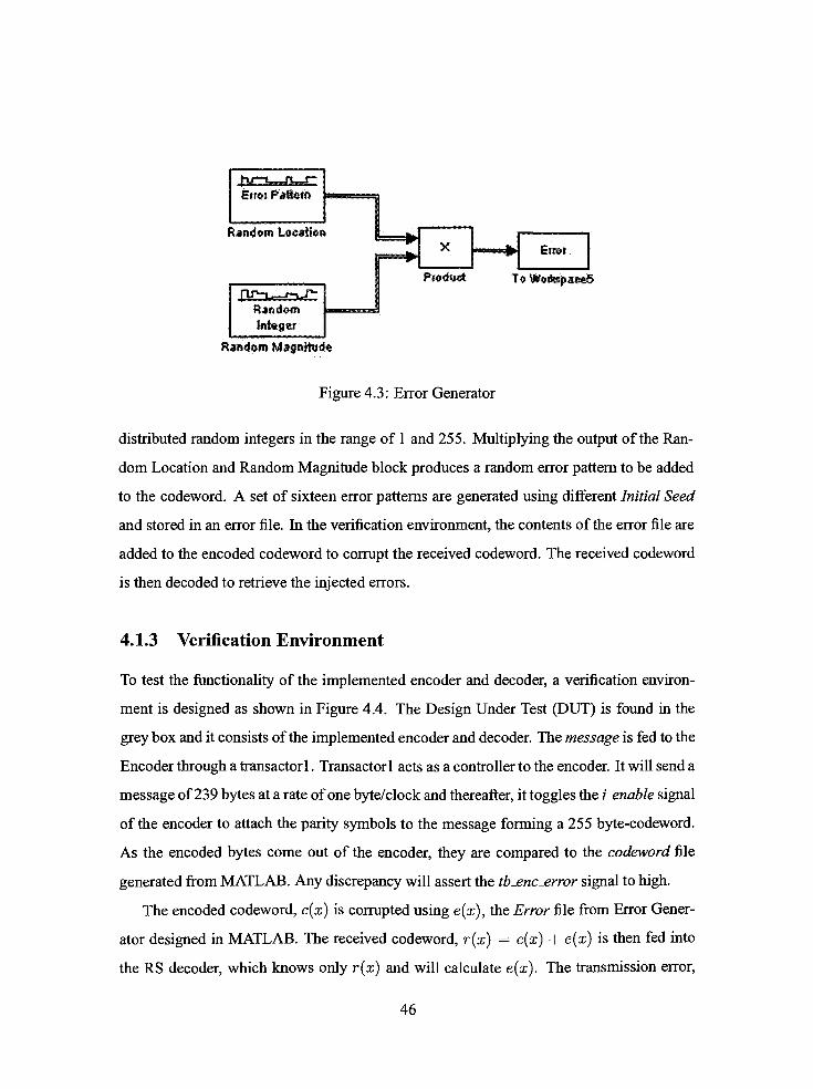
4.1.2 Error Generator 45
4.1.3 Verification Environment 46
4.1.4 Simulation Results 47
4.1.5 Post-Synthesis Simulation 50
4.2 Synthesis Results 52
4.2.1 Device Selection 53
4.2.2 Resource utilization by individual decoding block 56
4.2.3 Benchmark 57
5 Conclusion & FutureWork 60
Bibliography 62
vn

List of Figures
1 . 1 Forward Error Correction Concept 2
1.2 OTUk Frame Structure 3
1.3 OTUk based on ODUk and FEC [27] 4
2.1 the structure of a RS codeword 10
2.2 Different Decoding Techniques for Reed-Solomon codes [28] 14
2.3 Decoding scheme to be implemented in OTN G.709 15
2.4 Berlekamp-Massey Algorithm [4] 25
2.5 Euclidean Algorithm 28
3.1 System Block Diagram 32
3.2 EncoderBlock Diagram 33
3.3 EncoderArchitecture 33
3.4 DecoderBlock Diagram 34
3.5 Syndrome Calculator Block Diagram 35
3.6 Syndrome CalculatorArchitecture 36
3.7 Key Equation Solver Block Diagram 36
3.8 Berlekamp-Massey State Diagram 37
3.9 Proposed Berlekamp-Massey State Diagram 38
3.10 Error LocatorBlock Diagram 40
3.11 Error LocatorArchitecture 41
3.12 Error Evaluator Block Diagram 41
3.13 Error EvaluatorArchitecture 42
4.1 RSModel 44
4.2 Validation ofRS Codec model 45
4.3 Error Generator 46
4.4 System Verification Environment 47
4.5 Full Range Simulation 48
4.6 First Input Byte 49
vm

4.7 First Decoded Byte 50
4.8 Burst Error 51
4.9 Altera Post-Synthesis Simulation 51
4.10 Xilinx Post-Synthesis Simulation 52
4.11 CoreWrapper 53
4.12 Synthesis ofRS decoder on StratixII 54
4.13 Synthesis ofRS decoder on Virtex4 55
4.14 Relative Functional Block Utilization 56
4.15 Altera's vs Proposed Decoder 57
4.16 Xilinx's vs Proposed Decoder 58
IX
List of Tables
2.1 Galois field, GF(8), with p(z) =z3
+ z + l 11
2.2 Term Definition 12
2.3 Berlekamp-Massey Table 26
2.4 Euclidean's Algorithm Table 29
2.5 Comparison ofHardware Complexity and Path Delays [31] 30

Chapter 1
Introduction
The use and demand for optical communications have grown tremendously for applications
transmitting voice, data or video over short and long haul distances. The high bandwidth
requirements spawn the introduction of an Optical TransportNetwork (OTN) protocol, de
fined in the ITU-T G.709 specification [33]. This protocol describes three interfaces: OTU-
1, OTU-2 and OTU-3 at rates of2.666 Gbps, 10.709 Gbps and 43.018 Gbps, respectively.
Reed-Solomon (RS) Forward Error Correction (FEC) is included as part of the standard to
increase reliability by correcting errors thatmay be introduced. There have been consider
able efforts [28] [31] [15] in optimizing RS architectures for ASIC implementation based
on the Euclidean [32] and Berlekamp-Massey algorithm [5]. However, it is unclear if the
performance ofRS codecs on ASICs can be obtained on FPGAs since there is relatively
little work on how to optimize RS codecs for FPGA.
The two leading FGPAmanufacturers, Xilinx and Altera, provide their own versions of
RS codec targeting their devices. Xilinx uses the Euclidean algorithm whereas Altera uses
the Berlekamp-Massey algorithm to implement the Key Equation [4]. It is unclear why
they implemented different decoding algorithms and how the FPGA architectures affect
the implementation since the implementation is not in the public domain.
The goal of this thesis was to develop a generic VHDL model of the Reed-Solomon
codec that can be synthesized to Xilinx's Virtex4[30] and Altera 's StratixII[23]. The RS
codec was optimized to operate at the required speed ofOTU-3. The performance of the
RS codec on Virtex4 and StratixII was measured and compared to explore the impact of
1

FPGA architecture on VHDL model of RS codec. This contribution will facilitate the
decision-making of choosing a reconfigurable device for a RS codec implementation.
1.1 Background
1.1.1 Forward Error Correction (FEC) methods
More than 80% of the world's long distance and data transfer is carried over fiber optics,
ranging from global networks to desktop computers. To maintain the reliability of the
data traveling at high speed, various Forward Error Correction (FEC) techniques have been
proposed to correct errors introduced through transmitting over a noisy channel. Prior
to transmission, the FEC encoder introduces redundancy to the data. On receiving, the
receiver will detect and correct up to amaximum number oferrors, and such limit depends
on the algorithm used. The general concept of FEC is illustrated in Figure 1.1. FEC
FECTX
KRX Received^ FEC
Decoder
Ttwanitted NStey \ Recovered
Data__$
/
Figure 1.1: Forward Error Correction Concept
algorithms can be categorized into two main groups:
Convolution Coding
A convolution code is a type of error-correction codes in which an entire stream of
data is divided into fixed-size symbols, each containing m bits. Using a predeter
mined algorithm, k consecutive symbols are encoded to form a codeword of n bits
where n>m. Therefore, each codeword depends on k previous symbols. The code
words are also concatenated to form a continuous and theoretically infinite stream of
code symbols. This is one of the main reasons for using convolutional code in radio
and satellite communications [8]. A commonly used convolutional code is based on
the Viterbi algorithm [34].

Block Coding
A block code is another type of error-correcting codes in which a stream of data
is divided into fixed-size blocks, each containing k information symbols of prede
termined size. Each block is encoded to form a codeword of size n symbols. A
codeword, therefore, contains k information symbols, appended with n k parity
symbols. Onewell-known block code is the ubiquitous Reed-Solomon codes, widely
used in many applications for data storage and data transfer [36].
In 1993, Berrou, Glavieux and Thitimajshima introduced the Turbo codes [2]. This
high-performance error-correcting code operates to within 0.7dB of Shannon's limit [12],
which is the theoretical maximum information transfer rate of a channel. It uses two or
more convolution codes and an interleaver to produce a block code. Despite the high band
width efficiency of Turbo codes, RS codes are still widely used in applications such as
Asynchronous Transfer Mode (ATM) networks and Optical network (OTN)[33]
1.1.2 OTN G.709
A growing application of the RS code, specificallyRS(255,239), is for FEC in OTN G.709
[20] because of its relatively high error correction capability and low error burst sensitivity.
The OTN G.709 is an optical network protocol that provides higher backbone bandwidth.
The OTN frame structure can be referred to as Optical channel Transport Unit (OTUk)
Columns: 1 15 17
Rows: 1 i -.,;,
ODU
OH
O
p
o
H
4-
Payload
-ODUk-
3825 40SO
OTU
FEC
-OTUk-
Figure 1.2: OTUk Frame Structure

and is based on the Optical channel Data Unit (ODUk) frame structure appended with the
OTUk Forward Error Correction (FEC) as shown in Figure 1.2. The ODUk contains the
ODUk overhead area and the Optical channel Payload Unit (OPUk), and the FEC contains
parity symbols. The OTUk frame structure contains four rows and each row is made by
interleaving 16 RS(255,239) codewords as shown in Figure 1.3. Ifno FEC is used, all the
Ovh*ad
SC55. 2}
-^K-
Paviad
40SO
X
FEC
Figure 1.3: OTUk based on ODUk and FEC [27]
4 x 256 bytes in OTUk FEC section are set to zero. Three standard rates are defined in the
OTN G.709 specification [20]:
OTU-1: 2.666 Gbit/s
OTU-2: 10.709 Gbit/s
OTU-3: 43.018 Gbit/s
Currently, the OTU-1 and OTU-2 are primarily used to transparently carry Synchronous
Optical Network (SONET) frames, Ethernet frames, etc. However, the structures support
ing the OTU-3 rate have not been fully released. The OTU-3 standard has a serial transfer
rate of 43.018 Gbit/s. To achieve this rate, a data bus of 32 x 8 bit wide is typically used
with clock speed of 168.05 MHz.

1.1.3 Reed-Solomon Codes
The class of RS codes is a subclass of the Bose-Chaudhuri-Hocquenghem (BCH) codes,
discovered in the late 50s [4]. The class ofBCH codes belongs to the block codes fam
ily and is able to correct multiple error correcting codes. The BCH codes can be divided
into two subclasses: binary BCH and Reed-Solomon codes. In 1960, two members of the
MIT Lincoln Lab, Irving S. Reed and Gustave Solomon, published a seminar paper [29]
and marked the beginning of the RS codes. The seminar paper essentially showed that
a vector space ofm dimension can be mapped over a finite field K into a vector space of
higher dimension n over the same field, and assumingnomore than (n m)/2 errors occur
during transmission in the vector space of dimension n, there exists a decoding procedure
which recovers the errors completely. In 1963, Peterson, Gorenstein and Zierler (PGZ)
presented the first algorithm that explicitly described a decoding algorithm [35] of the RS
codes. PGZ's decoding algorithm, however, as the was limited by the size of the codeword
because of the matrix inversions needed to calculate the locations and the magnitudes of
the errors. By the end of the 60s, Berlekamp [1] andMassey [26] combined their effort to
provide the Berlekamp-Massey (BM) algorithm, the first efficient algorithm to decode the
RS codes. Instead of computingmatrix inversion, the Berlekamp-Massey (BM) algorithm
solved a "KeyEquation"
to locate and evaluate the errors. In 1975, Sugiyama [32] proved
that the traditional Euclidean algorithm could also be used to solve the "KeyEquation,"
thus decoding BCH and Reed-Solomon codes. In 1995, Fitzpatrick [9] introduced a new
decoding algorithm and claimed that his algorithm utilized fewer finite field multipliers
than the Berlekamp-Massey 's algorithm. A year later, in 1996, Blackburn and Chambers
[3] pointed out a flaw in the claim made by Fitzpatrick. After analyzing both algorithms,
they found out that the version ofBerlekamp-Massey algorithm that Fitzpatrick had used
to benchmark against his algorithm was not themost efficient implementation. After com
paring the complexity of both algorithm, they concluded that Fitzpatrick 's algorithm was
as efficient as the BM's algorithm. The BM and the Euclidean algorithm are the two most
commonly-used decoding algorithms for RS codes.

TheBerlekamp-Massey algorithm is an efficientmethod in decoding the Reed-Solomon
codes [5]. Consequently, much research has been done to optimize for implementation.
Sarwate [31] proposed a high-speed architecture in which a single array ofprocessors are
used to compute both the error-locator and the error-evaluator polynomials. Sarwate's ar
chitecture required approximately 25% fewer multipliers and a simpler control structure
than the architecture based on the Euclidean algorithm. Raghupathy [28] modified the BM
decoding algorithm to not only increase the speed, but also obtain a low-power architecture.
The results ofhis implementation indicated a power reduction ofabout 40% and a speed-up
of 1 .34 compared to a normal design without his proposed modifications. Another way to
improve the speed of the BM algorithm was to use the"division-free"
algorithm, proposed
by Dinh [7]. To verify the functionality of the decoder, Dinh compiled his HDL code to an
Altera FPGA device, EPF10K200A. The designed decoder occupied 12,745 logic cells and
operated at 12MHz. When synthesized using a 0.18/x CMOS technology, the same design
operated at the clock speed ranging between 125MHz to 250MHz.
Similar to the BM algorithm, optimized architecture and implementation of the Euclid
ean algorithm have also been the subjects for a number of research papers. A lot of effort
has been invested to improve the architecture of the Euclidean algorithm. Lee has been a
major contributor to the evolution ofRS decoding based on theEuclidean algorithm [16]. In
2001, he proposed a high speed design of the Reed-Solomon decoder [15] using a modified
version of the Euclidean algorithm. In 2003, he implemented an area-efficient Euclidean
Block for Reed-Solomon decoder [17] which targeted on the 0.13yu CMOS technology. In
the same year, Lee and Azam presented a novel pipelined recursive modified Euclidean
algorithm block for a low-complexity, high-speed RS decoder [19].
All of the afore-mentioned works on both the BM and the Euclidean algorithm were
targeted to CMOS technologies. Among the few papers discussing implementations of the
RS codec on reconfigurable devices, Flocke [10] introduced a highly parameterizableRS-
decoder for FPGAs in 2005. His implementation, based on the inversionless Berlekamp
Algorithm, was tested on Altera APEX 20KE device and achieved a high throughput rate

of 1 .3 Gbit/s. A case study [13] about using the run-time reconfigurability (pRTR) feature
available on VIRTEX FPGAs was published in 2002. The author referred to the design
of a RS decoder as an example to go over the methodology and design flow for VIRTEX
FPGAs which enabled the user to implement large designs into a moderately sized FPGA.
Unfortunately, none of these research reported which decoding algorithm is appropriate in
decoding RS codes for FPGA devices.
1.1.4 ASIC vs FPGA
FPGA, Field Programmable Gate Array, denotes an integrated circuit that is configured
in the field, whereas ASIC, Application Specific Integrated Circuit, denotes an integrated
circuit that is fully customized to the requirements of a given application. Before mak
ing a choice between ASIC and FPGA for a specific design, several parameters must be
considered.
FPGA has become very popular in industry because of its short development time.
FPGAs are available off-the-shelfwhereas forASICs, a typical lead time between eight to
sixteen weeks is needed to get the design out of the factory. The designers who use FPGAs
have the real silicon to test the implementation instead of testing through simulation only.
The FPGAs can be reconfigured as many times as needed during development. There is no
NRE cost for FPGA, but the unit cost ofone FPGA is higher than that ofASIC. Depending
on the production volume, ASIC designmay still be chosen overFPGA because ofthe high
yield ofan optimized architecture.
Designing in ASIC and FPGA requires different design methodologies. Designing for
ASICs, the designer needs to focus on how to optimize the architecture ofthe system so that
it consumes the least area and runs at the required speed. Whereas designing for FPGAs,
not only the designer needs to focus on optimizing the system, but he also needs to under
stand the architecture of the chosen FPGA device so that he can make use of the available
resources and efficiently utilize these resources. SinceASIC and FPGA are completely two
different technologies, a design created for an ASIC may not work well on an FPGA. Most

works in the field ofRS decoder are targeted to ASIC and there is no related work on how
the algorithms used RS decoder are dependent on FPGA architectures. Altera and Xilinx
are two main FPGA manufacturers and it is a known fact that FPGA architecture is spe
cific to vendors. Because of the difference in architecture, it is hard to predict the physical
behavior of the RS codec from one FPGA family to another. Both companies mentioned
above have their Intellectual Property (IP) cores for RS codec. However, Xilinx imple
ments the Euclidean algorithm, and Altera implements the Berlekamp-Massey algorithm
for their RS decoders.
1.2 Thesis Contribution
The goal of this thesis workwas to investigate the effect ofFPGA architecture on RS codec
implementation. A portable Reed-Solomon codec was designed in VHDL and its perfor
mancewas measured onXilinx's Virtex4 [30] andAltera's StratixII [23]. The implemented
RS codes was specified byRS(255, 239), used for error correction in OTN G.709 [33]. The
resource utilization and speed of the two FPGA devices were the targeted performance
metrics for the analysis.
One dominant factor which limits the performance of the decoder is the architectural
features of the FPGAs. The VHDL code was compiled toward both the Virtex4 and
StratixII FPGA families, and the synthesis results lead to a better understanding of the
impact of FPGA architecture on RS codec performance. The performance of the imple
mented codec achieved the required speed to implement FEC in OTU-3. However, such
result did not repeat itself on Xilinx's Virtex4. It was found that Altera's architecture fa
vors Berlekamp-Massey's algorithm to solve the key equation. Research and development
is underway to confirm the performance ofEuclidean's algorithm on Xilinx's Virtex4.
This thesis is organized as follows. Chapter 2 describes the Reed-Solomon codes and
different algorithms of the Reed-Solomon decoders. Chapter 3 describes the design and
implementation of the generic Reed-Solomon decoder. The results of the implementation

are presented and analyzed in Chapter 4. Chapter 5 will conclude the thesis and highlight
the plans for future work.

Chapter 2
Reed-Solomon
2.1 What is a Reed-Solomon(RS) code?
AReed-Solomon code [29] is themapping from a vector space ofm dimension over a finite
fieldK into a vector space ofhigher dimension n over the same field, and assuming no more
than (n m)/2 errors occur during transmission in the vector space of dimension n, there
exists a decoding procedure which recovers the errors completely. A Reed-Solomon code
is a block code and is specified as RS(n,k) as shown in Figure 2. 1 . n defines the size of the
k 2t
DATA PARITY
jr?
Figure 2. 1 : the structure ofa RS codeword
codeword in the unit of symbols, k is the number of data symbols and 2t n k is the
number ofparity symbols. Each symbol contains s bits, where
s = log2{n + _)oin= 1 (2.1)
The relationship implies that the use of s-bit symbols allows for a maximum of2s
1
distinct symbols in one codeword, excluding the one with all zeros. The maximum number
of symbol errors that the RS code can correct is given by t, half the size of the parity. For
10

example, consider RS(255,239) defined for the optical network specification, OTN G.709
[33]. The size n is 255 symbols, the number of data symbols k is 239 symbols. The
maximum number of symbol errors that RS(255,239) decoder can correct is, therefore, 8
symbols, where each symbol contains 8 bits.
2.2 How does RS code work?
The Reed-Solomon code is defined in the Galois field [4]. A Galois field is a finite field
that contains a set ofnonzero elements forming a cyclic group under multiplication. Each
nonzero element can be expressed as a power ofa primitive element, a, of the field.
The Galois field GF(2S) is constructed based on a primitive polynomial, p{z), which
determines the pattern of the sequence. For example, consider the RS(7,3) with the primi
tive polynomial p(z)=
z3
+ z + 1. n is 7 and each symbol contains log2(n + 1) = 3 bits.
A Galois field, GF(23), with the specified primitive polynomial is constructed as shown in
Table 2.1.
Exponent Polynomial BinaryQ
1 001
a1
z 010
a2 z2
100
a3
z + 1 011
a4 z2
+z 110
a5 z2
+ z + 1 111
a6 z2
+ 1 101
a7
=a
1 001a8
=a1
z 010
Table 2.1: Galois field, GF(8),withp(z) =z3
+ z + 1
An addition of two elements in the Galois field is simply the exclusive-OR (XOR)
operation. For example
ab
+ab
={z2
+ z + 1){z2
+ 1)
,.i
z = a
11

However, amultiplication in the Galois field is more complex than the standard arithmetic.
It is the multiplicationmodulo the primitive polynomial p(z). For example,
a5 a6
=a5 a6
mod p(z)
=(z2
+ z +l)*(z2
+l)mod(z3
+ z + l)
=z2
+ z =a4
A stream of data 010 100 000 that needs to be transmitted over the channel can be
represented as a transmittedmessage polynomialm(x)(2.2).
m(x)=ax2
+ a2x. (2.2)
Table 2.2 defines the notation for the polynomials that will be used to explain the for
mation and decoding of the RS code in the following sections
Item Term Definition
c{x) transmitted codeword
m(x) transmittedmessage
9{x) generator polynomial
e{x) error polynomial
r(x) received codeword
S(x) syndrome polynomial
n(x) error evaluator polynomial
A(x) error locator polynomial
mQ a natural number
e number of errors
Table 2.2: Term Definition
2.2.1 Encoder
Encoding the RS code is basically mapping a message of dimension k into a codeword
of dimension n. The mapping is done using a generator polynomial (2.3) of dimension
_t . One encoding scheme is known as non-systematic encoding, which is a Galois Field
12

multiplication between the transmitted message and the generated polynomial as shown in
(2.3).
c(x)=
m(x)g(x) (2.3)
where g(x) is the generator polynomial ofdegree 2i and is given by
m0+2t-l
g{x)= J] (x + a*) (2.4)
i=mo
m0 is a natural number and defines the coefficients of the generator polynomial. The en
coded codeword contains the original message m(x) encrypted with g(x). This encoding
scheme is not very practical because at the receiving side, m(x) is recovered when dividing
c(x) by g{x) using polynomial long division,which requires additional computations.
An another encoding scheme was proposed and is known as systematic encoding as
shown in (2.5).
c(x)=m(x)X2t
+m{x)X2t
mod g{x) (2.5)
The transmitted codeword is encoded in a way that the transmittedmessage m(x) appear
as the first k symbols, appended with _t parity symbols. At the receiving side, themessage
m(x) is recovered by reading only the first k symbols.
Encoding Example
Themessage (2.2) is encodedwith the generator polynomial defined as
3
i=0
=x4
+a2x3
+a5x2
+ a5x +a6
m(x) is first shifted by four symbols to the left and the result is divided by g(x) as shown
below
m{x)X4
=ax6
+a2x5
m(x)X4
mod g(x)=
ax6
+a2x5
modx4
+a2x3
+a5'x2
+ a5x +a6
=a3x2
+ a5x + a
13

Using (2.5), the resulting codeword is then given as
c(x)=axb
+a2xb
+crx1
+ abx + a (2.6)
and can also be represented as 010 100 000 000 Oil 111 010 in binary. Af
ter decoding the received codeword, the transmitted stream of data is easily recovered by
extracting the first three symbols from the codeword.
2.2.2 Decoder
Figure 2.2 shows the multiple approaches to decode the received data as described by
Raghupathy and Liu[28]. A decoding algorithm is typically chosen according to a spe
cific application. A commonly used RS decoding scheme for the OTN G.709 is shown in
Figure 2.3, and because ofitswide acceptance, this thesisworkwill focus on implementing
this specific decoding scheme.
iSeoMl>a')
i -
[\
C*fcuUle
? '
> ftai&mi
'
fin*Error Locator
Enw Magnitude
-
BerisfcimpM__yMf,
pofywsisl 1Pbaatf-Q_va__a
Zierter Algorithm
Ttaitifortrt*d
i' '
B*rtkampAlf.\ FjrtwittonofE
Fri*S error
Magnitude paly. Aljgwtthro
TinwDoraaHi
Recursive
Estenitoo
1
? 1 1
'
1.OwnStandi
anwtoaMtofl
CHSsn Sthtct,
rarer loouiorj
< '
fenweFT
Traxvsfcnncd
Fornt-y''. mttx*i
? +Sefrve equations
lor -tic*valoei for errorvita
'' ? * 1 '
I
Figure 2.2: DifferentDecoding Techniques for Reed-Solomon codes [28]
14
**f, >
Key EtjusfSonSnivw
(EM'S
Algorithm)
KrjC&Hwd
Syixfcome
Cafcat&or
AW.-.Error
LOC35W
jCftlons
AlgorKhm)
l_^_^Error
Evaiuaar
iRsray's
A^arjUwi)
codeword=t
OBJ ;
M, ? .Ettt^Pitos***)..
wW) ^wsiaenr"/raoiMf '
; RSQ _
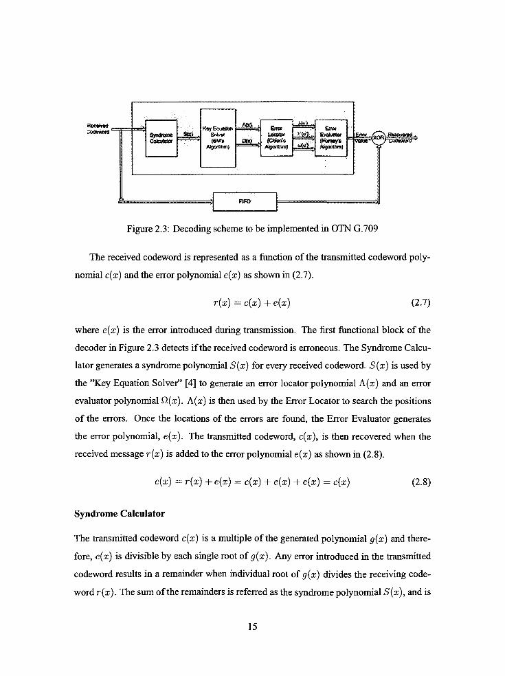
Figure 2.3: Decoding scheme to be implemented in OTN G.709
The received codeword is represented as a function of the transmitted codeword poly
nomial c(x) and the error polynomial e(x) as shown in (2.7).
r(x)=
c(x) + e(x) (2.7)
where e(x) is the error introduced during transmission. The first functional block of the
decoder in Figure 2.3 detects if the received codeword is erroneous. The Syndrome Calcu
lator generates a syndrome polynomial S(x) for every received codeword. S(x) is used by
the "Key EquationSolver"
[4] to generate an error locator polynomial A(x) and an error
evaluator polynomial fi(x). A(x) is then used by the Error Locator to search the positions
of the errors. Once the locations of the errors are found, the Error Evaluator generates
the error polynomial, e(x). The transmitted codeword, c(x), is then recovered when the
receivedmessage r(x) is added to the error polynomial e(x) as shown in (2.8).
c(x) r(x) + e(x)=
c(x) + e(x) + e(x)=
c(x) (2.8)
Syndrome Calculator
The transmitted codeword c(x) is a multiple of the generated polynomial g(x) and there
fore, c(x) is divisible by each single root ofg{x). Any error introduced in the transmitted
codeword results in a remainder when individual root of g(x) divides the receiving code
word r(x). The sum of the remainders is referred as the syndrome polynomial S(x), and is
15

defined in (2.9).m0+2t-l
S(x)= J^ r{ai),m0<i<m0 + 2t-l (2.9)
i=mo
If 5(x) = 0, the received codeword is error free. Otherwise, the syndrome polynomial is
processed by the Key Equation Solver functional block.
Key Equation Solver
The objective oftheKey Equation Solver is to solve an equation that describes the relation
ship between the syndrome polynomial S(x), the error locator polynomial, A(x), and the
error evaluator polynomial fi(x).
A(x)5(x) = tt(x) modx2t
(2.10)
where A(x) and Q(x) may be represented in the general form shown in (2.1 1) and (2.12),
respectively.
e
a(z) =n t1 ~
x^ = i + Xix +a2x2
+ - +Xexe
(2-1 j)j=l
e e
M(x) = Y_ YiXi J] (l -
Xix) = ^o + wis +uj2x2
+ ...+uje_xxe~^
(2.12)
The error locator polynomial, A(x), has a degree of e < t and has as its roots the
inverses of the e error locators {Xj}. The error evaluator polynomial, Q(x) has degree at
most e 1 to determine themagnitude ofe errors.
This is the most complex block to be designed and implemented. There are different
algorithms that have been used to implement this component. However,most ofthese algo
rithms are optimized only for ASIC design. In this thesis, two commonly used algorithms
are considered to implement the Key Equation block: the Berlekamp-Massey [4] and the
Euclidean [18]. These algorithms are discussed in Section 2.4.
16

Chien Search Error Location
The locations of the errors are determined based on the error locator polynomial (2.1 1).
Each aj form0 < j < mQ + It 1 is plugged into (2.1 1). IfA(aj) 0, the inverse ofaj
is calculated to be = ac, and the location of an error be indicated by the exponent c.
This process is known as the Chien search algorithm.
Forney's method for error values
In this block, the error evaluator polynomial Q(x) is computed to find the corresponding
error value at each error location. The output of this block is the error polynomial e(x)
which is a polynomial representing the value and location of the errors.
The syndrome Calculator, Chien's search [6] and Forney's method [11] are relatively
simple to implement compared to theKey Equation Solver. There exist different algorithms
to implement the Key Equation Solver as discussed in the following section.
2.3 Algorithm Analysis
In 1960, Peterson's algorithm was the first explicit description of a decoding algorithm for
binaryBCH codes. One year after, Gorenstein andZierler extrapolated Peterson's decoding
algorithm to illustrate the decoding scheme of theReed-Solomon codes. However, the GZP
decoding algorithm was limited by the size ofthe code because of the need formatrix inver
sions to calculate the error-locations andmagnitudes. Five years later, in 1965, marked the
introduction of the Berlekamp-Massey algorithm. The Berlekamp andMassey's approach
was to solve the "KeyEquation"
to locate and evaluate the errors. In 1975, it was proven
that the Euclidean algorithm can also be used to solve the "KeyEquation"
in decoding the
Reed-Solomon codes.
17
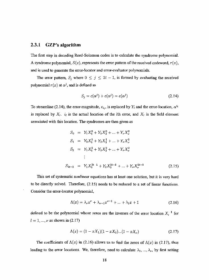
2.3.1 GZP's algorithm
The first step in decoding Reed-Solomon codes is to calculate the syndrome polynomial.
A syndrome polynomial, S(x), represents the error pattern of the received codeword, r(x),
and is used to generate the error-locator and error-evaluator polynomials.
The error pattern, Sj where 0 < j <_t 1, is formed by evaluating the received
polynomial r(x) at a? , and is defined as
S, = c(ct) + e(aj)=
e{aj) (2.14)
To streamline (2.14), the error-magnitude, eip is replaced by YJ and the error-location,aH
is replaced by Xt. i{ is the actual location of the Zth error, and XL is the field element
associated with this location. The syndromes are then given as
S0 = Y1X_+Y2X_+... +YX
Sx = Y_X\ + Y2Xl + ... +YXl
S2 =Y_X_+Y2X2
+ ... +YuX2
S2t-_ =Y_X2t~x
+Y2Xit~1
+ ... +YvXlt~1
(2.15)
This set of systematic nonlinear equations has at least one solution, but it is very hard
to be directly solved. Therefore, (2.15) needs to be reduced to a set of linear functions.
Consider the error-locator polynomial,
A(x) - AX +K-ix"'1
+ ... + Aix + 1 (2.16)
defined to be the polynomial whose zeros are the inverses of the error locationX^1
for
1 = 1, .., v as shown in (2.17)
A(x) = (1 -
xX_)(l-
xX2)...(l-
xX) (2.17)
The coefficients ofA(x) in (2.16) allows us to find the zeros ofA(x) in (2.17), thus
leading to the error locations. We, therefore, need to calculate A1; ..., Aj,, by first setting
18

(2.16) = (2.17). Then, both sides are multiplied byYJX/+*
', and x is replaced by Xl1to
give
Ytxl+V[i +x_xfx
+x2Xf2
+ ... +K-_x;("-1]
+AX1 = o
Yi[Xi+v
+X1Xi+v-1
+ ... + \vXi\ = 0 (2.18)
Since (2.18) is valid for each I, these equations are summed up from / = 1 to I = v,
giving for each j,
J2Yl[xj++\1xr-i+-+Kxi} = o
(=1
^y1x>+v+\i_>2y1x>+v-1
+ ... +\i,Y/y,x>
= 0
i=i
(2.19)i=i i=i
The individual sums are equivalent to the syndromes, and (2.19) can be expressed as
bj+v + \ibj+vi + ... + Xvbj 0
Al>->j+i/_l + X2bj+i_,_ + ... + Xvbj =bj+_, (2.20)
(2.20) is the set of linear equations relating the syndromes to the coefficients ofA(x)
and can be expressed in amatrix form as shown in (2.21).
So Si S2 ... Sv_2 S_y-l
Si S2 S3
S2 S3 S4
bv-l b_,
b_, Jy+l
1 Sv-i Sv Sv+\ ... S2v_3 S2v_2 J \ Xi I \S2l/_i j
1 k ^
Xv-i
Xv_2
(-sv
S+i
S_,+2
\
Let M be
Sq Si S2
Si S2 S3
S2 S3 04
bv-2 Sv-i
bvl bv
bv bv+l
\
i bv-l bv b_,_\_l ... b2v-3 S2u-2 j
19
(2.21)
(2.22)
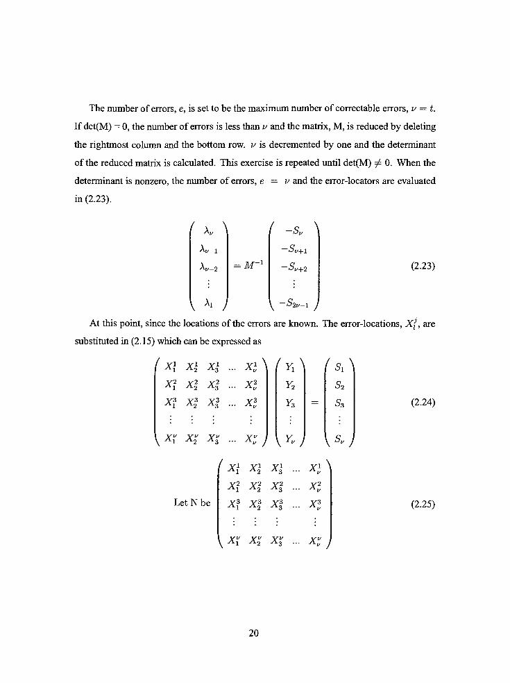
The number of errors, e, is set to be the maximum number of correctable errors, v= t.
If det(M) = 0, the number of errors is less than v and the matrix, M, is reduced by deleting
the rightmost column and the bottom row. v is decremented by one and the determinant
of the reduced matrix is calculated. This exercise is repeated until det(M) ^ 0. When the
determinant is nonzero, the number of errors, e = v and the error-locators are evaluated
in (2.23).
/ A \
Xv-1
Aj/-2
/_
=M~1
S
Sv+l
Su+2
\
(2.23)
\ Xi J y -s2v-i j
At this point, since the locations of the errors are known. The error-locations, Xf_ are
substituted in (2.15) which can be expressed as
( Xl XI Xl ... Xl\ ( Yi\ I Si \
y2 y2 y2 v2
Al A2 A3 - Av
XfX3 X3
... X3V
Yi
Y2
Y3
S2
S3
{ X_ Xv2 XI ... XI j \YV ) \SV )
(x\ x\ x\ ... xi\
Let N be
y2 v2 v2
Al A2 A3
y3 y3 y3
Al A2 A3
xi
xl
x3
\x_ x_ x% ... xi J
(2.24)
(2.25)
20

The error-magnitudes at specific location are determined as
'yA fsA
Y2
Y3AT1
S2
S3 (2.26)
V Yv J \SV)
Both the location and the magnitude of the errors have been resolved. The erroneous
message can now be corrected to obtain transmittedmessage.
2.3.2 Example: Decoding RS(7,3) using GZP Algorithm
After transmitting the codeword(2.6) through the noisy channel, let the received data be
r(x)=ax5
+ orx + ccx (2.27)
Calculating the error pattern, Sj, 0 < j < 3
S0 =
r(a)=a2
+a3
+a5
= 0
Si =
ria1)=a7
+a5
+a6
=a3
S2 =
r{a2)=a12
+a7
+a7
a
S3 =
r(a3)=a17
+a9
+a*
= a
The syndrome polynomial is then represented as
S(x) =abx3
+ a5x + a3x (2.28)
The next step is to derive the error-locator polynomial leading to the error locations.
With respect to (2.21), v is two and therefore:
(2.29)
21

where M0
a3
a3 a5
det(M)0
a3
a3 a5
(2.30)
0 +a6
=a6
Since det(M) ^ 0, the number oferror e = 2.
The error-locator polynomial is then represented as A(x) =A2x2
+ Ajx + 1, where A2
and Xx are then calculated as:
(2.31)
alu+aa
a"
a'-
The error locator polynomial is A(x) =a6x2
+ a2x + 1
The Chien's algorithm is used to calculate the location of the errors from the error-
locator polynomial, A(x)
a0)=
a6
+a2
+ 1 = 0
a1)=
a8
+a3
+ 1 = 0
a2)=
a10
+a4
+ 1 =a2
a3)=
a12
+a5
+ 1 = 1
(2.32)
(2.33)
22

A(a4) -a14
+ aXl =a6
A(a5) -a16
+a7
+ l =a2
A(a6) =q18
+a8
+ 1 =a6
The zeros of A(x) are Xi and X2 which are equivalent toa~
anda~l
respectively.
According to (2.17), the location of the errors given as position 0 and 6. The error-locations
are then substituted in the the syndrome set ofequation (2.28) giving
Si =
r(a1)=e6a6
+ e0 =a3
S2 =
r{a2)=e6a12
+ e0=a5
The above simultaneous equation can be expressed in matrix form
a3
a5
Therefore, = (2.34)
a
a3+a5
a
Q8+a"
a
The error polynomial is given by e(x) =ax6
+ a and the corrected message is:
c(x)=
r(x) + e(x)
=a2x5
+a3x2
+ a5x +ax6
+ a
=ax6
+a2x5
+a3x2
+ a5x + a (2.35)
The GPZ algorithm provides the basis of the Reed-Solomon decoder. However, this al
gorithm is limited in the number oferrors it can correct before the implementationbecomes
23
too computational intensive due to the matrix inversion. To efficiently correct large num
ber of errors, other approaches have been developed and among those are theBerlekamp-
Massey and the euclidean algorithm.
2.3.3 Berlekamp-Massey Algorithm
The Berlekamp-Massey algorithm was first introduced in 1965. It is the first efficient al
gorithm to decode the RS code. The Berlekamp and Massey's approach is to generate a
Linear Feedback Shift Register (LFSR) ofminimal length and with the required feedback
A such that the first It elements in the LFSR output sequence shall correspond to the syn
dromes Si, S2,..., S2tto satisfy (2.20). The taps of the LFSR represents the coefficients
of (2.16), which uniquely specifies the error-locator polynomial.
Figure 2.4 shows the flowchart oftheBerlekamp-MasseyAlgorithm. Once the Berlekamp-
Massey LFSR has been constmcted, the feedback taps represent the coefficients of the
error-locator polynomial. Having the error-locator polynomial A(x) and the Syndrome
polynomial S(x), the error-evaluator polynomial fi(x) is solved from the key equation
(2.36).
A(x)S(x) = Q(x) modx2t+l
(2.36)
Once the error-locator polynomial and the error-evaluator polynomial have been de
rived, the error locations and errormagnitudes are solved using the Chien's [6] and Forney's
[11] algorithm, respectively.
2.3.4 Example: Decoding RS(7,3) using BM Algorithm
The same set ofdata as in Example 2.3.2 is used. The received polynomial is given as
r(x)=a2x6
+a2x5
+ a5x + a (2.37)
and the previously calculated syndrome is expressed as
S(x) =a4x3
+a6x2
+ a2x +a6
(2.38)
24

Initializeifcm
1=0 BfrH
r^c+ 1
Compute trann rsexi syndrome
Does eumem s.Wft raster
design produce next syndroms?<X ^t = 07
Yw
Compute newoommMm polynwrtt fcrwhichA, =0
Muttshift ttsgistwbe
tengtisnfifl?
No
At*)*-m
B(x) *A,'
A{x) Normalizeand$tom
old shiftmgAlx)*-T(x) Update shtBusg-
L'-r-L Update length
Figure 2.4: Berlekamp-Massey Algorithm [4]
25

The error-locator polynomial is calculated using the flowchart in Figure 2.4. Table 2.3
shows the intermediate values of different variables at different iteration. The number of
iterations in this example is four because the RS code can correct up to two errors.
r Ar T(x) B(x) A(x) L
0 110
la61 + a6x a 1 + a6x 1
2a3
1 + a3xa4
+ a3x 1 + a3x 1
3 a 1 + a2x +a4x2 a6x2
1 + a2x +a4x2
2
4 1 1 + x +ax2 a6
+a2x2
1 + x +ax2
Table 2.3: Berlekamp-Massey Table
The resulting error-locator polynomial is A(x) = 1 + x + ax2. The error evaluator
polynomial is then calculated from the key equation:
fi(ar) = A(x)S(x) modx2t
=(ax2
+ x + 1)(a4x3
+a6x2
+ a2x + a6) modx4
= x +a6
(2.39)
Using the Chien's algorithm, the locations of the errors are searched
A(a) = 1 +a0
+a1
= 1
Aia1) = 1 +q1
+a3
= 0 (2.40)
A(a2) = l +a2
+ab
=a1
A(a3) = l +a3
+aXa3
A(a4) = l +a4
+a9
=a3
A(a5) = 1 +a5
+a11
= 0 (2.41)
A(a6) = l +a6
+a13
= l
The zeros ofA(x) are Xi and X5, which are equivalent toa-1
anda-5
respectively.
The location of the errors given as position 6 and 2.
26
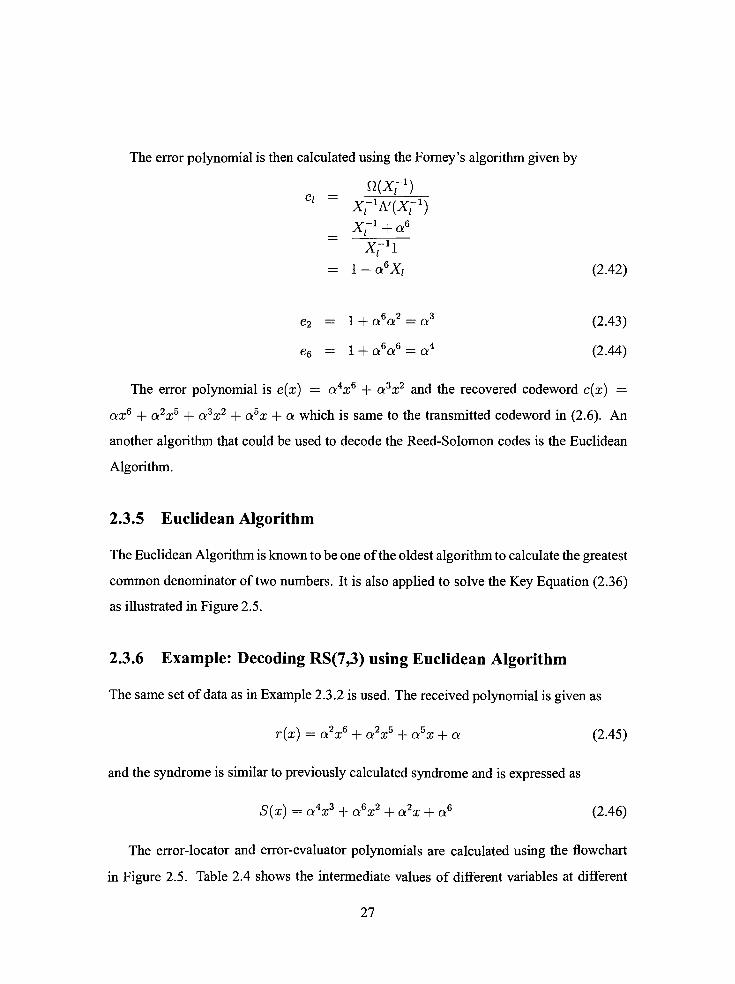
The error polynomial is then calculated using the Forney's algorithm given by
Q(X^)ei
X^A'iXf1)XJ1
+a6
X1!
= l + a6Xi
e2= l +
a6a2
=a3
e6= l +
a6a6
=a4
(2.42)
(2.43)
(2.44)
The error polynomial is e(x)=
a4x6
+a3x2
and the recovered codeword c(x)=
ax6
+a2x5
+a3x2
+ a5x + a which is same to the transmitted codeword in (2.6). An
another algorithm that could be used to decode the Reed-Solomon codes is the Euclidean
Algorithm.
2.3.5 Euclidean Algorithm
TheEuclideanAlgorithm is known to be one of the oldest algorithm to calculate the greatest
common denominator of two numbers. It is also applied to solve the Key Equation (2.36)
as illustrated in Figure 2.5.
2.3.6 Example: Decoding RS(7,3) using Euclidean Algorithm
The same set ofdata as in Example 2.3.2 is used. The received polynomial is given as
r{x)=a2x6
+a2x5
+ a5x + a (2.45)
and the syndrome is similar to previously calculated syndrome and is expressed as
S(x) =a4x3
+a6x2
+ a2x +a6
(2.46)
The error-locator and error-evaluator polynomials are calculated using the flowchart
in Figure 2.5. Table 2.4 shows the intermediate values of different variables at different
27

InWat&sitofi
if
i*-i+.1
IG6rripwfe the quofeni
d .fr>^i^
ICompute
AWA*ft) - A-ifxiQ^/xJ
Yes
Proceed to>
NextStep
No
Figure 2.5: Euclidean Algorithm
28

iteration. The number of iterations in this example is two because the RS code can correct
up to two errors.
The key equation is represented as
S(x)A(x) =ft(x)modx2t
S(x)Bi(x) =i^(x)modx2t
(2.47)
(2.48)
i #i(x) Qi BM)
-1
0
1
2
X4
a4x3
+a6x2
+ a2x +a6
a3x +a5
x2
+ a6x +a4
a4x +a4
a6x +a5 x2
0
1
a3x +a5
'
+ a6x +ae
Table 2.4: Euclidean's Algorithm Table
From Table 2.4, the error-locator polynomial is given as A(x) =x2
+ a6x +a6
the
error-evaluator polynomial is given as Q(x) = a6x + a5.
Using the Chien 's algorithm to calculate the location of the error
A(q) = l +a
+Q1
= l
Aia1) = l +aXa3
= 0 (2.49)
A(a2) = 1 +a2
+a5
=a1
A(a3) = l +a3
+a7
=Q3
A(a4) = l +a4
+a9
=a3
A(a5) = 1 +a5
+a11
= 0 (2.50)
A(a6) = l +a6
+a13
= l
The zeros ofA(x) are Xi and X5 which are equivalent toa-1
anda~5
respectively.
The location of the errors given as position 6 and 2. The error polynomial is then calculated
using the Forney's algorithm given by
nixr1)
=xM&)(2-51)
29

Architecture Adders Multipliers Latches Muxes Clock Cycles
iBM (Blahut) 2t+l 3t+3 4t+2 t+1 3t
iBM (Berlekamp) 3t+l 5t+3 6t+2 2t+l 2t
riBM 2t+l 3t+3 4t+2 t+1 2t
RiBM 2t+l 3t+3 4t+2 t+1 3t
Euclidean 2t+l 3t+3 4t+2 t+1 3t
Euclidean 2t+l 3t+3 4t+2 t+1 3t
Table 2.5: Comparison ofHardware Complexity and Path Delays [31]
where A'(x) = *g__ =a<>
Therefore,
-xrA>(xr)--xr**--1+aXi
e2= 1 +
a6a2
=a3
e6 = l +aea6
=a4
(2.52)
(2.53)
(2.54)
The error polynomial is e(x)=
a4x6
+a3x2
and the recovered codeword c(x)
ax6
+a2x5
+a3x2
+ a5x + a which is same to the transmitted codeword in (2.6). Both
the Euclidean and the BM algorithm can be used to solve the key equation.
2.4 Implementation Issues
ManyASIC implementations ofthe Reed-Solomon codec have been described in literature.
Two most common algorithms used to solve the "KeyEquation"
are the Euclidean [18]
and the Berlekamp-Massey [4] algorithms. On one hand, the Euclidean algorithm has been
argued to be easy to implement, but requires much resources because of the long division.
On the other hand, the Berlekamp-Massey algorithm has high complexity level but isarea-
efficient [31]. Table 2.5 summerizes the complexity of different architectures described in
[31].
It is observed that the derivatives of the Berlekamp algorithm outperformed the deriv
ative of Euclidean algorithm in ASICs. However, this might not be necessarily true on
30

FPGA since each FPGA family has their own architecture. Part of this research is geared
toward how the FPGA architecture impact the performance of a specific RS codec. Since
the Berlekamp algorithm is claimed to be area-efficient, it is the chosen to be implemented
as the Key Equation Solver in the RS codec.
31
Chapter 3
Design & Implementation
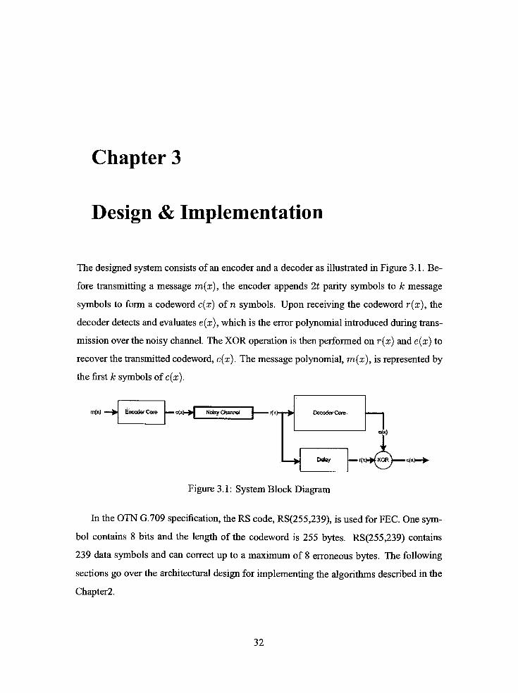
The designed system consists ofan encoder and a decoder as illustrated in Figure 3.1. Be
fore transmitting a message m(x), the encoder appends _t parity symbols to k message
symbols to form a codeword c(x) of n symbols. Upon receiving the codeword r(x), the
decoder detects and evaluates e(x), which is the error polynomial introduced during trans
mission over the noisy channel. The XOR operation is then performed on r(x) and e(x) to
recover the transmitted codeword, c(x). The message polynomial, m(x), is represented by
the first k symbols of c(x).
mfx)' EncoderCore-*>+[
Noisy Channel_\
K*)-rir> DecoderCore
hJe<x)
Deisy rw^tor^x).
Figure 3.1: System Block Diagram
In the OTN G.709 specification, the RS code, RS(255,239), is used for FEC. One sym
bol contains 8 bits and the length of the codeword is 255 bytes. RS(255,239) contains
239 data symbols and can correct up to a maximum of 8 erroneous bytes. The following
sections go over the architectural design for implementing the algorithms described in the
Chapter2.
32

3.1 Encoder
The encoder reads the message to be transmitted, calculates and appends the parity bytes
at the end of the message. A block diagram of the encoder is shown in Figure 3.2. The
i_start signal indicates the beginning ofeach message to be encoded. After the239tft
byte
has been pushed into the encoder, the i_enable signal is asserted to shift the parity bytes out
of the register.
btetefftG)
Lenable-
Lreset_r
I. start
1 dk
Encoder
ftfc.&r-fcMsytetN^iOt
Figure 3.2: Encoder Block Diagram
The codeword, c(x) is systematically encoded using (3.1).
c(x)=m(x)X16
+m{x)X16
mod g(x) (3.1)
The systematic encoder is implemented using a Linear Feedback Shift Register (LFSR) as
shown in Figure 3.3. At the end of239 clock cycles, the contents in LFSR are appended to
the 239 bytes ofdata.
CM>0*e-- e^EiH# e
data| ^ 1 I %ai___a
Codeword
Figure 3.3: EncoderArchitecture
The taps of the LFSR are defined by the coefficients of the generator polynomial g(x)
33

ofdegree 16, which is given by
15
g(x)= J] (x + a') (3.2)
i=0
Using the Galois field based on the primitive polynomial, p(z) =z8
+z4
+z3
+z2
+ 1,
the coefficients of the generator polynomial, g(x) are derived as
.10211
g(x)=
xlb
+a12Ux15
+a1U4x14
+cXxiJ
+aluyxiJ
+ awzx
+a161x10
+a76x9
+a3x8
+a91x7
+a191x6
+a147x5
+a169x4
+a182x3
+a194x2
+ a225x +a120
(3.3)
3.2 Decoder
The top-level block diagram of the decoder is shown in Figure 3.4. The i_start signal is
pulsed every 255 clock cycles to indicate the beginning of each received codeword to be
decoded and the output ofa syndrome polynomial from the syndrome calculator. The Key
Equation Solver will then take 224 clock cycles to generate the error-locator polynomial
and the error-evaluator polynomial from the syndrome polynomial. Once these two poly
nomials are formed, the Chien's algorithm [6] uses the error-locator polynomial to exhaus
tively search for the locations of the errors. After the errors have been located, the Forney's
algorithm [11] will calculate the magnitude of the errors from the error-evaluator polyno
mial. The decoder validates the codeword on the last byte of the codeword. If the received
l_sattp-:0)
l_feset_n
-Istair
o_emx_vai[7:ty
a_r*irci_'*7x*13 re
Figure 3.4: Decoder Block Diagram
34

codeword contains more than eight errors, the uncorrectable codeword is discarded. Oth
erwise, the decoder will generate the error polynomial, e(x) through o_error_val. As the
decoder outputs the error value, the odcey.ready signal is used to fetch the corresponding
received symbol from the FIFO, used to buffer the received symbols during the decoding
process. The decoder also outputs the number ofcorrected errors through o_num_errors for
statistical records.
3.2.1 Syndrome Calculator
Figure 3.5 shows the block diagram of the syndrome calculator, which is used to detect
errors in the RS decoding scheme. After the i_start signal has been pulsed, the received
i_dHtspr:GJQjtyr*k-me[-27&_
Figure 3.5: Syndrome Calculator Block Diagram
codeword is fed into the syndrome calculator through i_data at a rate ofone byte per clock.
It takes 255 clock cycles to calculate the syndrome polynomial. In the next clock cycle,
the contents of the syndrome registers are shifted into the Key Equation Solver in parallel
through s-syndrome which is a 16 x 8 bit-signal. In the same clock cycle, the syndrome
registers are preset with the first symbol of the next codeword.
The Syndrome Calculator implements the function S(x) given in (2.9). As each byte
gets in the syndrome calculator block, it is multiplied by all the roots of the generator
polynomial, g(x), in parallel as shown in Figure 3.6. Recalling g(x) from (2.4), the
roots of g{x) are given as a%, where 0 < i < 15. At the end of 255 clock cycles, af
ter the last byte has been processed, the 16 accumulator registers contain the coefficients,
r(a), r(a1), ..., r(a15) of the syndrome polynomials, S(x). These coefficients are stored
in a 128 bit register, which will be used by the Key Equation Solver. The latency of the
35

n(X>
(T> >fD}-rS0(x)
Si(x)
>ffi~-fgT-T->s,5(x)
Figure 3.6: Syndrome CalculatorArchitecture
syndrome calculator is 255 clock cycles.
3.2.2 Key Equation Solver
The Key Equation Solver block is the most complex block to implement. The block di
agram of this Key Equation Solver is shown in Figure 3.7. When the syndrome coeffi
cients are ready to be processed, the istart signal is triggered to shift the coefficients into
the Key Equation Solver. Once this signal is pulsed, the Key Equation Solver block will
Lsyndrometl2?:b|
|F-oJarflbdapi:0]
? o_<T*egaC63:0)
* ojs*p_ej:for[3;0]
*-o_key_reatJy
Figure 3.7: Key Equation Solver Block Diagram
take 224 clock cycles to generate the coefficients of error-locator polynomial, A(x), and
36

error-evaluator polynomials, fi(x). The o_exp-errorsignal represents the number of errors
estimated by the Key Equation Solver and is used by the Error-Locator block to validate
the codeword.
The Berlekamp-Massey algorithm from Figure 2.4 is translated into a state machine
shown in Figure 3.8. The state machine is started by a pulse from i_start signal. The
register A(x) is initialized to one and the expected number of errors L is set to zero. The
='0*
resetn='0'
Figure 3.8: Berlekamp-Massey State Diagram
state machine stops when r equals to _t. At this point, the register A(x) contains the
coefficients of the error-locator polynomial. The next step is to calculate the coefficients
of the error-evaluator polynomial fl(x). This is done by solving the Key Equation shown
in (2.36) for Q(x). This version ofKey Equation Solver takes 140 clock cycles, which
37

is less than 224 clock cycles for the final design, to generate A(x) and Q(x). However,
this implementation causes the overall system to run at a lower clock rate, and requires
improvement.
After analyzing the statemachine, a derivative ofthe above implementation is proposed
to speed up the design and optimize for resource utilization. The first improvement made
is to eliminate the register, T(x), which is internal to a loop of the state machine. Elimi
nating T(x) allows to combine the ShiftNorm Reg and Update Shift Reg states in Figure
3.8. To compensate for T(x), the normalizing process (B(x)<
A~xA(x)) is moved to
state ComputePoly as shown in Figure 3.9. The shift register is normalized only if the con
dition 2L < r 1 has been satisfied. When normalizing the shift register, the arithmetic,
istart-11
I start =$
mseln='0'
Figure 3.9: Proposed Berlekamp-Massey State Diagram
38

A~2A(x), is evaluated. In the Compute Poly state,A"1
represents the finite field inverse
ofAr. A typical logic implementation [14] of finite field inversion in GF(2&) usually con
sumes 16 clock cycles before generating an answer. Unfortunately, in this state machine
design, 1 6 clock cycles for one inversion is unacceptable. Before generating the locator
polynomial, A(x), there would be a most 8 inversions, which would consume 128 clock
cycles. So, the state machine would need 260 clock cycles. But, the Key Equation Solver
has only 255 clock cycles to generateA(x) before receiving the next syndrome polynomial,
S(x). Instead ofusing logics to implement the finite field inverse, a look-up table with 255
entries is used. Each entry of the look-up table represents the address of the locationwhere
the inverse of an finite field element is stored.
The Compute-Poly state is now responsible for two operations: B(x)<
_\~lA(x)and
A(x)<
A(x) _\rxB(x). These two operations are executed in parallel and consumes
a total of eighteen finite field multipliers. The proposed implementation in Figure 3.9
serializes both functions at the expense of latency. In the new design, each function shares
threemultipliers tomultiply different coefficients at different clock. As a result, the number
of Galois Field multipliers is reduced from eighteen down to six. However, the cost of
resource sharing is latency. The latency oftheKeyEquation Solver has been increased from
140 cycles to 224 cycles. An increase in latency leads to an increase in the FIFO depth,
used to buffer the received symbols during the decoding process. However, the FIFO can
be implemented in block RAMs, which are available in both Virtex4 and StratixII. These
block RAMs are not part of the programmable logics and they are wasted if they are not
used.
The speed of the initial implementation was about half the targeted clock rate. When
analyzing the timing report, most critical path contains multiplexers instantiated by the
synthesis tools. A pipeline register is added in the critical path to decrease the delay. The
state machine is then modified to compensate the additional pipeline registers. The use of
the pipeline registers helps the decoder to achieve the speed specified by the OTN G.709
[20] and the resource sharing improves the resource utilization by 15%.
39

3.2.3 Error Locator
The objective of this Error Locator block, as shown in Figure 3.10, is to generate a error
polynomial with identified locations of the errors. The error-locator takes in the error-
locator polynomial, A(x), and error-evaluator polynomial, fi(x), through iJambda and
i-omega from theKey Equation Solver, respectively. When the iJkeyjready signal is pulsed,
the error-locator starts searching for the locations of the errors by evaluating the error-
locator polynomial, A(ctX). The index i ranges from 0 to 254 and is incremented by unity
for every clock cycle. IfA(a2) = 0, the symbol at location (255 i) is erroneous and is
marked by o_sym_error signal. Such algorithm is known as the Chien's algorithm [6].
ljambdp[71:0]
l_dm&gap3-.0]
l_dk
i reset n
i>o_teirtJda_odd[7;#J
1^ ajrr*jtipN[7;0]
#*- e_syw>jerrdf
**--jiwt_ertwfafc01
* o avtd Invalid
Figure 3.10: Error Locator Block Diagram
The architecture to implement the Chien's algorithm is shown on the left ofFigure 3.11.
Once the error-location polynomial, A(x), has been generated, its coefficients A0, A1; ...,
A8 of the error-locator polynomials are preset in the registers as shown in Figure 3.11. The
output at this operation is equivalent to A(a). On the following clock cycles, the values
in the registers are multiplied by corresponding alpha to evaluate A(a1), A(a2),...A(a254).
IfA(a') = 0, then the (255i)th
symbol of the received polynomial is erroneous and,
therefore, its error magnitude needs to be evaluated. For each codeword, osym-error flags
the locations of the erroneous symbols. Each time the error-locator finds an error, it will
increment a counter to monitor the number of errors. If the number of errors obtained by
the error-locator does not match with the number of errors calculated by the key equa
tion solver, the codeword is marked as invalid and is discarded. However, if the number
40

>
ml-")
Figure 3.11: Error LocatorArchitecture
matches, the transmitted codeword can be recovered.
3.2.4 Error Evaluator
The error evaluator block, as shown in Figure 3.12, is the last step in decoding RS codes.
The error-evaluator is based on the Forney's algorithm [11], and calculates the error values
that have been introduced during the transmission. The i_sym_error signal represents the
Lfen*d&j#lfr:qj
Lome_alprisE?:01
i_sytn_ertor
i die
Error
Evaluator
' o_emor_V8![7;G]
Figure 3.12: Error Evaluator Block Diagram
41

locations of the symbols that need to be corrected. The error is calculated according to
(3.4), which is derived from (2.51) since A'{Xt) = XiAodd{Xi).
er_ = (3.4)A-odd{Xl )
Xi represents the index i in error locating process andXf1
represents the location 255 i
in the receiving codeword. The implemented architecture is based on (3.4) to evaluate the
error magnitude. The coefficients ofQ(X1) ar>d h-oddiX^1) are calculated in the Error-
Locatorblock as shown in Figure 3. 1 1 . No additional hardware was required to implement
term Aodd(Xi~1) becauseA(X['1) was calculated as the sum ofAeven(X^1) and Aodd(X,_1).
A Look-Up Table is used to store the inverse value of Xodd(al) as shown in Figure 3.13.
The look-up table is coded in VHDL such that it infers memories instead of logics since
memories are readily available in both Virtex4 and StratixII. This is done by registering the
addresses and the outputs of the look-up table. As a result, the logic can instead be used
for other functional blocks and thus improving the FPGA logic utilization.
0
Ma'HjfB}-*{___}J
Figure 3.13: Error Evaluator Architecture
3.3 Summary
The proposed RS(255,239) codec is implemented using VHDL. Theencoder has a latency
ofone clock cycle and the decoder has a latency of488 clock cycles. The FIFO should at
least be to able to store 488 bytes of incoming codewords. The overall challengein imple
menting the RS codec is the Key Equation Solver block. A state machine approach was
used to implement the Berlekamp-Massey algorithm. The originaldesign was performing
42

at only half the speed required by OTU-3. So, the state machine was redesigned with addi
tional pipeline stages to speed up the rate. The VHDL code for this block was written in a
behavioral style and portable to eitherAltera's orXilinx's FPGA devices. The other build
ing blocks were implemented in an architectural coding style where the hardware resources
are inferred. The implemented RS codec is simulated in Modelsim v6.0 and synthesized
targeting Xilinx's Virtex4 andAltera's StratixII.
43

Chapter 4
Simulation & Synthesis Results
4.1 Verification
4.1.1 MATLAB Model
To verify the functionality of the implemented RS codec, a model of the system is built
using simulink fromMATLAB as shown in Figure 4.1. The Message block is used to gen
erate a random sequence of 239 bytes, which are saved in the message file. The 239-byte
message is encoded to a 255-byte codeword, which is stored in the codeword file. Themes
sage and codeword files are used as a baseline to test implemented codec in the verification
environment. The file r_x is used to confirm that the receiving data are erroneous. Different
Initial Seed are used to generate test files with different patterns.
== 1 1
V*
ToWofcpac* TWdpaee1 T;.Wo*si*<*2
Figure 4.1: RS Model
ToWotepace3
44

The codeword is then corrupted and the erroneous codeword, r_x, is then decoded.
In this model, the RS decoder outputs the number of corrected errors and the corrected
codewords if the number of errors is eight or fewer. The decoded codeword is compared
to the generated message and the resulting frame is converted to a scalar samples output
at a higher sample rate. A horizontal line crossing the origin,(Figure 4.2 (left)), indicates
) Validation i Validation Masmm :p>P:Aiib
0 ! 2
....
Figure 4.2: Validation ofRS Codec model
that the decoded message is equal to the generated message. However ifmore than the
maximum limit number oferrors have been injected into the codeword, a step function-like
signal will be observed on the scope as shown in Figure 4.2 (right). If the number oferrors
is more than eight, the RS(255,239) codeword is not correctable and must be discarded.
4.1.2 Error Generator
The RS(255,239) decoder can correct up to eight symbol errors. An error generator, shown
in Figure 4.3, is used to produce random errors at random locations in a codeword. The
Random Location block generates a random binary error pattern consisting of Os and Is,
where a 1 indicates that an error will be injected in the corresponding location. A proba
bility of 3.5% for the Random Location block will generate codeword with an average of
9 errors out of255 symbol locations. The Random Magnitude block generates uniformly
45
Emt Pattern
Random Location
XM-ZURandom
Integer
Error
Product ToWoikspaceS
Random Magnitude
Figure 4.3: Error Generator
distributed random integers in the range of 1 and 255. Multiplying the output of the Ran
dom Location and Random Magnitude block produces a random error pattern to be added
to the codeword. A set of sixteen error patterns are generated using different Initial Seed
and stored in an error file. In the verification environment, the contents of the error file are
added to the encoded codeword to corrupt the received codeword. The received codeword
is then decoded to retrieve the injected errors.
4.1.3 Verification Environment
To test the functionality of the implemented encoder and decoder, a verification environ
ment is designed as shown in Figure 4.4. The Design Under Test (DUT) is found in the
grey box and it consists of the implemented encoder and decoder. Themessage is fed to the
Encoder through a transactorl . Transactorl acts as a controller to the encoder. Itwill send a
message of239 bytes at a rate ofone byte/clock and thereafter, it toggles the i-enable signal
of the encoder to attach the parity symbols to the message forming a 255 byte-codeword.
As the encoded bytes come out of the encoder, they are compared to the codeword file
generated fromMATLAB. Any discrepancywill assert the tb-enc_error signal to high.
The encoded codeword, c(x) is corrupted using e(x), the Error file from Error Gener
ator designed in MATLAB. The received codeword, r(x)=
c(x) + e(x) is then fed into
the RS decoder, which knows only r(x) and will calculate e(x). The transmission error,
46
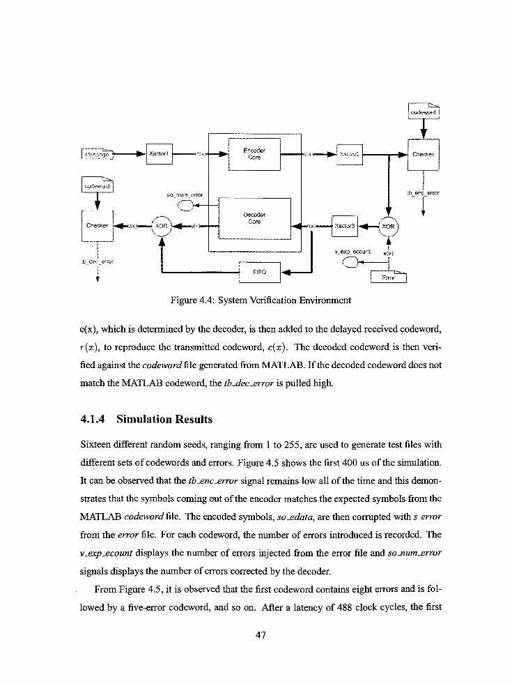
Figure 4.4: System Verification Environment
e(x), which is determined by the decoder, is then added to the delayed received codeword,
r(x), to reproduce the transmitted codeword, c(x). The decoded codeword is then veri
fied against the codeword file generated fromMATLAB. If the decoded codeword does not
match theMATLAB codeword, the tb-dec-error is pulled high.
4.1.4 Simulation Results
Sixteen different random seeds, ranging from 1 to 255, are used to generate test files with
different sets of codewords and errors. Figure 4.5 shows the first 400 us of the simulation.
It can be observed that the tb_enc_rror signal remains low all of the time and this demon
strates that the symbols coming out of the encoder matches the expected symbols from the
MATLAB codeword file. The encoded symbols, so-edata, are then corrupted with s_error
from the error file. For each codeword, the number of errors introduced is recorded. The
v_expjecount displays the number of errors injected from the error file and so_num-error
signals displays the number of errors corrected by the decoder.
From Figure 4.5, it is observed that the first codeword contains eight errors and is fol
lowed by a five-error codeword, and so on. After a latency of 488 clock cycles, the first
47

(3wave - default
Figure 4.5: Full Range Simulation
decoded symbol comes out of the decoder. The so_num-error signal from the decoder
indicates that the first decoded codeword contains eight errors, the second contains five
errors. However, this signal displays zero for the fourth, the fifth and the sixth codeword,
which have nine, thirteen and ten errors, respectively. The decoder can only correct up
to eight errors and since these codewords have more than eight errors, the decoder marks
the codeword as invalid through the so_cwrd-invalidsignal. The tbjdecjerror signal re
mains low most of the time except for the codeword with more than eight errors. This
outcomes of the signals are expected because the received codeword must be discarded.
However, regardless the codeword can be corrected or not, the testbenchwill compare the
decoded codeword to the expected codeword from MATLAB. But in this case, thetest-
bench does not know what the expected codeword is. It is comparing the decoded code
word with the expected codeword, had the codeword been correctable. This explains why
the so-cwrd-invalid signals have been asserted for the uncorrectable codewords.
Figure 4.6 shows the beginning of the encoding process. The first five bytes entering
and leaving the encoder are 3, 5, 0, 7, and 4. The s_error signal is the error to be introduced
48
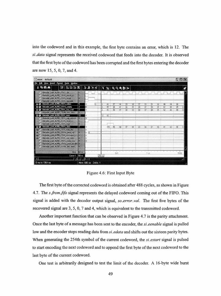
into the codeword and in this example, the first byte contains an error, which is 12. The
si-data signal represents the received codeword that feeds into the decoder. It is observed
that the first byte ofthe codeword has been corrupted and the first bytes entering the decoder
are now 15, 5, 0, 7, and 4.
53 wave- default
\___i. lJJ'Mi,l.|J,MJ.llUMiWM',fiM
* %a#*i if SiStliH hMl_\ \ fa] <^^Bx3<-
?!_eixjty_&-&j^jS~^^J3&
.'decodei_patJiJb255_239/s_sra
.
'/<X^J&%Ji-^__%>ftJ^_X$_vr*
-
h_ta^j>m,_^'&SJSiiijaj\
igf*L f&ctw_j^jt^__^_h<.Jt& \
&_*7<&fa__p&h_fo<5___*3&SQ_&!Ql_y&
$* Ak^2e*j^o2^2^;.t<=wveMHt.<t
gf.^ 'rdeoid_paih_lbi*S^33.^ei|^ris"
* /(ferJ<Kterjp^hfi52^_^35/^u_>5fla_erpjrL
> tteX^_^J_^J^f-f_%^4jttsjti* A*?irteU^jfe2^^9^?_(fec_erRL
H5, B )0 EZZEZZEI DB fi "? ra I
Figure 4.6: First Input Byte
The first byte ofthe corrected codeword is obtained after 488 cycles, as shown in Figure
4.7. The sjromfifo signal represents the delayed codeword coming out of the FIFO. This
signal is added with the decoder output signal, so_error_val. The first five bytes of the
recovered signal are 3, 5, 0, 7 and 4, which is equivalent to the transmitted codeword.
Another important function that can be observed in Figure 4.7 is the parity attachment.
Once the last byte ofamessage has been sent to the encoder, the si-eenable signal is pulled
low and the encoder stops reading data from si_edata and shifts out the sixteen parity bytes.
When generating the 254th symbol of the current codeword, the si-estart signal is pulsed
to start encoding the next codeword and to append the first byte of the next codeword to the
last byte of the current codeword.
One test is arbitrarily designed to test the limit of the decoder. A 16-byte wide burst
49

'ifeco^T_p2^GwS^253.%_)^p_,ecw#
/decoder Dath Ib255 239/s from hfo i 5
H-^ Afeccder_p.*hJb255239/so_crroi_val ; 0
nnjssn
4~Ho737TTBgTirTnrTri3nsiE7T35i~T46??BItr:>"iCTn3H3rmTO
LiiSII^ESEX^XJiDSSSZIiQIIlZSLLIOII'BSDOSjIBIo:
i5i~,rTr7nTinnTn~
pttb~
g | yt mxirrrrr
Diar
rUi*i*tJ,iSUBS!t: SJ&njsumj-irar
)tfe<feiJK^lb255239/so_Gwr^_ffl-/a6S./4tcoder_lj38u1^S_^2J^.d*c*rta
")r.rrnrir^Tnnr)nrin5 vm is it myi2 1?i<~
3 is io girts hi 17 n v i? Ti mn.2 17 u
JL
Figure 4.7: First Decoded Byte
error is injected in the stream ofdata. The burst error is spread over two codewords causing
the last consecutive eight bytes ofone codeword and the first consecutive eight bytes of the
following codeword to be erroneous. The burst errors model the worst case scenario of the
error pattern, which could potentially occur in the OpticalNetworks. After 488 clocks, the
correct symbols are generated and compared to the MATLAB generated codeword files.
The tb-dec-errorremains low throughout the decoding of these two codewords. The simu
lation results show that all the sixteen bytes of the two codewords have been recovered by
the decoder.
4.1.5 Post-Synthesis Simulation
The synthesized models are generated for Altera's QuartusII and Xilinx's ISE for sim
ulation. In the QuartusII tool, under Settings EDA Tool Settings > Simulation, the
ModelSim-Altera (VHDL) option is selected as the Tool name. The two boxes Maintain
hierarchy and Generate netlistforfunctional simulation only are checked and the design
50

;3wwo~(ipfaM!!
nia::Tiriv
->ri^c__ttJ:*-JhX_}JV_!'_e^iit
sjri :* a Si^*ux3<-|
Figure 4.8: Burst Error
is synthesized. The netlist file (RS255_239.vho) is generated in the ../simulation/modelsim
Figure 4.9: Altera Post-Synthesis Simulation
folder, which is created by the EDA Netlist Writer. The generated entity is instantiated in
the testbench and simulated in ModelSim_altera 6.0c. The simulated results are shown in
Figure 4.9.
In the ISE tool, thePost-SynthesisSimulationModel is generatedwith the default option
to targetModelSimXE (VHDL). The netlist file (decoder_path_synthesis.vhd) is generated
in the local folder. The generated entity is instantiated in the testbench and simulated in
ModelSimXE II.
51

Figure 4.10: Xilinx Post-Synthesis Simulation
From the simulation windows, shown in Figure 4.9 and Figure 4.10, it is observed that
the testbench test signals behave similarly to the signals in Figure 4.5. The simulation re
sults demonstrate that the designs are functionally equivalent after being being synthesized
using different synthesis tools.
4.2 Synthesis Results
The RS(255,239) codec is instantiated in a top level entity and is wrapped with registers as
shown in Figure 4.1 1. The function of the registers is to prevent the core's primary regis
ters to be potentiallymapped into IOBs (I/O Block registers) whichwould result in a lower
logic count. The design is synthesized usingAltera's QuartusII v5.0 andXilinx's ISE v7. 1 .
The QuartusII tool offers three different optimization techniques: Speed, Balance orArea.
The ISE tool, on the other hand, does optimization in two steps. The design is synthesized
for either area or speed. The synthesized design is then mapped to achieve either the least
amount of resource utilization or the highest speed. The trade-off between resource uti
lization and area is not obvious when implementing OTU-3 FEC [20] in FPGAs. Since the
OTU-3 has a specified serial data rate of40Gbps, a 32 byte data bus is used at a speed of
169MHz. To satisfy this requirement, not only the RS decoder needs to run at a speed of
169 MHz, but it needs to be small enough to fit a total of 32 decoders in one FPGA. The
52
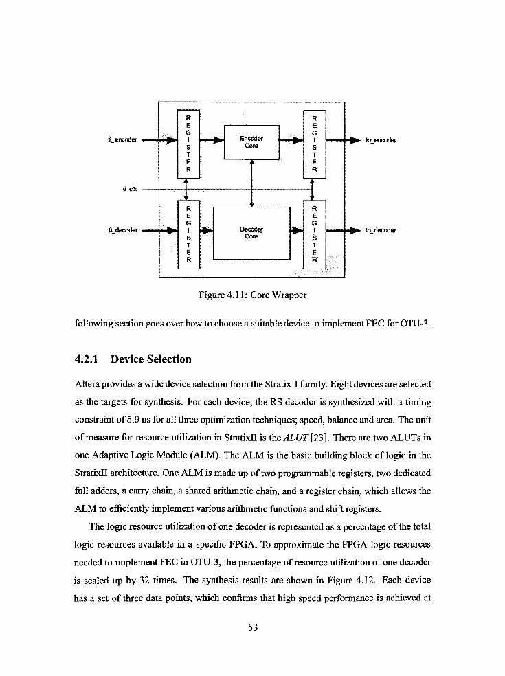
i_encoder
g elk
Ldecoder
to^encoder
to. decoder
Figure 4.1 1 : Core Wrapper
following section goes over how to choose a suitable device to implement FEC forOTU-3.
4.2.1 Device Selection
Altera provides a wide device selection from the StratixII family. Eight devices are selected
as the targets for synthesis. For each device, the RS decoder is synthesized with a timing
constraint of5.9 ns for all three optimization techniques; speed, balance and area. The unit
ofmeasure for resource utilization in StratixII is theALUT [23]. There are two ALUTs in
one Adaptive Logic Module (ALM). The ALM is the basic building block of logic in the
StratixII architecture. One ALM ismade up of two programmable registers, two dedicated
full adders, a carry chain, a shared arithmetic chain, and a register chain, which allows the
ALM to efficiently implement various arithmetic functions and shift registers.
The logic resource utilization ofone decoder is represented as a percentage of the total
logic resources available in a specific FPGA. To approximate the FPGA logic resources
needed to implement FEC in OTU-3, the percentage of resource utilization ofone decoder
is scaled up by 32 times. The synthesis results are shown in Figure 4.12. Each device
has a set of three data points, which confirms that high speed performance is achieved at
53

250
200
N
I .
S tso^_m*
c
_
I
50
' L-X'. I
r:* F*
je. i
f Ir-
vX
^-2S15C5F484
- 2S15C3F484
-^ 2S30C5F484
-HH-2S30C3F484
^* 2S60C5F484
-*- 2S60C3F484
I 2S90C5F1020
2S90C3F1020
169 MHz
0 -SO 100 150 200 250 300 350 400 450 500
% Resource needed for OTU-3
Figure 4.12: Synthesis ofRS decoder on StratixII
the expense ofhardware resources. The plot is divided into four regions; a horizontal line
to represent a threshold frequency of 169 MHz and a vertical line at 100% representing
that the entire decoderwill use up the total available logic resources in one FPGA. Among
the selected StratixII devices, the graph shows that only the 2590(73^1020 device can be
used to fit 32 RS decoders running at a frequency of 169MHz. The optimization technique
"optimizing forarea"
is opted because not only the synthesized design utilizes the least
amount of resources, but also meets the required frequency.
Similarmethodologies are adopted to select a Virtex4 device from Xilinx. Among the
three available platforms, six devices are selected from the Virtex4-FX platform due to its
Rocket I/O [24] feature. The synthesis flow in ISE is different from QuartusII's. On each
of selected Virtex4 devices, the design is synthesized using four optimization techniques,
which are "Synthesized for area and mapped for area", "Synthesized for area and mapped
for speed", "Synthesized for speed and mapped forspeed,"
and "Synthesized for speed and
mapped forarea."
The Virtex4's basic building block is called the Configurable Logic Block
(CLB) [25]. One CLB consists of two pair ofSlices (SliceL and SliceM), and one Slice
54

100 150
%Resource needed for OTU-3
Figure 4. 13: Synthesis ofRS decoder on Virtex4
250
is the unit ofmeasure for the logic resource utilization. Each slice contains two function
generators, two storage elements, some arithmetic logic gates and fast carry look-ahead
chain. SliceL is used as logics only, and SliceM can be configured as logic, distributed
RAM or shift register.
The synthesis results are displayed in Figure 4.13, and reveal that among the selected
Virtex4 devices, only the xc4vfxl40 12/1517 device can potentially be used to imple
ment RS decoder to support FEC in OTU-3. Among the four selected optimization tech
niques in ISE, "Synthesized for area andmapped forarea"
optimization technique is chosen
to obtain a designwith the least amount ofslices while respecting the specified timing con
straint. When comparing Figure 4. 12 to Figure 4. 1 3, it is observed that the StratixII devices
exhibits the same behavior irrespective theymeet timing or not. However, the Virtex4 de
vices behave differently. This is due to the difference in the constraint and timing analysis
philosophies ofQuartusII and ISE. By default, the QuartusII tool analyzes and optimizes
all possible paths, disregard ofwhether they are constrained or not. However, the ISE tool
focuses only on constrained paths and does not optimize or report unconstrained paths. To
55

test for the maximum performance of the proposed decoder on Virtex4, the threshold of
169MHz needs to be raised until the design does not meet the timing requirement.
4.2.2 Resource utilization by individual decoding block
Once the optimization technique for each synthesis tools has been selected, the percentage
logic resource utilization of individual functional block relative to one RS decoder is an
alyzed on both 2590C3F1020 and xc4vfxl40 - 12/1517. The pie charts in Figure 4.14
represent the percentage utilization of each block in one RS decoder in both StratixII and
Virtex4 device. It can be observed that the percentage of resources allocated to the Key
Equation in Virtex4 is more than that in StratixII. The reason behind this difference is the
use ofmemory to implement the look-up table. Xilinx's ISE tool translates the Key Equa
tion's look-up table into Read-Only Memory (ROM), which is implemented using logic
blocks. However, the StratixII architecture allows Altera's QuartusII tool to pushes the
look-up table into the memory, resulting in a less logic resource utilization. Anotherobser-
Chien
14%
Forney Syndrome
4%
Chien Fomey Syndrome
3% SOi
StratixII
Key Equation
68%
Virtex4
Key Equation
78%
Figure 4.14: Relative Functional Block Utilization
vation is the difference in the percent logic utilization between the Chien and the Syndrome
blocks. The distribution in Virtex4 is expected and reflects the VHDL code in terms of
the number of logic blocks. However, in StratixII, both blocks share the same percentage
of logic utilization. This is the result of "registerpacking,"
which is a feature in StratixII
that allows the device to utilize the unused register or combinational logic ofone ALM for
unrelated functions.
56

4.2.3 Benchmark
The optimized version of the proposed RS decoder is then compared to Altera's decoder
on six StratixII devices. Using theMegaWizardPlug-InManager, Altera's Reed-Solomon
decoder v4.0 [21] is generated and instantiated in a top-lever wrapper. The optimization
technique is set for area with a timing constraint of 5.9ns. Figure 4.15 shows the compari-
Performance
C<T
>c^ c* DeviceV V
'v'
Resource Utilization
,&
3>V
<& <&
r$ r r*
# J?
# Device
Figure 4.15: Altera's vs Proposed Decoder
son between Altera's decoder and the proposed decoder. The graph on the left presents the
high frequency capability of the proposed decoder in contrast with Altera's RS decoder.
The targeted frequency was achieved only on the fast StratixII device while the resource
utilization was independent on the device selection. The graph on the right represents the
logic resource utilization of both decoders. It is observed that the proposed implementa
tion utilizes less logic resources than Altera's core, independent of the speed grade. The
same trend follows for memory utilization too. Altera's decoder utilizes 14336 memory
bits while the proposed decoder utilizes 4096 memory bits.
The portable RS decoder is then compared to Xilinx's RS decoder. Using theCore-
Gen & Architecture Wizard tool, the Xilinx's RS(255,239) decoder [22] is generated and
instantiated in a top-level wrapper. Before synthesizing the designs, the optimization goal
for synthesis and the optimization strategy for mapping were set for area with a timing
constraint of 5.9ns. The collected data are presented in Figure 4.16. The required speed
57

Performance
# -#X^ ^ if ^
*r *T ,/ # # .
Figure 4.16: Xilinx's vs Proposed Decoder
to support FEC in OTU-3 [20] is met by the proposed decoder targeting the fast device as
shown on the left side graph ofFigure 4.16. The plot on the right represents the logic re
source utilization ofboth decoders on selected Virtex4 devices. The synthesis results show
that the Virtex4 architecture favors Xilinx's RS decoder in terms of logic resource utiliza
tion. Xilinx's decoder is utilizing about half the logic resources utilized by the proposed
decoder. However, in terms of the memory resources, Xilinx's decoder is using 2 RAM
blockswhile the proposed implementation is utilizing only 1 RAM block out of232 blocks
in fx60, 376 blocks in fxlOO and 552 blocks in fxl40. One major difference between Xil
inx's decoder and the proposed decoder is the implementation oftheKeyEquation [4]. Xil
inx implements the Euclidean algorithm [32] to solve theKeyEquationwhile the proposed
decoder uses the Berlekamp-Massey algorithm [26]. The results are"unexpected"
because
the research [31] in ASIC suggested that the BM algorithm consumes less resources than
the Euclidean algorithm. It seems that the argument is not valid on FPGA. Depending on
the device architecture, the Euclidean algorithm can utilize less logic resources than the
Berlekamp algorithm as shown in the Resource Utilization graph ofFigure 4.16.
The results show that the proposed decoder can support FEC in OTU-3 if it is imple
mented in a fast speed grade and high density FPGA. The smallest StratixII device that
could be used to implement FEC is the 2590C3 device. As for Virtex4, the only device
from the FX family that could used is the xc4vfx!40 10 device. These two FPGA devices
58

were selected among the others after synthesizing the design on each device with different
optimization technique. It was found that these two devices would fit the 32 RS decoders
needed to support FEC at a rate of 169 MHz. Moreover, it was observed that on Virtex4,
the Euclidean algorithm,which is known to consume more resources thanBerlekamp algo
rithm on ASICs, actually utilizes less logic resources than the Berlekamp algorithm. This
"unexpected"
results lead to the future work, which involves designing a Euclidean-based
RS decoder to confirm the performance ofEuclidean 's algorithm on FPGA devices.
59

Chapter 5
Conclusion & FutureWork
More than 80% of the world's long-distance and data traffic is carried over fiber-optics,
ranging from global networks to desktop computers. To increase the reliability ofdata, the
concept ofForward Error Correction (FEC) is adapted. FEC is a technique used to correct
transmission errors at the receiving side. FEC is highly used in OTN G.709 protocol [20].
The protocol defines three standard interfaces, OTU-1, OTU-2 and OTU-3, providing per
formance and facilitating evolution to higher backbone bandwidths. The OTU-3 standard
interface, which has the highest data transfer rate of43 Gbps, is still under development.
To achieve a rate of43 Gbps, a databus of32 bytes clocking at 169MHz is used.
Since FPGA has become very popular in industrial product development, we proposed
an FPGA implementation of the RS(255,239) codec miming at a minimum frequency of
169MHz. As expected, the Key Equation Solver block was the bottle-neck of the RS de
coder in terms ofboth speed and logic resource utilization. Pipelining the critical path and
serializing logics through resource sharing helped in improving the timing and resource
utilization. The optimization did result in an average speed up of 100% and an average re
duction of 13% in logic resource utilization. The synthesis results showed that the proposed
decoder could operate at a minimum frequency of 169MHZwhen targeting the high-speed
grade devices. Moreover, an FPGA with a high logic count shall be selected to implement
FEC in OTU-3.
Research work in the literature has suggested that the Berlekamp-Massey algorithm
consumes less resources than the Euclidean algorithm on ASICs. However, this argument
60

may not be valid on FPGAs. When developing in FPGAs, the performance does not only
depend on the design of the system, but also on the architecture of the targeted device. Xil
inx's RS decoder, which implements the Euclidean algorithm to solve the Key Equation,
utilizes almost half the logic resources utilized by the proposed decoder, which implements
the Berlekamp-Massey's algorithm. The Virtex4 architecture seems to favor the Euclidean
algorithm. However, it is not clear if the low logic count and block memory utilization of
the Euclidean algorithm is consistent on all FPGAs or valid only on Virtex4. The future
work will involve designing a RS(255,239) decoder using the Euclidean algorithm to solve
theKeyEquation to generate the error-locator and error-evaluatorpolynomial. The research
must be geared toward analyzing the algorithm to see which part could be implemented us
ingmemory blocks instead of logic blocks. The Euclidean-based RS decodermust be able
to run at a minimum frequency of 169MHz to support FEC in OTU-3. The performance
and resource utilization of the Euclidean-based RS decoderwill then be measured on both
StratixII and Virtex4 devices. The data will confirm how the algorithm used to implement
the Key Equation Solver depends on the FPGA architecture.
61

Bibliography
[1] E.R Berlekamp. Algebraic Coding Theory. New York: McGraw-Hill, 1968.
[2] C. Berrou, A. Glavieux, and P. Thitimajshima. Near Shannon Limit Error-correcting
Coding and decoding: Turbo-codes. IEEE International Conference on Communica
tions, 2:1064-1070,May 1993.
[3] S.R. Blackburn and W.G. Chambers. Some remarks on an algorithm of fitzpatrick.
IEEE Transactions on Information Theory, 42(4):1269-1271, July 1996.
[4] Richard E. Blahut. Algebraic CodesforData Transmission. Cambridge Publishers,
2003.
[5] M.H. Cheng. Generalised berlekamp-massey algorithm. IEE Proceedings - Commu
nications, 149(4):207-210, August 2002.
[6] R. T. Chien. Cyclic decoding procedures for bose-chaudhuri-hocquenghem codes.
IEEE Transactions on Information Theory, IT:357-363, October 1964.
[7] Anh Dinh and Daniel Teng. Design ofa high-speed rs(255,239) decoder using 0.1 8m
cmos. In Proceedings ofCanadian Conference on Electrical and Computer Engi
neering,May 2004.
[8] A. Drukarev and Jr D. Costello. A Comparison ofBlock and Convolutional Codes in
ARQ ErrorControle Schemes. IEEE Transactions on Communications, 30(11):2449-
2455, November 1988.
[9] P. Fitzpatrick. On the key equation. IEEE Transactions on Information Theory,
41(5): 1290-1302, Septempter 1995.
[10] A. Flocke, H. Blume, and T. G. Noll. Implementation andmodeling ofparametrizable
high-speed reed solomon decoders on FPGAs. Advances in Radio Science, 3:271-
276,March 2005.
62

[11] G. D. Forney. On decoding bch codes. IEEE Transactions on Information Theory,
IT:549-557, October 1965.
[12] Charles Constantine Gumas. Turbo codes rev up error-correcting performance. Per
sonal Engineering and Instrumentation News, pages 61-66, January 1998.
[13] A. Haase, C. Kretzschmar, R. Siegmund, D. Muller, J. Schneider, and M. Langer.
Design ofreed solomon decoder using partial dynamic reconfiguration ofxilinx virtex
fpgas - a case study. In Proceedings ofthe IEEEInternational Conference onDesign,
Automation and Test,March 2002.
[14] Eui-Seok Kim and Yong-Jin Jeong. A New Finite Field Divi
sion (FFD) Algorithm and its Hardware Architecture. accessible via
http://rta.gwu.ac.kr/publications/euiseok/2004J0_Finite%20Field%20Division.pdf,
October 2004.
[15] Hanho Lee. Modified euclidean algorithm block for high-speed reed-solomon de
coder. Electronics Letters, 37(14):903-904,May 2001.
[16] Hanho Lee. A vlsi design of a high-speed reed-solomon decoder. In Proceedings of
the 14thAnnual IEEE InternationalASIC/SOC Conference, 2001.
[ 1 7] Hanho Lee. An area-efficient euclidean algorithm block for reed-solomon decoder. In
Proceedings ofthe IEEE Computer SocietyAnnual Symposium on VLSI, May 2003 .
[18] Hanho Lee. A high-speed low-complexity reed-solomon decoder for optical commu
nications. IEEE Transactions on Circuits andSystems II, 52:461-465, August 2005.
[19] Hanho Lee and A. Azam. Pipelined recursive modified euclidean algorithm block
for low-complexity, high-speed reed-solomon decoder. IEE Electronics Letters,
39:1371-1372, September 2003.
[20] Manual. Interfaces for the Optical Transport Network (OTN), March 2003.
[21] Manual. Reed-Solomon Compiler User Guide, January 2003.
[22] Manual. Reed-Solomon Decoder v5.1, April 2005.
[23] Manual. Stratix Device Handbook,May 2005.
[24] Manual. Virtex-4 User Guide, September 2005.
63

[25] Manual. Virtex-4 Family Overview, February 2006.
[26] J.L Massey. Shift register synthesis and bch decoding. IEEE Transactions on Infor
mation Theory, Vol. IT-18(1):196-198, January 1969.
[27] White Paper. A G.709 Optical Transport Network Tutorial, October 2003.
[28] Arun Raghupathy and K. J. R. Liu. Algorithm-based low-power/high-speed reed-
solomon decoder design. IEEE Transactions on Circuits andSystemsII: Analog and
Digital SignalProcessing, 47(1 1):1254-1269, November 2000.
[29] Irving S. Reed and Gustave Solomon. Polynomials codes over certain finite fields.
SIAM, Vol 8(2):300-304, 1960.
[30] Frederic Rivoallon. Achieving Breakthrough Performance in Virtex-4 FPGAs, May
2005.
[31] Dilip V Sarwate and Naresh R. Shanbhag. High-speed architectures for reed-
solomon decoders. IEEE Transactions on Very Large Scale Integration (VLSI) sys
tems, 9(5):641-655, October 2001.
[32] Y. Sugiyama, Y. Kasahara, S. Hirasawa, and T Namekawa. Amethod for solving key
equation for goppa codes. Information and Control, Vol 27:87-99, 1975.
[33] International Telecommunication Union. ITU-TG. 709, February 2001 .
[34] Andrew J. Viterbi. Error bounds for convolutional codes and an asymptoticallyop-
timim decoding algorithm. IEEE Transactions on Information Theory, 13(1 1):260
269, April 1967.
[35] Stephen B. Wicker. TheDecoding ofBCH andReed-Solomon Codes. Prentice Hall,
1995.
[36] Stephen B. Wicker and Vijay K. Bhargava. Reed-solomon codes and their applica
tions. In Proceedings ofIEEE 18thAnnual Workshop on Computer Communications,
1994.
64