new delivering 40gbps optical communication systems
DESCRIPTION
Delivering 40Gbps Optical Communication SystemsTRANSCRIPT

Delivering 40GbpsDelivering 40Gbps OpticalOpticalCommunication SystemsCommunication Systems
Eldon Staggs, Steve Rousselle, and Daniel WuEldon Staggs, Steve Rousselle, and Daniel Wu

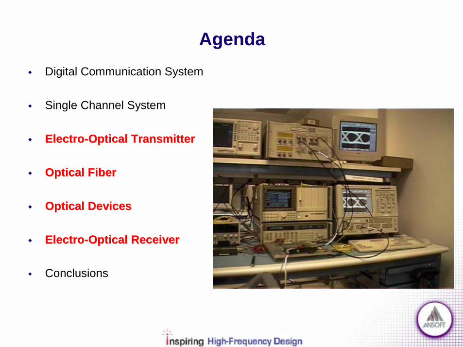
Agenda! Digital Communication System
! Fiber-Optic System Standards
! Single Channel System
!! ElectroElectro--Optical TransmitterOptical Transmitter
!! Optical FiberOptical Fiber
!! Optical DevicesOptical Devices
!! ElectroElectro--Optical ReceiverOptical Receiver
! Conclusions
Agenda! Digital Communication System
! Single Channel System
!! ElectroElectro--Optical TransmitterOptical Transmitter
!! Optical FiberOptical Fiber
!! Optical DevicesOptical Devices
!! ElectroElectro--Optical ReceiverOptical Receiver
! Conclusions
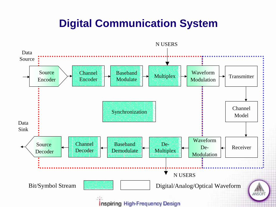
Digital Communication System
Bit/Symbol Stream Digital/Analog/Optical Waveform
Channel Encoder
Baseband Modulate Multiplex Transmitter
ChannelModel
ReceiverDe-Multiplex
Baseband Demodulate
Channel Decoder
N USERS
N USERS
Data Source
Data Sink
Synchronization
WaveformModulation
WaveformDe-
Modulation
Source Decoder
SourceEncoder

Digital Communication System
! Optical Communications System! Information encoded/decoded for pertinent protocol & modulation scheme! Multiple sets of data are combined/separated through TDM & WDM! Fiber Optic components provide the channel linking Transmitter to Receiver
N Users/ Wavelength
Video/ Audio/ Data
Enco
de
TDM
MU
XD
EMU
X
λm
Decode
λ1Optical Optical ChannelChannel
λm
λ1
TDM
Video/ Audio/ Data
Fiber Optic System Standards SectionFiber Optic System Standards Section
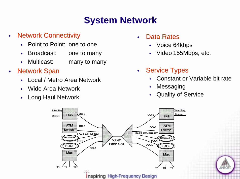
System Network!! Network ConnectivityNetwork Connectivity
! Point to Point: one to one! Broadcast: one to many! Multicast: many to many
!! Network SpanNetwork Span! Local / Metro Area Network! Wide Area Network! Long Haul Network
!! Data RatesData Rates! Voice 64kbps! Video 155Mbps, etc.
!! Service TypesService Types! Constant or Variable bit rate! Messaging! Quality of Service

OSI Reference Network Model
!! Open System Interconnection (OSI) Reference ModelOpen System Interconnection (OSI) Reference Model! Most systems use some form of OSI! L1: Physical & electrical elements! L2: Media access strategy! L3: Network maintenance (IP)! L4: Transport management (TCP)! L5: Link maintenance! L6: Format presentation! L7: Application link
!! Layers ModeledLayers Modeled! Physical (L1)! Medium Access (L2)

Fiber Optic System Standards
!! SonetSonet/SDH/SDH! Multiple data rates allowed! OC-x (x*51.84Mbps)! OC-768 = 40Gbps
!! FDDIFDDI! 100Mbps, Dual Token Ring
!! EthernetEthernet (IEEE802.3)! 10Mbps! High Speed (100Mbps)! Gigabit Ethernet
!! ATMATM! 53Byte packets! Connection oriented
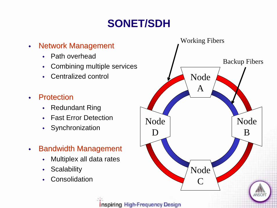
SONET/SDH
!! Network ManagementNetwork Management! Path overhead! Combining multiple services! Centralized control
!! ProtectionProtection! Redundant Ring! Fast Error Detection! Synchronization
!! Bandwidth ManagementBandwidth Management! Multiplex all data rates! Scalability! Consolidation
NodeA
NodeC
NodeD
NodeB
Working Fibers
Backup Fibers
SONET/SDH
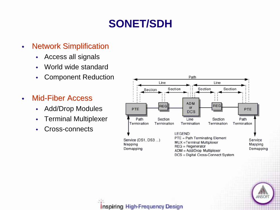
!! Network SimplificationNetwork Simplification! Access all signals! World wide standard! Component Reduction
!! MidMid--Fiber AccessFiber Access! Add/Drop Modules! Terminal Multiplexer! Cross-connects
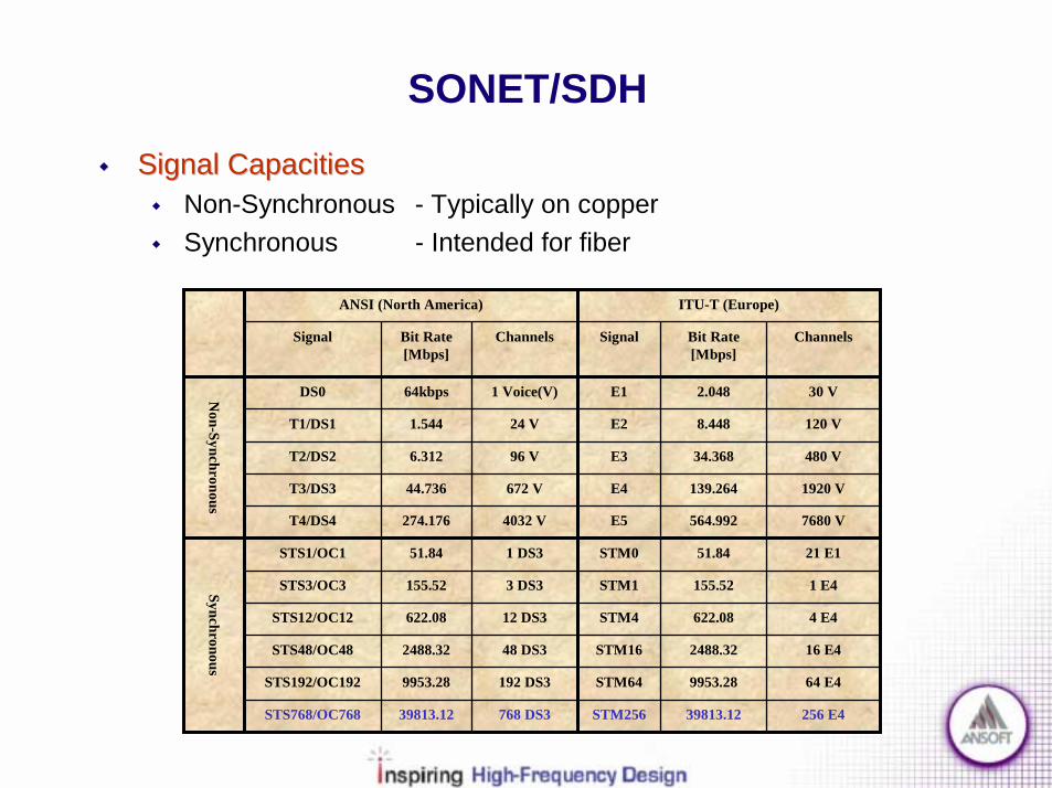
SONET/SDH!! Signal CapacitiesSignal Capacities
! Non-Synchronous - Typically on copper! Synchronous - Intended for fiber
16 E42488.32STM1648 DS32488.32STS48/OC48
4 E4622.08STM412 DS3622.08STS12/OC12
1 E4155.52STM13 DS3155.52STS3/OC3
256 E439813.12STM256768 DS339813.12STS768/OC768
64 E49953.28STM64192 DS39953.28STS192/OC192
21 E151.84STM01 DS351.84STS1/OC1
Synchronous
7680 V564.992E54032 V274.176T4/DS4
1920 V139.264E4672 V44.736T3/DS3
480 V34.368E396 V6.312T2/DS2
120 V8.448E224 V1.544T1/DS1
30 V2.048E11 Voice(V)64kbpsDS0Non-Synchronous
ChannelsBit Rate [Mbps]
SignalChannelsBit Rate [Mbps]
Signal
ITU-T (Europe)ANSI (North America)

SONET
!! SONET STSSONET STS--1 Frame Structure1 Frame Structure! Transport Overhead! Path Overhead! Bit Rate vs Data Rate
⋅==
⋅⋅⋅==
BitsRowBitsDataRateBitMbpsRateData
bytebits
rowbytes
framerowsframesMbpsRateBit
_90_84_384.48_
8909sec
800084.51_
90 Columns (Bytes)
STS-1 SynchronousPayload Envelope
Tran
spor
tO
verh
ead
Path
Ove
rhea
d
9 R
ows (
Byt
es)
LineOverhead
SectionOverhead
86 Columns (Bytes)
125u
sec

SONET!! STSSTS--1 Synchronous Payload Envelope1 Synchronous Payload Envelope
! Virtual Tributaries / Groups! Pointers! Column Interleaving! STS-N Extensions
9 R
ows
Path
Ove
rhea
d
Stuf
fed
Bits
Stuf
fed
Bits
Virt
ual T
ribut
ary
Gro
up
84 Payload, 2 Stuffed, & 1 POH Column
12 Columns
Virt
ual T
ribut
ary
Virt
ual T
ribut
ary
Virt
ual T
ribut
ary
Virt
ual T
ribut
ary
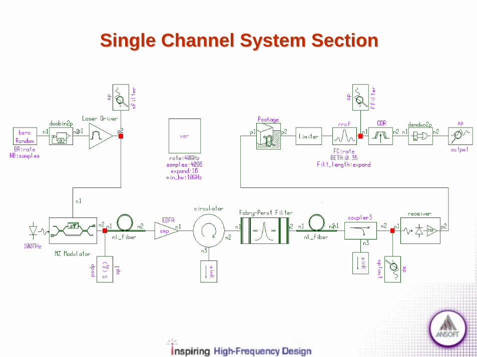
Single Channel System SectionSingle Channel System Section

Single Channel System
!! Single ChannelSingle Channel! Prove ideal set up first! Establish system limitations! TDM & WDM extensions
!! SONET/SDHSONET/SDH! OC-768 (40Gbps)! Defines lower level OSI layers
!! Physical MediumPhysical Medium! 1550nm wavelength! Single Mode Fiber

Multiple Channel System
!! Wavelength Division MultiplexingWavelength Division Multiplexing! Multiple protocols can be combined on a single fiber! Throughput expansion with colors! Optical Traffic Control
! Add/Drop, Mux/Demux, etc.! Complex non-linear effects
! FWM, DFG, SRS, SBS, XGM and XPM
!! Time Division MultiplexingTime Division Multiplexing! Traditional Electrical systems! Combine users into time slots! Timing interference effects
! Aperture jitter, Intersymbol Interference, etc.

ElectroElectro--Optical Transmitter SectionOptical Transmitter Section

Electro-Optical Transmitter
!! Source EncodingSource Encoding
!! Channel EncodingChannel Encoding
!! Baseband ModulationBaseband Modulation
!! Baseband Filtering/Pulse ShapingBaseband Filtering/Pulse Shaping
!! Light Source GenerationLight Source Generation
!! Optical Carrier ModulationOptical Carrier Modulation
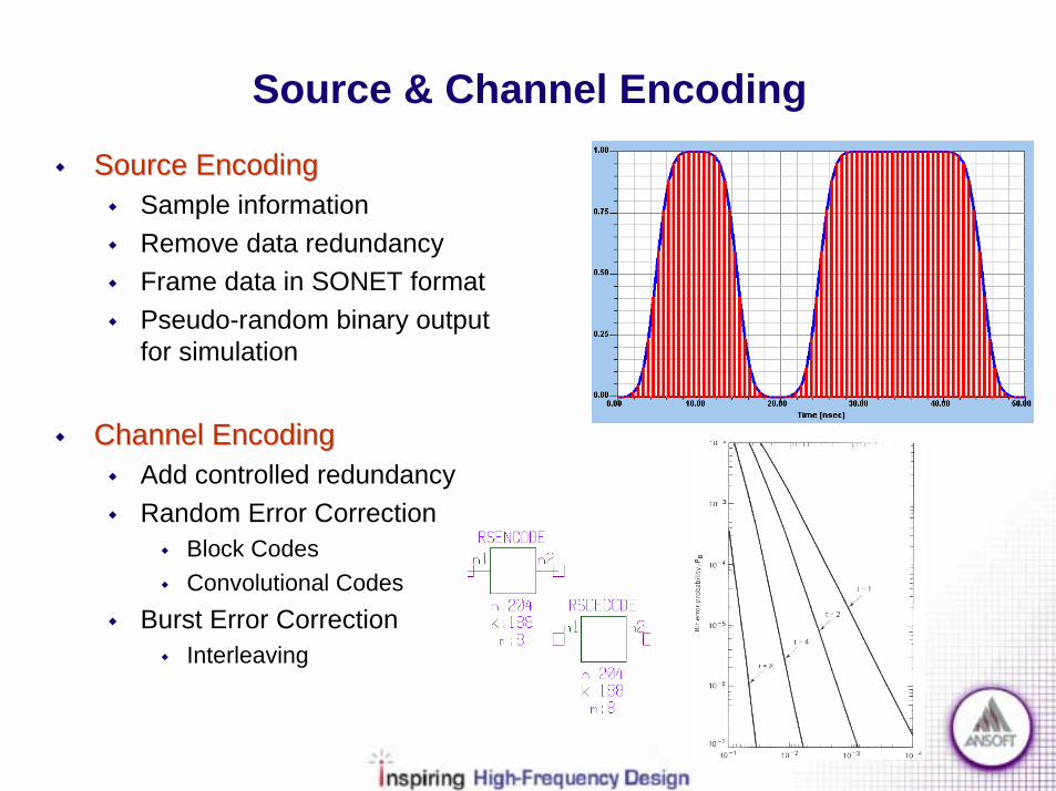
Source & Channel Encoding!! Source EncodingSource Encoding
! Sample information! Remove data redundancy! Frame data in SONET format! Pseudo-random binary output
for simulation
!! Channel EncodingChannel Encoding! Add controlled redundancy! Random Error Correction
! Block Codes! Convolutional Codes
! Burst Error Correction! Interleaving
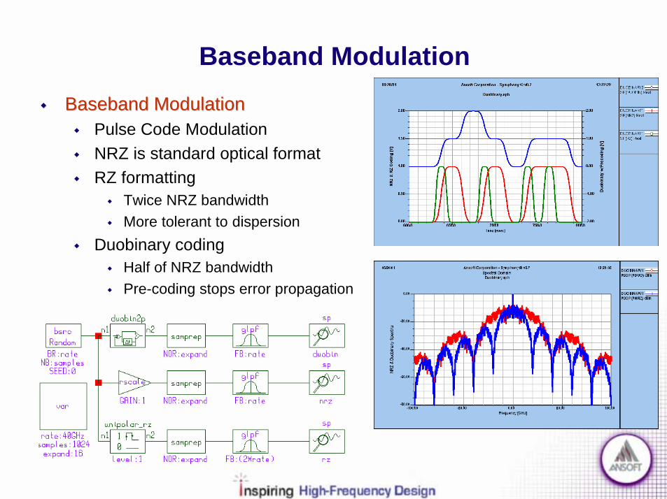
Baseband Modulation!! Baseband ModulationBaseband Modulation
! Pulse Code Modulation! NRZ is standard optical format! RZ formatting
! Twice NRZ bandwidth! More tolerant to dispersion
! Duobinary coding! Half of NRZ bandwidth! Pre-coding stops error propagation

Baseband Modulation!! Duobinary with PreDuobinary with Pre--codingcoding
! XOR input w/past output! Output= XOR + past output! SNR performance down 4.77dB! Half of NRZ bandwidth! Decoding is simply mod2(signal)
NRZDuobinary
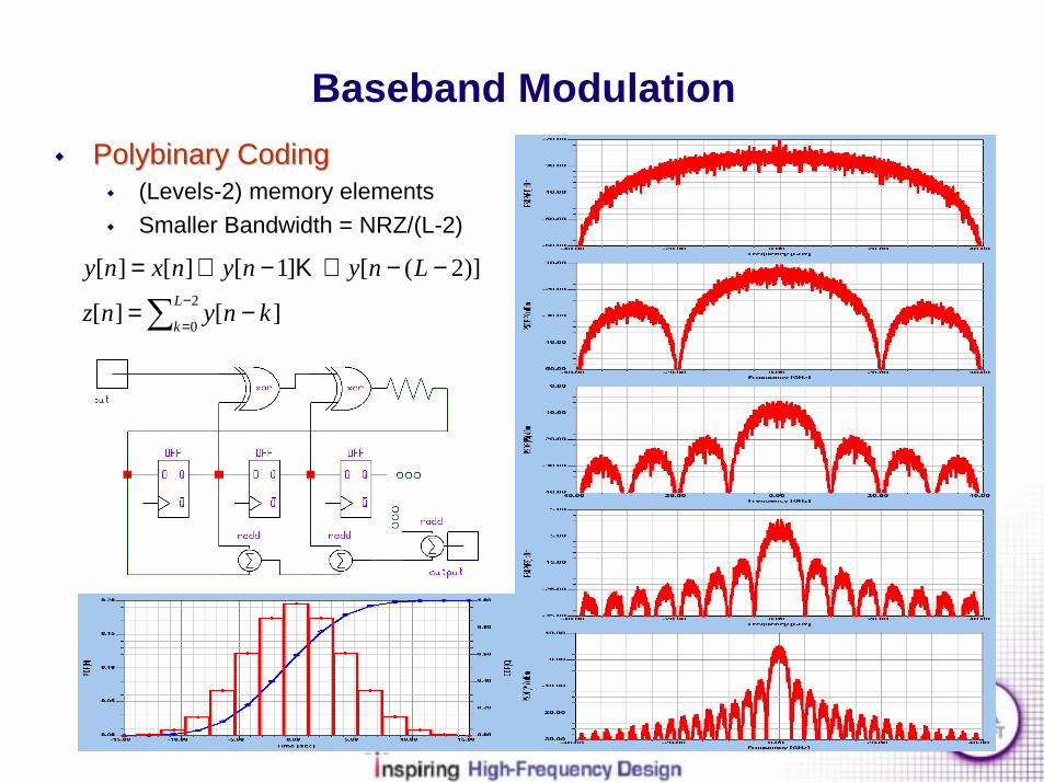
Baseband Modulation!! Polybinary CodingPolybinary Coding
! (Levels-2) memory elements! Smaller Bandwidth = NRZ/(L-2)
∑ −
=−=
−−⊕−⊕=2
0][][
)]2([]1[][][L
kknynz
Lnynynxny Κ

Baseband Filtering
!! Baseband FilteringBaseband Filtering! Spectral Containment! Pulse Shaping! RRCF, Gaussian, Sech, etc.
!! Modulator PreModulator Pre--conditioningconditioning! Scale signal prior to optical modulator

Optical Source
!! LEDLED! Low Power, Cost, Speed! Incoherent light! Line width (50-100nm)
!! LaserLaser! Coherent! Narrow spectral width (<8nm)! Temp. & Power control needed! Noise & Chirp
n-InP n-InGaAsP p-InP
1.35eV1.35eV
0.8eV
phph
hchEλ
υ ==

LASER Types
!! FabryFabry--Perot (FP)Perot (FP)! LED with mirrors! Index & Gain Guided! Multiple Modes! Spectral width (5-8nm)
!! Distributed Feedback (DFB)Distributed Feedback (DFB)! Internal Bragg Grating! Low noise & chirp! Narrow line width (50kHz)! Sensitive to Reflections & Temp.! High cost
Active Region
Active Region
⋅=Λ
nm ph
Bragg2λ
⋅=
nmL ph
cavity2λ
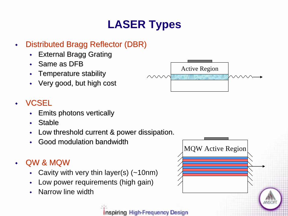
LASER Types!! Distributed Bragg Reflector (DBR)Distributed Bragg Reflector (DBR)
!! External Bragg GratingExternal Bragg Grating!! Same as DFBSame as DFB!! Temperature stabilityTemperature stability!! Very good, but high costVery good, but high cost
!! VCSELVCSEL!! Emits photons verticallyEmits photons vertically!! StableStable!! Low threshold current & power dissipation.Low threshold current & power dissipation.!! Good modulation bandwidthGood modulation bandwidth
!! QW & MQWQW & MQW! Cavity with very thin layer(s) (~10nm)! Low power requirements (high gain)! Narrow line width
Active Region
MQW Active Region
Electro-Optic Modulator
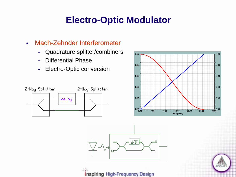
!! MachMach--Zehnder InterferometerZehnder Interferometer! Quadrature splitter/combiners! Differential Phase! Electro-Optic conversion
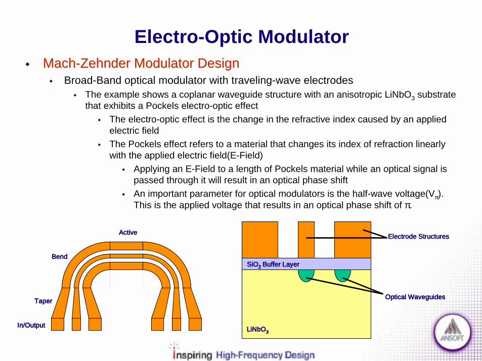
Electro-Optic Modulator!! MachMach--Zehnder Modulator DesignZehnder Modulator Design
! Broad-Band optical modulator with traveling-wave electrodes! The example shows a coplanar waveguide structure with an anisotropic LiNbO3 substrate
that exhibits a Pockels electro-optic effect! The electro-optic effect is the change in the refractive index caused by an applied
electric field! The Pockels effect refers to a material that changes its index of refraction linearly
with the applied electric field(E-Field)! Applying an E-Field to a length of Pockels material while an optical signal is
passed through it will result in an optical phase shift! An important parameter for optical modulators is the half-wave voltage(Vπ).
This is the applied voltage that results in an optical phase shift of π.
SiOSiOSiOSiO2222 Buffer LayerBuffer LayerBuffer LayerBuffer Layer
Electrode StructuresElectrode StructuresElectrode StructuresElectrode Structures
LiNbOLiNbOLiNbOLiNbO3333
Optical WaveguidesOptical WaveguidesOptical WaveguidesOptical Waveguides
ActiveActiveActiveActive
BendBendBendBend
TaperTaperTaperTaper
In/OutputIn/OutputIn/OutputIn/Output

Electro-Optic Modulator
!! ElectroElectro--Optical Modulator DesignOptical Modulator Design
! The design of the electrodes is critical for optimal performance! Speed of the modulator is limited by the electrical capacitive effects! Velocity of the Electrical and Optical signals must be matched! The length of the Active region or Interaction length is critical
! Demands precise modeling and control of Microwave propagation characteristics! Evaluation of Frequency dispersion for:
! Microwave effective index! Characteristic Impedance! Attenuation Constant
! Evaluation of Electrical performance for:! Finite electrode thickness and conductivity! Metalization undercutting! SiO2 buffer layer

Vector EVector EVector EVector E----Field PlotField PlotField PlotField Plot
Complex Magnitude of the Electric FieldComplex Magnitude of the Electric FieldComplex Magnitude of the Electric FieldComplex Magnitude of the Electric Field
Ansoft HFSS is used to calculate the Ansoft HFSS is used to calculate the Ansoft HFSS is used to calculate the Ansoft HFSS is used to calculate the Field Solution inside the conductorsField Solution inside the conductorsField Solution inside the conductorsField Solution inside the conductors
Electro-Optic Modulator
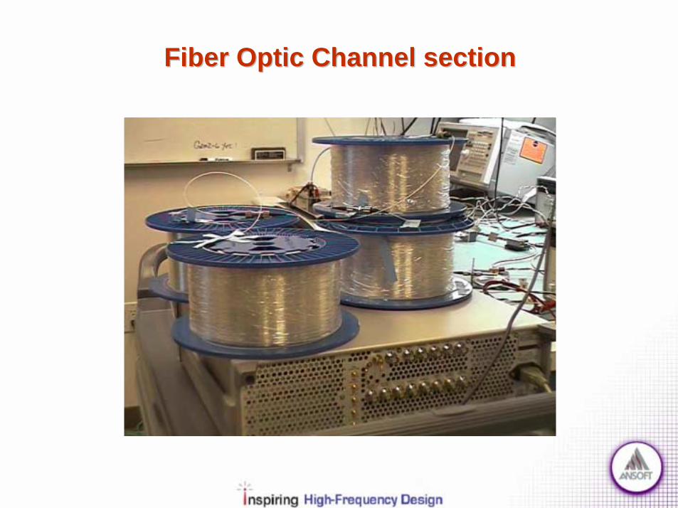
Fiber Optic Channel sectionFiber Optic Channel section

Fiber Optic Channel
!! Optical FiberOptical Fiber
! Fiber Types (SM, DSF, DCF)
! NLS Equation
! Dispersion Effects
! Nonlinear Effects
! Optimization

Optical Fiber!! Fiber TypesFiber Types
! Single Mode Fiber has energy centered in the core (LP01 mode)! Multi-Mode Fiber has a large core that support many propagation modes! DCF, DSF and NZDSF fibers types
!! Fiber ModesFiber Modes (See Appendix C for details)! Maxwell’s equations with variable permittivity! Electric field split into envelope and modal distributions! General Mode field distributions
!! Single mode conditionSingle mode condition
radiuscoreaknnakV
oo
o
_,/24.22
221
==<−⋅⋅=
λπ
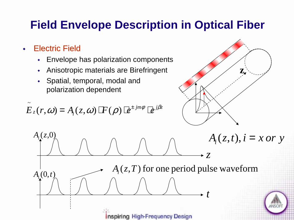
yorxitzAi ),,( =z
)0,(zAi
waveformpulse period onefor ),( TzAi
t
),0( tAi
!! Electric FieldElectric Field! Envelope has polarization components! Anisotropic materials are Birefringent! Spatial, temporal, modal and
polarization dependent
zjjmiz eeFzArE βφρωω ⋅⋅⋅= ±)(),(),(
~
Field Envelope Description in Optical Fiber
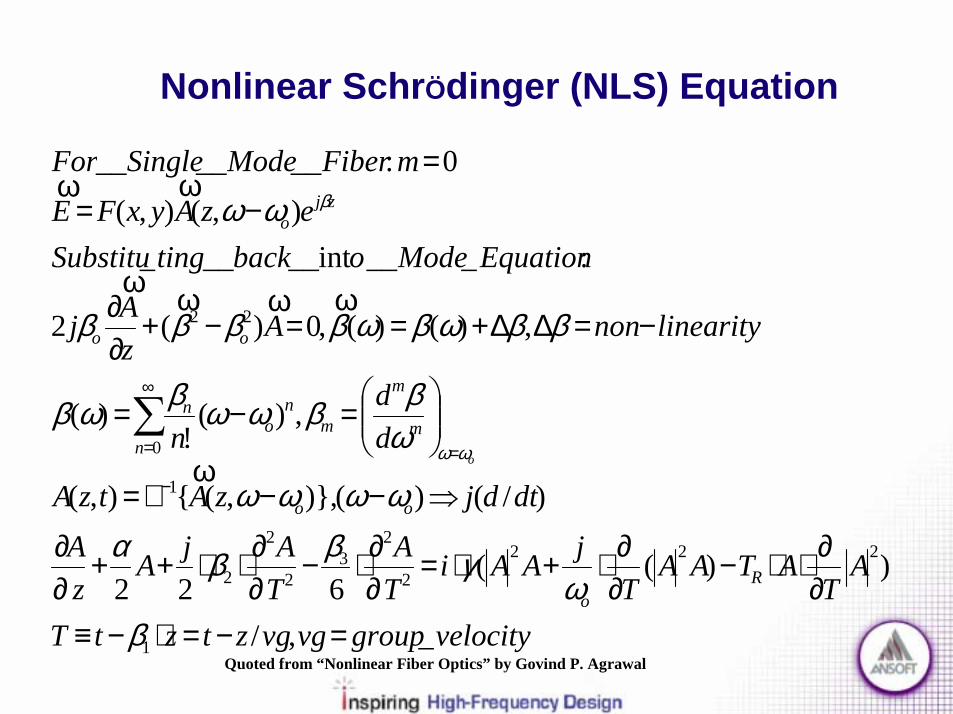
z

Nonlinear Schrödinger(NLS) Equation
velocitygroupvgvgztztT
AT
ATAAT
jAAiTA
TAjA
zA
Ro
_,/
))(( 6 22
1
2223
33
2
2
2
=−=⋅−≡∂∂⋅⋅−
∂∂⋅+⋅=
∂∂⋅−
∂∂⋅⋅++
∂∂
βω
γββα
!! NLS Equation (Fiber Wave Propagation)NLS Equation (Fiber Wave Propagation)! Derived from Maxwell’s equations! Solve to find the envelope function versus time and distance! α is the attenuation factor! β1 is the inverse of the group velocity! β2 is the group velocity dispersion factor! β3 is the third order dispersion factor! γ is the self phase modulation factor! γ/ωo is the self-steepening factor! Tr is the Raman scattering factor

Fiber Attenuation
!! Fiber LossFiber Loss! Attenuation! SMF Loss = 0.2dB/km at 1550nm
α⋅⋅= )(log10]/[ 10 ekmdBLoss
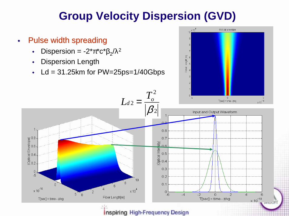
Group Velocity Dispersion (GVD)
!! Pulse width spreadingPulse width spreading! Dispersion = -2*π*c*β2/λ2
! Dispersion Length! Ld = 31.25km for PW=25ps=1/40Gbps
2
2
2β
odTL =

Third Order Dispersion (TOD)
!! Dispersion Induced OscillationsDispersion Induced Oscillations! Only occurs when GVD is very small! TOD Oscillations! TOD Length! Ld3 = 156,250km for PW=25ps
3
3
3β
odTL =
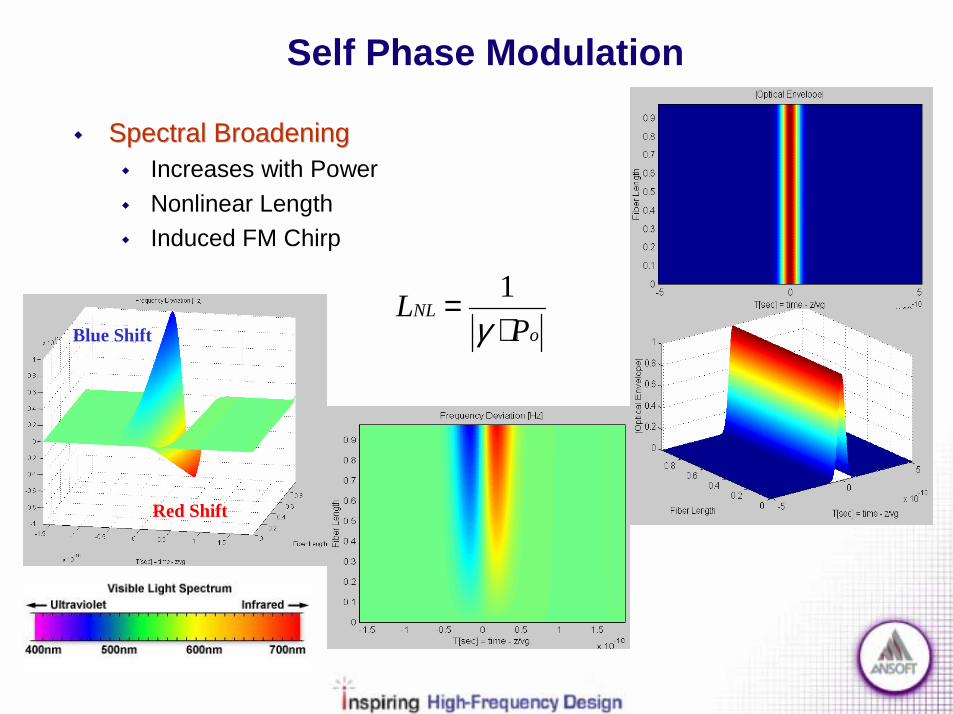
Self Phase Modulation
Blue Shift
Red Shift
!! Spectral BroadeningSpectral Broadening! Increases with Power! Nonlinear Length! Induced FM Chirp
oNL
PL
⋅=
γ1

Fiber Distortion Summary
!! AttenuationAttenuation
!! DispersionDispersion! Chromatic (GVD & TOD)! Polarization (PMD)
!! Phase distortionPhase distortion! Self Phase (SPM)! Cross Phase (XPM)
!! Nonlinear Energy TransferNonlinear Energy Transfer! Acoustic (SBS)! Electromagnetic (SRS)
!! Four Wave MixingFour Wave Mixing

Fiber Channel Optimization!! Loss ManagementLoss Management
! EDFA / Repeater
!! Dispersion CompensationDispersion Compensation! Normal / Anomalous GVD! Dispersion Length
!! NonNon--Linear DistortionLinear Distortion! Effective NL length! Max Power! Channel Spacing
!! NoiseNoise! Filters / Isolators! Repeaters
oNLodod
PLTLTL
⋅===
γββ1,,
3
3
32
2

Optical Devices SectionOptical Devices Section

Optical Devices
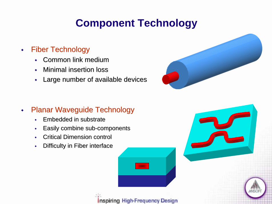
!! Component TechnologyComponent Technology!! FiberFiber!! Planar WaveguidePlanar Waveguide
!! Optical Amplifier (EDFA)Optical Amplifier (EDFA)! Optical versus Electrical! Physical Mechanism! Amplifier Topology
!! Passive OpticalPassive Optical! Filters! Splitters/Couplers! OXCs/OADMs! Circulators/Isolators
Component Technology
!! Fiber TechnologyFiber Technology!! Common link mediumCommon link medium!! Minimal insertion lossMinimal insertion loss!! Large number of available devicesLarge number of available devices
!! Planar Waveguide TechnologyPlanar Waveguide Technology!! Embedded in substrateEmbedded in substrate!! Easily combine subEasily combine sub--componentscomponents!! Critical Dimension controlCritical Dimension control!! Difficulty in Fiber interfaceDifficulty in Fiber interface

Optical Amplifier
!! Erbium Doped Fiber Amplifier (EDFA)Erbium Doped Fiber Amplifier (EDFA)! Replace expensive electro-optic repeaters! Purely optical in 1525nm-1565nm range! Amplified Spontaneous Emission (ASE) - Noise! Pump wavelength of 980nm
Pump Laser980nm or 1490nm
Input Signal1.53µm-1.57µm
Amplified Output SignalErbium doped fiber

Optical Amplifier
!! Optical versus Electrical AmplifierOptical versus Electrical Amplifier! Gain saturation
! Soft relaxation time! Inter-Modulation Distortion
! Only electrical amps! Noise Figure
! NF = SNRin / SNRout! Interface issues
! Matching networks! Stability
! Optical Isolator at output! Electrical feedback
! Failure! Optical pass through! Electrical open
1525-1565nm
980n
m
1480
nm
τ ~ 10ms
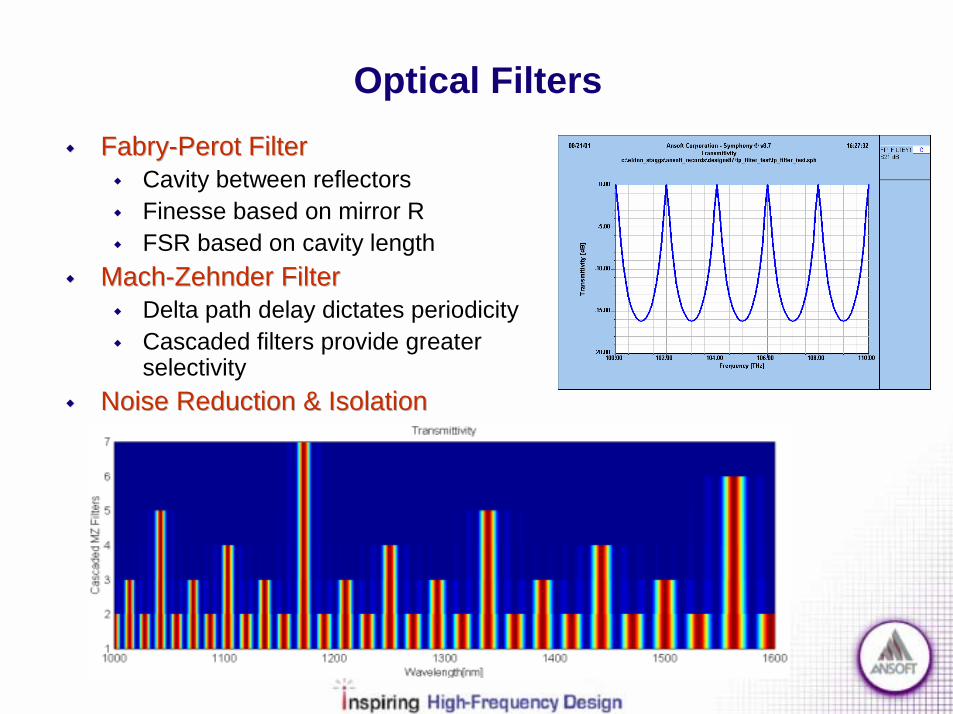
Optical Filters!! FabryFabry--Perot FilterPerot Filter
! Cavity between reflectors! Finesse based on mirror R! FSR based on cavity length
!! MachMach--Zehnder FilterZehnder Filter! Delta path delay dictates periodicity! Cascaded filters provide greater
selectivity!! Noise Reduction & IsolationNoise Reduction & Isolation

Passive Optical Elements
!! Splitters / CouplersSplitters / Couplers! Signal monitoring! Broadcasting
!! OADMsOADMs//OXCsOXCs! Network link! Network switch
Coupling Length
Cores
Cladding
Gap
λ1
λ2
λ2
λ1
λ1
λ1, λ2,…
λ1a
λ1a, λ2,…

Passive Optical Elements
!! Circulators/IsolatorsCirculators/Isolators! Bi-directional system! Reflection suppression
!! InIn--Fiber Bragg GratingsFiber Bragg Gratings! Wavelength selector! Many configurations
! Filter! Dispersion Compensator! In-Fiber laser
Braggn Λ⋅= 2λ
Non-selectedwavelengths
Input Signal
Selected Wavelength

ElectroElectro--Optical Receiver SectionOptical Receiver Section

Electro-Optical Receiver!! PhotodetectorPhotodetector
! Convert optical power to electrical current! PIN / APD diode! Shot & Thermal Noise
!! TransTrans--Impedance AmplifierImpedance Amplifier! Convert current to voltage! Amplify small receiver signal
!! Packaging (BGA) & SubstratePackaging (BGA) & Substrate! Parasitic Effects! Coupling Effects
!! SynchronizationSynchronization! Normalize & Digitize! Clock/Data Recovery
!! Baseband DemodulationBaseband Demodulation
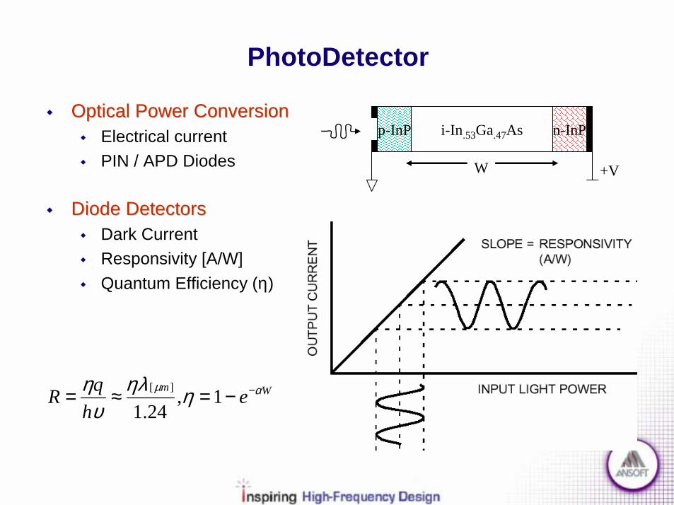
PhotoDetector
!! Optical Power ConversionOptical Power Conversion! Electrical current! PIN / APD Diodes
!! Diode DetectorsDiode Detectors! Dark Current! Responsivity [A/W]! Quantum Efficiency (η)
Wm eh
qR αµ ηηλυ
η −−=≈= 1,24.1
][
p-InP i-In.53Ga.47As n-InP
W +V

PhotoDetector
!! Diode Detectors (Cont’d)Diode Detectors (Cont’d)! Wavelength Range! Bandwidth
!! NoiseNoise! Thermal noise! Shot Noise! APD gain
CpRsRvWBW
LRCdrifttr
RCtr
)(,))(2/(1+==
+=ττ
ττπ

!! Functional ModelFunctional Model! Current Controlled Voltage Source! Feedback provides sensitivity! Feedback improves bandwidth! Amp gain improves response time
Trans-Impedance Amplifier
GainLoopOpenTTZZ ampinin __,/ =≈

Trans-Impedance Amplifier
!! TechnologyTechnology! Large Gain-Bandwidth product needed for 40Gbps! III-V HBTs (GaAs, InP) (fT = 250 GHz, fmax = 800 GHz)
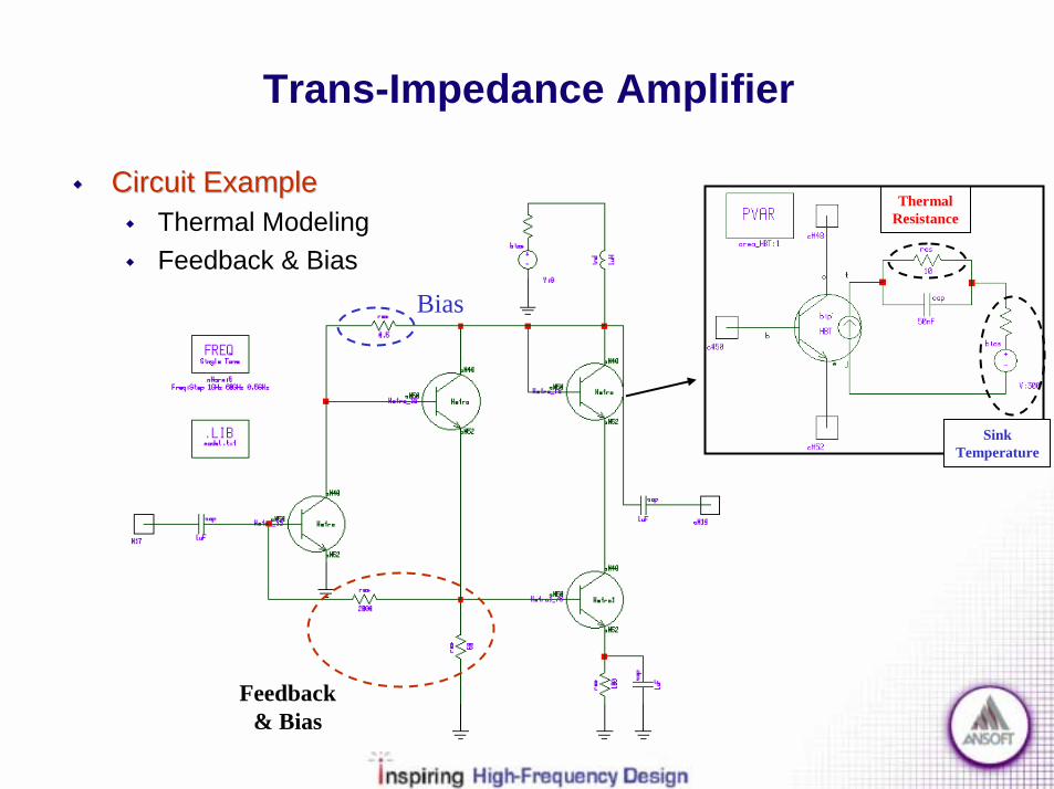
Trans-Impedance Amplifier
!! Circuit ExampleCircuit Example! Thermal Modeling! Feedback & Bias
Feedback& Bias
Bias
SinkTemperature
ThermalResistance

!! TransTrans--Impedance GainImpedance Gain! Broadband
Trans-Impedance Amplifier
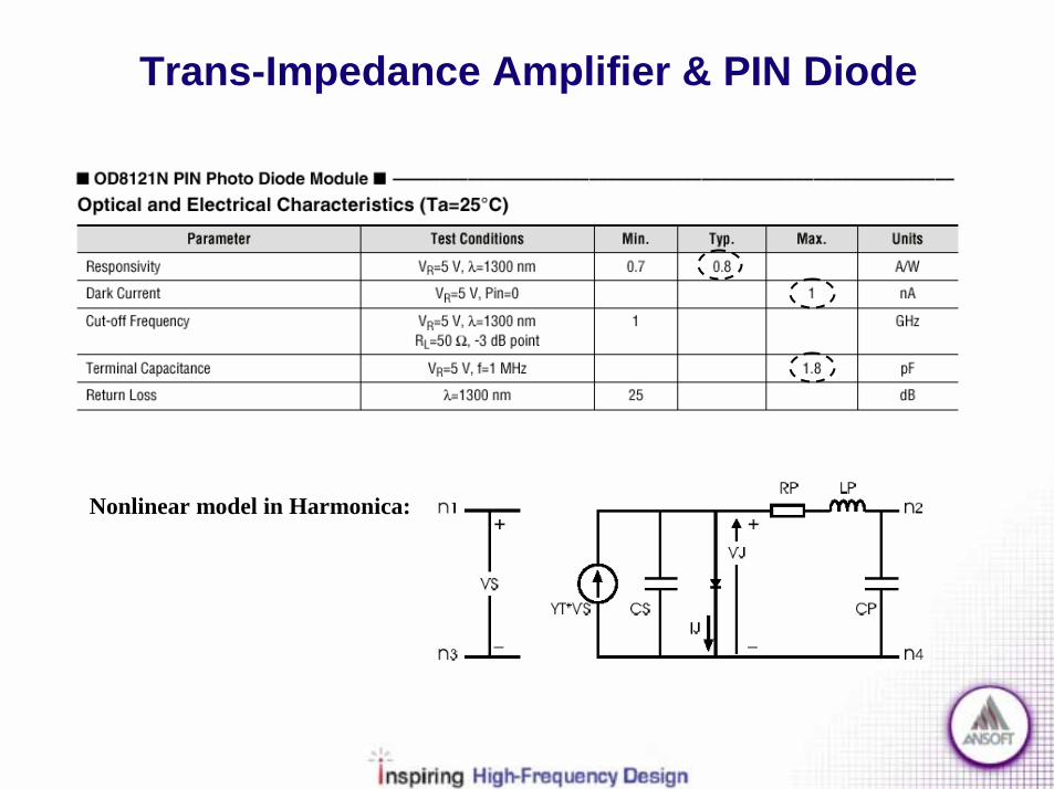
Trans-Impedance Amplifier & PIN Diode
Nonlinear model in Harmonica:

Term=106
PIN DiodeWith
Reverse Bias
Trans-Impedance Amplifier & PIN Diode
!! Addition of PhotodiodeAddition of Photodiode! Reverse Bias! Bandwidth impact

Trans-Impedance Amplifier & PIN Diode
!! TransTrans--Impedance GainImpedance Gain! Reactive matching

BGA Package design courtesy of ConnectCom MicroSystemsConnectCom MicroSystemsConnectCom MicroSystemsConnectCom MicroSystems Inc.
ConnectCom MicroSystemsConnectCom MicroSystemsConnectCom MicroSystemsConnectCom MicroSystems Inc. is a Venture Capital backed Internet Chip Company. It designs and manufactures ultra-low power, very high-speed analog and mixed-signal integrated circuits (ICs). These ICs enable and support terabit optical switching equipment and networks that form the new backbone infrastructure for the exploding Internet traffic.
ConnectComConnectComConnectComConnectCom employs innovative and patented designs techniques that are technology independent; to achieve power savings of up to 70% over traditional solutions for standards compliant SONET and SDH based applications. This will allow the company to offer superior, predictable economies, reliability and flexibility to the system designers of switch fabrics, DWDM equipment and optical modules.
CORPORATE OVERVIEWCORPORATE OVERVIEW

BGA: Critical Net Design! Ansoft HFSS, Full-Wave Spice, and Symphony provide
high-speed package designers the ability to characterize individual components or entire systems
! Full-Wave Spice and Symphony bridge the gap between frequency- and time-domain simulation
! Integration with industry standard layout tools provides a clean design flow from layout to analysis to production
ViaViaViaVia
Solder Solder Solder Solder BallsBallsBallsBalls
Ground Ground Ground Ground NetNetNetNet
Signal NetSignal NetSignal NetSignal Net
PowerPowerPowerPower

BGA: Design Integration
AnsoftLinksAnsoftLinksAnsoftLinksAnsoftLinks
3D Physical3D Physical3D Physical3D PhysicalModelModelModelModel
APDAPDAPDAPDAllegroAllegroAllegroAllegroEncoreEncoreEncoreEncoreZukenZukenZukenZuken
IGES, STEP, GDSII,IGES, STEP, GDSII,IGES, STEP, GDSII,IGES, STEP, GDSII,ACIS, DXF, AutoCADACIS, DXF, AutoCADACIS, DXF, AutoCADACIS, DXF, AutoCAD
Ansoft HFSSAnsoft HFSSAnsoft HFSSAnsoft HFSS

BGA: Simulation Results

BGA: Field Plots
Surface Current
E-Field on Surface of Core

BGA: Time-Domain Analysis
! Full-Wave Spice generates broad-band SPICE sub-circuits
! Supports Ansoft Maxwell Spice, PSPICE, or HSPICE
CrosstalkCrosstalkCrosstalkCrosstalkInput/OutputInput/OutputInput/OutputInput/Output
FullFullFullFull----Wave SpiceWave SpiceWave SpiceWave Spice

BGA: TDR Simulations

BGA:Eye Diagrams

BGA: BER

Signal Conditioning
!! AGC / LimiterAGC / Limiter! Normalize average gain variation! Protect follow on circuitry
!! Matched FilterMatched Filter! Digitize signal with ADC! Digital filter matched to transmitter! Minimizes out of band noise

Synchronization
!! Phase Lock LoopPhase Lock Loop! Pilot sequence! Over sample and detect edges! Provides data alignment
!! IntegrateIntegrate! Sum over a symbol period! Normalize output

Synchronization & Demodulation
!! Baseband DemodulationBaseband Demodulation! Invert the modulation scheme! Threshold detection for NRZ & RZ! Polybinary requires modulo-2
detection
Conclusions SectionConclusions Section

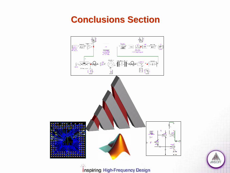
Conclusions!! System LimitationsSystem Limitations
! Loss Amplifier/Repeater stages! Dispersion DSF/DCF fiber use! Nonlinearity Unequal channel spacing! Noise Repeaters & Filters
!! Tools UsedTools Used! Symphony/Matlab System Level Simulation! Harmonica Circuit Level Simulation! HFSS Physical Level Simulation
!! System OptimizationSystem Optimization! Simulation needed for practical realization! Break design into smaller pieces
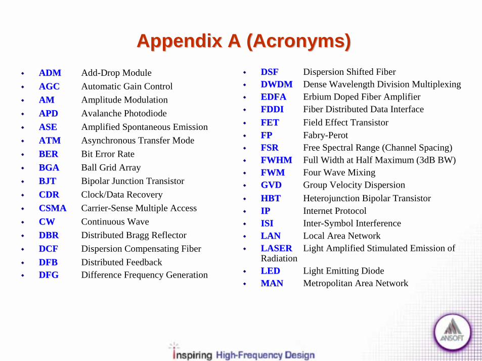
Appendix A (Acronyms)Appendix A (Acronyms)!! ADMADM Add-Drop Module!! AGCAGC Automatic Gain Control!! AMAM Amplitude Modulation!! APDAPD Avalanche Photodiode!! ASEASE Amplified Spontaneous Emission!! ATMATM Asynchronous Transfer Mode!! BERBER Bit Error Rate!! BGABGA Ball Grid Array!! BJTBJT Bipolar Junction Transistor!! CDRCDR Clock/Data Recovery!! CSMACSMA Carrier-Sense Multiple Access!! CWCW Continuous Wave!! DBRDBR Distributed Bragg Reflector!! DCFDCF Dispersion Compensating Fiber!! DFBDFB Distributed Feedback!! DFGDFG Difference Frequency Generation
!! DSFDSF Dispersion Shifted Fiber!! DWDMDWDM Dense Wavelength Division Multiplexing!! EDFAEDFA Erbium Doped Fiber Amplifier!! FDDIFDDI Fiber Distributed Data Interface!! FETFET Field Effect Transistor!! FPFP Fabry-Perot!! FSRFSR Free Spectral Range (Channel Spacing)!! FWHMFWHM Full Width at Half Maximum (3dB BW)!! FWMFWM Four Wave Mixing!! GVDGVD Group Velocity Dispersion!! HBTHBT Heterojunction Bipolar Transistor!! IPIP Internet Protocol!! ISIISI Inter-Symbol Interference!! LANLAN Local Area Network!! LASERLASER Light Amplified Stimulated Emission of
Radiation!! LEDLED Light Emitting Diode!! MANMAN Metropolitan Area Network
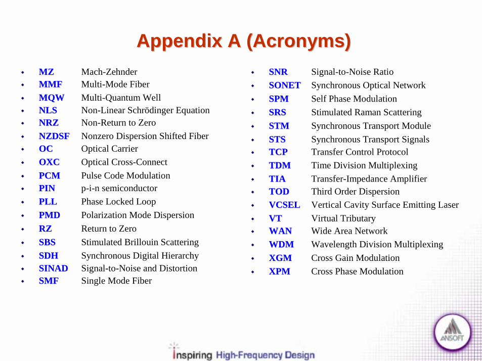
Appendix A (Acronyms)Appendix A (Acronyms)!! MZMZ Mach-Zehnder!! MMFMMF Multi-Mode Fiber!! MQWMQW Multi-Quantum Well!! NLSNLS Non-Linear Schrödinger Equation!! NRZNRZ Non-Return to Zero!! NZDSFNZDSF Nonzero Dispersion Shifted Fiber!! OCOC Optical Carrier!! OXCOXC Optical Cross-Connect!! PCMPCM Pulse Code Modulation!! PINPIN p-i-n semiconductor !! PLLPLL Phase Locked Loop!! PMDPMD Polarization Mode Dispersion!! RZRZ Return to Zero!! SBSSBS Stimulated Brillouin Scattering!! SDHSDH Synchronous Digital Hierarchy!! SINADSINAD Signal-to-Noise and Distortion!! SMFSMF Single Mode Fiber
!! SNRSNR Signal-to-Noise Ratio!! SONETSONET Synchronous Optical Network!! SPMSPM Self Phase Modulation!! SRSSRS Stimulated Raman Scattering!! STMSTM Synchronous Transport Module!! STSSTS Synchronous Transport Signals!! TCPTCP Transfer Control Protocol!! TDMTDM Time Division Multiplexing!! TIATIA Transfer-Impedance Amplifier!! TODTOD Third Order Dispersion!! VCSELVCSEL Vertical Cavity Surface Emitting Laser!! VTVT Virtual Tributary!! WANWAN Wide Area Network!! WDMWDM Wavelength Division Multiplexing!! XGMXGM Cross Gain Modulation!! XPMXPM Cross Phase Modulation

Appendix B (Protocol Details)Appendix B (Protocol Details)

Fiber Distributed Data Interface
! FDDI (ANSI X3T12)! Dual Token Ring, Opposite directions! 4B/5B NRZ Encoding! 100Mbps = 125Mbaud*(4/5)

Ethernet
!! Ethernet (Ethernet (IEEE802.3IEEE802.3))! CSMA/CD scheme! 10Mbps (10Base-FL)! 100Mbps (100Base-FX)! 1Gbps (1000Base-SX,LX)
!! OSI LayersOSI Layers! MAC & PHY (no LLC)
!! Frame FormatFrame Format
Preamble DestAddr
SourceAddr Type Payload Postamble

Asynchronous Transfer Mode
!! Asynchronous Transfer Mode (ATM)Asynchronous Transfer Mode (ATM)! 53 Byte cells (48 Byte data sets = AAL + Data)! Service types: CBR, CVR and Data! Virtual Channels / Virtual Paths
Data + AAL(48B)
Header (5B)
UNI Header NNI Header
VCI
HEC
GFC VPI
VCI PT CLP
VPI VCI
VCI
HEC
VPI
VCI PT CLP
VPI VCI

Asynchronous Transfer Mode
!! ATM Adaptation LayerATM Adaptation Layer! AAL1 – Constant Bit Rate! AAL2 – Variable Bit Rate! AAL3/4 – Connection & Connectionless! AAL5 – IP Packets & Other
AAL1
AAL3/4
AAL2
AAL5 SAR-SDU (43B=344b)
ST(4b)
SN(4b)
RES/MID(10b)
SAR-SDU CRC(10b)
LI(6b)
SN(4b)
IT(4b)
SAR-SDU CRC(10b)
LI(6b)
SN(4b)
SNP(4b)
SAR-SDU
SAR-SDU = Data

Appendix C (Fiber Model Derivations)Appendix C (Fiber Model Derivations)

Nonlinear SchrÖdinger (NLS) Equation
iablevarcomplextE
cE
tEBB
tE
BDtDH
tBE
JFiberinAssume
BDtDJH
tBE
EquationssMaxwellEquationssMaxwellfromNLSofDerivation
rr
roo
_,
,
0,0,,
0,0:__
0,,,
:_'_'_____
2
2
22 =
∂∂⋅=∇
∂∂⋅⋅⋅=×∇×∇
∂∂−=×∇×∇
=⋅∇=⋅∇∂∂=×∇
∂∂−=×∇
==
=⋅∇=⋅∇∂∂+=×∇
∂∂−=×∇
εε
εωω
ωωωω
ωωωωωω
ω
ωωωωωωω
εµ
ρ
ρ

Nonlinear SchrÖdinger (NLS) Equation
Quoted from “Nonlinear Fiber Optics” by Govind P. Agrawal
zjjm
m
m
zjjm
ooorr
eeFzAE
knknaKbaJb
F
eZeenvelopepulseyingslowlyzA
zZFzAEsCoordinatelCylindricainiablesofseparationUse
kEkEEc
E
domainfrequencyinSolve
βφ
βφ
ρω
βγβκργρρκρ
ρ
ωφρω
λπω
)(),(
,,:)(:)(
)(
,_,____var__),(
)()()(),(:________var______
/2,0
:____
20
21
22220
21
2
2
1
222
22
=
−=−=
>⋅≤⋅
=
==Φ=
Φ=
==⋅⋅+∇=⋅⋅+∇
ω
ω
ωωωωεε
Nonlinear SchrÖdinger (NLS) Equation
Quoted from “Nonlinear Fiber Optics” by Govind P. AgrawalvelocitygroupvgvgztztT
AT
ATAAT
jAAiTA
TAjA
zA
dtdjzAtzA
dd
n
linearitynonAzAj
EquationModeobacktingSubstituezAyxFE
mFiberModeSingleFor
Ro
oo
m
m
mn
on
n
oo
zjo
o
_,/
))(( 6 22
)/()()},,({),(
,)(!
)(
,)()(,0)(2
:___int_____),(),(
0:______
1
2222
23
2
2
2
1
0
22
=−=⋅−≡∂∂⋅⋅−
∂∂⋅+⋅=
∂∂⋅−
∂∂⋅⋅++
∂∂
⇒−−ℑ=
=−=
−=∆∆+==−+∂∂
−=
=
−
=
∞
=∑
βω
γββαωωωω
ωββωωβωβ
ββωβωββββ
ωω
ωω
β
ω
ωωωω
ωω
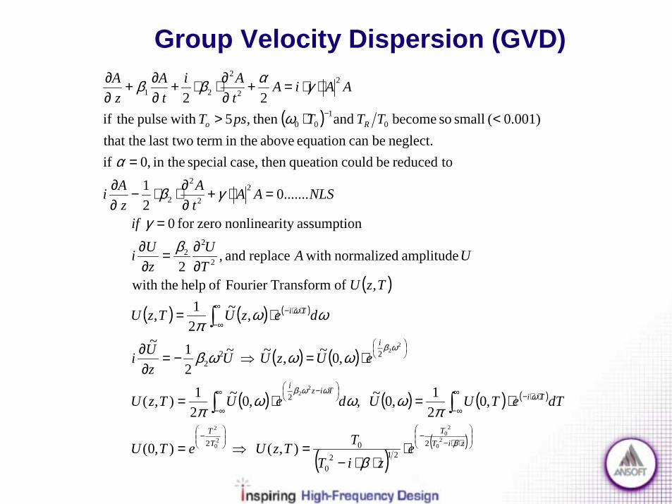
Group Velocity Dispersion (GVD)
( )
( )( ) ( ) ( )
( ) ( )
( ) ( ) ( ) ( )
( )( )
⋅⋅−−
−
⋅⋅−∞
∞−
−∞
∞−
⋅⋅−∞
∞−
−
⋅⋅⋅−
=⇒=
⋅=⋅=
⋅=⇒−=∂∂
⋅=
∂∂=
∂∂
=
=⋅+∂∂⋅⋅−
∂∂
=
<⋅>
⋅⋅=+∂∂⋅⋅+
∂∂+
∂∂
∫∫
∫
ziTT
TT
TiTizi
i
Ti
Ro
eziT
TTzUeTU
dTeTUUdeUTzU
eUzUUzUi
dezUTzU
TzU
UATU
zUi
if
NLSAAtA
zAi
TTTpsT
AAiAtAi
tA
zA
β
ωωωβ
ωβ
ω
β
πωωω
π
ωωωβ
ωωπ
βγ
γβ
α
ω
γαββ
20
20
20
2
22
22
2212
0
02
2
222
2
22
22
2
2
01
00
22
2
21
),( ),0(
,021,0~ ,,0~
21),(
,0~,~ ~21~
,~21,
, of Transform Fourier of help theth wi
amplitude normalized with replace and ,2
assumptionty nonlineari zerofor 0
.......0 2
1
toreduced be could queation thencase, special thein ,0 ifneglect. be can equation above thein termlast two that the
0.001)( small so become and then,5 withpulse theif2 2
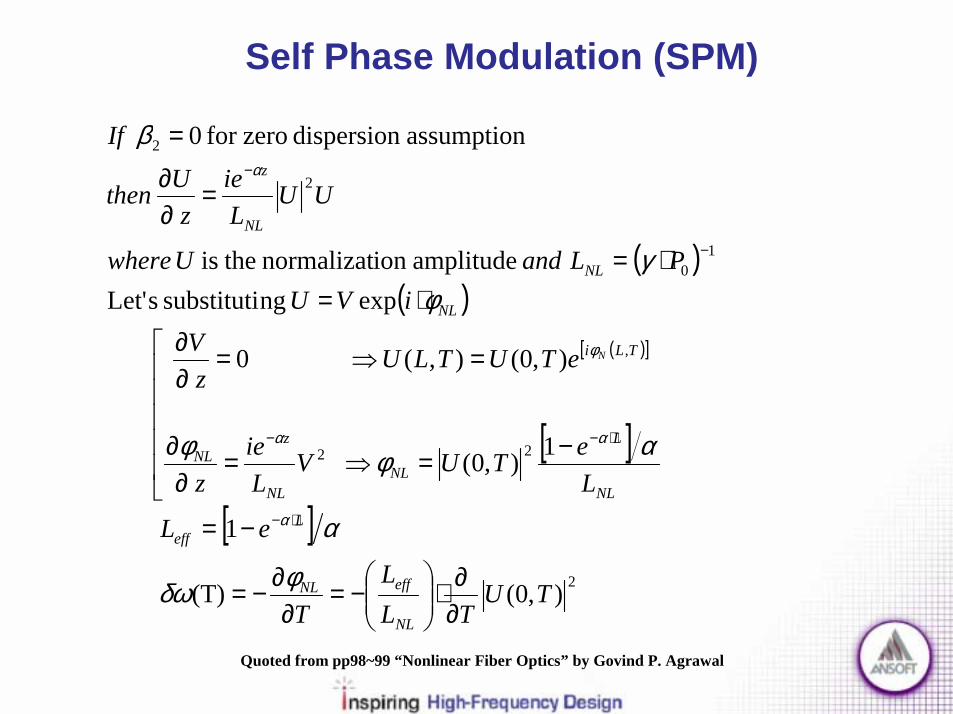
Self Phase Modulation (SPM)
( )( )
( )[ ]
[ ]
[ ]2
22
,
10
2
2
),0((T)
1
1),0(
),0(),( 0
exp ngsubstituti sLet' amplitudeion normalizat theis
assumption dispersion zerofor 0
TUTL
LT
eL
LeTUV
Lie
z
eTUTLUz
ViVU
PLandUwhere
UULie
zUthen
If
NL
effNL
Leff
NL
L
NLNL
zNL
TLi
NL
NL
NL
z
N
∂∂⋅
−=
∂∂−=
−=
−=⇒=∂
∂
=⇒=∂∂
⋅=⋅=
=∂∂
=
⋅−
⋅−−
−
−
φδω
α
αφφ
φγ
β
α
αα
φ
α
Quoted from pp98~99 “Nonlinear Fiber Optics” by Govind P. Agrawal

Appendix D (References)Appendix D (References)! Nonlinear Fiber Optics, 3rd Edition, Govind Agrawal
! Fiber-Optic Communication Systems, 2nd Edition, Govind Agrawal
! Digital Communications, Bernard Sklar
! Mathematical Methods for Physicists, 3rd Edition, Arfken
! Understanding Optical Communications, IBM Redbook, Harry Dutton
! Synchronous Optical Network, Tektronix App. Note
! Electronic Circuit Analysis, Colclaser, Neaman & Hawkins