foundation processor owner’s referencekrellonline.com/downloads/foundationprocessorowner... ·...
TRANSCRIPT
Foundation Processor OWNER’S REFERENCE

2
Foundation Processor Reference Surround Sound Preamp / Processor
© 2013 by Krell Industries LLC. All rights reserved.
THERE ARE NO USER-SERVICEABLE PARTS INSIDE ANY KRELL PRODUCT.
Please contact your authorized dealer, distributor, or Krell if you have any questions not addressed in this reference manual.
WARNING: Do not place the component where it could be exposed to dirt or excessive moisture.
The ventilation grids on the top and bottom of the Foundation Processor must be unobstructed at all times. Do not place flammable material on top of or beneath the component.
When making connections to this or any other component, make sure all components are off. Turn off all system power before connecting the Foundation Processor to any other component. Make sure all cable terminations are of the highest quality, free from frayed ends, short circuits or cold solder joints.
CONTACT INFORMATION: Krell Industries, LLC
45 Connair Road
Orange, CT 06477-3650 USA
TEL 203-799-9954
FAX 203-891-2028
E-MAIL [email protected]
WEBSITE http://www.krellonline.com
Krell® is a registered trademark of Krell Industries LLC., and is restricted for use by Krell Industries LLC., its subsidiaries, and authorized agents. All other trademarks and tradenames are registered to their respective companies.Manufactured under license under U.S. Patent Nos: 5,956,674; 5,974,380; 6,226,616; 6,487,535; 7,212,872; 7,333,929; 7,392,195;7,272,567 & other U.S. and worldwide patents issued & pending. DTS-HD, the Symbol, & DTS-HD and the Symbol together are registered trademarks & DTS-HD Master Audio is a trademark of DTS, Inc. © DTS, Inc. All Rights Reserved.
Manufactured under license from Dolby Laboratories. Dolby, Pro Logic, and the double-D symbol are trademarks of Dolby Laboratories.
3Foundation Processor
Table of Contents
Introduction (4)
Getting Started (5)
Front Panel and Remote Diagram (6)
Back Panel Diagram (7)
Connecting the Foundation to your System (8)
Initial Setup (9)
Speaker Set-up (10)
Source Set-up (11)
Audio Operation (12)
Network Set-up (13)
Diagnostic Mode (14)
Software Version and Update (14)
Restore Settings (14)
Save Settings (14)
Display Setup (14)
Operating the Foundation (15)
Foundation Processor Control (18)
Foundation Processor RS-232 Feedback (20)
Warranty (24)
Service (25)
Specifications (26)

4Foundation Processor
Introduction to the KRELL Foundation Processor
Thank you for your purchase of the Foundation Surround Sound Preamplifier/Processor. From decoding the latest lossless audio formats, extensive digital switching, 3DTV pass-through, and more, the Foundation is fully compliant with the digital age. Yet the 7.1-channel processor also features balanced audio outputs, automatic setup and room EQ, and Krell’s legendary robust hardware. A slim new form factor exudes the Krell aesthetic, while allowing placement in smaller equipment racks.
The heart of Krell surround sound preamp/processors is sound quality that is paired to the latest in surround processing technology. At the hub of the Foundation digital signal processing is a pair of dual core 32 bit Cirrus Logic CS497024 DSP’s performing 1.8 giga operations per second. Digital signals are then routed to 32 bit ESS Sabre DACS.
Based on award-winning preamplifier technology, all Foundation analog output stages are built to the same exacting standard and feature balanced and single-ended cable connections. Only Krell designed preamplifier circuitry is employed within every channel utilizing discrete current based Class A, direct coupled circuitry for the greatest signal purity and highest bandwidth. Performance robbing op amps or integrated circuits are not used anywhere in the audio path. Preamp mode bypasses all digital circuitry and routes analog stereo inputs directly to a balanced resistor ladder volume control for ultimate music reproduction.
In addition to 10 HDMI 1.4a inputs, the Foundation has 2 HDMI outputs, both of which feature Audio Return Channel. With ARC, a display device is able to send audio back down the HDMI cable to the processor. This is beneficial for those with televisions with built-in web streaming capability like Netflix or Pandora, so the streaming audio can use the full home theater system instead of just the TV’s speakers.
The Foundation passes video signals directly without any video processing, ensuring bit-for-bit accuracy of the signal, up to 1080p/60. However, to simplify cabling, setup, and use, there is full transcoding of the 2 composite and 3 component analog video inputs to the HDMI outputs.
The Foundation includes a new Krell development - Intelligent HDMI switching. Intelligent HDMI switching is a combination of circuitry and innovative software that optimizes HDMI operation. Various parameters including the monitor’s electronic ID and source video resolution are stored in non-volatile memory. All 10 source inputs are always active so source, channel, video resolution, and audio format changes are instantaneous. The Intelligent HDMI design provides the fastest signal recognition possible.
Krell designed the Foundation with flexibility and ease-of-use in mind, with extensive routing capability of the audio inputs to the various outputs. During setup, the specific paths will be chosen based on how the user intends to use each source, displays, and audio output channels.
The Foundation will allow owners to take full advantage of the best audio soundtracks available, with decoding of Dolby Digital, Digital Plus, Dolby TrueHD, DTS, DTS-ES Discrete, Matrix, and DTS-HD Master Audio. In addition, a full suite of post-processing modes are included, including Dolby Pro Logic IIx and DTS Neo 6. Krell’s proprietary surround modes, Party, General Admission, Front Row, and On Stage, offer a different way to listen to favorite tracks.
The Foundation also features Krell’s Automatic Room Equalization System (ARES), to ensure the best possible performance from every theater. ARES analyzes all the speakers in the system, their location, phase, and distance from each other, to determine the best crossover frequency, delay, and more. In addition, ARES incorporates the acoustics of the room to determine unique EQ curves for each of the 7.1 output channels. Unlike other room EQs, ARES can be programmed to only adjust the troublesome low frequencies, leaving high frequencies unaltered.
To allow full integration into a home automation system, the Foundation has Ethernet control, RS-232, 4 12v triggers ([email protected] and 2@60mA), and RC-5.

5Foundation Processor
Getting Started
Unpacking and Placement
The Foundation Processor is a precision instrument and should be handled with the utmost care when deciding where it is to be placed and while it is being unpacked and finally installed. Makes sure installation location is dry and level, and able to provide adequate ventilation. The Foundation Processor runs warm to the touch and requires the bottom and top of the unit be free from obstruction with good circulation of air. Allow a minimum of 3 inches above the unit for proper ventilation. Additional ventilation may be required when the unit occupies the same space with other electronics that generate heat like power amplifiers. Please consult an authorized KRELL dealer or KRELL industries to insure proper installation guidelines.
1. Accessories included
A. 1 AC Power cord
B. 1 Handheld Remote control
C. 1 Trigger cable
D. 1 CD w/ Owner’s reference
E. 1 Warranty registration card
F. 2 AAA Batteries
G. 1 T-10 torx wrench
AC Power Guidelines
The Foundation Processor is designed to work all over the world. The operating voltage is determined at the factory and is specifically set to operate in the country of final destination. The Foundation Processor requires good clean power and doesn’t require additional filtration.
NOTE: The Foundation Processor may not operate correctly when AC regeneration or voltage conversion devices are utilized.
6Foundation Processor
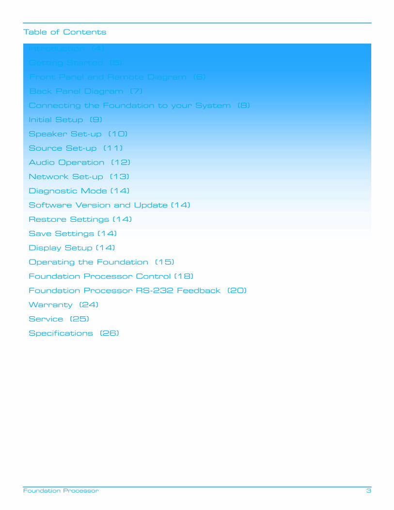
Front Panel and Remote Diagram
1
8
2
3
4 7
5 6
10 9
1
5
14
12
13
11
1615
6
7
23
4
1 Power Standby Button
2 Volume/Navigation Up/Down Button
3 Left/Right Navigation Button
4 Enter Button
5 Source Select Button(s)
6 Surround Mode Select Button
7 Menu Button
8 Front Panel HDMI Input
9 IR Receiver Window
10 ARES Microphone Input
11 Balance Button
12 Krell CD Transport Button
13 Dynamic Range Select Button
14 Channel Adjust Buttons
15 Zone Select Buttons
16 Mute Button
7Foundation Processor
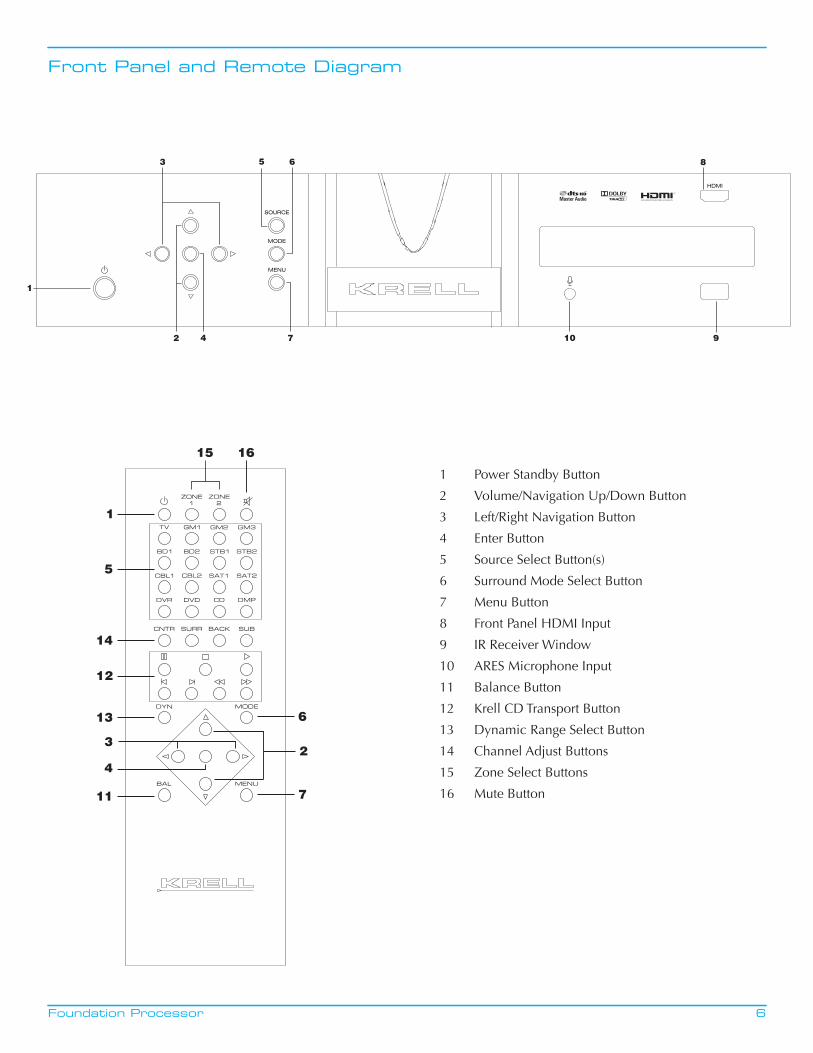
Back Panel Diagram
21
45
36
7
98
10
11
12
13
14
15
16
17
19 18
1 H
DM
I Vid
eo Im
puts
2 H
DM
I Vid
eo O
utpu
ts
3 M
ini U
SB
4 O
ptic
al D
igita
l Inp
uts
5 C
oaxi
al D
igita
l Inp
uts
6 M
ain
Pow
er S
witc
h
7 A
C P
ower
Cor
d R
ecep
tacl
e
8 Et
hern
et R
J-45
Jack
9 12
v Tr
igge
r In
put
10
12v
Trig
ger
Out
puts
11
RS-
232
Con
trol
Por
t
12
RC
-5 C
ontr
ol P
ort
13
Bal
ance
d A
udio
Out
puts
14
Sing
le-e
nded
Aud
io O
utpu
ts
15
Zon
e 2
Ana
log
Out
puts
16
Bal
ance
d A
nalo
g In
puts
17
Sing
le-e
nded
Ana
log
Inpu
ts
18
Com
pone
nt V
ideo
Inpu
ts
19
Com
posi
te V
ideo
Inpu
ts
Foundation Processor
Connecting the Foundation to Your System
8
The Foundation is equipped with 10 HDMI inputs, 3 component video inputs, and 2 composite inputs. We recommend that you use the HDMI connections to the Foundation, wherever the video source and video monitor both feature HDMI connections.
Video outputs include 2 HDMI outputs. Both HDMI outputs include Audio Return Channel. Audio Return Channel transfers audio from a TV back to the Foundation processor allowing TV audio listening through your home theater system. The TV must be equipped with Audio Return Channel functionality for this feature to work.
This section provides information about connecting the Foundation to your system.
Follow these steps to connect the Foundation to your system:
1. Make sure all power sources and components are off before connecting inputs and outputs.
2. Neatly arrange and organize wiring to and from the Foundation and all components. Separate AC wires fromaudio cables to prevent hum or other unwanted noise from being introduced into the system.
The Foundation is equipped with balanced and single ended inputs. Krell recommends using balanced interconnect cables. Balanced interconnect cables not only can minimize sonic loss but also are immune to induced noise, especially for installations using long cables. Balanced connections have 6 dB more gain than single ended connections. When level matching is critical, keep this specification in mind. Krell recommends that you use balanced inputs for components that will use the preamp mode.
For stereo analog input sources, connect the right and left outputs of your source components to the inputs on the Foundation. The Foundation is equipped with four sets of single-ended analog audio inputs (S-1 through S-4) via RCA connectors and one set of balanced analog audio inputs via XLR connectors.
The Foundation is equipped with three coaxial digital audio inputs via RCA connectors and three digital EIAJ optical inputs via TosLink connectors. Connect the digital audio output of your source components to the digital inputs on the Foundation.
The Foundation is equipped with a second audio zone. Two different sources may be played simultaneously. Additional wiring is not required as all digital sources, including HDMI based audio, are fed to the Zone 2 analog outputs.
9Foundation Processor
Initial Setup
The Foundation processor features the Krell Automatic Room Equalization System (ARES) to assist in setting up the Foundation for optimal performance. The ARES system includes two operations, the speaker setup portion and the equalization portion. The speaker setup portion of ARES determines the array and position of each speaker in the system. From there, ideal values for speaker crossover, delays relative to the listening position and sound pressure levels are all set automatically.
The second half of ARES is equalization. ARES includes a sophisticated equalization system that calculates flat frequency response for the entire system. The equalization algorithm uses the previously calculated speaker setup data and acquired room characteristics to provide the ideal frequency curves for the speakers in the system.
Individual speaker setup parameters may be edited after the ARES system completes its initial calculations. The ARES equalization process may be run again after the edits have been made.
All configuration options are selected using the front panel display or via a web enabled device such as a PC or tablet. The Foundation and the web enabled device must be connected to the same network to use a web enabled device for setup.
Microphone Setup
Place the included microphone at the listening position close to ear level and away from any obstructions. Plug the microphone into microphone input on the Foundation front panel and proceed with setup.
Front Panel Setup
Press the Menu button on the front panel or the remote control. Navigating the set-up menu is accomplished by using a combination of the up, down, left, right, and enter buttons on the front panel or remote control.
Press the Enter button to select Speaker Setup.

10Foundation Processor
Speaker Setup
Run ARES Spkr Setup
Press the Enter button. The ARES system will send noise signals to all the speakers in the system to determine correct crossover, delay, and output settings. After ARES completes its process, the Foundation returns to the Speaker Setup menu. From there, speaker parameters may be adjusted in the Edit Settings menu or the Equalization part of the ARES system may be run.
Note: If the Foundation does not detect a particular speaker in your system, a message asking for confirmation will appear. This will help determine if a system has been connected properly.
Run ARES EQ Setup
Press the Enter button. Select the desired frequency range for the ARES system to evaluate and equalize. ARES can be configured to equalize the entire frequency range or only a smaller portion. For equalization to be applied only to lower frequencies, select the desired frequency and equalization will only be applied to that frequency and below. After selecting the desired range, press Enter. The ARES system will send noise signals to the speakers to determine proper equalization in order to achieve a flat frequency response for the desired frequency range.
Edit Settings
The Left and Right (L/R) speaker configuration is displayed. Press the Up or Down button to view other speakers in the system. To edit one of the parameters, press the Enter button, the cursor will start blinking at the Crossover field. Press the Right button to move the cursor to the field to be edited.
Press the Up or Down button to change the value. Press the Enter button to confirm any change and press the Left button to exit the Edit Settings menu. The Foundation will ask for which setup memory, 1, 2, or 3, the edits are to be applied. If the No option is selected, the Foundation will disregard any previously made edits.
Crossover frequency edits
To edit the crossover frequency, press the Right button while the cursor is blinking at the Limited field. Press the Up or Down button to change the value between Full Range, Limited, or None. To choose a crossover point, select Limited and then press the Right button. Press the Up or Down button to view the available frequencies. Press the Enter button to confirm any change.
Note: None is not an option for the L/R speakers. Left and Right speakers must be present.
Time Delay edits
To edit the delay time (in milliseconds) setting, press the Up or Down button to edit the time delay setting. ARES first determines which speaker is the greatest distance from the listening position and sets the time delay to 0ms. ARES then calculates the time delay setting between this speaker and the remaining speakers in the system. For the L/R, Ls/Rs, and Lb/Rb speaker pairs, ARES uses the averaged delay from each speaker to the furthest speaker in the system. For adjustments, each millisecond is equal to one foot of distance between speakers.
Output Level edits
To edit the output level, press the Right button while the cursor is blinking at the output field. Press the Up or Down button to increase or decrease the output level of each speaker.

11Foundation Processor
Source Setup
Press the Enter Button to enter the Source Setup sub menu. Use the Up or Down button to select the desired parameter to edit.
Assign Names
Press the Enter Button to see the first source, BD1: Bluray1. Press the Up or Down button to select a different source.
To edit the currently displayed source, press the Enter button and the cursor will begin flashing at the first character field. Use the Up or Down button to change character. Use the Right or Left button to move the blinking cursor to another character and repeat editing procedure. Press Enter to confirm change. Press the Up or Down button to select a different source and repeat editing process.
The edited name will appear when the Source button is pressed on the remote or front panel. The new source name will also appear on a web connected device. The factory default will continue to appear in other menus.
Press the Left button to return to the Source Setup Menu
Assign Input
Press the Up or Down button to select source to edit. Press the Enter button and Vid (video) field will start flashing. Press the Up or Down button to select desired video input.
Press the Right button to move cursor to Aud (Audio) field. Press the Up or Down button to select desired audio input.
Press the Enter button to confirm changes. Press the Up or Down button to select a different source to edit.
When finished, press the Enter button and then the Left button to return the Source Setup sub menu.
Assign Triggers
Press the Enter button and the Trigger field will start flashing. Press the Up or Down button to select trigger to edit.
Press the Right button to move cursor to the source field. Press the Up or Down button to select desired source.
Press the Right button to move cursor to the State field. Press the Up or Down button to either Off or On.
Press the Right button to move cursor to the Delay field. Press the Up or Down button to select the desired trigger time delay.
Press the Right or Left button to move the cursor to the Trigger field or Source field to edit additional parameters.
When finished, press the Enter button and then the Left button to return to the Source Setup sub menu.
Level Trim
The level trim allows for output adjustment between sources.
Press the Enter button and the source field will start flashing. Press the Up or Down button to select a different source to edit.
Press the Enter and the dB field will begin flashing. Press the Up or Down button to increase or decrease output.
Press the Up or Down button to select a different source to edit and repeat the editing process.
When finished, press the Enter button and then the Left button to return the Source Setup sub menu.
Assign Memory
Press the Enter button to enter the Assign Memory sub menu.
The first source, BD1: Bluray1, is displayed along with its assigned memory. Press the Up or Down button to select a different source or press the Enter Button and the Memory field will flash. Press the Up or Down button to change the memory setting. Press Enter to confirm setting. Press the Left button to return to the Source Setup sub menu.
12Foundation Processor
Audio Operation
Press the Enter button to enter the Audio Operation sub menu.
Dolby PLIIx Setup
Press the Enter button to enter the Dolby PLIIx sub menu.
CENTER WIDTH
The amount of center output signal can be spread to the left and right channel outputs. The adjustment range is from 0 (lowest) to 7 (highest, effectively mutes the center channel). Press the enter button and the cursor will start blinking. Press the Up or Down button to select the desired value.
Press the Enter button to confirm choice. Press the Up or Down Button to select another parameter to edit.
DIMENSION
The sound field can be moved toward the front or rear loudspeakers, to achieve a more suitable balance from all loudspeakers. The adjustment range is 0 (maximum surround) to 6 (maximum center). The default setting is 3 (neutral). Press the enter button and the cursor will start blinking. Press the Up or Down button to select the desired value.
Press the Enter button to confirm choice. Press the Up or Down Button to select another parameter to edit.
SURROUND MODE
Press the Enter button and the cursor will start blinking. Press the Up or Down button to select between Auto and Manual.
In Auto, the Foundation will engage Dolby Pro Logic IIx anytime an incoming signal is encoded with Dolby Pro Logic IIx. If the signal changes to a non Dolby Pro Logic IIx , the Foundation will revert to the new signal.
In Manual, the Foundation will not add the Dolby Pro Logic IIx decoding automatically. Pressing the Mode button on the remote control until Dolby Pro Logic IIx mode is displayed is the only way to engage Dolby Pro Logic IIx decoding.
Press the enter button to confirm choice and then press the left button to return to the Audio operation menu.
5.1 Surround Output
For 7.1 systems playing back 5.1 encoded content, the Foundation can duplicate the surround channel information in the back channels. The default setting is Surrounds Only. To change to the Surrounds + Backs option, press the Enter button and then the up button. Press the enter button to confirm the selection.
Lip Sync Delay
Lip Sync Delay is a useful tool for systems where the video and audio signals are out of sync. The audio signal needs to be delayed to match the video signal. The Lip Sync Delay range of values is 0 to 200ms. Press the Enter button to activate the Lip Sync Delay setting and then use the up button to adjust. Press the enter button to confirm the desired choice.
DTS Neo:6 Setup
Press the Enter button to enter the DTS Neo:6 sub menu.
DTS NEO: 6 derives a 6.0 signal from two-channel source material. The center gain adjusts the amount of center channel information present in the left and right loudspeakers. The adjustment range is 0 (no center channel information; wide sound field) to 5 (maximum level of center channel information subtracted from the left and right channels; narrow sound field). Press the enter button and the cursor will start blinking. Press the Up or Down button to select the desired value.
Press the Enter button to confirm choice. Press the Up or Down Button to select another parameter to edit.
Audio Operation Continued
13Foundation Processor
Dynamic Range
Press the Enter button and the Mode field will start flashing. Press the Up or Down button to select the desired Dynamic Range setting.
Max/Off is the default and provides maximum dynamic range
Normal/Auto uses any dynamic range information encoded into a source’s bit stream
Night/On applies 22dB worth of compression to all incoming signals.
Press the Enter button to confirm choice and then press the left button to return to the Audio operation menu.
EQ
EQ mode turns the ARES EQ on or off. Press the Enter button to enter the EQ sub menu. Press Enter and the Mode field will blink. Press the Up or Down button to select on or off.
Network Setup
Press the Enter button to enter the Network Setup sub menu. Press the up or down button to view the various network parameters. Press the Enter button to see the value for the displayed parameter.
IP Address: The default network discovery is DHCP. If the Foundation is connected to an active network, it automatically acquires an IP address. To enter an IP address manually, change the Foundation to Static IP operation. To change to Static IP operation, press the Enter button at the IP Address sub menu. Press the Up or Down button to change the setting to Static. Press the Enter button to display the IP address. Press the Right button to move the cursor to number to be edited. Press the Enter button again and the selected number of the IP Address will begin blinking. Use the Up or Down button to edit the IP Address value. Press the Enter button to confirm change. Press the Left or Right button to move the cursor to another number in the IP address and repeat editing process.
Use the same process to edit the other network settings.
Note: the MAC Address is a factory set value and is not user editable.
The Foundation processor operation and setup options are available from the built in web server. To use the web server, make sure to connect the Foundation to a network with internet access and acquire an IP address. The IP address can be found in the Network Setup sub menu. Press the Enter button twice to see the IP address of the unit. It should be similar to 192.168.1.009.
To access the web server, type yourIPaddress/krell/index.html into the web browser address bar. For the IP address above, the correct address to enter would be: 192.168.1.009/krell/index.html.
The Foundation control web page will now appear on your computer or tablet screen. Using your mouse or finger, follow the remote control or front panel instructions to operate the Foundation.
14Foundation Processor
Diagnostic Mode
Diagnostic mode is used for troubleshooting and is disabled as a default. Leave diagnostic mode disabled unless directed by Krell.
Software VersionPress the Enter button to view currently operating Foundation software
Software Update Press the Enter button to display the Software Update sub menu. Press the Up or Down button to select the method for updating the software. Press the Enter button to select and then the Enter button again to confirm.
Choose the USB option if the Foundation is not connected to the internet and software updates are to be performed by connecting a USB drive to the USB input on the rear panel of the Foundation.
Choose the Network option if the Foundation is connected to the internet. The Foundation will check the Krell update server to determine if a new software update is available.
Restore SettingsRestore Settings will return the Foundation to the original factory settings or to previously saved user settings. Press the Up or Down button to change to User. Press the Enter button to confirm selection. Press the Enter button again to return to factory or user saved settings. The Foundation will display various messages and will eventually return to the standby mode.
Save SettingsSave Settings will save all configuration settings in non volatile memory. Press the Enter button to begin saving process.
Display Setup
Backlight Timeout
Backlight Timeout turns off the front panel display after a period of inactivity. The default time setting is Disabled which keeps the display always illuminated. Timeout can be set between 15 and 120 seconds.
Contrast Setup
Three contrast levels are available with level 2 being the default. Press the Enter button to activate the level setting and then use the up or down button to adjust. Press the Enter button to confirm the desired choice.

15Foundation Processor
Operating the Foundation
After the Foundation is connected to sources and amplifiers, and the system is configured, the Foundation is ready for operation.
1. Insert the AC power cord into the IEC connector on the Foundation. Insert the other end into the AC wall receptacle.
2. Move the back panel power switch into the up (on) position.
3. The red stand-by LED behind the Krell logo plate illuminates.
4. Use either the front panel power button or the remote control power button to power on the Foundation.
The blue power LED behind the Krell logo plate illuminates. The Foundation is now in the operational mode.
5. Press a desired source button and the Volume Up and Down button to find a proper listening level.
6. To adjust individual channels, press the CNTR, SURR, BACK, or SUB button and then the Volume Up or Down button to find a proper listening level.
7. To mute all output, press the Mute button. Press the Volume Up or Down, or the Mute button again to unmute the output.
8. To access the dynamic range menu directly, press the DYN button on the remote control to view the Dynamic Range sub menu. Press the Up or Down button to view the available options.
Max/Off is the default and provides maximum dynamic range
Normal/Auto uses any dynamic range information encoded into a source’s bit stream
Night/On applies 22dB worth of compression to all incoming signals.
Press the Enter button to select the desired option and Press Enter to return to normal operation.
9. To adjust left to right balance, press the BAL button on the remote control. The Left and Right channels will be displayed. Press the Right button to shift the balance to the right channel in .5dB increments. Alternatively, press the left button to move cursor to the right channel. Press the Right button to shift the balance to the left in .5 dB increments. Press the BAL button again to return to normal operation.
10. To return to stand-by, press the front panel power button or power button again. Krell recommends that the back panel power switch remain up (on) at all times.
Signal Recognition
The Foundation automatically detects the following signals and automatically engages the appropriate operating mode for the following Dolby and DTS signals:
DOLBY TrueHD, DOLBY DIGITAL 5.1, DOLBY DIGITAL 2.0, DOLBY DIGITAL Plus, Dolby Digital EX, Dolby Pro Logic IIx, DTS-HD Master Audio, DTS-HD High Resolution Audio, DTS 5.1, Discrete ES Discrete 6.1, DTS ES Matrix 6.1.
Additional processing modes can be applied to DOLBY DIGITAL 5.1, DOLBY DIGITAL 2.0, DOLBY DIGITAL Plus, Dolby Digital EX, Dolby Pro Logic IIx, and DTS 5.1 incoming signals. Press the Mode button to cycle through the options available for each automatically detected signal.
Operating the Foundation Continued
16Foundation Processor
The additional processing modes are:
Dolby D 5.1
Dolby D 5.1 + SurEX, Dolby D 5.1 + PLIIx Movie, and Dolby D 5.1 + PLIIx Music
Dolby D 5.1 + SurEX creates six full-bandwidth output channels from 5.1-channel sources. This is done using a matrix decoder that derives three surround channels from the two in the original recording. For best results, Dolby Digital EX should be used with movie soundtracks recorded with Dolby Digital Surround EX. All modes listed under Dolby Digital EX, including the default mode you have selected, can be accessed using the Mode button.
Dolby Digital 2.0
Dolby D + PLIIx Movie and Dolby D + PLIIx Music
DTS 5.1
DTS 5.1 Movie and DTS 5.1 Music
PCM and analog modes
A variety of audio modes can be applied to conventional digital and analog signals. The processing modes are:
PREAMP
Select Preamp mode for listening to analog stereo signals with the Foundation operating as an analog stereo preamplifier. Preamp mode bypasses the Foundation’s digital circuitry and sends signals from the balanced or single-ended inputs directly to the analog stereo outputs.
STEREO
Select Stereo mode for conventional digital stereo signals. Use this mode to listen to conventional stereo digital signals through the left and right speakers. The Foundation will perform digital to analog conversion and send signals to the analog stereo outputs.
FULL RANGE + SUB
Select Full Range + Sub to play two channel content using the left and right speakers plus the subwoofer. This mode will ignore any crossover configurations and send full range signal to the left and right speakers plus low frequencies to the subwoofer(s).
DOLBY PLIIx MOVIE
The movie mode is the improved counterpart to the original Pro Logic decoder. It is the choice for the majority of Dolby Surround encoded material.
DOLBY PLIIx MUSIC
The music mode is for use with unencoded stereo music recordings. The music mode features dimension and center width controls, see PLII Control, on page XX, to enhance the music surround experience.
DTS Neo:6
DTS Neo:6 provides up to six full-band channels of information from stereo encoded material. 7.1 and 6.1 systems will derive six channels from the signal while 5.1 systems will derive five channels from the signal. DTS Neo:6 includes two modes: DTS NEO:6 CINEMA for two channel matrixed movie material and DTS NEO:6 MUSIC for stereo encoded music material.
Operating the Foundation Continued
17Foundation Processor
Additionally, the Krell Music Surround Modes simulate different soundfield experiences when listening to music. The table below lists the modes and the speakers that operate within each mode:
Krell Music Surround Modes and operating speakers
GENERAL ADMISSION L/R/S/RR
FRONT ROW L/R/S/RR
ON STAGE L/R/C/S/RR
ENHANCED STEREO L/R/C/S
ORCHESTRA L/R/C/S/RR
MEZZANINE L/R/C/S/RR
FULL RANGE + SUB L/R/S
MONOPHONIC C/S
PARTY L/R/C/S/RR
Two Zone Operation
The Foundation has two audio zones, main and zone 2. The main zone consists of the main viewing or listening area, and zone 2 consists of another listening area. You can select a digital or analog audio source to play in either or a video device in the main zone and an audio source for Zone 2.
The Foundation two-zone operation offers a number of listening options.
You can play both zones simultaneously, with the main zone playing a source in one part of the house and zone 2 playing a different (or the same) source in another part of the house.
Play both zones with the Foundation in the stand-by mode:
1. Press the power button until the blue power LED illuminates.
2. Press the input device selection button or button for the source you wish to play.
3. Begin playing the source and adjust the volume to your liking.
4. Press the Zone 2 button.
5. Press the source selection button or button for another source to play in zone 2. Or select the same input devicebutton if you want the same source to play in both zones.
6. Begin playing the source and adjust the volume to your liking.
RS-232 Code Set
1. Preparing for RS-232 Connectivity
TheFoundation can be controlled remotely via an RS-232 connection. All of the features and functions of the unit can be accessed via RS-232 command strings.
NOTE: The Foundation can only recognize the “1pwrz” command while in stand-by mode. This insures that the unit is energized and ready to accept command strings. Once the unit is active, then commands can be sent. Feedback can be received when the unit is in stand-by mode.
A. The Foundation and All Krell components require a straight non-nulling RS-232 cable.
2. Settings
The RS-232 protocol settings for status and control are as follows:
9600 Baud, 8 Data Bits, 1 Stop Bit, No Parity
3. DB-9 Pin-out
A. Data Carrier Detect
B. Received Data
C. Transmitted Data
D. Data Terminal Ready
E. Signal Ground
F. Data Set Ready
G. Request To Send
H. Clear To Send
I. Ring Indicator
Notes
A. The decode preferences are dependant on the source data, not all formats are available to every input stream.
Foundation Processor Control
18Foundation Processor
Foundation Processor Control Continued
19Foundation Processor
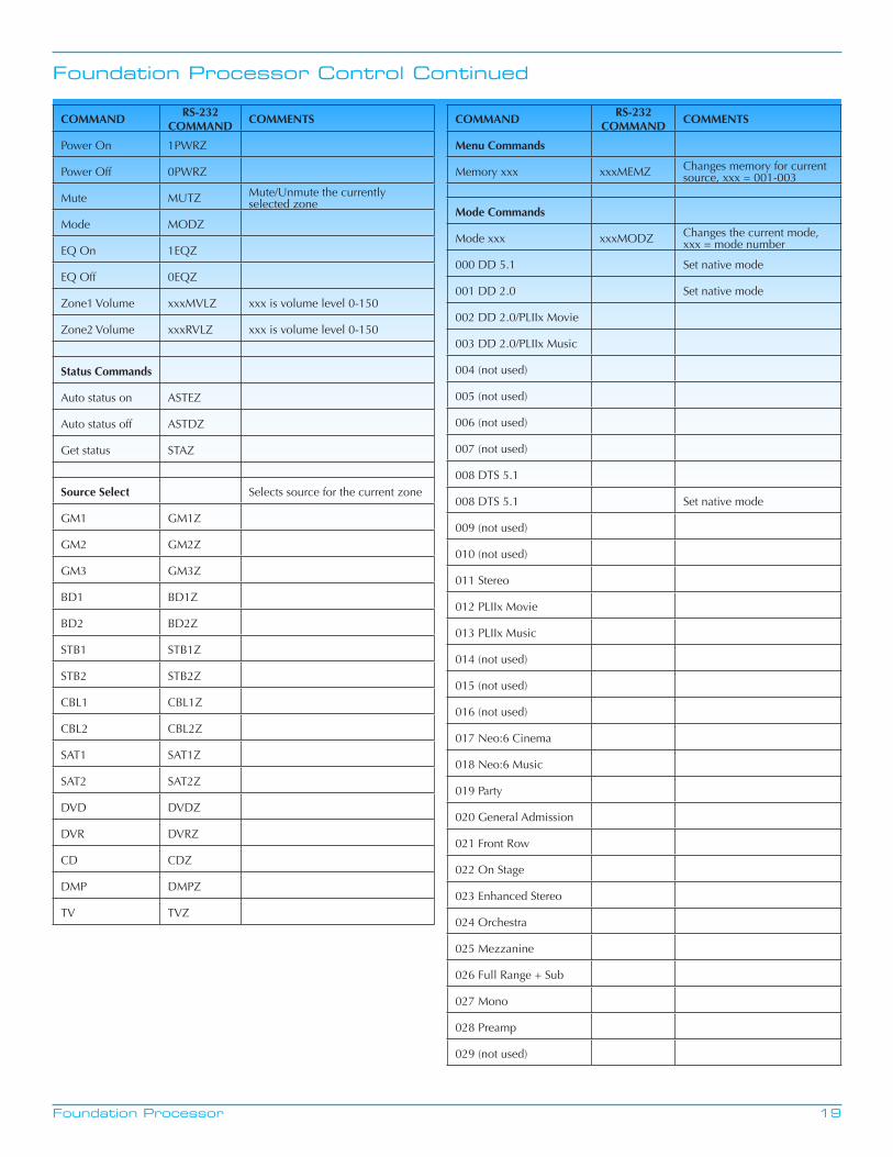
COMMANDRS-232
COMMANDCOMMENTS
Power On 1PWRZ
Power Off 0PWRZ
Mute MUTZ Mute/Unmute the currently selected zone
Mode MODZ
EQ On 1EQZ
EQ Off 0EQZ
Zone1 Volume xxxMVLZ xxx is volume level 0-150
Zone2 Volume xxxRVLZ xxx is volume level 0-150
Status Commands
Auto status on ASTEZ
Auto status off ASTDZ
Get status STAZ
Source Select Selects source for the current zone
GM1 GM1Z
GM2 GM2Z
GM3 GM3Z
BD1 BD1Z
BD2 BD2Z
STB1 STB1Z
STB2 STB2Z
CBL1 CBL1Z
CBL2 CBL2Z
SAT1 SAT1Z
SAT2 SAT2Z
DVD DVDZ
DVR DVRZ
CD CDZ
DMP DMPZ
TV TVZ
COMMANDRS-232
COMMANDCOMMENTS
Menu Commands
Memory xxx xxxMEMZ Changes memory for current source, xxx = 001-003
Mode Commands
Mode xxx xxxMODZ Changes the current mode, xxx = mode number
000 DD 5.1 Set native mode
001 DD 2.0 Set native mode
002 DD 2.0/PLIIx Movie
003 DD 2.0/PLIIx Music
004 (not used)
005 (not used)
006 (not used)
007 (not used)
008 DTS 5.1
008 DTS 5.1 Set native mode
009 (not used)
010 (not used)
011 Stereo
012 PLIIx Movie
013 PLIIx Music
014 (not used)
015 (not used)
016 (not used)
017 Neo:6 Cinema
018 Neo:6 Music
019 Party
020 General Admission
021 Front Row
022 On Stage
023 Enhanced Stereo
024 Orchestra
025 Mezzanine
026 Full Range + Sub
027 Mono
028 Preamp
029 (not used)
Foundation Processor RS-232 Feedback
20Foundation Processor
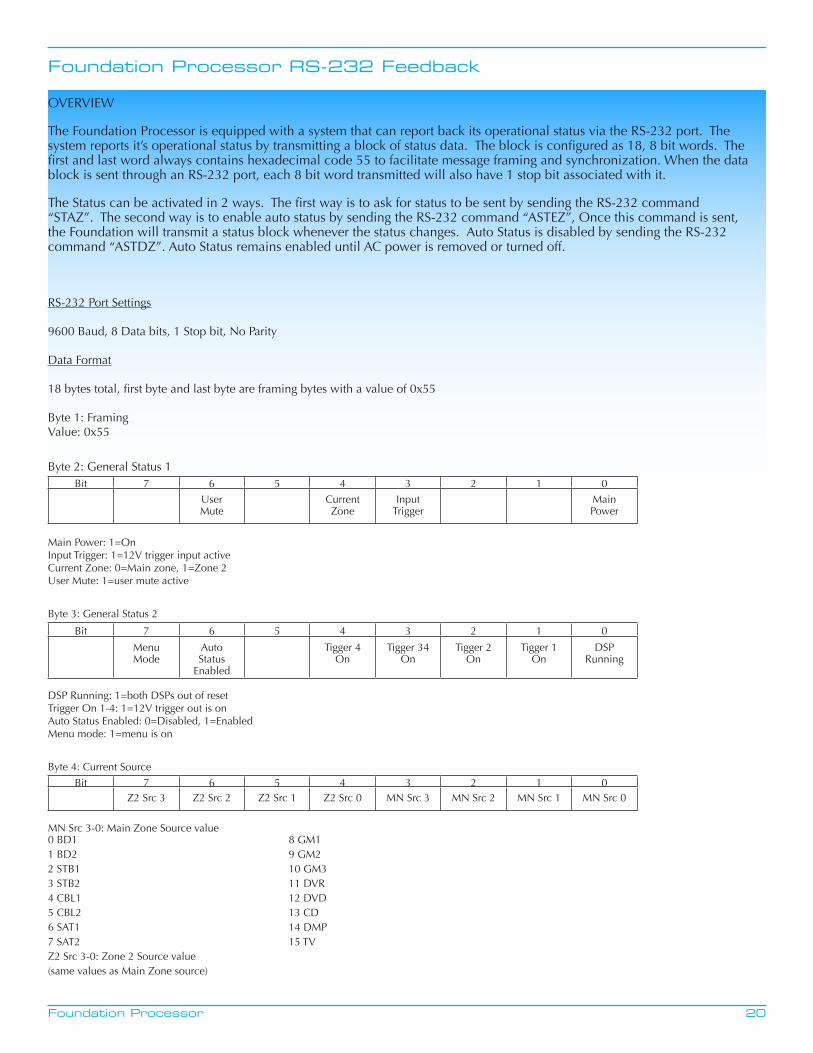
OVERVIEW
The Foundation Processor is equipped with a system that can report back its operational status via the RS-232 port. The system reports it’s operational status by transmitting a block of status data. The block is configured as 18, 8 bit words. The first and last word always contains hexadecimal code 55 to facilitate message framing and synchronization. When the data block is sent through an RS-232 port, each 8 bit word transmitted will also have 1 stop bit associated with it.
The Status can be activated in 2 ways. The first way is to ask for status to be sent by sending the RS-232 command “STAZ”. The second way is to enable auto status by sending the RS-232 command “ASTEZ”, Once this command is sent, the Foundation will transmit a status block whenever the status changes. Auto Status is disabled by sending the RS-232 command “ASTDZ”. Auto Status remains enabled until AC power is removed or turned off.
RS-232 Port Settings
9600 Baud, 8 Data bits, 1 Stop bit, No Parity
Data Format
18 bytes total, first byte and last byte are framing bytes with a value of 0x55
Byte 1: Framing Value: 0x55
Byte 2: General Status 1Bit 7 6 5 4 3 2 1 0
User Mute
Current Zone
InputTrigger
MainPower
Main Power: 1=OnInput Trigger: 1=12V trigger input activeCurrent Zone: 0=Main zone, 1=Zone 2User Mute: 1=user mute active
Byte 3: General Status 2
Bit 7 6 5 4 3 2 1 0
MenuMode
AutoStatus
Enabled
Tigger 4On
Tigger 34On
Tigger 2On
Tigger 1On
DSP Running
DSP Running: 1=both DSPs out of resetTrigger On 1-4: 1=12V trigger out is onAuto Status Enabled: 0=Disabled, 1=EnabledMenu mode: 1=menu is on
Byte 4: Current Source
Bit 7 6 5 4 3 2 1 0Z2 Src 3 Z2 Src 2 Z2 Src 1 Z2 Src 0 MN Src 3 MN Src 2 MN Src 1 MN Src 0
MN Src 3-0: Main Zone Source value 0 BD1 8 GM11 BD2 9 GM22 STB1 10 GM33 STB2 11 DVR4 CBL1 12 DVD5 CBL2 13 CD6 SAT1 14 DMP7 SAT2 15 TVZ2 Src 3-0: Zone 2 Source value(same values as Main Zone source)
Foundation Processor RS-232 Feedback Continued
21Foundation Processor
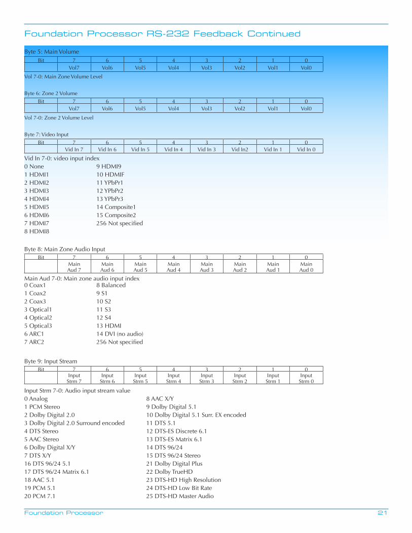
Byte 5: Main VolumeBit 7 6 5 4 3 2 1 0
Vol7 Vol6 Vol5 Vol4 Vol3 Vol2 Vol1 Vol0
Vol 7-0: Main Zone Volume Level
Byte 6: Zone 2 VolumeBit 7 6 5 4 3 2 1 0
Vol7 Vol6 Vol5 Vol4 Vol3 Vol2 Vol1 Vol0
Vol 7-0: Zone 2 Volume Level
Byte 7: Video InputBit 7 6 5 4 3 2 1 0
Vid In 7 Vid In 6 Vid In 5 Vid In 4 Vid In 3 Vid In2 Vid In 1 Vid In 0
Vid In 7-0: video input index0 None 9 HDMI91 HDMI1 10 HDMIF2 HDMI2 11 YPbPr13 HDMI3 12 YPbPr24 HDMI4 13 YPbPr35 HDMI5 14 Composite16 HDMI6 15 Composite27 HDMI7 256 Not specified8 HDMI8
Byte 8: Main Zone Audio InputBit 7 6 5 4 3 2 1 0
MainAud 7
MainAud 6
MainAud 5
MainAud 4
MainAud 3
MainAud 2
MainAud 1
MainAud 0
Main Aud 7-0: Main zone audio input index0 Coax1 8 Balanced1 Coax2 9 S12 Coax3 10 S23 Optical1 11 S34 Optical2 12 S45 Optical3 13 HDMI6 ARC1 14 DVI (no audio)7 ARC2 256 Not specified
Byte 9: Input StreamBit 7 6 5 4 3 2 1 0
InputStrm 7
InputStrm 6
InputStrm 5
InputStrm 4
InputStrm 3
InputStrm 2
InputStrm 1
InputStrm 0
Input Strm 7-0: Audio input stream value0 Analog 8 AAC X/Y1 PCM Stereo 9 Dolby Digital 5.12 Dolby Digital 2.0 10 Dolby Digital 5.1 Surr. EX encoded3 Dolby Digital 2.0 Surround encoded 11 DTS 5.14 DTS Stereo 12 DTS-ES Discrete 6.15 AAC Stereo 13 DTS-ES Matrix 6.16 Dolby Digital X/Y 14 DTS 96/247 DTS X/Y 15 DTS 96/24 Stereo16 DTS 96/24 5.1 21 Dolby Digital Plus17 DTS 96/24 Matrix 6.1 22 Dolby TrueHD18 AAC 5.1 23 DTS-HD High Resolution19 PCM 5.1 24 DTS-HD Low Bit Rate20 PCM 7.1 25 DTS-HD Master Audio
Foundation Processor RS-232 Feedback Continued
22Foundation Processor
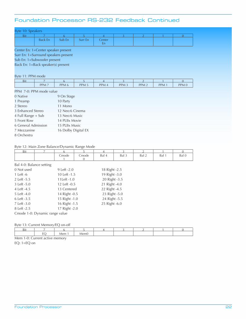
Byte 10: SpeakersBit 7 6 5 4 3 2 1 0
Back En Sub En Surr En CenterEn
Center En: 1=Center speaker presentSurr En: 1=Surround speakers presentSub En: 1=Subwoofer presentBack En: 1=Back speaker(s) present
Byte 11: PPM modeBit 7 6 5 4 3 2 1 0
PPM 7 PPM 6 PPM 5 PPM 4 PPM 3 PPM 2 PPM 1 PPM 0
PPM 7-0: PPM mode value0 Native 9 On Stage1 Preamp 10 Party2 Stereo 11 Mono3 Enhanced Stereo 12 Neo:6 Cinema4 Full Range + Sub 13 Neo:6 Music5 Front Row 14 PLIIx Movie6 General Admission 15 PLIIx Music7 Mezzanine 16 Dolby Digital EX8 Orchestra
Byte 12: Main Zone Balance/Dynamic Range ModeBit 7 6 5 4 3 2 1 0
Cmode1
Cmode0
Bal 4 Bal 3 Bal 2 Bal 1 Bal 0
Bal 4-0: Balance setting0 Not used 9 Left -2.0 18 Right -2.5 1 Left -6 10 Left -1.5 19 Right -3.0 2 Left -5.5 11Left -1.0 20 Right -3.5 3 Left -5.0 12 Left -0.5 21 Right -4.0 4 Left -4.5 13 Centered 22 Right -4.5 5 Left -4.0 14 Right -0.5 23 Right -5.0 6 Left -3.5 15 Right -1.0 24 Right -5.5 7 Left -3.0 16 Right -1.5 25 Right -6.0 8 Left -2.5 17 Right -2.0 Cmode 1-0: Dynamic range value
Byte 13: Current Memory/EQ on-offBit 7 6 5 4 3 2 1 0
EQ Mem 1 Mem0Mem 1-0: Current active memoryEQ: 1=EQ on
Foundation Processor RS-232 Feedback Continued
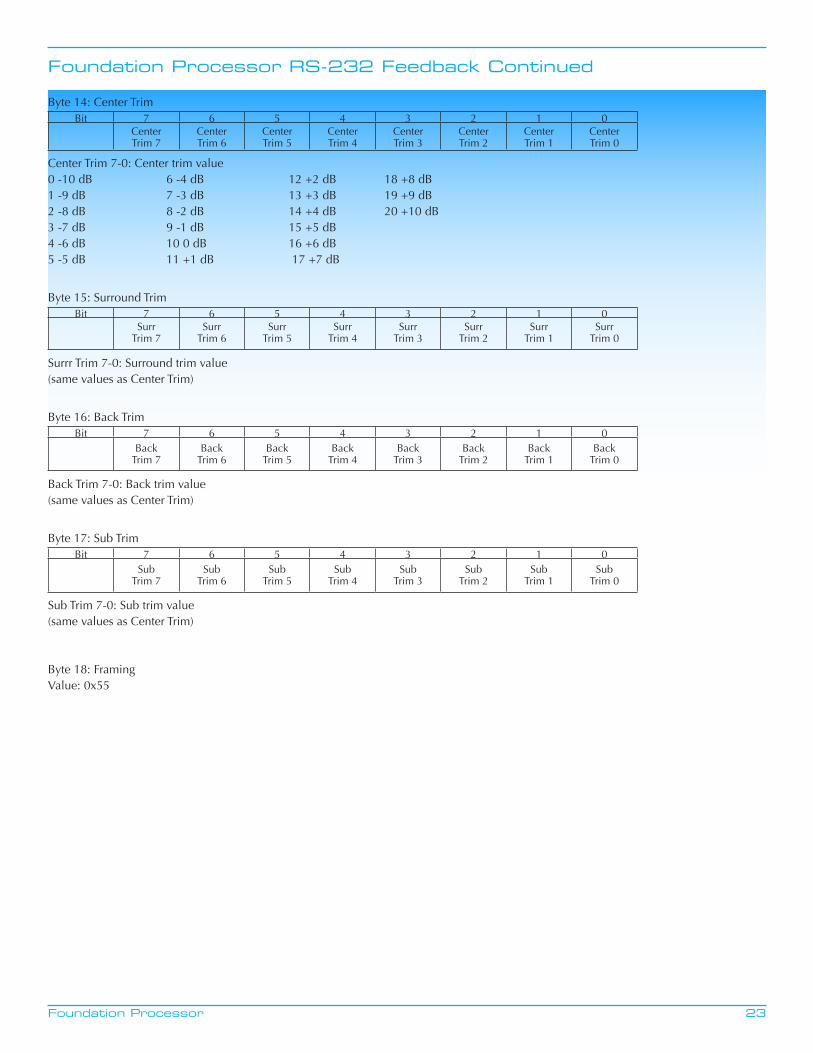
23Foundation Processor
Byte 14: Center TrimBit 7 6 5 4 3 2 1 0
CenterTrim 7
CenterTrim 6
CenterTrim 5
CenterTrim 4
CenterTrim 3
CenterTrim 2
CenterTrim 1
CenterTrim 0
Center Trim 7-0: Center trim value0 -10 dB 6 -4 dB 12 +2 dB 18 +8 dB 1 -9 dB 7 -3 dB 13 +3 dB 19 +9 dB 2 -8 dB 8 -2 dB 14 +4 dB 20 +10 dB 3 -7 dB 9 -1 dB 15 +5 dB 4 -6 dB 10 0 dB 16 +6 dB 5 -5 dB 11 +1 dB 17 +7 dB
Byte 15: Surround TrimBit 7 6 5 4 3 2 1 0
SurrTrim 7
SurrTrim 6
SurrTrim 5
SurrTrim 4
SurrTrim 3
SurrTrim 2
SurrTrim 1
SurrTrim 0
Surrr Trim 7-0: Surround trim value(same values as Center Trim)
Byte 16: Back TrimBit 7 6 5 4 3 2 1 0
BackTrim 7
BackTrim 6
BackTrim 5
BackTrim 4
BackTrim 3
BackTrim 2
BackTrim 1
BackTrim 0
Back Trim 7-0: Back trim value(same values as Center Trim)
Byte 17: Sub TrimBit 7 6 5 4 3 2 1 0
SubTrim 7
SubTrim 6
SubTrim 5
SubTrim 4
SubTrim 3
SubTrim 2
SubTrim 1
SubTrim 0
Sub Trim 7-0: Sub trim value(same values as Center Trim)
Byte 18: FramingValue: 0x55

24Foundation Processor
Warranty
This Krell product has a limited warranty of five years for parts and labor on circuitry from date of purchase or six years from date of original shipment from the Krell factory. Should this product fail to perform at any time during the warranty, Krell will repair it at no cost to the owner, except as set forth in this warranty.
The warranty does not apply to damage caused by acts of God or nature.
The warranty on this page shall be in lieu of any other warranty, expressed or implied, including, but not limited to, any implied warranty of merchantability or fitness for a particular purpose. There are no warranties which exceed beyond those described in this document. If this product does not perform as warranted herein, the owner’s sole remedy shall be repair. In no event will Krell be liable for incidental or consequential damages arising from purchase, use, or inability to use this product, even if Krell has been advised of the possibility of such damages.
Proof of purchase in the form of a bill of sale or receipted invoice substantiating that the unit is within the warranty period must be presented to obtain warranty service. The warranty begins on the date of retail purchase, as noted on the bill of sale or receipted invoice from an authorized Krell dealer or distributor.
The warranty for Krell products is valid only in the country to which they were originally shipped, through the authorized Krell distributor for that country, and at the factory. There may be restrictions on or changes to Krell’s warranty because of regulations within a specific country. Please check with your distributor for a complete understanding of the warranty in your country.
If a unit is serviced by a distributor who did not import the unit, there may be a charge for service, even if the product is within the warranty period.
Freight to the factory is your responsibility. Return freight within the United States (U.S.A.) is included in the warranty. If you have purchased your Krell product outside the U.S.A. and wish to have it serviced at the factory, all freight and associated charges to the factory are your responsibility.
Krell will pay return freight to the U.S.A.-based freight forwarder of your choice. Freight and other charges to ship the unit from the freight forwarder to you are also your responsibility.
Krell is not responsible for any damage incurred in transit. Krell will file claims for damages as necessary for units damaged in transit to the factory. You are responsible for filing claims for shipping damages during the return shipment.
Krell does not supply replacement parts and/or products to the owner of the unit. Replacement parts and/or products will be furnished only to the distributor performing service on this unit on an exchange basis only; any parts and/or products returned to Krell for exchange become the property of Krell.
No expressed or implied warranty is made for any Krell product damaged by accident, abuse, misuse, natural or personal disaster, or unauthorized modification.
Any unauthorized voltage conversion, disassembly, component replacement, perforation of chassis, updates, or modifica-tions performed to the unit will void the warranty.
The operating voltage of this unit is determined by the factory and can only be changed by an authorized Krell distributor or at the factory. The voltage for this product in the U.S.A. cannot be changed until six months from the original purchase date.
In the event that Krell receives a product for warranty service that has been modified in any way without Krell authorization, all warranties on that product will be void. The product will be returned to original factory layout specifications at the owner’s expense before it is repaired. All repairs required after the product has been returned to original factory specificationswill be charged to the customer, at current parts and labor rates.
All operational features, functions, and specifications and policies are subject to change

25Foundation Processor
Service
Return Authorization Procedure
If you believe there is a problem with your component, please contact your dealer, distributor, or the Krell factory to discuss the problem before you return the component for repair. To expedite service, you may wish to complete and e-mail the Service Request Form in the Service section of our website at: www.krellonline.com
To return a product to Krell, please follow this procedure so that we may serve you better:
1. Obtain a Return Authorization Number (R/A number) and shipping address from the Krell ServiceDepartment.
2. Insure and accept all liability for loss or damage to the product during shipment to the Krell factory andensure all freight (shipping) charges are prepaid.
3. The product may also be hand delivered if arrangements with the Service Department have been made inadvance. Proof of purchase will be required for warranty validation at the time of hand delivery.
NOTE: Use the original packaging to ensure the safe transit of the product to the factory, dealer, ordistributor. Krell may, at its discretion, return a product in new packaging and bill the owner for suchpackaging if the product received by Krell was boxed in nonstandard packaging or if the original packagingwas so damaged that it was unusable. If Krell determines that new packaging is required, the owner will benotified before the product is returned.
To purchase additional packaging, please contact your authorized Krell dealer, distributor, or the KrellService Department for assistance.
To Contact the Krell Service Department:
Telephone 203-799-9954 Monday-Friday, 9:00 am to 5:00 pm EST
Fax 203-799-9796
E-Mail [email protected]
World Wide Web http://www.krellonline.com
26Foundation Processor
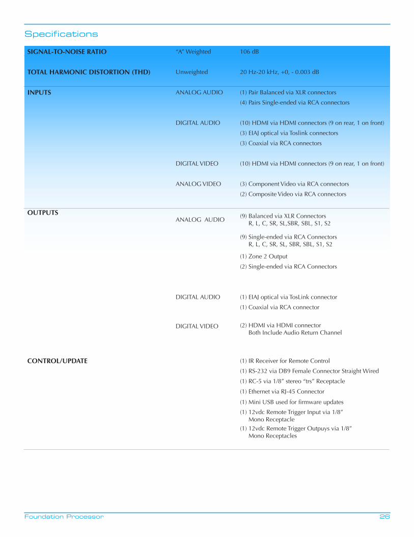
Specifications
SIGNAL-TO-NOISE RATIO “A” Weighted 106 dB
TOTAL HARMONIC DISTORTION (THD) Unweighted 20 Hz-20 kHz, +0, - 0.003 dB
INPUTS ANALOG AUDIO (1) Pair Balanced via XLR connectors
(4) Pairs Single-ended via RCA connectors
DIGITAL AUDIO (10) HDMI via HDMI connectors (9 on rear, 1 on front)
(3) EIAJ optical via Toslink connectors
(3) Coaxial via RCA connectors
DIGITAL VIDEO (10) HDMI via HDMI connectors (9 on rear, 1 on front)
ANALOG VIDEO (3) Component Video via RCA connectors
(2) Composite Video via RCA connectors
OUTPUTSANALOG AUDIO
(9) Balanced via XLR Connectors R, L, C, SR, SL,SBR, SBL, S1, S2
(9) Single-ended via RCA Connectors R, L, C, SR, SL, SBR, SBL, S1, S2
(1) Zone 2 Output
(2) Single-ended via RCA Connectors
DIGITAL AUDIO (1) EIAJ optical via TosLink connector
(1) Coaxial via RCA connector
DIGITAL VIDEO (2) HDMI via HDMI connector Both Include Audio Return Channel
CONTROL/UPDATE (1) IR Receiver for Remote Control
(1) RS-232 via DB9 Female Connector Straight Wired
(1) RC-5 via 1/8” stereo “trs” Receptacle
(1) Ethernet via RJ-45 Connector
(1) Mini USB used for firmware updates
(1) 12vdc Remote Trigger Input via 1/8” Mono Receptacle
(1) 12vdc Remote Trigger Outpuys via 1/8” Mono Receptacles
27Foundation Processor
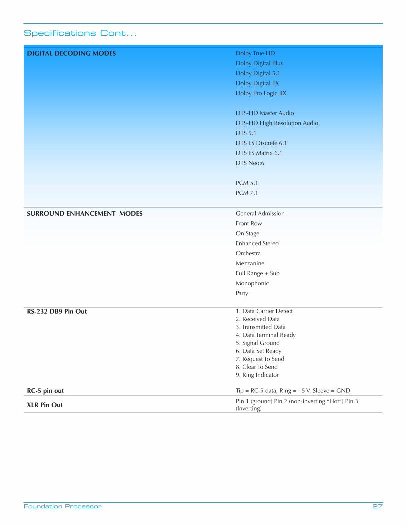
Specifications Cont...
DIGITAL DECODING MODES Dolby True HD
Dolby Digital Plus
Dolby Digital 5.1
Dolby Digital EX
Dolby Pro Logic IIX
DTS-HD Master Audio
DTS-HD High Resolution Audio
DTS 5.1
DTS ES Discrete 6.1
DTS ES Matrix 6.1
DTS Neo:6
PCM 5.1
PCM 7.1
SURROUND ENHANCEMENT MODES General Admission
Front Row
On Stage
Enhanced Stereo
Orchestra
Mezzanine
Full Range + Sub
Monophonic
Party
RS-232 DB9 Pin Out 1. Data Carrier Detect2. Received Data3. Transmitted Data4. Data Terminal Ready5. Signal Ground6. Data Set Ready7. Request To Send8. Clear To Send9. Ring Indicator
RC-5 pin out Tip = RC-5 data, Ring = +5 V, Sleeve = GND
XLR Pin Out Pin 1 (ground) Pin 2 (non-inverting “Hot”) Pin 3 (Inverting)
28Foundation Processor
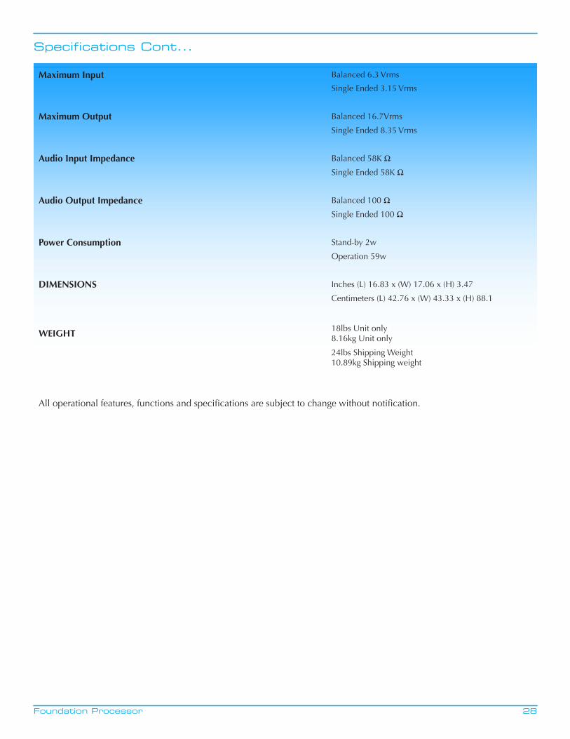
Specifications Cont...
Maximum Input Balanced 6.3 Vrms
Single Ended 3.15 Vrms
Maximum Output Balanced 16.7Vrms
Single Ended 8.35 Vrms
Audio Input Impedance Balanced 58K Ω
Single Ended 58K Ω
Audio Output Impedance Balanced 100 Ω
Single Ended 100 Ω
Power Consumption Stand-by 2w
Operation 59w
DIMENSIONS Inches (L) 16.83 x (W) 17.06 x (H) 3.47
Centimeters (L) 42.76 x (W) 43.33 x (H) 88.1
WEIGHT 18lbs Unit only8.16kg Unit only
24lbs Shipping Weight10.89kg Shipping weight
All operational features, functions and specifications are subject to change without notification.