railway foundation electronic, electrical and processor engineering
Post on 21-Dec-2015
224 views
TRANSCRIPT

Railway Foundation
Electronic, Electrical and Processor Engineering

2
Microprocessor Systems
• Four main components– Microprocessor– Memory– Inputs– Outputs
• Memory – ROM types – program and fixed data– RAM (Read & Write) – Data variables

3
Microprocessor
• Circuit is driven by a clock signal
• The microprocessor has internal registers.
• The action performed is determined by a set of binary instructions stored in ROM
• A reset starts the microprocessor at a predetermined point in the program (usually location 0)

4
Inputs & Outputs
• Normally Digital I/O ( two levels ‘0’ & ‘1’)• Normally parallel i.e grouped – 8bit PortsWhat about analogue signals?
– Analogue to Digital Converter (ADC)– Digital to Analogue Converter (DAC)
• Other devices include hardware timers and counters
• Digital data can also be in a serial format (e.g. RS232, RS 485 are serial standards)
5
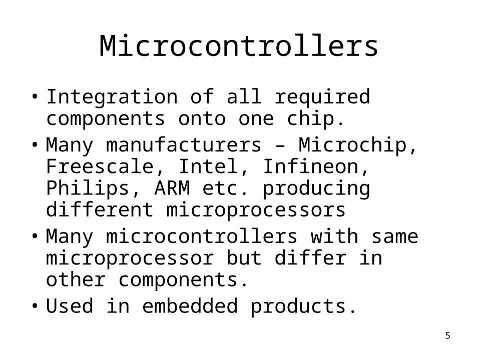
Microcontrollers
• Integration of all required components onto one chip.
• Many manufacturers – Microchip, Freescale, Intel, Infineon, Philips, ARM etc. producing different microprocessors
• Many microcontrollers with same microprocessor but differ in other components.
• Used in embedded products.

Examples
6
Rail - Points Heating Control Systems

7
Programming• Can be done at different levels
– Object (machine) binary code– Assembly language– High level language ( e.g. ‘C’ language)– Graphical (e.g. LabVIEW)
• Internal architecture • Memory Map• Programmers Model – different for
programming at different levels

8
EXAMPLES
Machine code –
0110111100001000 means move the value from W reg. to file register 00001000 i.e 8
Assembly –
Count EQU 8
MOVWF Count
A program called an assembler converts it to the binary object code.
An example machine instruction

9
00050 ;Constants 00051 LED equ 3 ;LED bit 3 on PORTB
00053 ;Reset vector 00054 ; This code will start executing when a reset occurs. 00055 000000 00056 ORG 0x0000 00057
00058 ;Start of main program000000 00059 Start:000000 9693 00060 bcf TRISB,LED ;Set PortB bit 3 as an o/p000002 9681 00061 bcf PORTB,LED ;set LED off000004 00062 Loop: ;while(1)000004 8681 00063 bsf PORTB,LED ; turn led on 000006 9681 00064 bcf PORTB,LED ; turn led off000008 D7FD 00065 bra Loop ;endwhile
CommentsBegin with ;Assembly
instructions
Program Line Numbers
Object code in HEX format
ROM location
Labels
An Assembler program

10
C Programming
• Portable • High level – Abstract• Standard constructs
– Variables – various data types– Selection ( if statements)– Loops (while, for, do)– Standard operations (+-*/)– Logical and bit-wise operations (AND OR
XOR etc.)

11
Simple ‘C’ outlineSelection - two typesif (comparison is true ){
Do this once;}
if (comparison is true){
do this;}else {
do that;}
Loops
while (comparison is true )
{
KEEP Doing this;
}
Comparisons:-
== is equal to
!= is not equal to
> is greater than
< is less than
>= is greater or equal to
<= is less than or equal to
Defining variables
unsigned char i; //8 bit value
int x; // 16 bit signed
unsigned int y; // 16 bit value
Misc.
// starts a comment
i++; // increment by one
i--; // decrement by one
&& // logical AND
|| // logical OR

Graphical Programming• LabVIEW is a graphical programming language that
uses icons instead of lines of text to create applications.• In contrast to text-based programming languages,
where instructions determine program execution, LabVIEW uses dataflow programming, where data determine execution.
12
13
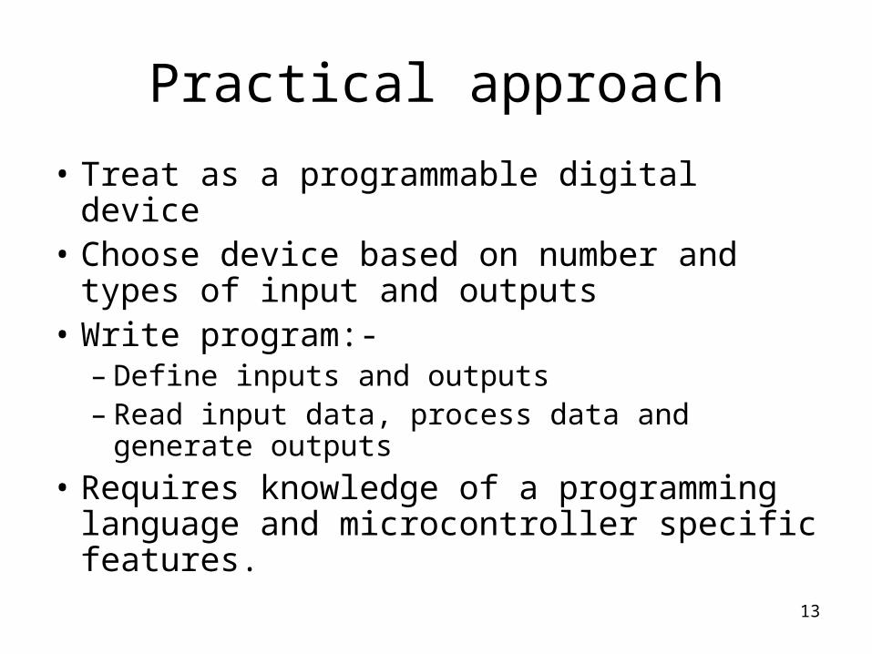
Practical approach
• Treat as a programmable digital device• Choose device based on number and types
of input and outputs• Write program:-
– Define inputs and outputs– Read input data, process data and generate
outputs
• Requires knowledge of a programming language and microcontroller specific features.

14
Analogue to Digital Converter
• n bits – determines the resolution
• Reference voltage sets the input range
• often have an analogue multiplexer to allow several input channels to use a single ADC
ADC
n bits
Analogue input voltage
Reference voltages (one is usually analogue ground)

15
Example 8 bit ADC
• Reference voltage of 0v and +5v• input voltage range = 5v - 0v = 5V• Number of digital values (steps) = 2n=28=256• Note! values range from 0 to 255• Resolution = Reference voltage range = 5
Number of digital values 256
=0.01953125 = 19.53125mV• This is the smallest change in voltage that can be
detected

160
255
4.98046875 Volts
Remember max digital value = 255.
Max convertible input = 255 × resolution in volts = 255 × 0.01953125
= 4.980468755
Input voltage

17
Digital Conversion
0
1
2
3
Digital value
Analogue input voltage
0.01953125
0.0390625
0.05859375