fort stewart · fort stewart was surveyed to identify the visual zones within the cantonment area....
TRANSCRIPT
Fort Stewart Installation Design Guide Executive Summary Page ES-1
INTRODUCTION
This document is the Executive Summary of the Fort Stewart Installation Design Guide (IDG or “Guide”). As a synopsis of the Guide it provides an overview of the existing conditions and command policies that relate to the design and management of facilities and grounds at Fort Stewart.
PURPOSE OF THE INSTALLATION DESIGN GUIDE
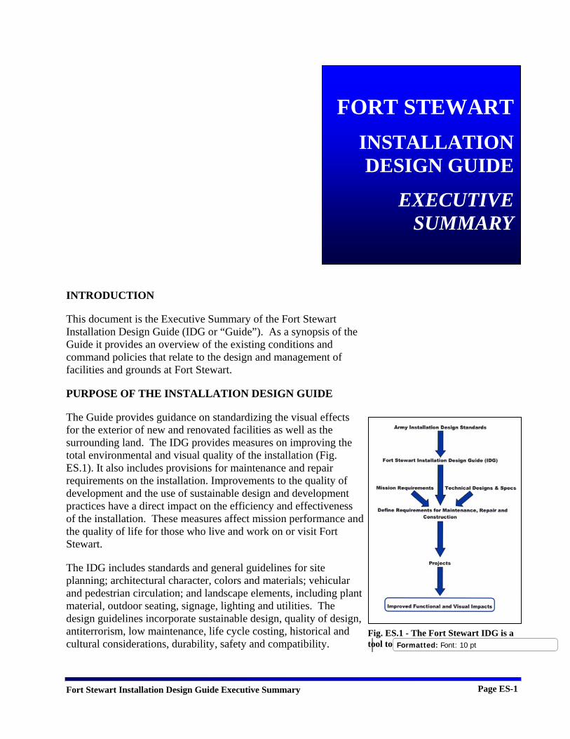
The Guide provides guidance on standardizing the visual effects for the exterior of new and renovated facilities as well as the surrounding land. The IDG provides measures on improving the total environmental and visual quality of the installation (Fig. ES.1). It also includes provisions for maintenance and repair requirements on the installation. Improvements to the quality of development and the use of sustainable design and development practices have a direct impact on the efficiency and effectiveness of the installation. These measures affect mission performance and the quality of life for those who live and work on or visit Fort Stewart.
The IDG includes standards and general guidelines for site planning; architectural character, colors and materials; vehicular and pedestrian circulation; and landscape elements, including plant material, outdoor seating, signage, lighting and utilities. The design guidelines incorporate sustainable design, quality of design, antiterrorism, low maintenance, life cycle costing, historical and cultural considerations, durability, safety and compatibility.
FORT STEWARTINSTALLATION DESIGN GUIDE
EXECUTIVE SUMMARY
Fig. ES.1 - The Fort Stewart IDG is a tool to implement Army standards. Formatted: Font: 10 pt

Fort Stewart Installation Design Guide Executive Summary Page ES-2
Stakeholders
This IDG is to be used by all individuals involved in the decision making process for design, construction, and maintenance of facilities (Fig. ES.2):
The primary stakeholders and users include the following: • Installation Commander and staff • Garrison Commander and staff • U.S. Army Corps of Engineers, Savannah District • Customers and other users of installation infrastructure • Consulting planners, architects, engineers, and landscape
architects (working on installation projects) • Maintenance personnel • Contractors employed by the Operations and Maintenance
Division
ARMY CORPS OF ENGINEERS
GARRISON COMMANDER
MAINTENANCE PERSONNEL
CONTRACTORS
CUSTOMERS
INSTALLATION COMMANDER AND STAFF
ARCHITECTS, LANDSCAPE
ARCHITECTS, ENGINEERS
IDG
Fig. ES.2 - A diagram of the Guide's primary stakeholders.

Fort Stewart Installation Design Guide Executive Summary Page ES-3
The ultimate success of the IDG depends on the commitment of all stakeholders to fully implement the guide, and on the proper education of installation staff about the existence and purpose of the Guide.
ORGANIZATION OF THE IDG
The IDG is organized to facilitate the preparation and execution of projects to improve the visual image of the installation and to ensure that design conforms to Army standards, including sustainability requirements.
• Section 2 “The Installation Design Guide Process and Implementation” describes how the IDG plays a part when initiating any maintenance, repair, renovation or new construction project and how to use the IDG as a resource.
• Section 3 “Design Guide Analysis Criteria” discusses specific goals and objectives promoted by the Fort Stewart IDG, the visual elements that are addressed by the IDG and the design principles employed in analyzing the current and desired state of the installation.
• Section 4 “Installation Profile” details the regional setting, natural environment and existing land use on Fort Stewart.
• Section 5, “Visual Themes and Zones” analyzes the design theme of Fort Stewart and breaks it down into a set of visual zones. Assets, liabilities and recommendations are described for each zone.
• Section 6 “Improvement Projects” provides a consolidated list of recommendations to correct the visual and functional liabilities identified for each visual zone. It also includes improvement projects developed by the installation to accomplish the recommendations.
• Section 7 “Site Planning Design Standards” discusses what factors and requirements must be considered in selecting and planning a building site.
• Section 8 “Buildings Design Standards” discusses what factors and requirements must be considered in building design.
• Section 9 “Circulation Design Standards” discusses what factors and requirements must be considered in the design of roads, parking lots and the pedestrian circulation system.
• Section 10 “Landscape Design Standards” discusses what factors and requirements must be considered in landscape design.
Fort Stewart Installation Design Guide Executive Summary Page ES-4
• Section 11 “Site Elements Design Standards” discusses what factors and requirements must be considered in the selection and location of site elements.
• Section 12 “Antiterrorism Design Standards” discusses what factors and requirements must be considered for all infrastructure that may affect antiterrorism efforts.
Responsibilities
As directed by the Secretary of the Army and the Chief of Staff, Army and approved by the Army Installation Management Board of Directors, the following responsibilities are established:
Assistant Chief of Staff for Installation Management (ACSIM): • Establish Army facility standards and approve deviations
from the standards. • Approve Army Installation Design Standards
Implementation Plan. • Approve Army Installation Design Standards Investment
Strategy.
Commander, Installation Management Command (IMCOM): • Develop and implement the Army Installation Design
Standards Implementation Plan. • Develop and implement the Army Installation Design
Standards Investment Strategy. • Ensure compliance with the Army Installation Design
Standards. • Maintain an electronic newsletter for communicating
changes in standards.
Installation Commander and Staff: • Chair Real Property Planning Board (RPPB) to review and
approve projects established by the Executive Steering Committee (ESC) and the Military Construction Army (MCA) Program.
Garrison Commander and Staff: • Maintain and provide IDG compliance for Fort Stewart. • Submit MCA project requests to the IMCOM Southeast
Region Office for approval and funding. After review and approval by the Garrison Commander, submit projects according to instructions provided by the IMCOM.
Fort Stewart Installation Design Guide Executive Summary Page ES-5
• Approve outcomes of Planning and Design Charrettes. See ACSIM memorandum, DAIM-ZA, “Planning Charettes for Military Construction, Army (MCA) Projects” dated 3 March 03. See also ACSIM Memorandum, DAIM-FD, “Conducting a Planning Charrette for Military Construction, Army (MCA) Projects” dated 2 Apr 03.
• The Directorate of Public Works (DPW) supports the Garrison Commander and Staff by performing the following tasks; o Developing the IDG. o Defining and communicating the responsibilities of
other organizations in implementing the IDG. o Ensuring that the processes needed for IDG
implementation have been established, implemented and maintained.
o Conducting Planning and Design Charrettes in accordance with the DIAM memoranda identified above.
U.S. Army Corps of Engineers, Savannah District: • Provide planning, design and construction support to Fort
Stewart.
Consulting Planners, Architects, Engineers and Landscape Architects:
• Use the IDG for planning and design to make Army standard designs conform to the Fort Stewart master plan for exterior appearance called “Southern Living Station of Choice.”
INSTALLATION PROFILE
The primary mission of Fort Stewart is to support and assist in the training of the 3rd ID. This mission is accomplished by providing the living, working, training and recreational facilities needed by approximately 16,000 active duty personnel, their dependents, civilian employees and retirees. Fort Stewart also supports tenant activities, predominantly the Army Reserve Component and National Guard units that train there.
Fort Stewart occupies portions of five counties in the coastal plain of southeast Georgia. The cantonment area is located about 40 miles southwest of Savannah near Hinesville, Georgia.
Fort Stewart is one of the largest Army installations in the United States, occupying a contiguous land area of 279,270 acres. Major

Fort Stewart Installation Design Guide Executive Summary Page ES-6
regional population centers include: Savannah and Jacksonville, Florida, 117 miles to the south. Figures ES.3 and ES.4 provide the geographical location and vicinity maps for Fort Stewart.
Fig.ES.3 - Fort Stewart Location Map
Fig. ES.4 - Fort Stewart Vicinity Map
Fort Stewart Installation Design Guide Executive Summary Page ES-7
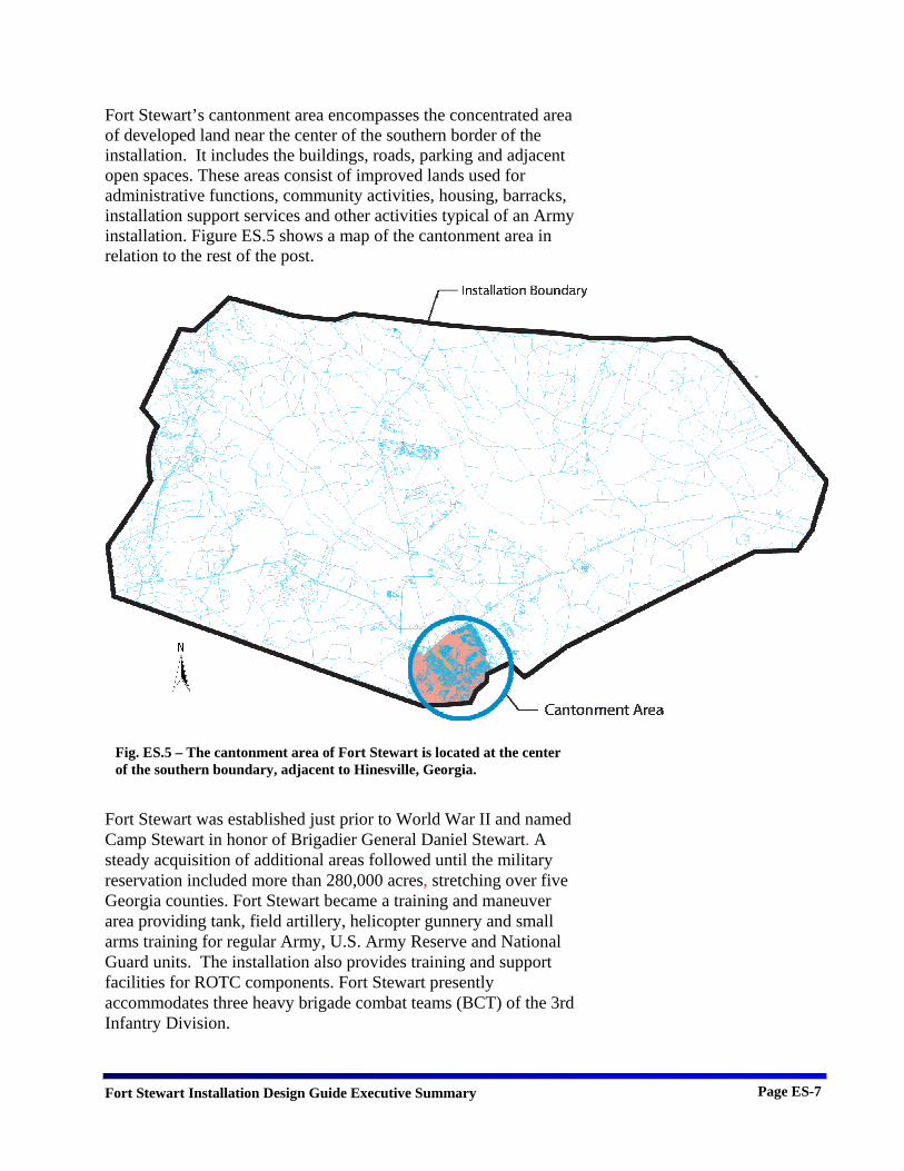
Fort Stewart’s cantonment area encompasses the concentrated area of developed land near the center of the southern border of the installation. It includes the buildings, roads, parking and adjacent open spaces. These areas consist of improved lands used for administrative functions, community activities, housing, barracks, installation support services and other activities typical of an Army installation. Figure ES.5 shows a map of the cantonment area in relation to the rest of the post.
Fort Stewart was established just prior to World War II and named Camp Stewart in honor of Brigadier General Daniel Stewart. A steady acquisition of additional areas followed until the military reservation included more than 280,000 acres, stretching over five Georgia counties. Fort Stewart became a training and maneuver area providing tank, field artillery, helicopter gunnery and small arms training for regular Army, U.S. Army Reserve and National Guard units. The installation also provides training and support facilities for ROTC components. Fort Stewart presently accommodates three heavy brigade combat teams (BCT) of the 3rd Infantry Division.
Fig. ES.5 – The cantonment area of Fort Stewart is located at the center of the southern boundary, adjacent to Hinesville, Georgia.
Fort Stewart Installation Design Guide Executive Summary Page ES-8
Fort Stewart is designated as a Class 1 Army Installation, requiring new development to phase out obsolete and temporary buildings. A very active construction program is underway at Fort Stewart to accommodate the current Army mission requirements for new facilities.
Topographic relief is very limited on Fort Stewart. The topography is typical of the physical features in the Atlantic Coastal Plain physiographic province. The installation is relatively level with five terraces gently rising east to west from four to 186 feet above sea level. Most of the land is less than 33 feet above sea level with slopes less than three percent. Relatively small changes in elevation have significant effects on vegetation with wetlands and hardwood bottoms in lower areas and upland pines and scattered hardwoods at slightly higher elevations.
The subtropical climate of the region is pleasant, as evidenced by the many visitors to the region’s resort communities, such as Hilton Head. The winters are short and mild, with long spring and fall seasons, while summers are hot and humid. The abundance of both sunshine and rainfall creates a favorable natural environment.
INSTALLATION DESIGN GOALS AND OBJECTIVES
The goal of the Fort Stewart IDG is to provide guidance and to establish requirements for all installation personnel involved in design, construction, maintenance or renovation and to develop, implement and sustain Fort Stewart infrastructure in order to meet current and future mission needs.
The objectives of the IDG are: • To provide design standards that define color, materials,
style, proportion, signage and other aspects of design for all visual elements.
• To provide instructions for implementation of the design guidelines and selection of materials for new construction, renovation, maintenance and repair projects, as appropriate.
• To provide direction for accomplishing sustainable development.
• To provide guidance to integrate antiterrorism standards.
VISUAL SURVEY AND ANALYSIS
Fort Stewart was surveyed to identify the visual zones within the cantonment area. Seven visual zones were defined based on their visual features, architectural trends and the functions of the

Fort Stewart Installation Design Guide Executive Summary Page ES-9
predominant facilities. Southern Living Station of Choice is the architectural theme used for the design and construction of facilities in these visual zones. The identified visual zones are shown in Figure ES.6.
The following pages describe the seven visual zones and contain photographs of the primary visual character of each.
Headquarters Visual Zone The Headquarters Visual Zone is the command and administrative center of Fort Stewart and includes the Main Gate, the 3rd Infantry Division (Mech) headquarters building, the Education Center, the Museum, the Legal Center and Marne Gardens.
The Headquarters Visual Zone, in its architecture and site planning, represents the traditional core of Fort Stewart and is dominated by buildings designed with the Southern Living Station of Choice architectural theme. The consistent architectural theme produces a visually cohesive campus.
The orderly arrangement of buildings relates well to the original chevron-shaped street plan for Fort Stewart. The original planning incorporated the parade grounds, axial relationships between features, controlled vistas and a symmetrical arrangement of roadways to create a complex with a cohesive campus feeling.
The Command and Control Center is strategically located at the apex of the chevron plan and is visually prominent when viewed from the Main Gate (Fig. ES.7). Subordinate structures are arranged around the Command and Control Center. Marne Garden, adjacent to the Command and Control Center, provides a setting for military ceremonies and other events for visiting dignitaries (ES.8). In addition to a reviewing stand, the garden contains formal landscaping and an orderly arrangement of sculptural monuments related to the history of the 3rd ID.
The Soldier Service Center, the Military Police Battalion Headquarters, the Chapel and the Education Center, recent examples of Southern Living Station of Choice architectural theme, are located within the Headquarters Visual Zone (Fig. ES.9). The Education Center is located just outside of the Main Gate to allow for convenient public access
The exterior display at the museum impressively communicates the past and current missions of Fort Stewart. A number of structures, landmarks and monuments representing the history of the installation are located throughout the visual zone.
Fig. ES.8 – View of the reviewing stand at Marne Garden.
Fig. ES.7 – View of the Command and Control Center from the Main Gate.
Fig. ES.9 – The Soldier Service Center incorporates key elements of the Southern Living Station of Choice architectural theme.

Fort Stewart Installation Design Guide Executive Summary Page ES-10
Stands of mature trees are plentiful and provide dramatic park-like views inside the Main Gate and provide an attractive background for static displays and buildings within the visual zone (Fig. ES.10). This combination of buildings, lawns, static displays and stands of trees produces dramatic views and projects a clear sense of order and formality.
Town Center Visual Zone The Town Center Visual Zone is centrally located in the cantonment area and is the primary focal point for community services and retail activities on Fort Stewart. This visual zone also serves as a transitional area between the Headquarters Visual Zone and the other visual zones. The Town Center Visual Zone contains three sub-areas; the retail center, the hospital and the recreation facilities. The Southern Living Station of Choice architectural theme is clearly dominant in this visual zone.
The high concentration of community functions located within the Town Center Visual Zone produces a feeling of vibrancy and a sense of community (ES.11).
Most buildings have facades and architectural details that communicate their functions as retail and community service outlets. Many buildings have entrance arcades and canopies that provide protection from the sun and rain and produce an appealing sense of scale. Overhangs, signage and architectural detailing articulate building entries and produce visual interest. There is a general consistency in overall appearance of buildings that share a common construction era. The predominant building material is brick ranging from light to medium brown (ES.12).
Walkways connecting adjacent buildings and activity areas provide pedestrian access and reduce vehicular traffic (Fig. ES.13). Substantial areas of mature landscaping are located at key locations such as near building entrances and in parking lots. Seating, lighting and other elements near building entrances provide convenience and safety and make them appear inviting. The hospital site is an example of the effective use of massive planting to subdue the apparent size and to control views of a very large building with extensive parking lots.
Barracks Visual Zone The Barracks Visual Zone contains an interrelated system of soldier quarters, operations buildings, dining facilities, classrooms, community and retail services and recreation facilities.
Fig. ES.10 – Stands of pine trees bound open space throughout the Headquarters Visual Zone.
Fig. ES.11 – The entrance to the PX is an attractive and active area.
Fig. ES.13 – Pedestrian walks connect many parts of the Town Center Visual Zone.
Fig. ES.12 – Most buildings are clad with light to medium colored brick.

Fort Stewart Installation Design Guide Executive Summary Page ES-11
Barracks, operations and support facilities are efficiently integrated, with appropriate relationships to each other and to adjoining industrial and green space land uses.
The architectural style and color of the exterior building materials makes this visual zone easily recognizable. The use of consistent colors and forms presents an orderly image (Fig. ES.14). The spaces between the barracks buildings have a variety of site furnishings and other elements that give the complexes a pleasing human scale. The northern portion of this visual zone has a comfortable and pleasing environment due to the preservation of native pine trees.
Open space is available close to the barracks for recreation and company level training (Fig. ES.15). Streets and parking lots interconnect to simplify vehicle circulation and reduce conflicts between parking lot traffic and street traffic. Pedestrian access is encouraged and accommodated in a large portion of this visual zone by centrally located walkways (Fig. ES.16).
Installation Support Visual Zone The Installation Support Visual Zone is comprised of Tactical Equipment Maintenance Facilities (TEMF), storage facilities, the utility systems and the power plant (Fig. ES.17). It also includes cantonment area expansion along the western end of 15th Street.
Architecturally, the zone consists of large-scale industrial buildings most of which have metal panel and concrete block exteriors and clerestory glass inserts. The utilitarian appearance of most of the buildings clearly communicates the industrial nature of the zone. The light colors of most of the buildings visually unify the installation support areas and allow small areas of brighter colors to stand out as accents.
Large expanses between these facilities are paved for storage and maintenance of vehicles, outdoor materials storage and open work areas. This visual zone is located in a well-defined land use area separate from housing, administration and community facilities.
The orderly appearance of parked military vehicles and materiel storage creates an appropriate military image. Circulation within the large compounds allows for minimum use of roadways for support vehicles. Trees and shrubs are sometimes combined with fencing to visually screen hardstand, outdoor storage and industrial buildings. Many installation support areas have area lighting to accommodate nighttime work and to increase security. Most
Fig. ES.15 – Open space adjoining barracks is used for training and recreation.
Fig. ES.14 – Most barracks and unit operations buildings are of similar architectural style and materials.
Fig. ES.17 – The TEMF are typical buildings in this visual zone.
Fig. ES.16 – Walkways connect parking to barracks and adjacent barracks complexes to each other.
Fort Stewart Installation Design Guide Executive Summary Page ES-12
industrial facilities are sited away from roadways and inside fenced compounds.
National Guard Visual Zone
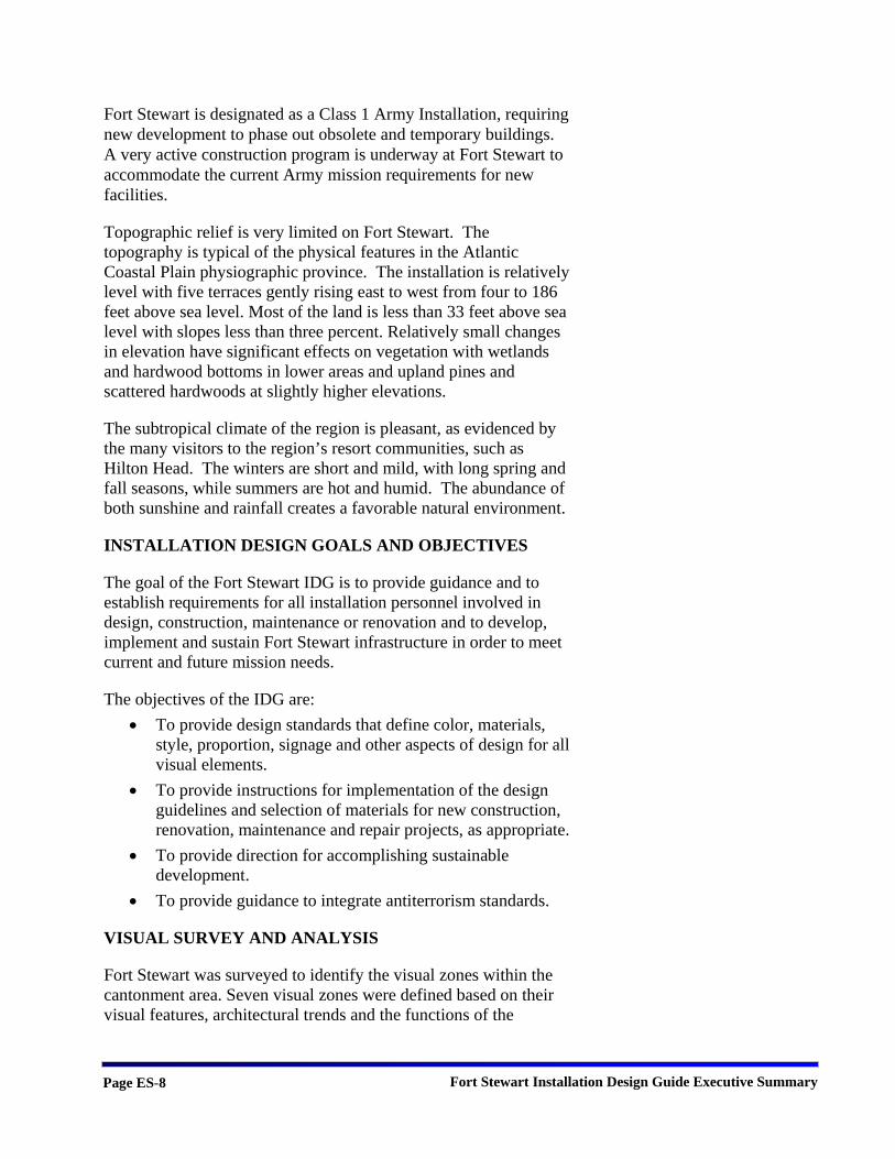
The eastern portion of the cantonment area contains the distinct troop housing facilities of the National Guard Visual Zone. This area is treated separately due to the periodic, short-term use of its unique, permanent facilities. The single-story, concrete masonry barracks are uniform in appearance and function, with repetitive architecture and site improvements (Fig. ES.18). They are intensively used during short, infrequent time periods. This pattern creates unique needs and requirements for the facilities including a simple circulation system, identifiable unit areas and provisions for setting up temporary equipment.
Housing Visual Zone
The Housing Visual Zone contains numerous neighborhoods north of the cantonment area. Visual perceptions of the district are generally positive because of the variety of housing types, styles and densities. Schools, parks and other neighborhood facilities are located among heavily wooded open space, adding to the positive perception. The variety of neighborhoods with different densities and site layouts enhances the interest of the visual zone and provides a sense of identity within the Fort Stewart community.
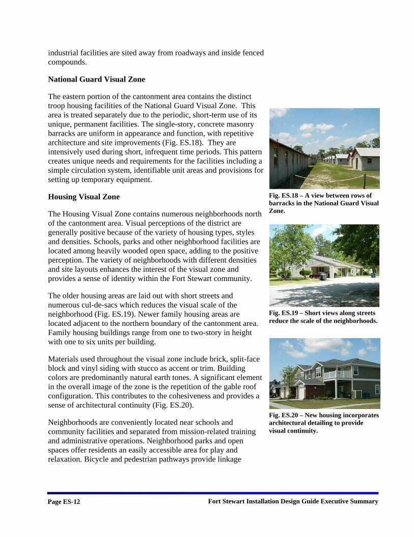
The older housing areas are laid out with short streets and numerous cul-de-sacs which reduces the visual scale of the neighborhood (Fig. ES.19). Newer family housing areas are located adjacent to the northern boundary of the cantonment area. Family housing buildings range from one to two-story in height with one to six units per building.
Materials used throughout the visual zone include brick, split-face block and vinyl siding with stucco as accent or trim. Building colors are predominantly natural earth tones. A significant element in the overall image of the zone is the repetition of the gable roof configuration. This contributes to the cohesiveness and provides a sense of architectural continuity (Fig. ES.20).
Neighborhoods are conveniently located near schools and community facilities and separated from mission-related training and administrative operations. Neighborhood parks and open spaces offer residents an easily accessible area for play and relaxation. Bicycle and pedestrian pathways provide linkage
Fig. ES.20 – New housing incorporates architectural detailing to provide visual continuity.
Fig. ES.19 – Short views along streets reduce the scale of the neighborhoods.
Fig. ES.18 – A view between rows of barracks in the National Guard Visual Zone.
Fort Stewart Installation Design Guide Executive Summary Page ES-13
between housing areas and offer a safe alternative to roadways for walking or jogging (ES.21).
Native vegetation retained in the Housing Visual Zone provides a natural, low maintenance amenity. Large stands of pine trees help to define neighborhoods and create a feeling of permanence. Where street signs, mailboxes, bus shelters and landscaping are well-maintained they contribute to a sense of order and pride.
Green Space Visual Zone
Recreation facilities, buffer areas, ranges, undeveloped native pine forests, training areas and wetlands comprise the Green Space Visual Zone at Fort Stewart. While geographically much larger than the other visual zones, only small portions of it are commonly visible to the general installation population.
There are several important green spaces within the cantonment area. These spaces significantly influence the visual character of the installation. Expansion of the cantonment area will necessarily involve conversion of portions of the Green Space Visual Zone to other visual zones because the existing cantonment area is fully developed.
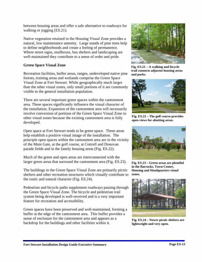
Open space at Fort Stewart tends to be green space. These areas help establish a positive visual image of the installation. The principle open spaces within the cantonment area are in the vicinity of the Main Gate, at the golf course, at Cottrell and Donovan parade fields and in the family housing areas (Fig. ES.22).
Much of the green and open areas are interconnected with the larger green areas that surround the cantonment area (Fig. ES.23).
The buildings in the Green Space Visual Zone are primarily picnic shelters and other recreation structures which visually contribute to the rustic and natural character (Fig. ES.24).
Pedestrian and bicycle paths supplement roadways passing through the Green Space Visual Zone. The bicycle and pedestrian trail system being developed is well-received and is a very important feature for recreation and accessibility.
Green spaces have been preserved and well-maintained, forming a buffer at the edge of the cantonment area. This buffer provides a sense of enclosure for the cantonment area and appears as a backdrop for the buildings and other facilities within it.
Fig. ES.22 – The golf course provides open views for abutting areas.
Fig. ES.23 – Green areas are plentiful in the Barracks, Town Center, Housing and Headquarters visual zones.
Fig. ES.24 – Newer picnic shelters are lightweight and very open.
Fig. ES.21 – A walking and bicycle trail connects adjacent housing areas and parks.
Fort Stewart Installation Design Guide Executive Summary Page ES-14
Warrior’s Walk, located at Cotrell Parade Field, is a dramatic and moving memorial to the soldiers of the 3rd ID who have been lost in Afghanistan and Iraq (Fig. ES.25).
INSTALLATION DESIGN GUIDE STANDARDS
Site Planning Design Standards
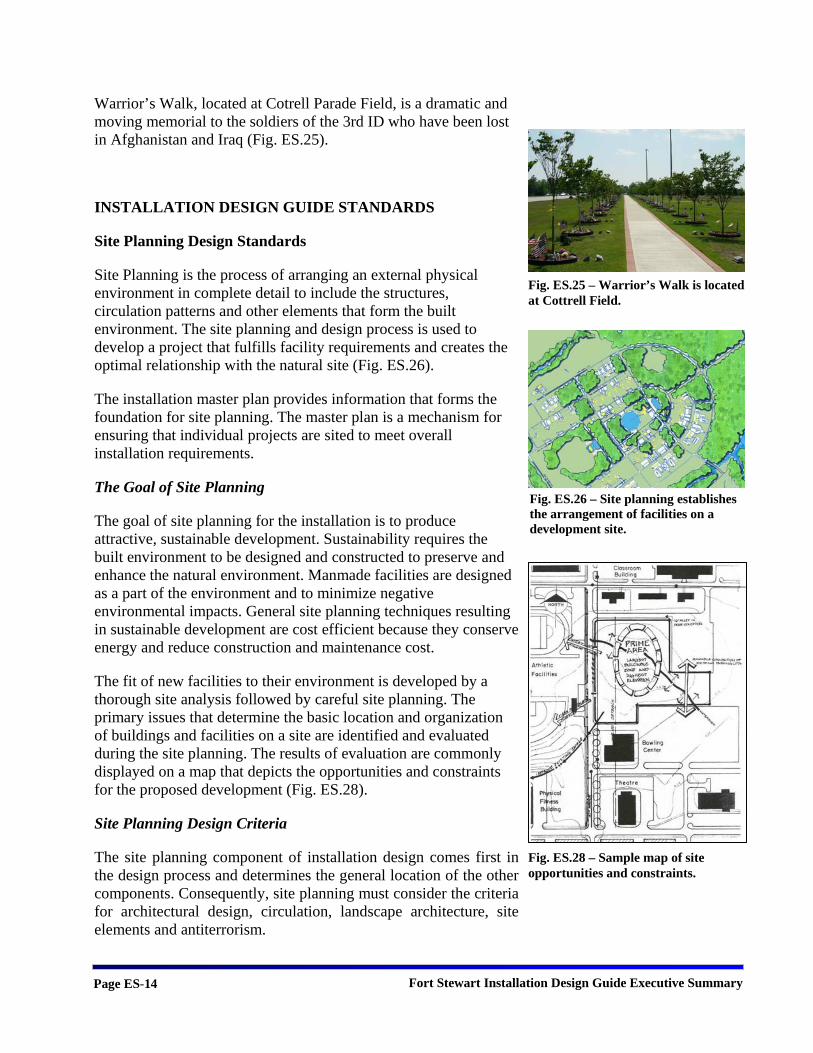
Site Planning is the process of arranging an external physical environment in complete detail to include the structures, circulation patterns and other elements that form the built environment. The site planning and design process is used to develop a project that fulfills facility requirements and creates the optimal relationship with the natural site (Fig. ES.26).
The installation master plan provides information that forms the foundation for site planning. The master plan is a mechanism for ensuring that individual projects are sited to meet overall installation requirements.
The Goal of Site Planning
The goal of site planning for the installation is to produce attractive, sustainable development. Sustainability requires the built environment to be designed and constructed to preserve and enhance the natural environment. Manmade facilities are designed as a part of the environment and to minimize negative environmental impacts. General site planning techniques resulting in sustainable development are cost efficient because they conserve energy and reduce construction and maintenance cost.
The fit of new facilities to their environment is developed by a thorough site analysis followed by careful site planning. The primary issues that determine the basic location and organization of buildings and facilities on a site are identified and evaluated during the site planning. The results of evaluation are commonly displayed on a map that depicts the opportunities and constraints for the proposed development (Fig. ES.28).
Site Planning Design Criteria
The site planning component of installation design comes first in the design process and determines the general location of the other components. Consequently, site planning must consider the criteria for architectural design, circulation, landscape architecture, site elements and antiterrorism.
Fig. ES.25 – Warrior’s Walk is located at Cottrell Field.
Fig. ES.28 – Sample map of site opportunities and constraints.
Fig. ES.26 – Site planning establishes the arrangement of facilities on a development site.
Fort Stewart Installation Design Guide Executive Summary Page ES-15
The natural terrain is a major determinant of the layout and form of the installation. Site planning should insure that the natural topography of the site is maintained. Natural drainage corridors, floodplains and waterways should be preserved during the site planning process. New and redeveloped facilities must be designed in response to local climatic conditions to provide a more comfortable environment and reduce the demands for heating and cooling.
New development will be designed to preserve and enhance scenic and other attractive views and vistas and to screen unattractive views and vistas. Visual extensions through open spaces will be incorporated as much as practicable to provide a sense of orientation, relief and enjoyment.
New development and additions will be designed to protect and preserve existing native vegetation. This preservation reduces maintenance and enhances sustainability.
The site plan provides the locations of the manmade development that will occur on site. It establishes the spatial relationships as well as the relationships between manmade and existing natural features.
Building Design Standards
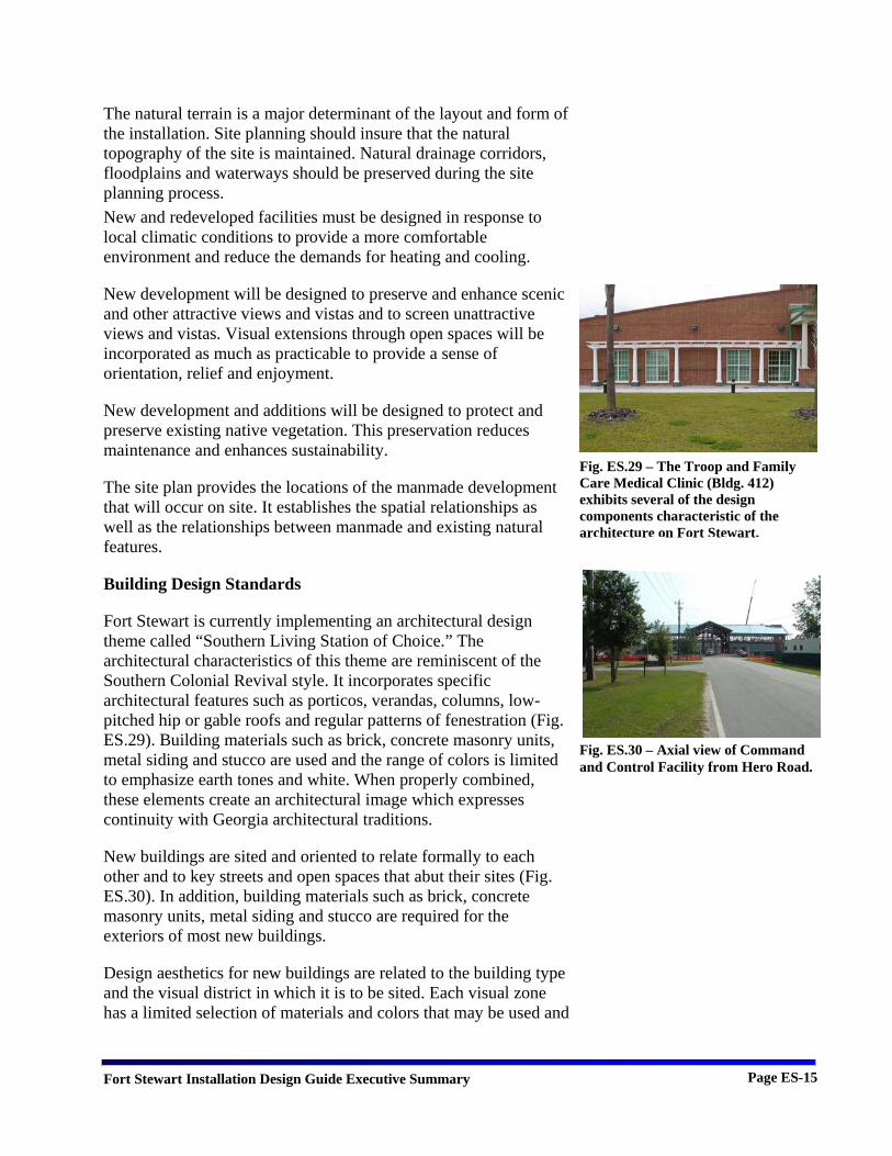
Fort Stewart is currently implementing an architectural design theme called “Southern Living Station of Choice.” The architectural characteristics of this theme are reminiscent of the Southern Colonial Revival style. It incorporates specific architectural features such as porticos, verandas, columns, low-pitched hip or gable roofs and regular patterns of fenestration (Fig. ES.29). Building materials such as brick, concrete masonry units, metal siding and stucco are used and the range of colors is limited to emphasize earth tones and white. When properly combined, these elements create an architectural image which expresses continuity with Georgia architectural traditions.
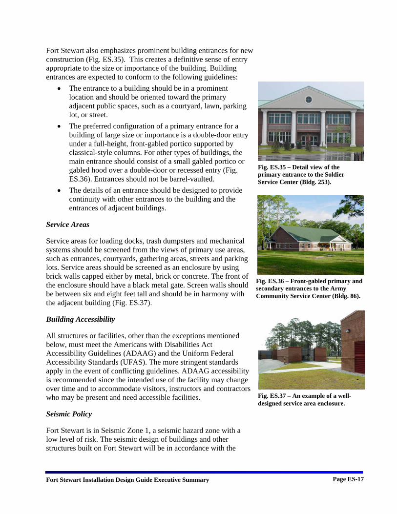
New buildings are sited and oriented to relate formally to each other and to key streets and open spaces that abut their sites (Fig. ES.30). In addition, building materials such as brick, concrete masonry units, metal siding and stucco are required for the exteriors of most new buildings.
Design aesthetics for new buildings are related to the building type and the visual district in which it is to be sited. Each visual zone has a limited selection of materials and colors that may be used and
Fig. ES.29 – The Troop and Family Care Medical Clinic (Bldg. 412) exhibits several of the design components characteristic of the architecture on Fort Stewart.
Fig. ES.30 – Axial view of Command and Control Facility from Hero Road.

Fort Stewart Installation Design Guide Executive Summary Page ES-16
it is generally expected that architectural features will be used to create a feeling of human scale (Fig. ES.31).
Sustainable Design- Fort Stewart requires the practice of sustainable design in the development of new facilities. Sustainable design reduces construction and maintenance costs and conserves energy through proper construction and materials selection.
Building Design Objectives-Building design objectives incorporate architectural design elements compatible with the Southern Living Station of Choice theme. Additional objectives include:
• Accommodate natural site conditions; • Use sustainable construction materials and practices; • Design facades with regular patterns of fenestration; • Adapt buildings to natural site conditions (Fig. ES.32); • Preserve land by reusing former building sites when
possible; and • Maximize architectural compatibility between new and
existing facilities (Fig. ES 33).
Architectural Character Fort Stewart has had three major building periods in its history and is currently in its fourth. As a result, architectural styles and materials vary but are compatible throughout the cantonment area.
A number of buildings have been constructed in the current period and more are planned. These include the Command and Control Facility (Bldg. 001), the Army Education Center, the Soldier Service Center (Bldg. 253), the Troop and Family Care Medical Clinic (Bldg. 412), the Military Police Battalion Headquarters (Bldg. 258), the Post Chapel (Bldg. 500), the entrance gates and the new BCT area. They are brick with metal low-pitched hip or gable roofs and feature simple, classical-style columns (Fig. ES.34).
Fort Stewart seeks to further achieve consistency in design throughout the visual zones by applying the design preferences of the Southern Living Station of Choice theme. Development of consistent character provides a coherent ‘sense of order’ and ‘sense of place.’ This relationship of design comes from using compatible scale, massing, form, color, texture, materials and fenestration.
Fig. ES.31 – A combination of materials and a varying roofline emphasize the human scale of the barracks.
Fig. ES.34 – The Army Education Center.
Fig. ES.32 – The Family Readiness Center (Bldg. 87) was sited around existing pine trees.
Fig. ES.33 – The Officer/SNCO quarters fit well into the National Guard Visual Zone (Bldgs. 13305 and 13304).
Fort Stewart Installation Design Guide Executive Summary Page ES-17
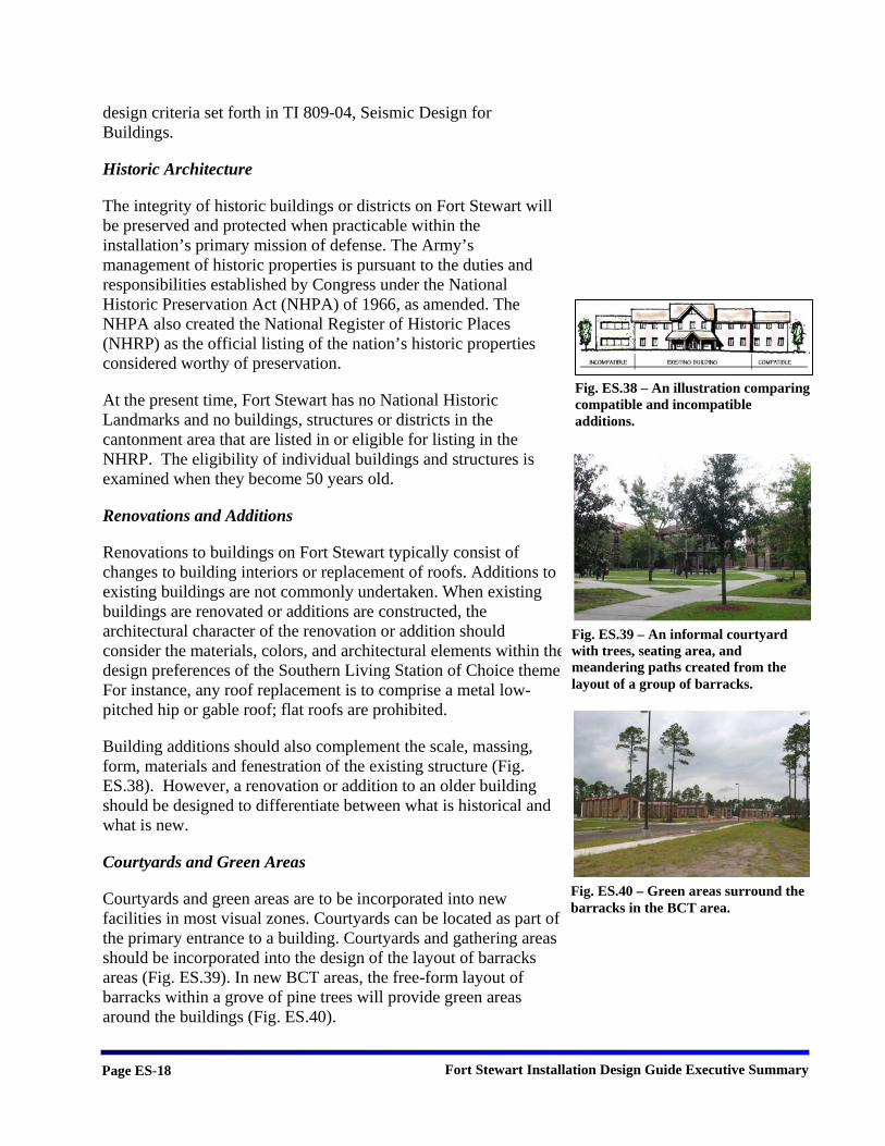
Fort Stewart also emphasizes prominent building entrances for new construction (Fig. ES.35). This creates a definitive sense of entry appropriate to the size or importance of the building. Building entrances are expected to conform to the following guidelines:
• The entrance to a building should be in a prominent location and should be oriented toward the primary adjacent public spaces, such as a courtyard, lawn, parking lot, or street.
• The preferred configuration of a primary entrance for a building of large size or importance is a double-door entry under a full-height, front-gabled portico supported by classical-style columns. For other types of buildings, the main entrance should consist of a small gabled portico or gabled hood over a double-door or recessed entry (Fig. ES.36). Entrances should not be barrel-vaulted.
• The details of an entrance should be designed to provide continuity with other entrances to the building and the entrances of adjacent buildings.
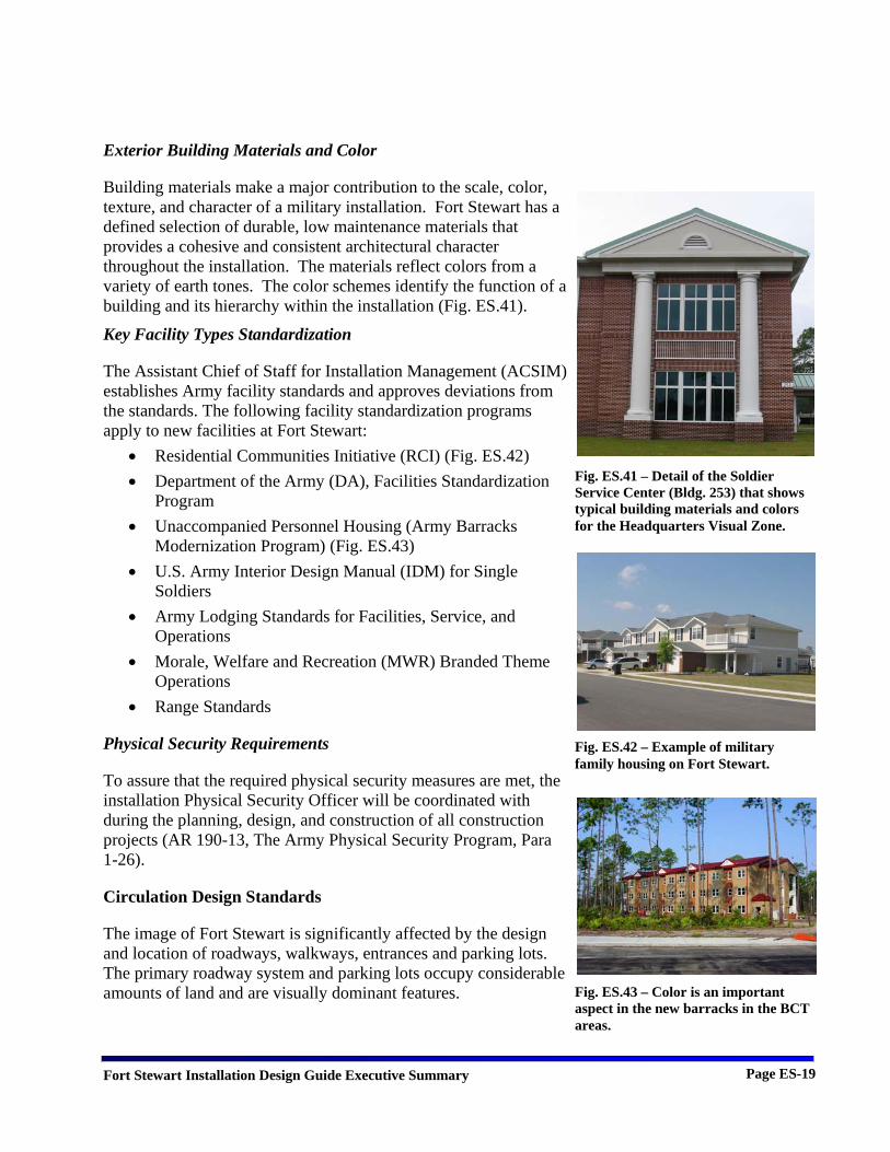
Service Areas
Service areas for loading docks, trash dumpsters and mechanical systems should be screened from the views of primary use areas, such as entrances, courtyards, gathering areas, streets and parking lots. Service areas should be screened as an enclosure by using brick walls capped either by metal, brick or concrete. The front of the enclosure should have a black metal gate. Screen walls should be between six and eight feet tall and should be in harmony with the adjacent building (Fig. ES.37).
Building Accessibility
All structures or facilities, other than the exceptions mentioned below, must meet the Americans with Disabilities Act Accessibility Guidelines (ADAAG) and the Uniform Federal Accessibility Standards (UFAS). The more stringent standards apply in the event of conflicting guidelines. ADAAG accessibility is recommended since the intended use of the facility may change over time and to accommodate visitors, instructors and contractors who may be present and need accessible facilities.
Seismic Policy
Fort Stewart is in Seismic Zone 1, a seismic hazard zone with a low level of risk. The seismic design of buildings and other structures built on Fort Stewart will be in accordance with the
Fig. ES.35 – Detail view of the primary entrance to the Soldier Service Center (Bldg. 253).
Fig. ES.37 – An example of a well-designed service area enclosure.
Fig. ES.36 – Front-gabled primary and secondary entrances to the Army Community Service Center (Bldg. 86).
Fort Stewart Installation Design Guide Executive Summary Page ES-18
design criteria set forth in TI 809-04, Seismic Design for Buildings.
Historic Architecture
The integrity of historic buildings or districts on Fort Stewart will be preserved and protected when practicable within the installation’s primary mission of defense. The Army’s management of historic properties is pursuant to the duties and responsibilities established by Congress under the National Historic Preservation Act (NHPA) of 1966, as amended. The NHPA also created the National Register of Historic Places (NHRP) as the official listing of the nation’s historic properties considered worthy of preservation.
At the present time, Fort Stewart has no National Historic Landmarks and no buildings, structures or districts in the cantonment area that are listed in or eligible for listing in the NHRP. The eligibility of individual buildings and structures is examined when they become 50 years old.
Renovations and Additions
Renovations to buildings on Fort Stewart typically consist of changes to building interiors or replacement of roofs. Additions to existing buildings are not commonly undertaken. When existing buildings are renovated or additions are constructed, the architectural character of the renovation or addition should consider the materials, colors, and architectural elements within the design preferences of the Southern Living Station of Choice theme. For instance, any roof replacement is to comprise a metal low-pitched hip or gable roof; flat roofs are prohibited.
Building additions should also complement the scale, massing, form, materials and fenestration of the existing structure (Fig. ES.38). However, a renovation or addition to an older building should be designed to differentiate between what is historical and what is new.
Courtyards and Green Areas
Courtyards and green areas are to be incorporated into new facilities in most visual zones. Courtyards can be located as part of the primary entrance to a building. Courtyards and gathering areas should be incorporated into the design of the layout of barracks areas (Fig. ES.39). In new BCT areas, the free-form layout of barracks within a grove of pine trees will provide green areas around the buildings (Fig. ES.40).
Fig. ES.38 – An illustration comparing compatible and incompatible additions.
Fig. ES.39 – An informal courtyard with trees, seating area, and meandering paths created from the layout of a group of barracks.
Fig. ES.40 – Green areas surround the barracks in the BCT area.
Fort Stewart Installation Design Guide Executive Summary Page ES-19
Exterior Building Materials and Color
Building materials make a major contribution to the scale, color, texture, and character of a military installation. Fort Stewart has a defined selection of durable, low maintenance materials that provides a cohesive and consistent architectural character throughout the installation. The materials reflect colors from a variety of earth tones. The color schemes identify the function of a building and its hierarchy within the installation (Fig. ES.41).
Key Facility Types Standardization
The Assistant Chief of Staff for Installation Management (ACSIM) establishes Army facility standards and approves deviations from the standards. The following facility standardization programs apply to new facilities at Fort Stewart:
• Residential Communities Initiative (RCI) (Fig. ES.42) • Department of the Army (DA), Facilities Standardization
Program • Unaccompanied Personnel Housing (Army Barracks
Modernization Program) (Fig. ES.43) • U.S. Army Interior Design Manual (IDM) for Single
Soldiers • Army Lodging Standards for Facilities, Service, and
Operations • Morale, Welfare and Recreation (MWR) Branded Theme
Operations • Range Standards
Physical Security Requirements
To assure that the required physical security measures are met, the installation Physical Security Officer will be coordinated with during the planning, design, and construction of all construction projects (AR 190-13, The Army Physical Security Program, Para 1-26).
Circulation Design Standards
The image of Fort Stewart is significantly affected by the design and location of roadways, walkways, entrances and parking lots. The primary roadway system and parking lots occupy considerable amounts of land and are visually dominant features.
Fig. ES.41 – Detail of the Soldier Service Center (Bldg. 253) that shows typical building materials and colors for the Headquarters Visual Zone.
Fig. ES.42 – Example of military family housing on Fort Stewart.
Fig. ES.43 – Color is an important aspect in the new barracks in the BCT areas.

Fort Stewart Installation Design Guide Executive Summary Page ES-20
The circulation system provides a primary vantage point from which the installation is viewed. Safe and efficient vehicular movement results in better orientation and contributes to the development of a positive environment for personnel and visitors.
Roadways, pedestrian walkways and bicycle trails are designed to provide a hierarchy of circulation and carrying capacity. Functionally, a hierarchical network is created that separates incompatible types of traffic (Fig. ES.44).
Visually, the circulation hierarchy can be reinforced through design, planting, signage and lighting to promote a more attractive visual experience and promote a sense of orientation.
Circulation Objectives
The goal for the circulation system on Fort Stewart is to establish a sustainable system that promotes aesthetic appeal, environmental preservation and energy conservation, while providing safe and efficient circulation. The objectives below describe the design principles that are followed to achieve this sustainable circulation system:
• Provide circulation that meets antiterrorism and security requirements and promotes and enhances public health and safety.
• Provide a system of circulation that includes all forms of vehicular and pedestrian circulation in the Housing Visual Zone.
• Provide a system that separates vehicles and pedestrians in all other visual zones (Fig. ES.45).
• Blend the circulation system with the natural conditions of the site to create attractive views (Fig. ES.46).
• Improve the existing circulation network for expansion, safety, way finding and appearance.
• Promote maintenance and repair of existing and proposed circulation systems.
Roadway Hierarchy
The roadway network on Fort Stewart functionally and visually reflects a logical hierarchy of traffic circulation. The network separates types of traffic by function and volume, ranging from through traffic to local traffic. The visual character of each segment of the network appropriately conveys its role and function within the overall network. The basic network is classified by the Fig. ES.47 – The roadway
hierarchy includes highways and primary, secondary and tertiary
Fig. ES.44 – Bicycles and pedestrians use this path separated from the street in a family housing area.
Fig. ES.45 – Pedestrians and vehicles, including bicycles, use separate routes outside the family housing areas.
Fig. ES.46 – Adapt and blend circulation routes to the topography to minimize grading.

Fort Stewart Installation Design Guide Executive Summary Page ES-21
following terms describing the type, character and appearance of the roads (Fig. ES.47).
Highways-Highways provide primary high-speed traffic access to, around and through Fort Stewart. Georgia 144 is a highway that runs across the northern edge of the cantonment area providing access to Guilick Avenue at Gate 5.
Primary Roadways-These are the arterial routes that connect major activity centers, provide the primary access through the installation and provide the means by which most people view Fort Stewart (Fig. ES.48). Primary roadways traverse the entire cantonment area and carry the heaviest volume of traffic. Direct access to these roads is restricted and crossing is only permitted at major intersections. Primary roadways are divided in places with a median.
Secondary Roadways-Secondary roadways serve as connectors between primary roads and tertiary roads and typically connect primary roads to adjacent land use zones (Fig. ES.49). Secondary roads accommodate moderate to slow traffic speeds with one moving lane in each direction. On-street parking is prohibited and left-turn lanes provided at intersections with primary roads.
Tertiary Roadways-Tertiary roadways provide access to individual facilities, parking and service areas. They are designed to handle low speed and low volumes of traffic, with one lane in each direction. Tertiary roadways have T intersections and cul-de-sacs to reduce through traffic, promote safety and limit noise impacts from truck traffic (Fig. ES.50).
Cul-de-Sacs-Cul-de-sacs are short dead-end tertiary roadways located primarily in housing areas. They connect at one end to a tertiary or secondary roadway and have a turnaround at the other end, providing direct access to abutting property while preventing through traffic. Overflow parking is provided in parking bays along the roadway or in the center of turnaround planting islands.
Tactical Vehicle Trails-Tactical vehicle trails provide alternative access for armored and other vehicles used in combat readiness training. These trails provide one and two lane access for vehicles between TEMF and maneuver areas. Heavily used routes are surfaced with concrete (Fig. ES.51), as are turning areas and intersections of unsurfaced trails.
Fig. ES.48 – Hero Road is a primary roadway leading from the Main Gate.
Fig. ES.49 – Hase Road is a secondary roadway.
Fig. ES.50 – Sixth Street Extension is a tertiary roadway.
Fig. ES.51 – View of a concrete tactical vehicle trail.

Fort Stewart Installation Design Guide Executive Summary Page ES-22
Building Standoff Distances from Roadways
Department of Defense antiterrorism standards state that all inhabited buildings within a controlled perimeter will be setback a minimum of 10 meters (33 feet) from roadways, and that troop billeting and primary gathering spaces shall be setback a minimum of 25 meters (82 feet) from roadways. For inhabited buildings not within a controlled perimeter, the minimum setback distance is 25 meters (82 feet) and for primary gathering places and troop facilities the minimum distance is 45 meters (148 feet).
Roadway System Design
New roadways and improvements to existing routes will be aligned and designed to promote sustainability. They will minimize impacts, relieve driver monotony and provide a positive visual experience for the user, without compromising safety (Fig. ES.52). The following design techniques should be applied to circulation system design:
Blend Circulation with Natural Landform-The horizontal and vertical alignment of roads, walkways and bikeways should minimize landform disturbance and blend with the natural setting (Fig. ES.53).
Adapt Circulation to Preserve Vegetation-Design roads, walkways and bike paths to minimize disturbance to existing vegetation, encourage revegetation in disturbed areas and reduce the visual impact of landscape disturbance.
Minimize Adverse Impacts on Adjacent Land Uses-Locate roadway alignments to minimize the impact of traffic-emitted pollutants on adjacent development. Design and locate roadways to reduce the impact of traffic noise on adjacent development (Fig. ES.54).
Intersections
Intersections are the most dangerous areas of the circulation system. New and improved intersections are planned to provide safe and efficient traffic flow for pedestrian as well as vehicular traffic.
Entrance Gates
Entry gates, or access control points (ACPs) are primary components of the Fort Stewart circulation system. ACPs must be be functional while providing security protection for the
Fig. ES.54 – Landscaping and setback buffer this walkway from dust and traffic noise.
Fig. ES.52 – Gulick Avenue is a well-designed roadway that contributes to a positive image.
Fig. ES.53 – Hero Road is aligned to blend smoothly with natural features.
Fort Stewart Installation Design Guide Executive Summary Page ES-23
installation and for personnel and others waiting off-post to be admitted. ACPs are designed as a visual amenity to provide an aesthetically pleasing entrance to and exit from the installation.
Parking Requirements
The total quantity of parking in any one location will vary with the needs of the facility. Minimum parking allowances for non-organizational vehicles are generally based on the current Architectural and Engineering Instruction. Higher parking allowances for individual facilities are permitted if the increase is demonstrated by a parking study. All parking lots are designed to be accessible to persons with disabilities in accordance with the requirements of the UFAS.
Parking Lot Location and Design
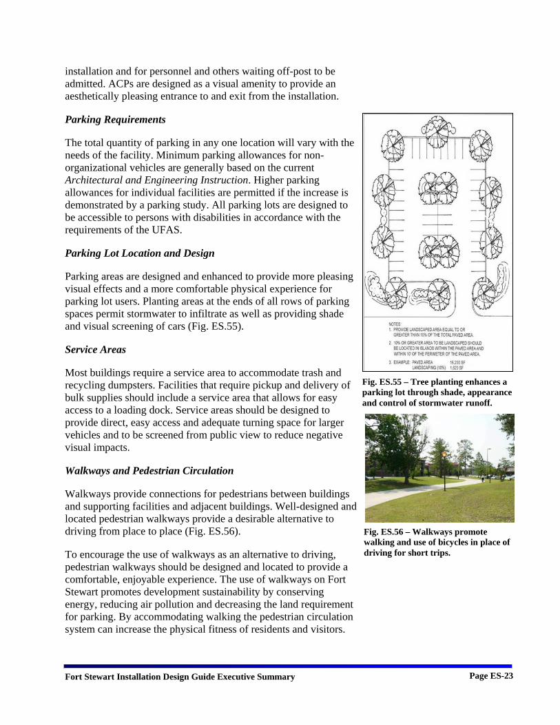
Parking areas are designed and enhanced to provide more pleasing visual effects and a more comfortable physical experience for parking lot users. Planting areas at the ends of all rows of parking spaces permit stormwater to infiltrate as well as providing shade and visual screening of cars (Fig. ES.55).
Service Areas
Most buildings require a service area to accommodate trash and recycling dumpsters. Facilities that require pickup and delivery of bulk supplies should include a service area that allows for easy access to a loading dock. Service areas should be designed to provide direct, easy access and adequate turning space for larger vehicles and to be screened from public view to reduce negative visual impacts.
Walkways and Pedestrian Circulation
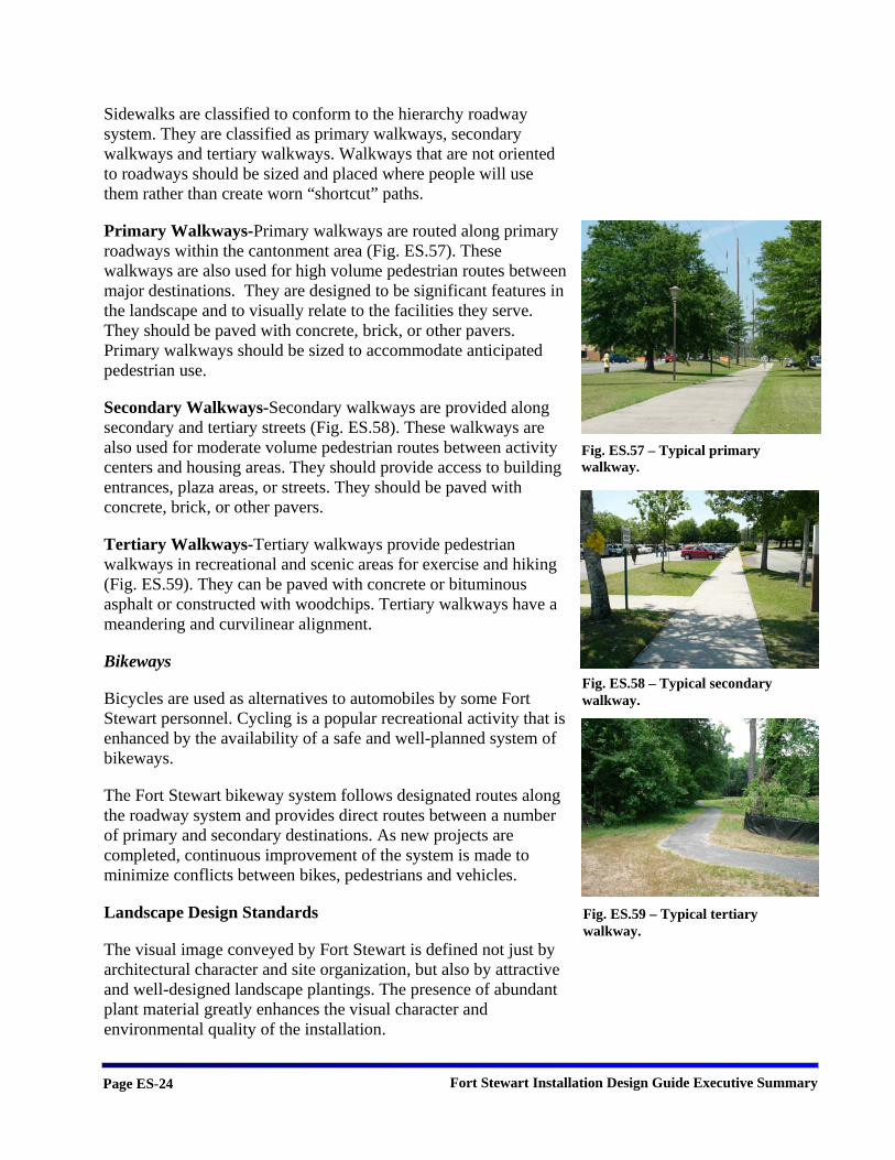
Walkways provide connections for pedestrians between buildings and supporting facilities and adjacent buildings. Well-designed and located pedestrian walkways provide a desirable alternative to driving from place to place (Fig. ES.56).
To encourage the use of walkways as an alternative to driving, pedestrian walkways should be designed and located to provide a comfortable, enjoyable experience. The use of walkways on Fort Stewart promotes development sustainability by conserving energy, reducing air pollution and decreasing the land requirement for parking. By accommodating walking the pedestrian circulation system can increase the physical fitness of residents and visitors.
Fig. ES.55 – Tree planting enhances a parking lot through shade, appearance and control of stormwater runoff.
Fig. ES.56 – Walkways promote walking and use of bicycles in place of driving for short trips.
Fort Stewart Installation Design Guide Executive Summary Page ES-24
Sidewalks are classified to conform to the hierarchy roadway system. They are classified as primary walkways, secondary walkways and tertiary walkways. Walkways that are not oriented to roadways should be sized and placed where people will use them rather than create worn “shortcut” paths.
Primary Walkways-Primary walkways are routed along primary roadways within the cantonment area (Fig. ES.57). These walkways are also used for high volume pedestrian routes between major destinations. They are designed to be significant features in the landscape and to visually relate to the facilities they serve. They should be paved with concrete, brick, or other pavers. Primary walkways should be sized to accommodate anticipated pedestrian use.
Secondary Walkways-Secondary walkways are provided along secondary and tertiary streets (Fig. ES.58). These walkways are also used for moderate volume pedestrian routes between activity centers and housing areas. They should provide access to building entrances, plaza areas, or streets. They should be paved with concrete, brick, or other pavers.
Tertiary Walkways-Tertiary walkways provide pedestrian walkways in recreational and scenic areas for exercise and hiking (Fig. ES.59). They can be paved with concrete or bituminous asphalt or constructed with woodchips. Tertiary walkways have a meandering and curvilinear alignment.
Bikeways
Bicycles are used as alternatives to automobiles by some Fort Stewart personnel. Cycling is a popular recreational activity that is enhanced by the availability of a safe and well-planned system of bikeways.
The Fort Stewart bikeway system follows designated routes along the roadway system and provides direct routes between a number of primary and secondary destinations. As new projects are completed, continuous improvement of the system is made to minimize conflicts between bikes, pedestrians and vehicles.
Landscape Design Standards
The visual image conveyed by Fort Stewart is defined not just by architectural character and site organization, but also by attractive and well-designed landscape plantings. The presence of abundant plant material greatly enhances the visual character and environmental quality of the installation.
Fig. ES.57 – Typical primary walkway.
Fig. ES.58 – Typical secondary walkway.
Fig. ES.59 – Typical tertiary walkway.
Fort Stewart Installation Design Guide Executive Summary Page ES-25
Landscape plantings add an element of human scale to open spaces and can be used functionally to screen undesirable views, buffer winds, visually reinforce the hierarchy of the circulation system and provide a visual transition between dissimilar land uses. Landscape plantings, in combination with stands of native vegetation, provide habitat for wildlife and shade and other environmental benefits for residents, employees and visitors.
Landscape Objectives
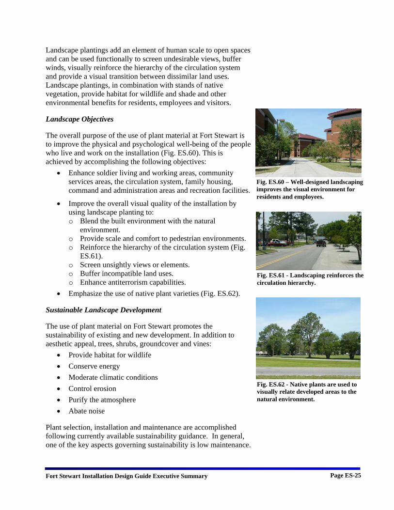
The overall purpose of the use of plant material at Fort Stewart is to improve the physical and psychological well-being of the people who live and work on the installation (Fig. ES.60). This is achieved by accomplishing the following objectives:
• Enhance soldier living and working areas, community services areas, the circulation system, family housing, command and administration areas and recreation facilities.
• Improve the overall visual quality of the installation by using landscape planting to: o Blend the built environment with the natural
environment. o Provide scale and comfort to pedestrian environments. o Reinforce the hierarchy of the circulation system (Fig.
ES.61). o Screen unsightly views or elements. o Buffer incompatible land uses. o Enhance antiterrorism capabilities.
• Emphasize the use of native plant varieties (Fig. ES.62).
Sustainable Landscape Development
The use of plant material on Fort Stewart promotes the sustainability of existing and new development. In addition to aesthetic appeal, trees, shrubs, groundcover and vines:
• Provide habitat for wildlife • Conserve energy • Moderate climatic conditions • Control erosion • Purify the atmosphere • Abate noise
Plant selection, installation and maintenance are accomplished following currently available sustainability guidance. In general, one of the key aspects governing sustainability is low maintenance.
Fig. ES.60 – Well-designed landscaping improves the visual environment for residents and employees.
Fig. ES.61 - Landscaping reinforces the circulation hierarchy.
Fig. ES.62 - Native plants are used to visually relate developed areas to the natural environment.
Fort Stewart Installation Design Guide Executive Summary Page ES-26
Landscape Design Guidelines
Proposed planting designs must be reviewed to ensure that site conditions (soil, topography, adjacent uses and architecture) and climatic criteria (sun, shade and moisture requirements) have been properly considered. The appropriateness of the landscape layout and the selection of plants must also take into account how the area will be used and who will use it. The design concept must also complement adjacent buildings, define outdoor space and control views. Landscape planting plans must be prepared by qualified personnel to provide quality assurance and promote design consistency within each visual zone.
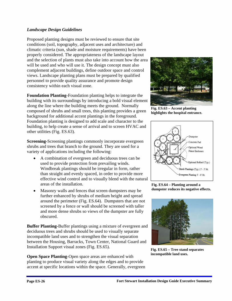
Foundation Planting-Foundation planting helps to integrate the building with its surroundings by introducing a bold visual element along the line where the building meets the ground. Normally composed of shrubs and small trees, this planting provides a green background for additional accent plantings in the foreground. Foundation planting is designed to add scale and character to the building, to help create a sense of arrival and to screen HVAC and other utilities (Fig. ES.63).
Screening-Screening plantings commonly incorporate evergreen shrubs and trees that branch to the ground. They are used for a variety of applications including the following:
• A combination of evergreen and deciduous trees can be used to provide protection from prevailing winds. Windbreak plantings should be irregular in form, rather than straight and evenly spaced, in order to provide more effective wind control and to visually blend with the natural areas of the installation.
• Masonry walls and fences that screen dumpsters may be further enhanced by shrubs of medium height and spread around the perimeter (Fig. ES.64). Dumpsters that are not screened by a fence or wall should be screened with taller and more dense shrubs so views of the dumpster are fully obscured.
Buffer Planting-Buffer plantings using a mixture of evergreen and deciduous trees and shrubs should be used to visually separate incompatible land uses and to strengthen the visual separation between the Housing, Barracks, Town Center, National Guard and Installation Support visual zones (Fig. ES.65).
Open Space Planting-Open space areas are enhanced with planting to produce visual variety along the edges and to provide accent at specific locations within the space. Generally, evergreen
Fig. ES.64 – Planting around a dumpster reduces its negative effects.
Fig. ES.63 – Accent planting highlights the hospital entrance.
Fig. ES.65 – Tree stand separates incompatible land uses.

Fort Stewart Installation Design Guide Executive Summary Page ES-27
trees are used around the perimeter to enclose the open space. Flowering trees and shrubs are planted inside and against the perimeter to add visual interest. Accent trees and shrubs are used in plantings within the open space to draw attention to specific features. Accent plants are placed in groups to increase their visual effect (Fig. ES.66).
Street Trees-Overall, street trees are used to provide visual containment along streets and shade for the pavement, cars and pedestrians. Street tree varieties are selected for specific streets to visually reinforce the identity of the street within the hierarchy of the roadway system. Street trees, in combination with screening along parking lots, reduce the visual dominance of vehicles (Fig. ES.67).
Parking Lot Planting-Parking lots are planted with trees and vegetative screening along the perimeter to improve their appearance, to help define circulation and to reduce heat gain during summer months (Fig. ES.67).
Environmental Control Planting-Landscape plantings can provide environmental benefits, as well as addressing visual concerns. Deciduous shade trees provide shelter from the sun in summer and allow sun to warm buildings and pavement in winter (Fig. ES.68). Mixed plantings of deciduous shrubs and evergreen trees and shrubs to provide sound and dust control along primary and secondary roads. Evergreen trees planted in rows can shelter outdoor areas from wind.
Image Planting-The image of Fort Stewart is formed by the visual impressions that are created by the landscape and buildings on the installation (Fig. ES.69). The most highly visible locations that contribute to the image of the installation are the main gate and Headquarters area, the primary circulation routes and activity nodes such as the PX and Soldier Service Center. Features like static displays and signs that contribute to the installation image are improved by the incorporation of supporting landscape planting.
Entrances to the Installation-The entrances and streetscapes leading up to them are landscaped to develop a strong visual image of the installation. The installation sign and the immediate areas around the Visitor Center and access control points (ACP) are landscaped and highlighted with accent plants to provide year-round visual interest.
Fig. ES.68 – Shade trees shelter as well as visually accent building entrances.
Fig. ES.69 – The landscape image of Fort Stewart is created by the mix of native and planted vegetation.
Fig. ES.67 – View of street trees and parking lot shade trees at the hospital.
Fig. ES.66 – Variety in color and texture in groupings of plants adds interest.
Fort Stewart Installation Design Guide Executive Summary Page ES-28
Xeriscape-Xeriscape, conservation of water and energy through creative and adaptive landscape design, is encouraged at Fort Stewart. Xeriscape landscaping provides attractive solutions that save money, water and maintenance.
Irrigation-Irrigation is generally discouraged at Fort Stewart on the basis that landscaping, once established, should be able to thrive on the naturally available precipitation. Special circumstances where irrigation may be justified will be considered during project planning and design for new projects. No retrofit of landscaping with irrigation is permitted without prior approval through the maintenance and self-help project review process.
Plant Material Selection
Trees, shrubs, ground cover and turf are the major elements in a planting composition. Plant material for landscaping is systematic selected to create a unified composition, emphasize native plants, ensure low maintenance and match the appropriate plants to the land use and site conditions.
Site Elements Design Standards
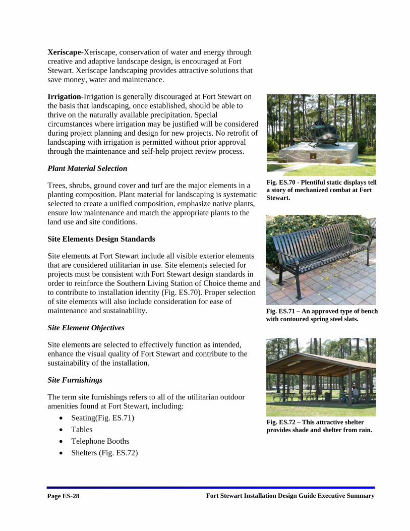
Site elements at Fort Stewart include all visible exterior elements that are considered utilitarian in use. Site elements selected for projects must be consistent with Fort Stewart design standards in order to reinforce the Southern Living Station of Choice theme and to contribute to installation identity (Fig. ES.70). Proper selection of site elements will also include consideration for ease of maintenance and sustainability.
Site Element Objectives
Site elements are selected to effectively function as intended, enhance the visual quality of Fort Stewart and contribute to the sustainability of the installation.
Site Furnishings
The term site furnishings refers to all of the utilitarian outdoor amenities found at Fort Stewart, including:
• Seating(Fig. ES.71) • Tables • Telephone Booths • Shelters (Fig. ES.72)
Fig. ES.72 – This attractive shelter provides shade and shelter from rain.
Fig. ES.71 – An approved type of bench with contoured spring steel slats.
Fig. ES.70 - Plentiful static displays tell a story of mechanized combat at Fort Stewart.
Fort Stewart Installation Design Guide Executive Summary Page ES-29
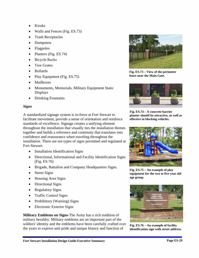
• Kiosks • Walls and Fences (Fig. ES.73) • Trash Receptacles • Dumpsters • Flagpoles • Planters (Fig. ES.74) • Bicycle Racks • Tree Grates • Bollards • Play Equipment (Fig. ES.75) • Mailboxes • Monuments, Memorials, Military Equipment Static
Displays • Drinking Fountains
Signs
A standardized signage system is in-force at Fort Stewart to facilitate movement, provide a sense of orientation and reinforce standards of excellence. Signage creates a unifying element throughout the installation that visually ties the installation themes together and builds a reference and continuity that translates into confidence and reassurance when traveling throughout the installation. There are ten types of signs permitted and regulated at Fort Stewart.
• Installation Identification Signs • Directional, Informational and Facility Identification Signs
(Fig. ES.76) • Brigade, Battalion and Company Headquarters Signs. • Street Signs • Housing Area Signs • Directional Signs • Regulatory Signs • Traffic Control Signs • Prohibitory (Warning) Signs • Electronic Exterior Signs
Military Emblems on Signs-The Army has a rich tradition of military heraldry. Military emblems are an important part of the soldiers' identity and the emblems have been carefully crafted over the years to express unit pride and unique history and function of
Fig. ES.73 – View of the perimeter fence near the Main Gate.
Fig. ES.74 – A concrete barrier planter should be attractive, as well as effective in blocking vehicles.
Fig. ES.75 – An example of play equipment for the two to five year old age group.
Fig. ES.76 – An example of facility identification sign with street address.

Fort Stewart Installation Design Guide Executive Summary Page ES-30
the unit. The care and use of organizational emblems in a signage system can add visual interest as well as build pride and a sense of history.
Department of the Army Plaque-The plaque should be displayed on installation identification signage to emphasize the heritage and professionalism of the United States Army.
Insignias-The use of branch insignia, shoulder sleeve insignia, coat of arms and/or distinctive insignia on headquarters signs is permitted. All military emblems must appear in full color. Motivational symbols or motifs will not be used.
Reduction of Visual Clutter-Over-signing detracts from a uniform sign system and will eventually destroy the integrity of the system.
Lighting
Lighting is a functional requirement of installations that also impacts the visual environment. The site lighting system conveys a sense of order and organization, as well as providing safety. The lighting system provides the proper type of lighting for different lighting requirements and locations. All lighting must be located and selected to prevent undesirable spillover of light into other areas.
Light Fixtures-Five types of lighting fixtures are permitted for site lighting on Fort Stewart.
• Standard Cobrahead Fixture Cut-Off • Premium Cobrahead Fixture Cut-Off • Shoebox Fixture (Fig. ES.77) • Post Top Light Fixture (Fig. ES.78) • Lighted Bollard
Utilities
Utility systems provide the basic infrastructure of power, communication, water and sewer services necessary for the operation of Fort Stewart. Utilities also play a key role in the visual quality of the installation. Their primary impact on the visual quality is the result of the clutter of overhead utility lines and poorly designed storm drainage systems.
Power Distribution-Power distribution lines should be located underground to minimize negative visual impact, reduce
Fig. ES.77 - The approved shoebox fixture.
Fig. ES.78 – The approved Salem Series post top light.
Fort Stewart Installation Design Guide Executive Summary Page ES-31
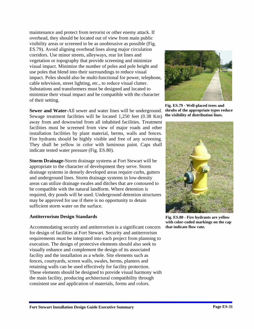
maintenance and protect from terrorist or other enemy attack. If overhead, they should be located out of view from main public visibility areas or screened to be as unobtrusive as possible (Fig. ES.79). Avoid aligning overhead lines along major circulation corridors. Use minor streets, alleyways, rear lot lines and vegetation or topography that provide screening and minimize visual impact. Minimize the number of poles and pole height and use poles that blend into their surroundings to reduce visual impact. Poles should also be multi-functional for power, telephone, cable television, street lighting, etc., to reduce visual clutter. Substations and transformers must be designed and located to minimize their visual impact and be compatible with the character of their setting.
Sewer and Water-All sewer and water lines will be underground. Sewage treatment facilities will be located 1,250 feet (0.38 Km) away from and downwind from all inhabited facilities. Treatment facilities must be screened from view of major roads and other installation facilities by plant material, berms, walls and fences. Fire hydrants should be highly visible and free of any screening. They shall be yellow in color with luminous paint. Caps shall indicate tested water pressure (Fig. ES.80).
Storm Drainage-Storm drainage systems at Fort Stewart will be appropriate to the character of development they serve. Storm drainage systems in densely developed areas require curbs, gutters and underground lines. Storm drainage systems in low-density areas can utilize drainage swales and ditches that are contoured to be compatible with the natural landform. Where detention is required, dry ponds will be used. Underground detention structures may be approved for use if there is no opportunity to detain sufficient storm water on the surface.
Antiterrorism Design Standards
Accommodating security and antiterrorism is a significant concern for design of facilities at Fort Stewart. Security and antiterrorism requirements must be integrated into each project from planning to execution. The design of protective elements should also seek to visually enhance and complement the design of its associated facility and the installation as a whole. Site elements such as fences, courtyards, screen walls, swales, berms, planters and retaining walls can be used effectively for facility protection. These elements should be designed to provide visual harmony with the main facility, producing architectural compatibility through consistent use and application of materials, forms and colors.
Fig. ES.79 - Well-placed trees and shrubs of the appropriate types reduce the visibility of distribution lines.
Fig. ES.80 - Fire hydrants are yellow with color-coded markings on the cap that indicate flow rate.
Fort Stewart Installation Design Guide Executive Summary Page ES-32
Final design decisions to meet security and antiterrorism requirements require coordination among the design disciplines and appropriate functional areas including planners, landscape architects, architects, intelligence personnel, security personnel, facility users and engineers. Design teams consult security personnel to determine whether portions of the design documents are subject to access limitations.
Building Siting and Design Standards
A primary concern at Fort Stewart is the threat of terrorist attack. To minimize the likelihood of mass casualties from terrorist attacks against DoD personnel in the buildings in which they work and live, DoD has developed the Unified Facilities Criteria (UFC) 4-010-01, DoD Minimum Antiterrorism Standards for Buildings. The UFC establishes the minimum building antiterrorism standards for all DoD components. Implementation of the mandatory standards is obligatory for all new construction regardless of the funding source.
Minimum standoff distances and separation are used wherever feasible. If standoff distances can be met, no building hardening measures are required. Appropriate antiterrorism obstacles shall be incorporated into the site design to prevent penetration of an attack vehicle into the secure area perimeter.
When the minimum standoff distances can not be achieved because land is unavailable, the standards allow for building hardening to mitigate blast effects. Costs and requirements for building hardening are addressed in the DoD Security Engineering Manual.
Orientation of Buildings on a Site
The following will be considered in determining the orientation of a building:
• Deny aggressors a clear sightline to the facility from on or off the installation where possible. Protect the facility against surveillance by locating the protected facility outside of the range or out of the view of vantage points.
• Protect against attack by selecting perimeter barriers to block sightlines such as obstruction screens, trees, or shrubs. Non-critical structures or other natural or man-made features can be used to block sightlines.

Fort Stewart Installation Design Guide Executive Summary Page ES-33
• Make the facilities more defensible by positioning facilities to permit building occupants and police to clearly monitor adjacent areas.
• Orient buildings so there are no sides parallel to vehicle approach routes.
• Design vehicular flow to minimize vehicle bomb threats and to avoid high-speed approach into any critical or vulnerable area.
• Avoid siting the facility adjacent to high surrounding terrain, which provides easy viewing of the facility from nearby non-military facilities.
Fencing
Fences are used as protective measures against project-specific threats. They are most appropriately used to define boundaries and to deter penetration of a secure area (Fig. ES.81). A fence will assist in controlling and screening authorized access to a secured area. Fences also serve the following purposes:
• Platform for an Intrusion Detection System. • Screen against explosive projectiles. • Prevent entry by vehicles, when reinforced to do so.
Landscape Considerations
The landscape design should enhance the overall attractiveness of the facility while still providing or enhancing the objective level of security. The following guidelines should be applied to the siting and landscaping of facilities at Fort Stewart:
• Establish clear zones along both sides of security fencing in which vegetation does not exceed four inches in height (Fig. ES.82).
• Strategically locate trees and planters to prevent penetration of an attack vehicle into the secure area perimeter.
• Use vegetative groupings and earth berms to reduce the effects of external blast forces and to prevent vehicles from penetrating building standoff distances (Fig. ES.83).
• Use plant material to provide visual concealment. • Use dense, thorn-bearing plant material to create natural
barriers to deter aggressors. • Outdoor play and recreation areas should be screened from
viewing from locations off the installation.
Fig. ES.81 – Fencing provides a reliable barrier to unauthorized entry.
Fig. ES.82 – Perimeter fencing is flanked by cleared areas.
Fig. ES.83 – An earth berm between a building and adjacent parking lots or roads prevents vehicles from approaching the building.
Fort Stewart Installation Design Guide Executive Summary Page ES-34
• In the placement of signs, direct people first to a community support or information center to obtain directions to high security activities.
• Place trash containers as far away from buildings as possible.
• Ensure that vegetation and site features within 33 feet (10 meters) of inhabited buildings do not conceal from observation objects of 6 inches (150mm) in height.
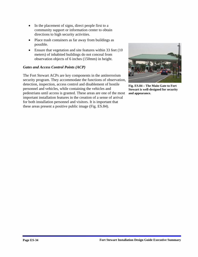
Gates and Access Control Points (ACP)
The Fort Stewart ACPs are key components in the antiterrorism security program. They accommodate the functions of observation, detection, inspection, access control and disablement of hostile personnel and vehicles, while containing the vehicles and pedestrians until access is granted. These areas are one of the most important installation features in the creation of a sense of arrival for both installation personnel and visitors. It is important that these areas present a positive public image (Fig. ES.84).
Fig. ES.84 – The Main Gate to Fort Stewart is well-designed for security and appearance.