formula sae racecar driver aids project 05101 ryan neward henry berg tim falkiewicz nick lehner...
Post on 20-Dec-2015
217 views
TRANSCRIPT

Formula SAE Racecar Formula SAE Racecar Driver AidsDriver Aids
Project 05101Project 05101
Ryan NewardRyan NewardHenry BergHenry Berg
Tim FalkiewiczTim FalkiewiczNick LehnerNick Lehner
Anthony MagagnoliAnthony MagagnoliDoug PayneDoug PayneJohn SchnurrJohn Schnurr

BackgroundBackground Formula SAE team – Formula SAE team – comprised of SAE comprised of SAE
student members.student members.• Objective: Objective: to build a Formula style race car, in the to build a Formula style race car, in the
period of about one year, to participate in international period of about one year, to participate in international competition where they must compete in a variety of competition where they must compete in a variety of static and dynamic events.static and dynamic events.
Project 05101: Formula SAE – Driver Project 05101: Formula SAE – Driver AidsAids• Objective: Objective: to add paddle and button shifters to the to add paddle and button shifters to the
steering wheel so that the driver does not have to steering wheel so that the driver does not have to remove his hands from the wheel. The gear shift will be remove his hands from the wheel. The gear shift will be actuated by a pneumatic system, which will allow for actuated by a pneumatic system, which will allow for other systems to be integrated; including flat shift and other systems to be integrated; including flat shift and automatic up-shift systems.automatic up-shift systems.

TeamTeam
John Schnurr - EE
Nick Lehner - ME
Team Leader
Ryan Neward - ME
Anthony Magagnoli - ME
Doug Payne - ME
Henry Berg - EE
Mechanical Aspects
Electrical Aspects
Circuit Design
Pneumatic System
Steering Wheel Design
Controller
Overall Project
Needs
Scheduling
Tim Falkiewicz - ME

SD1 ScheduleSD1 Schedule

Current Issues with the CarCurrent Issues with the Car
Driver must remove hands from Driver must remove hands from steering wheel to shift gearssteering wheel to shift gears
Difficult to get optimal wheel spin Difficult to get optimal wheel spin when launching the carwhen launching the car
Seating position relative to the Seating position relative to the steering wheelsteering wheel

ConceptsConcepts
Types of Driver Aids InvestigatedTypes of Driver Aids Investigated
Types of Traction Control Types of Traction Control InvestigatedInvestigated
Types of Paddle Shift Actuation Types of Paddle Shift Actuation InvestigatedInvestigated
Types of Driver Aids InvestigatedTypes of Driver Aids Investigated
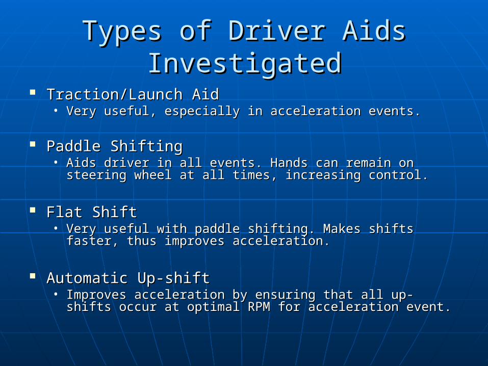
Traction/Launch AidTraction/Launch Aid• Very useful, especially in acceleration events.Very useful, especially in acceleration events.
Paddle ShiftingPaddle Shifting• Aids driver in all events. Hands can remain on steering Aids driver in all events. Hands can remain on steering
wheel at all times, increasing control.wheel at all times, increasing control.
Flat ShiftFlat Shift• Very useful with paddle shifting. Makes shifts faster, Very useful with paddle shifting. Makes shifts faster,
thus improves acceleration.thus improves acceleration.
Automatic Up-shiftAutomatic Up-shift• Improves acceleration by ensuring that all up-shifts Improves acceleration by ensuring that all up-shifts
occur at optimal RPM for acceleration event.occur at optimal RPM for acceleration event.
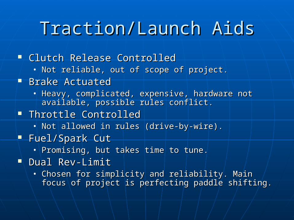
Traction/Launch AidsTraction/Launch Aids Clutch Release ControlledClutch Release Controlled
• Not reliable, out of scope of project.Not reliable, out of scope of project. Brake ActuatedBrake Actuated
• Heavy, complicated, expensive, hardware not available, Heavy, complicated, expensive, hardware not available, possible rules conflict.possible rules conflict.
Throttle ControlledThrottle Controlled• Not allowed in rules (drive-by-wire).Not allowed in rules (drive-by-wire).
Fuel/Spark CutFuel/Spark Cut• Promising, but takes time to tune.Promising, but takes time to tune.
Dual Rev-LimitDual Rev-Limit• Chosen for simplicity and reliability. Main focus of Chosen for simplicity and reliability. Main focus of
project is perfecting paddle shifting.project is perfecting paddle shifting.

Shift Actuation MethodsShift Actuation Methods
Mechanical LinkageMechanical Linkage• Does not allow for automatic up-shift.Does not allow for automatic up-shift.
Electric SolenoidsElectric Solenoids• Requires too much current.Requires too much current.
Electro-HydraulicElectro-Hydraulic• Too complicated, drains horsepower or current.Too complicated, drains horsepower or current.
Electro-PneumaticElectro-Pneumatic• Does not use horsepower or a large amount of Does not use horsepower or a large amount of
current. Simpler, and allows for automatic up-current. Simpler, and allows for automatic up-shift.shift.

Initial FeasibilityInitial FeasibilityFeasibility
Criteria
Time Frame 3 3 2 2 1 3 3 3 3
Affordable 3 2 1 2 1 3 3 4 3
Sufficient Skills 3 3 2 2 1 3 3 4 3
Will it require too much current 3 1 2 2 3 2 3 2 2
Finite Life 3 3 3 2 3 3 3 3 3
Reliable 3 3 2 2 2 4 2 5 4
Robust (Durable) 3 2 2 2 3 4 4 4 2
Can be combined with another technology
3 5 5 5 3 4 3 5 4
Technologically advanced 3 4 5 5 5 4 5 2 4
Simplicity for driver 3 3 3 3 5 3 2 5 5
Replace an existing part
3 3 3 3 1 1 1 1 1
Ease of replacement
3 3 1 2 1 3 3 3 2
Make the car faster 3 3 3 3 4 5 5 4 4
Appearance 3 4 2 2 2 4 4 3 3
Weight 3 4 1 2 1 5 3 5 4
Safety 3 3 2 3 2 4 3 4 5
Packaging 3 5 1 2 2 5 3 5 5
Totals 51 54 40 44 40 60 53 62 57
Average 3 3.18 2.35 2.59 2.35 3.53 3.12 3.65 3.35
Traction Control
Turbo Motor
Launch Control
F-1 Flat ShiftMechanical ElectricElectro
HydraulicElectro
Pneumatic

Sponsor GoalsSponsor Goals
Shift the gearbox without driver Shift the gearbox without driver removing hands from steering wheel removing hands from steering wheel using a non electrical methodusing a non electrical method
Electronic flat shiftElectronic flat shift Automatic up-shiftAutomatic up-shift Launch procedure for acceleration Launch procedure for acceleration
runrun

DSMDSM
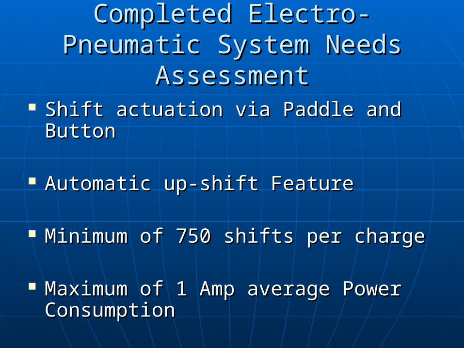
Completed Electro-Pneumatic Completed Electro-Pneumatic System Needs AssessmentSystem Needs Assessment
Shift actuation via Paddle and Button Shift actuation via Paddle and Button
Automatic up-shift Feature Automatic up-shift Feature
Minimum of 750 shifts per chargeMinimum of 750 shifts per charge
Maximum of 1 Amp average Power Maximum of 1 Amp average Power ConsumptionConsumption

Pneumatic Subsystem Pneumatic Subsystem Component ConstraintsComponent Constraints
Compressed Gas Storage VesselCompressed Gas Storage Vessel• 4,500 psi, 44 cubic inches, Light Weight4,500 psi, 44 cubic inches, Light Weight
Manifold and SolenoidManifold and Solenoid• Cumulative Power drain under 1 amp. 3-positon 4-way Cumulative Power drain under 1 amp. 3-positon 4-way
configuration configuration
Pneumatic CylinderPneumatic Cylinder• Double Acting, with minimum force application of 20 lbs Double Acting, with minimum force application of 20 lbs
at a 1.6 inch moment armat a 1.6 inch moment arm
Pressure RegulatorPressure Regulator• Pressure range from 60-150 psiPressure range from 60-150 psi

Electrical SubsystemElectrical Subsystem Enable SwitchesEnable Switches
• Automatic up-shift, Launch ControlAutomatic up-shift, Launch Control Gear Selection MethodGear Selection Method
• Paddle and ButtonPaddle and Button Gear IndicatorGear Indicator
• Dash hoop mounted LED arrayDash hoop mounted LED array Input/Output CapabilityInput/Output Capability
• Transmission Drum Encoder, Relays, SwitchesTransmission Drum Encoder, Relays, Switches Intuitive ProgramIntuitive Program
• Ease of ModificationEase of Modification Power ConstraintsPower Constraints
• 1 amp cumulatively1 amp cumulatively

Preliminary DesignPreliminary Design
0
1
2
3
4
5
6
7
8
9
10
11
12
13
14
15
AIR TANKRegulator
ControlValve
Cylinder
Transmission
+12V
12V
7.7Ohms
100Ohms
RPMSensor
3.5k Ohms
2.5kOhms
AutronicECU
FuelController
Fuel Injector
SparkCoils
Coolent TempSensor
+12V
100Ohms
6 17
Down Shift Up Shift
Controller
GearPositionSensor
Rev LimiterActivation
Switch
Flat Shift ActivationSwitches
Automatic Up-Shift Activation
Switch
GearDisplay
9V
Relay
Relay
Relay
Relay
Relay
Vcc
470 Ohms
470 Ohms
470 Ohms
470 Ohms
470 Ohms
470 Ohms

Paddle/Button ShiftersPaddle/Button Shifters Paddles and buttons are built into the steering wheelPaddles and buttons are built into the steering wheel Driver operates a button or paddle to signal a shiftDriver operates a button or paddle to signal a shift Controller receives shift signalController receives shift signal Controller activates pneumatic systemController activates pneumatic system
Down Shift Up Shift0
1
2
3
4...
13
14
15
7.7Ohms
100Ohms
Controller
9V
AIR TANKRegulator
ControlValve
Transmission
GearPositionSensor
Relay
Relay
+12V
+12V

Flat ShiftingFlat Shifting Controller receives up-shift Controller receives up-shift
signalsignal Controller then signals a Controller then signals a
relay that will cut the relay that will cut the power to the fuel injectorpower to the fuel injector
Controller signals another Controller signals another relay to break the coils relay to break the coils path to groundpath to ground
After the shift is completed After the shift is completed the relays are returned to the relays are returned to their original position and their original position and normal engine operation normal engine operation resumesresumes
0
1
2
3
4
5
6
7...
7.7Ohms
100Ohms
Controller
9V
Flat Shift ActivationSwitches
FuelController
Fuel Injector
Relay
AutronicECU
SparkCoils
Relay
+12V

Automatic Up-ShiftingAutomatic Up-Shifting A signal is sent from A signal is sent from
the RPM sensor to the the RPM sensor to the controllercontroller
The signal is a square The signal is a square wave with a frequency wave with a frequency that varies in that varies in proportion to the RPMproportion to the RPM
When a specified RPM When a specified RPM is reached the is reached the controller activates controller activates the pneumatic system the pneumatic system and an up-shift occursand an up-shift occurs
0
1
2
3
4
5...
7.7Ohms
100Ohms
Controller
9V
RPMSensor
3.5k Ohms
2.5kOhms
Automatic Up-Shift Activation
Switch
+12V

Two Stage Rev LimiterTwo Stage Rev Limiter System is activated by System is activated by
holding the rev limiter holding the rev limiter activation buttonactivation button
Relay connects the coolant Relay connects the coolant temperature input of the temperature input of the ECU to groundECU to ground
ECU sees the coolant ECU sees the coolant temperature as 127temperature as 127°C°C
Rev limit table is setup so Rev limit table is setup so that at this temperature that at this temperature the maximum RPM are the maximum RPM are limited limited
When activation button is When activation button is released the engine is released the engine is allowed to resume normal allowed to resume normal operationoperation Autronic
ECU
Coolent TempSensor
+12V
100Ohms
6 17
Rev LimiterActivation
Switch
Relay

Gear IndicatorGear Indicator When the car is When the car is
started the controller started the controller reads the current gear reads the current gear from the gear sensorfrom the gear sensor
The LEDs The LEDs corresponding to that corresponding to that gear are illuminatedgear are illuminated
After a gear shift After a gear shift occurs the controller occurs the controller updates the LED updates the LED display with the display with the current gear current gear
6
7
8
9
10
11
12
13
7.7Ohms
100Ohms
Controller
9V
12V
Gear PositionSensor Output
GearDisplay
470 Ohms
470 Ohms
470 Ohms
470 Ohms
470 Ohms
470 Ohms

Correct Shift DetectionCorrect Shift Detection After the controller After the controller
requests a gear shift it requests a gear shift it reads the gear position reads the gear position from the gear sensorfrom the gear sensor
If a gear change did not If a gear change did not occur the controller occur the controller requests another shiftrequests another shift
This continues until the This continues until the correct gear is reached or correct gear is reached or a set number of attempts a set number of attempts have been madehave been made
This system also prevents This system also prevents an impossible shift request an impossible shift request e.g. an up-shift request e.g. an up-shift request when the car is in top gearwhen the car is in top gear
Down Shift Up Shift0
1
2
3
4...
13
14
15
7.7Ohms
100Ohms
Controller
9V
AIR TANKRegulator
ControlValve
Transmission
GearPositionSensor
Relay
Relay
+12V
+12V
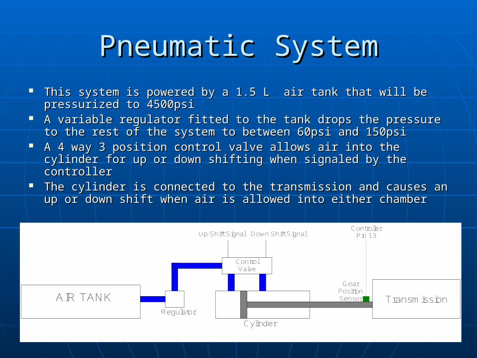
Pneumatic SystemPneumatic System This system is powered by a 1.5 L air tank that will be This system is powered by a 1.5 L air tank that will be
pressurized to 4500psipressurized to 4500psi A variable regulator fitted to the tank drops the pressure to A variable regulator fitted to the tank drops the pressure to
the rest of the system to between 60psi and 150psithe rest of the system to between 60psi and 150psi A 4 way 3 position control valve allows air into the cylinder A 4 way 3 position control valve allows air into the cylinder
for up or down shifting when signaled by the controllerfor up or down shifting when signaled by the controller The cylinder is connected to the transmission and causes an The cylinder is connected to the transmission and causes an
up or down shift when air is allowed into either chamber up or down shift when air is allowed into either chamber
AIR TANKRegulator
ControlValve
Cylinder
Transmission
GearPositionSensor
Up-Shift Signal Down Shift SignalController
Pin 13

Flow ChartsFlow Charts
At y RPM, computer sendssignal to upshift to
“actuator” solenoid manifold
Sends electrical signal to“actuator” solenoid manifold
Sends electrical signal toAutronic to momentarily
retard engine (fuel/spark)
Signal received opens valve
Release pressurecylinder is forced in x
direction
Causes rotation of shiftershaft theta degrees
Release pressurecylinder is forced in -x
direction
Causes rotation of shiftershaft -theta degrees
Sends electrical signal to“actuator” solenoid manifold
Desired highergear engaged?
Up/down shiftDiver input
Signal received opens valve
Desired lowergear engaged?
Start
Upshift Switchis closed?
yes
no
Up shift
Down shift
no no
yes
Resume Fuel and Spark yes
Autronic limits redline to
preprogrammed RPM limit
Driver launches
Full redline resumes
Launch control switch activated
yes
yes
no
Driver releases switch
Launch Control Shift System

Analysis & SynthesisAnalysis & Synthesis
Finite life analysisFinite life analysis• Electrical Electrical
componentscomponents Component sizingComponent sizing
• Force requirementForce requirement• Tank and cylinder Tank and cylinder
dimension variationdimension variation
2186

BudgetBudgetComponent Supplier Price
Regulator Paintball supply shop $65.00
Gas Tank Paintball supply shop $70.00
Cylinder, 6498K429 McMaster Carr $17.04
solenoid IR ARO $125.65
Control Board Parallax $100.00
Coil to steering wheel Digikey $30.00
Buttons Grainger $20.00
wires, air lines, fittings Grainger $30.00
shift potentiometer Grainger $60.00
Total= $517.69

Future PlansFuture Plans
Finished, working system in MayFinished, working system in May
Paddle shifters - Majority of timePaddle shifters - Majority of time• Pneumatic systemPneumatic system
Flat shift - TestingFlat shift - Testing Automatic Up-shift - IntegrationAutomatic Up-shift - Integration Launch Procedure - TestingLaunch Procedure - Testing

SD2 ScheduleSD2 Schedule

Questions?Questions?

Options for Compressed GasOptions for Compressed Gas
Carbon dioxideCarbon dioxide• Freezes at relatively high temperatureFreezes at relatively high temperature• Liquid when compressedLiquid when compressed
High pressure airHigh pressure air• Can be filled to pressures of 4500 p.s.i.Can be filled to pressures of 4500 p.s.i.• CleanClean
ArgonArgon• Same properties as high pressure airSame properties as high pressure air• Can only be filled to 2200 p.s.i.Can only be filled to 2200 p.s.i.

Launch Control FeasibilityLaunch Control FeasibilityFeasibility Criteria
2 Step Rev
Limiter
Clutch Release Control
Traction Control
(cut fuel/spark)
Traction Control (apply brake)
Drive By
Wire
Time Frame 3 2 2 1 2Reliability 3 1 2 1 2Affordable 3 2 2 1 1Technologically Advanced
3 4 4 5 5
Sufficient Skills 3 2 2 1 2
Use existing parts 3 1 2 0 1
Make the car faster
3 4 5 2 4
Simplicity for driver
3 3 3 2 3
Durable 3 2 3 1 2Weight 3 2 3 1 3Safety 3 2 3 1 1Packaging 3 2 3 1 3Available hardware
3 2 3 1 1
Total 39 29 37 18 30Average 3.00 2.23 2.85 1.38 2.31
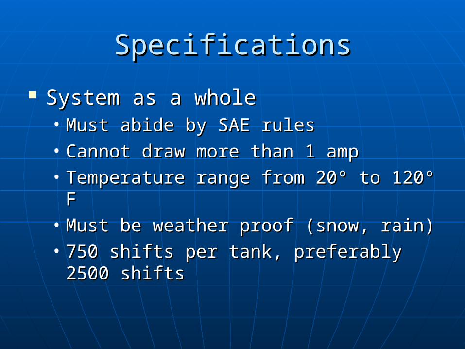
SpecificationsSpecifications
System as a wholeSystem as a whole• Must abide by SAE rulesMust abide by SAE rules• Cannot draw more than 1 ampCannot draw more than 1 amp• Temperature range from 20º to 120º F Temperature range from 20º to 120º F • Must be weather proof (snow, rain) Must be weather proof (snow, rain) • 750 shifts per tank, preferably 2500 750 shifts per tank, preferably 2500
shifts shifts
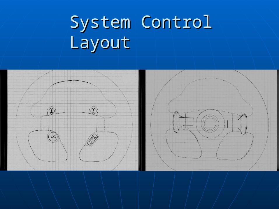
System Control LayoutSystem Control Layout