formal translation of iec 61131-3 function block diagrams...
TRANSCRIPT
Formal Translation of IEC 61131-3 FunctionBlock Diagrams to PVS with Nuclear
Application
Josh Newell1(B), Linna Pang1, David Tremaine1, Alan Wassyng2,and Mark Lawford2
1 Systemware Innovation Corporation, Toronto M4P 1E4, Canada{jnewell,lpang,tremaine}@swi.com
2 McMaster Centre for Software Certification, McMaster University,Hamilton L8S 4K1, Canada
{wassyng,lawford}@mcmaster.ca
Abstract. The trip computers for the two reactor shutdown systems ofthe Ontario Power Generation (OPG) Darlington Nuclear Power Gen-erating Station (DNGS) are being refurbished due to hardware obsoles-cence. For one of the systems, the general purpose computer originallyused is being replaced by a programmable logic controller (PLC). Thetrip computer application software has been rewritten using functionblock diagrams (FBDs), a commonly used PLC programming languagedefined in the IEC 61131-3 standard. The replacement project’s qual-ity assurance program requires that formal verification be performed tocompare the FBDs against a formal software requirements specification(SRS) written using tabular expressions (TEs). The PVS theorem prov-ing tool is used in the formal verification. Custom tools developed forOPG are used to translate TEs and FBDs into PVS code. In this paper,we present a method to rigorously translate the graphical FBD languageto a mathematical model in PVS using an abstract syntax to representthe FBD constructs. We use an example from the replacement projectto demonstrate the use of the model to translate a FBD module into aPVS specification.
Keywords: Safety critical systems · IEC 61131-3 · Function blockdiagrams · Formal specification · PVS · Tabular expressions
1 Introduction
Many industrial, safety-critical control systems leverage programmable technolo-gies for their flexibility and scalability. The use of programmable technologiesfor safety-critical design is now commonplace in nuclear, aerospace and automo-tive applications, and formal methods can play an important role in ensuringthat those applications are safe. In the aviation domain, DO-178C [2] advocatesthe use of formal methods to create mathematical models for the specification
c© Springer International Publishing Switzerland 2016S. Rayadurgam and O. Tkachuk (Eds.): NFM 2016, LNCS 9690, pp. 206–220, 2016.DOI: 10.1007/978-3-319-40648-0 16
Formal Translation of IEC 61131-3 Function Block Diagrams to PVS 207
and analysis of system behaviour. In the nuclear industry, IEEE 7-4.3.2 [1] listsacceptance criteria for mission- or safety- critical systems that practitioners needto comply with. In the context of formal methods, two important criteria are:(1) the software requirements are both precise and complete; and (2) the softwareimplementation is correct with respect to specified behaviour. In the Canadiannuclear industry, CE-1001-STD [7] governs the software engineering of safetycritical applications. It prescribes not only the formal specification of require-ments and design, but also the formal proof of correctness of implementationagainst requirements. Traditionally, CE-1001-STD has been applied to generalpurpose computer languages. It is now being applied to the application-orientedlanguage paradigm of programmable logic controllers (PLCs). PLCs provide ahigher level of abstraction for the programmer via a set of built-in hierarchicalfunction blocks (FBs) that can be safety certified for use in critical applications.
The Ontario Power Generation (OPG) Darlington Nuclear Generating Sta-tion (DNGS) in Ontario, Canada uses two diverse, computerised special safetysystems for emergency shutdown of the reactor. These are referred to as Shut-down System One and Two (i.e., SDS1 and SDS2). They were completed inthe early 1990s and are based on an arrangement of real-time general purposecomputers. Each SDS has three redundant trip computers (TCs) in a 2-out-of-3 voting configuration. The TCs are categorized as safety critical and wereengineered in compliance with CE-1001-STD, which defines a comprehensiveset of development, verification and validation processes. Formal requirementsand design specification were developed and documented using tabular expres-sions (TEs) [13]. In addition to various review and overlapping testing processes,formal proof of correctness was performed using a theorem prover Prototype Ver-ification System PVS [9].
Currently, SDS1 and SDS2 are being refurbished to extend the nuclear plant’slife and both hardware platforms are being replaced. A safety-certified PLCcompliant with IEC 61131-3 [4] was selected for the SDS1 TC replacement. Aswith the original project, the software requirements are specified using TEs, butthe software design is now specified in a function block diagram (FBD) languageusing built-in IEC 61131-3 FBs provided by a PLC vendor1,2. Using the PLCplatform, the detailed design automatically generates executable code. PVS isused to formally verify the design against the requirements.
PVS provides an integrated environment with mechanized support for thesyntax and semantics of TEs and (higher-order) predicates. Based on [10], anapproach was developed for the replacement project to support the formal verifi-cation of FBDs. The process is as follows: (1) the trip computer design, describedin a collection of FBDs, is translated into PVS; (2) the requirements described intabular expressions are translated into PVS; and (3) formal proofs for systematicdesign verification are automated using PVS.
1 A small portion of the software design is written using structured text (ST), butthat is not relevant to the subject of this paper.
2 The use of IEC 61131-3 compliant built-in FBs eased formal specification and sub-sequent verification of their behavior; one of many PLC qualification activities.

208 J. Newell et al.
Fig. 1. Framework diagram
Step (1) of the process is the subject of this paper and is based on ourexperience in the replacement project. An abstract syntax is created to representthe constructs of a FBD and rigorous translation rules are defined for the generaltranslation of FBDs into PVS specifications.
Figure 1 summarizes the overall verification process and contributions. Asshown on the left, the requirements are documented using tabular expressions.The design is written in a FBD language that is complaint with IEC 61131-3. Inthe center of the diagram, we highlight our main contributions within a dashedrectangle. We define an abstract syntax for FBDs using a FBD design as input.With values from the abstract syntax as input, we define an attribute map andlabelled directed graph to represent relationships in the FBD. Given an attributemap and graph, we define an additional data structure, block groups, to reducethe complexity of PVS translation. Shown on the right side of Fig. 1, the require-ments are formalized in PVS whereas the FBD specification is produced fromour methodology. Based on [10], our technique also produces the consistencytheorems3 for FBDs, which are verified manually in PVS. The correctness the-orems are manually specified and verified in PVS. The future automation ofconsistency and correctness proofs is discussed in Sect. 8.
2 Preliminaries
2.1 Tabular Expressions
Tabular expressions [13] (a.k.a., function tables) are a proven and effective app-roach for describing conditionals and relations, and thus are ideal for document-ing many system requirements. They are arguably easier to comprehend and to
3 A FBD design is consistent if for every input there exists an output that satisfies theinternal relationships. Otherwise, a FBD design trivially satisfies any requirement.
Formal Translation of IEC 61131-3 Function Block Diagrams to PVS 209
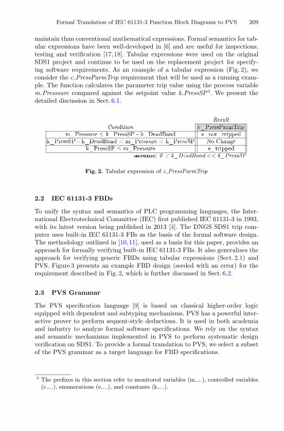
maintain than conventional mathematical expressions. Formal semantics for tab-ular expressions have been well-developed in [6] and are useful for inspections,testing and verification [17,18]. Tabular expressions were used on the originalSDS1 project and continue to be used on the replacement project for specify-ing software requirements. As an example of a tabular expression (Fig. 2), weconsider the c PressParmTrip requirement that will be used as a running exam-ple. The function calculates the parameter trip value using the process variablem Presssure compared against the setpoint value k PressSP4. We present thedetailed discussion in Sect. 6.1.
Fig. 2. Tabular expression of c PressParmTrip
2.2 IEC 61131-3 FBDs
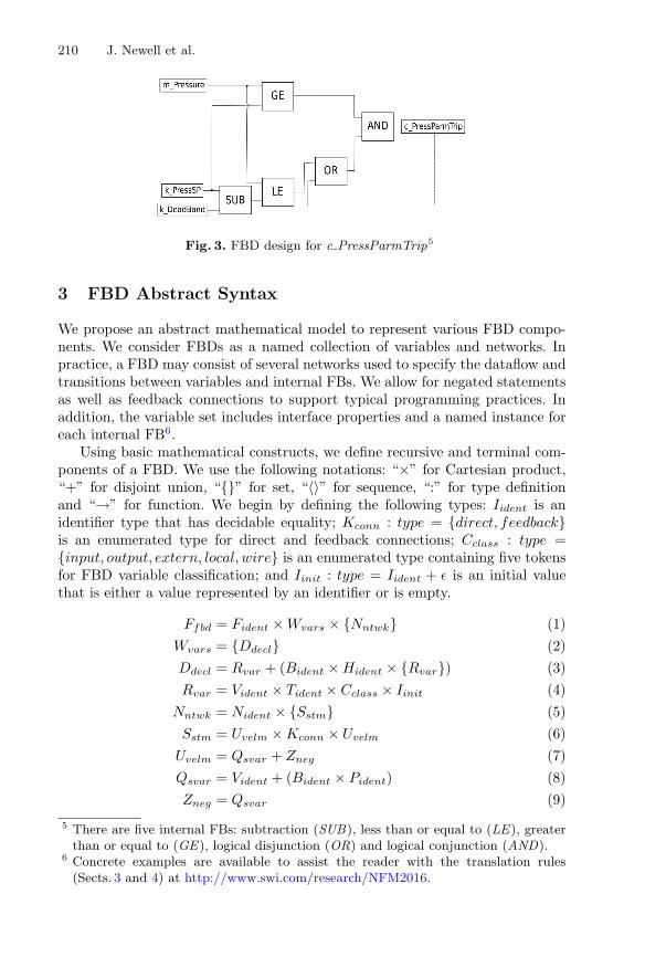
To unify the syntax and semantics of PLC programming languages, the Inter-national Electrotechnical Committee (IEC) first published IEC 61131-3 in 1993,with its latest version being published in 2013 [4]. The DNGS SDS1 trip com-puter uses built-in IEC 61131-3 FBs as the basis of the formal software design.The methodology outlined in [10,11], used as a basis for this paper, provides anapproach for formally verifying built-in IEC 61131-3 FBs. It also generalizes theapproach for verifying generic FBDs using tabular expressions (Sect. 2.1) andPVS. Figure 3 presents an example FBD design (seeded with an error) for therequirement described in Fig. 2, which is further discussed in Sect. 6.2.
2.3 PVS Grammar
The PVS specification language [9] is based on classical higher-order logicequipped with dependent and subtyping mechanisms. PVS has a powerful inter-active prover to perform sequent-style deductions. It is used in both academiaand industry to analyze formal software specifications. We rely on the syntaxand semantic mechanisms implemented in PVS to perform systematic designverification on SDS1. To provide a formal translation to PVS, we select a subsetof the PVS grammar as a target language for FBD specifications.
4 The prefixes in this section refer to monitored variables (m ...), controlled variables(c ...), enumerations (e ...), and constants (k ...).
210 J. Newell et al.
Fig. 3. FBD design for c PressParmTrip5
3 FBD Abstract Syntax
We propose an abstract mathematical model to represent various FBD compo-nents. We consider FBDs as a named collection of variables and networks. Inpractice, a FBD may consist of several networks used to specify the dataflow andtransitions between variables and internal FBs. We allow for negated statementsas well as feedback connections to support typical programming practices. Inaddition, the variable set includes interface properties and a named instance foreach internal FB6.
Using basic mathematical constructs, we define recursive and terminal com-ponents of a FBD. We use the following notations: “×” for Cartesian product,“+” for disjoint union, “{}” for set, “〈〉” for sequence, “:” for type definitionand “→” for function. We begin by defining the following types: Iident is anidentifier type that has decidable equality; Kconn : type = {direct, feedback}is an enumerated type for direct and feedback connections; Cclass : type ={input, output, extern, local, wire} is an enumerated type containing five tokensfor FBD variable classification; and Iinit : type = Iident + ε is an initial valuethat is either a value represented by an identifier or is empty.
Ffbd = Fident × Wvars × {Nntwk} (1)Wvars = {Ddecl} (2)Ddecl = Rvar + (Bident × Hident × {Rvar}) (3)Rvar = Vident × Tident × Cclass × Iinit (4)
Nntwk = Nident × {Sstm} (5)Sstm = Uvelm × Kconn × Uvelm (6)
Uvelm = Qsvar + Zneg (7)Qsvar = Vident + (Bident × Pident) (8)Zneg = Qsvar (9)
5 There are five internal FBs: subtraction (SUB), less than or equal to (LE), greaterthan or equal to (GE), logical disjunction (OR) and logical conjunction (AND).
6 Concrete examples are available to assist the reader with the translation rules(Sects. 3 and 4) at http://www.swi.com/research/NFM2016.
Formal Translation of IEC 61131-3 Function Block Diagrams to PVS 211
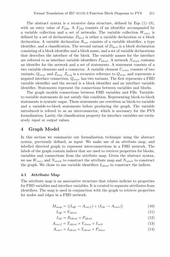
The abstract syntax is a recursive data structure, defined by Eqs. (1)–(9),with an entry value of Ffbd. A Ffbd consists of an identifier accompanied bya variable collection and a set of networks. The variable collection Wvars isdefined by a set of declarations; Ddecl is either a variable declaration or a blockdeclaration. A variable declaration Rvar consists of a variable identifier, a typeidentifier, and a classification. The second variant of Ddecl is a block declarationconsisting of a block identifier and a block name, and a set of variable declarationsthat describes the interface of the block. The variable names for the interfaceare referred to as interface variable identifiers Pident. A network Nntwk containsan identifer for the network and a set of statements. A statement consists of atwo variable elements and a connector. A variable element Uvelm consists of twovariants, Qsvar and Zneg. Zneg is a recursive reference to Qsvar and represents anegated interface connection. Qsvar has two variants. The first represents a FBDvariable identifier and the second is a block identifier and an interface variableidentifier. Statements represent the connections between variables and blocks.
The graph models connections between FBD variables and FBs. Variable-to-variable statements do not satisfy this condition. Representing block-to-blockstatements is syntatic sugar. These statements are rewritten as block-to-variableand a variable-to-block statements before producing the graph. The variableintroduced is refered to as an interconnector, which is necessary for the PVSformalization. Lastly, the classification property for interface variables are exclu-sively input or output values.
4 Graph Model
In this section we summarize our formalization technique using the abstractsyntax, previously defined, as input. We make use of an attribute map, andlabelled directed graph to represent interconnections in a FBD network. Thelabels of the graph contain indices that are used to retrieve properties for blocks,variables and connections from the attribute map. Given the abstract syntax,we use Wvars and Nntwk to construct the attribute map and Nntwk to constructthe graph. We chose to use variable identifiers Iident to construct the indices.
4.1 Attribute Map
The attribute map is an associative structure that relates indicies to propertiesfor FBD variables and interface variables. It is created to separate attributes fromidentifiers. The map is used in conjunction with the graph to retrieve propertiesfor nodes and edges in a FBD network.
Mmap = 〈(Iidf → Avarf ) + (Iidi → Avari)〉 (10)Iidf = Vident (11)Iidi = Bident × Pident (12)
Avarf = Tident × Vclass × Iinit (13)Avari = Iident × Tident × Pclass (14)
212 J. Newell et al.
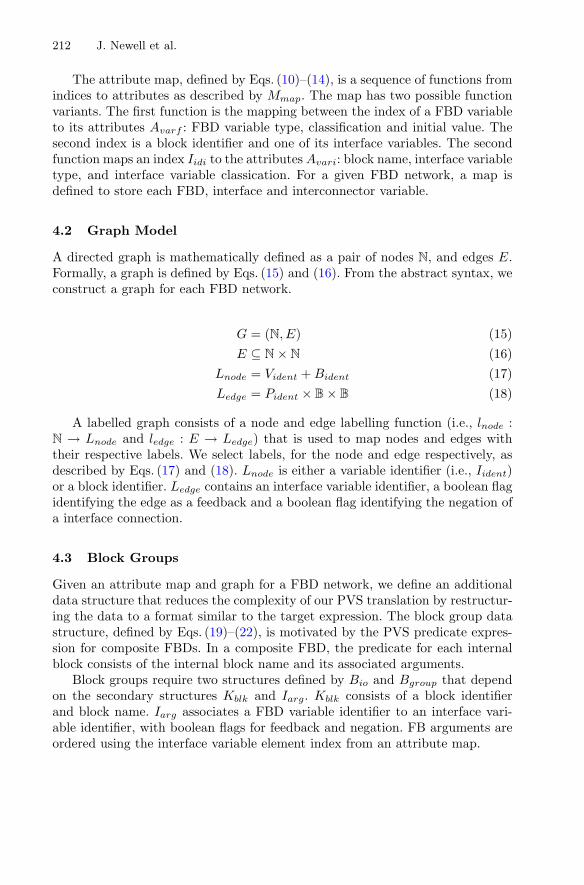
The attribute map, defined by Eqs. (10)–(14), is a sequence of functions fromindices to attributes as described by Mmap. The map has two possible functionvariants. The first function is the mapping between the index of a FBD variableto its attributes Avarf : FBD variable type, classification and initial value. Thesecond index is a block identifier and one of its interface variables. The secondfunction maps an index Iidi to the attributes Avari: block name, interface variabletype, and interface variable classication. For a given FBD network, a map isdefined to store each FBD, interface and interconnector variable.
4.2 Graph Model
A directed graph is mathematically defined as a pair of nodes N, and edges E.Formally, a graph is defined by Eqs. (15) and (16). From the abstract syntax, weconstruct a graph for each FBD network.
G = (N, E) (15)E ⊆ N × N (16)
Lnode = Vident + Bident (17)Ledge = Pident × B × B (18)
A labelled graph consists of a node and edge labelling function (i.e., lnode :N → Lnode and ledge : E → Ledge) that is used to map nodes and edges withtheir respective labels. We select labels, for the node and edge respectively, asdescribed by Eqs. (17) and (18). Lnode is either a variable identifier (i.e., Iident)or a block identifier. Ledge contains an interface variable identifier, a boolean flagidentifying the edge as a feedback and a boolean flag identifying the negation ofa interface connection.
4.3 Block Groups
Given an attribute map and graph for a FBD network, we define an additionaldata structure that reduces the complexity of our PVS translation by restructur-ing the data to a format similar to the target expression. The block group datastructure, defined by Eqs. (19)–(22), is motivated by the PVS predicate expres-sion for composite FBDs. In a composite FBD, the predicate for each internalblock consists of the internal block name and its associated arguments.
Block groups require two structures defined by Bio and Bgroup that dependon the secondary structures Kblk and Iarg. Kblk consists of a block identifierand block name. Iarg associates a FBD variable identifier to an interface vari-able identifier, with boolean flags for feedback and negation. FB arguments areordered using the interface variable element index from an attribute map.
Formal Translation of IEC 61131-3 Function Block Diagrams to PVS 213
Kblk = Bident × Hident (19)Iarg = Vident × Iident × B × B (20)Bio = Kblk × Iarg (21)
Bgroup = Kblk × 〈Iarg〉 (22)fio : Mmap → G → N → {Bio} (23)
fgroup : Mmap → {Bio} → 〈Bgroup〉 (24)
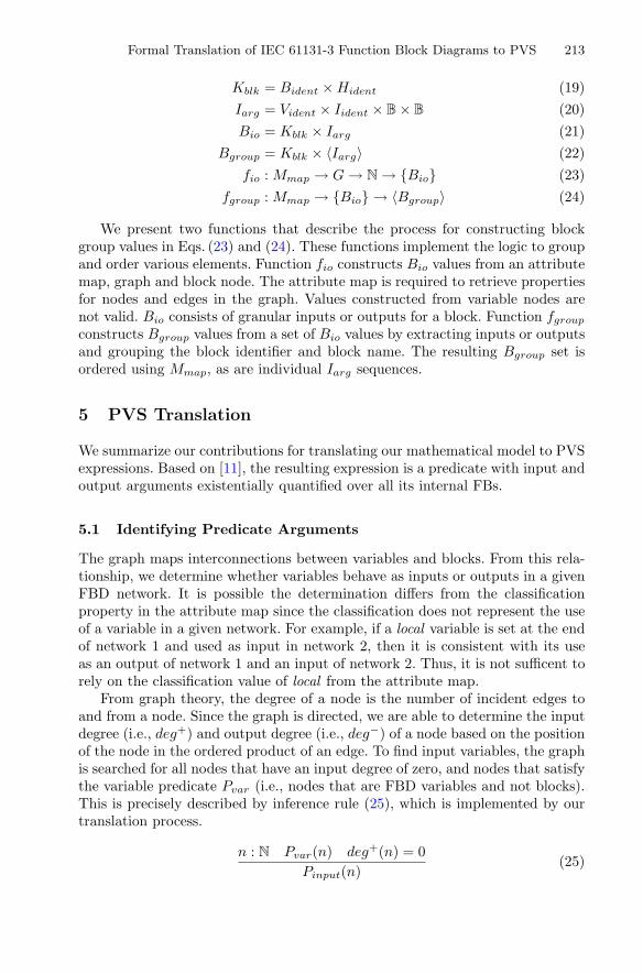
We present two functions that describe the process for constructing blockgroup values in Eqs. (23) and (24). These functions implement the logic to groupand order various elements. Function fio constructs Bio values from an attributemap, graph and block node. The attribute map is required to retrieve propertiesfor nodes and edges in the graph. Values constructed from variable nodes arenot valid. Bio consists of granular inputs or outputs for a block. Function fgroupconstructs Bgroup values from a set of Bio values by extracting inputs or outputsand grouping the block identifier and block name. The resulting Bgroup set isordered using Mmap, as are individual Iarg sequences.
5 PVS Translation
We summarize our contributions for translating our mathematical model to PVSexpressions. Based on [11], the resulting expression is a predicate with input andoutput arguments existentially quantified over all its internal FBs.
5.1 Identifying Predicate Arguments
The graph maps interconnections between variables and blocks. From this rela-tionship, we determine whether variables behave as inputs or outputs in a givenFBD network. It is possible the determination differs from the classificationproperty in the attribute map since the classification does not represent the useof a variable in a given network. For example, if a local variable is set at the endof network 1 and used as input in network 2, then it is consistent with its useas an output of network 1 and an input of network 2. Thus, it is not sufficent torely on the classification value of local from the attribute map.
From graph theory, the degree of a node is the number of incident edges toand from a node. Since the graph is directed, we are able to determine the inputdegree (i.e., deg+) and output degree (i.e., deg−) of a node based on the positionof the node in the ordered product of an edge. To find input variables, the graphis searched for all nodes that have an input degree of zero, and nodes that satisfythe variable predicate Pvar (i.e., nodes that are FBD variables and not blocks).This is precisely described by inference rule (25), which is implemented by ourtranslation process.
n : N Pvar(n) deg+(n) = 0Pinput(n)
(25)
214 J. Newell et al.
∀(e : E) : ¬Pfback(e) n : N Pvar(n) deg−(n) = 0Poutput(n)
(26)
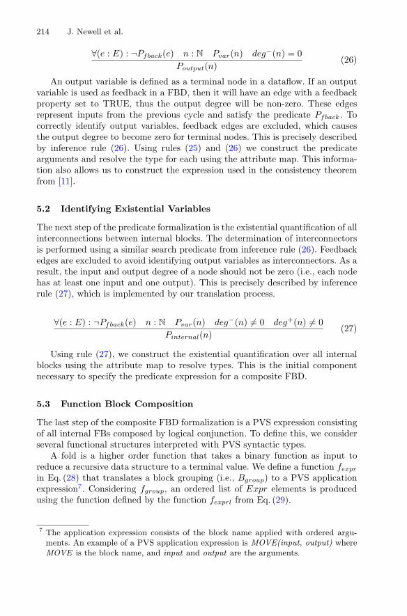
An output variable is defined as a terminal node in a dataflow. If an outputvariable is used as feedback in a FBD, then it will have an edge with a feedbackproperty set to TRUE, thus the output degree will be non-zero. These edgesrepresent inputs from the previous cycle and satisfy the predicate Pfback. Tocorrectly identify output variables, feedback edges are excluded, which causesthe output degree to become zero for terminal nodes. This is precisely describedby inference rule (26). Using rules (25) and (26) we construct the predicatearguments and resolve the type for each using the attribute map. This informa-tion also allows us to construct the expression used in the consistency theoremfrom [11].
5.2 Identifying Existential Variables
The next step of the predicate formalization is the existential quantification of allinterconnections between internal blocks. The determination of interconnectorsis performed using a similar search predicate from inference rule (26). Feedbackedges are excluded to avoid identifying output variables as interconnectors. As aresult, the input and output degree of a node should not be zero (i.e., each nodehas at least one input and one output). This is precisely described by inferencerule (27), which is implemented by our translation process.
∀(e : E) : ¬Pfback(e) n : N Pvar(n) deg−(n) �= 0 deg+(n) �= 0Pinternal(n)
(27)
Using rule (27), we construct the existential quantification over all internalblocks using the attribute map to resolve types. This is the initial componentnecessary to specify the predicate expression for a composite FBD.
5.3 Function Block Composition
The last step of the composite FBD formalization is a PVS expression consistingof all internal FBs composed by logical conjunction. To define this, we considerseveral functional structures interpreted with PVS syntactic types.
A fold is a higher order function that takes a binary function as input toreduce a recursive data structure to a terminal value. We define a function fexprin Eq. (28) that translates a block grouping (i.e., Bgroup) to a PVS applicationexpression7. Considering fgroup, an ordered list of Expr elements is producedusing the function defined by the function fexprl from Eq. (29).
7 The application expression consists of the block name applied with ordered argu-ments. An example of a PVS application expression is MOVE(input, output) whereMOVE is the block name, and input and output are the arguments.
Formal Translation of IEC 61131-3 Function Block Diagrams to PVS 215
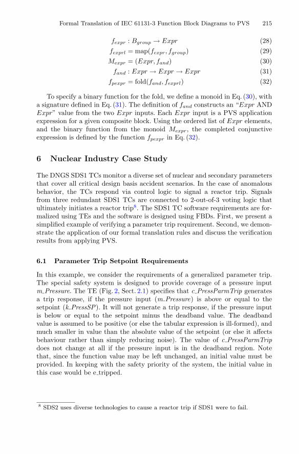
fexpr : Bgroup → Expr (28)fexprl = map(fexpr, fgroup) (29)Mexpr = (Expr, fand) (30)
fand : Expr → Expr → Expr (31)fpexpr = fold(fand, fexprl) (32)
To specify a binary function for the fold, we define a monoid in Eq. (30), witha signature defined in Eq. (31). The definition of fand constructs an “Expr ANDExpr” value from the two Expr inputs. Each Expr input is a PVS applicationexpression for a given composite block. Using the ordered list of Expr elements,and the binary function from the monoid Mexpr, the completed conjunctiveexpression is defined by the function fpexpr in Eq. (32).
6 Nuclear Industry Case Study
The DNGS SDS1 TCs monitor a diverse set of nuclear and secondary parametersthat cover all critical design basis accident scenarios. In the case of anomalousbehavior, the TCs respond via control logic to signal a reactor trip. Signalsfrom three redundant SDS1 TCs are connected to 2-out-of-3 voting logic thatultimately initiates a reactor trip8. The SDS1 TC software requirements are for-malized using TEs and the software is designed using FBDs. First, we present asimplified example of verifying a parameter trip requirement. Second, we demon-strate the application of our formal translation rules and discuss the verificationresults from applying PVS.
6.1 Parameter Trip Setpoint Requirements
In this example, we consider the requirements of a generalized parameter trip.The special safety system is designed to provide coverage of a pressure inputm Pressure. The TE (Fig. 2, Sect. 2.1) specifies that c PressParmTrip generatesa trip response, if the pressure input (m Pressure) is above or equal to thesetpoint (k PressSP). It will not generate a trip response, if the pressure inputis below or equal to the setpoint minus the deadband value. The deadbandvalue is assumed to be positive (or else the tabular expression is ill-formed), andmuch smaller in value than the absolute value of the setpoint (or else it affectsbehaviour rather than simply reducing noise). The value of c PressParmTripdoes not change at all if the pressure input is in the deadband region. Notethat, since the function value may be left unchanged, an initial value must beprovided. In keeping with the safety priority of the system, the initial value inthis case would be e tripped.
8 SDS2 uses diverse technologies to cause a reactor trip if SDS1 were to fail.
216 J. Newell et al.
6.2 Design and Formal Translation
An example design (Fig. 3, Sect. 2.2) uses several built-in IEC 61131-3 FBs tospecify the functional behaviour and uses a feedback connection for the hys-teresis effect. It is important to note that the target PLC treats “de-energised”(“FALSE” = 0) as the safe state, therefore c PressParmTrip = FALSE is equiv-alent to c PressParmTrip = e tripped.
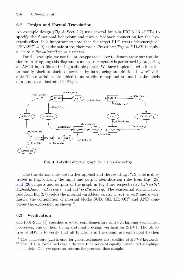
For this example, we use the prototype translator to demonstrate our transla-tion rules. Mapping this diagram to an abstract syntax is performed by preparingan ASCII input file and using a simple parser. We have implemented a functionto modify block-to-block connections by introducing an additional “wire” vari-able. These variables are added to an attribute map and are used in the labelsof a graph, as illustrated in Fig. 4.
Fig. 4. Labelled directed graph for c PressParmTrip
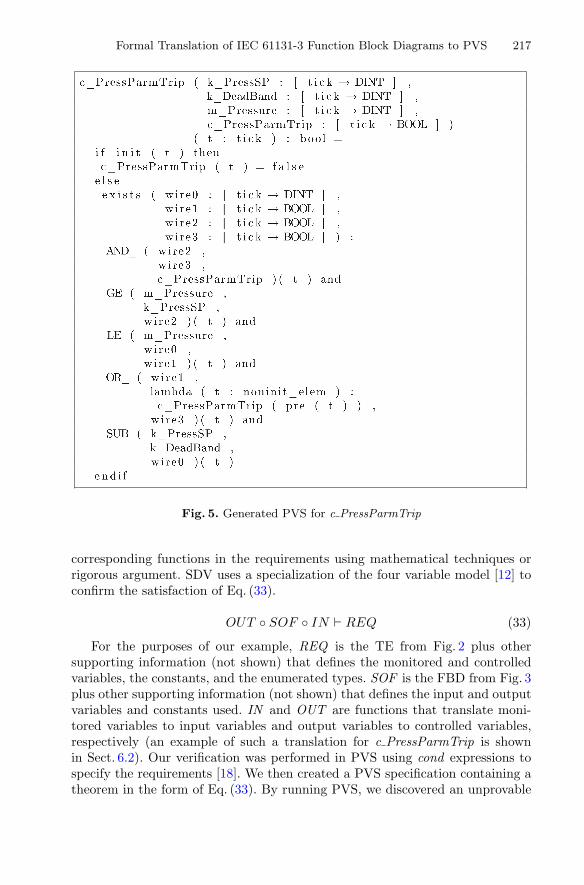
The translation rules are further applied and the resulting PVS code is illus-trated in Fig. 5. Using the input and output identification rules from Eqs. (25)and (26), inputs and outputs of the graph in Fig. 4 are respectively: k PressSP,k DeadBand, m Pressure, and c PressParmTrip. The existential identificationrule from Eq. (27) yields the internal variables: wire 0, wire 1, wire 2, and wire 4.Lastly, the conjunction of internal blocks SUB, GE, LE, OR9 and AND com-pletes the expression as shown10.
6.3 Verification
CE-1001-STD [7] specifies a set of complementary and overlapping verificationprocesses, one of them being systematic design verification (SDV). The objec-tive of SDV is to verify that all functions in the design are equivalent to their9 The underscore (... ) is used for generated names that conflict with PVS keywords.
10 The FBD is formalized over a discrete time series of equally distributed samplings,i.e., ticks. The pre operator returns the previous time sample.
Formal Translation of IEC 61131-3 Function Block Diagrams to PVS 217
Fig. 5. Generated PVS for c PressParmTrip
corresponding functions in the requirements using mathematical techniques orrigorous argument. SDV uses a specialization of the four variable model [12] toconfirm the satisfaction of Eq. (33).
OUT ◦ SOF ◦ IN REQ (33)
For the purposes of our example, REQ is the TE from Fig. 2 plus othersupporting information (not shown) that defines the monitored and controlledvariables, the constants, and the enumerated types. SOF is the FBD from Fig. 3plus other supporting information (not shown) that defines the input and outputvariables and constants used. IN and OUT are functions that translate moni-tored variables to input variables and output variables to controlled variables,respectively (an example of such a translation for c PressParmTrip is shownin Sect. 6.2). Our verification was performed in PVS using cond expressions tospecify the requirements [18]. We then created a PVS specification containing atheorem in the form of Eq. (33). By running PVS, we discovered an unprovable
218 J. Newell et al.
sequent that prevented us from discharging the proof. Upon investigation, werecognize the design failed to add a negation to the first input of the ANDblock. This is a clear demonstration of how formal verification detects subtledesign flaws that could potentially result in unintended behaviour.
The application of the approach11 for SDV on the DNGS SDS1 TC replace-ment project helped identify design pattern inconsistencies that led to animproved FBD-based design approach, uncovered inconsistencies in TEs thatled to a more precise requirements specification, and identified an omitted con-version in the FBD for performing an average power calculation. PVS was used toverify all FBDs in the design, which accounted for 80 % of the overall SDV effort.Our approach was used to automatically discharge 70 % of the proof obligations.The most complicated FBD, a module with 20 FBs and 39 variables, and mod-ules with real-time properties, required user interaction with PVS to dischargethe proof.
7 Related Work
IEC 61131-3 provides definitions for five PLC languages12 and various researchwork has produced formalization and verification of PLC programs. In terms ofthe formal verification of PLC programs written in these languages, there aretypically two main approaches to prove or disprove the correctness of a designwith respect to a certain formal requirements specification or required property:model checking and theorem proving.
In the case of model checking, [8] provides the formal verification of a safetyprocedure in a nuclear power plant (NPP) in which a verified Coloured PetriNet (CPN) model is derived by reinterpretation from the FBD description. [15]transforms FBD descriptions to its logically equivalent Uppaal models that per-form the verification of safety applications in the industrial automation domain.[5] translates ST and FBD into a synchronized data-flow language SIGNAL tocompile and reason about the verification of specifications. In the case of theoremproving, [3] uses Coq to check the correctness of SFC programs, which is auto-matically generated from a graphical front-end. [16] formalizes PLC programsusing higher-order logic and uses HOL to discharge safety properties. Also, [14]presents an algebraic approach to verify PLC programs.
In the case of model checking, there is difficulty scaling up to industrial-sizeapplications. In theorem proving, complex formalisms can be handled, but theprocess of proofs is not fully automated and adds additional overhead to indus-trial scale applications. Thus, the strengths and weaknesses for model checkingand theorem proving are complementary. To balance this issue, our techniquehas been successfully used in an on-going nuclear industrial application, and it is
11 The approach was qualified using a combination of trial use, inspection and accep-tance testing.
12 Function block diagram (FBD), structured text (ST), instruction list (IL), ladderdiagram (LD) and sequential function chart (SFC).

Formal Translation of IEC 61131-3 Function Block Diagrams to PVS 219
novel in that: (1) we translate a FBD design to a formal PVS model; and (2) theresulting PVS model can be verified against TE-based requirements input toPVS.
8 Conclusion and Future Work
In this paper, we have extended the work presented in [10] with an industrial-scaled methodology for the systematic translation of FBD designs compliantwith IEC 61131-3 into the PVS formal specification language. The approachwas developed for OPG and is in current use as part of the verification of theDNGS SDS1 TCs. In combination with PVS, this work has proven effective inuncovering subtle inconsistencies in applying design patterns, inconsistencies inthe requirements documented using TEs, and non-conformance between a FBDdesign and its requirements.
As on-going and future work, we first aim to improve our translation rulesusing PVS to provide more precision for potential tool designers. Secondly, weare currently formalizing proof scripts to increase the level of automation, whichhas potential application in other industrial domains, e.g., aerospace. Lastly,we plan to extend our formalization technique to other IEC 61131-3 compliantprogramming languages, e.g., Structured Text (ST).
Acknowledgements. We would like to thank OPG for their permitting us to describethe work related to the DNGS TC replacement project. The methodology and toolsdescribed herein are the property of OPG. Particularly we thank Ivan Dimitrov, SectionManager, Safety Related Computers, Computers and Control Design, and Mike Viola,SDS Replacement Project Manager, for their valued oversight and assistance. We wouldalso like to thank Lucian Patcas for his thorough review.
References
1. IEEE 7–4.3.2: Standard for Digital Computers in Safety Systems of Nuclear PowerGenerating Stations (Revision of IEEE Std 7–4.3.2-2003). The Institute of Electri-cal and Electronics Engineers (IEEE) (2010)
2. DO-178C: Software Considerations in Airborne Systems and Equipment Certifica-tion. Special Committee 205 of RTCA (2011)
3. Blech, J.O., Biha, S.O.: On formal reasoning on the semantics of PLC using Coq.CoRR abs/1301.3047 (2013)
4. IEC: 61131–3 Ed. 3.0 en: 2013: Programmable Controllers – Part 3: ProgrammingLanguages. International Electrotechnical Commission (2013)
5. Jimenez-Fraustro, F., Rutten, E.: A synchronous model of IEC 61131 PLC lan-guages in SIGNAL. In: Euromicro Conference On Real-Time Systems, pp. 135–142(2001)
6. Jin, Y., Parnas, D.L.: Defining the meaning of tabular mathematical expressions.Sci. Comput. Program. 75(11), 980–1000 (2010)
220 J. Newell et al.
7. Joannou, P., Harauz, J., Viola, M., Cirjanic, R., Chan, D., Whittall, R., Tremaine,D., Moum, G.: Standard for Software Engineering of Safety Critical Software.CANDU Computer Systems Engineering Centre of Excellence Standard CE-1001-STD Rev. 3 (2014)
8. Nemeth, E., Bartha, T.: Formal verification of safety functions by reinterpretationof functional block based specifications. In: Cofer, D., Fantechi, A. (eds.) FMICS2008. LNCS, vol. 5596, pp. 199–214. Springer, Heidelberg (2009)
9. Owre, S., Rushby, J.M., Shankar, N.: PVS: A prototype verification system. In:Kapur, D. (ed.) CADE 1992. LNCS, vol. 607, pp. 748–752. Springer, Heidelberg(1992)
10. Pang, L.: An Engineering Methodology for the Formal Verification of FunctionBlock Based Systems. Ph.D. thesis. McMaster University, Department of Comput-ing and Software (2015)
11. Pang, L., Wang, C., Lawford, M., Wassyng, A.: Formal verification of functionblocks applied to IEC 61131–3. Sci. Comput. Program. 113, 149–190 (2015)
12. Parnas, D.L., Madey, J.: Functional documents for computer systems. Sci. Comput.Program. 25(1), 41–61 (1995)
13. Parnas, D.L., Madey, J., Iglewski, M.: Precise documentation of well-structuredprograms. IEEE Trans. Software Eng. 20, 948–976 (1994)
14. Roussel, J.M., Faure, J.: An algebraic approach for PLC programs verification. In:6th International Workshop on Discrete Event Systems, pp. 303–308 (2002)
15. Soliman, D., Thramboulidis, K., Frey, G.: Transformation of function block dia-grams to Uppaal timed automata for the verification of safety applications. Annu.Rev. Control 36, 338–345 (2012)
16. Volker, N., Kramer, B.J.: Automated verification of function block-based industrialcontrol systems. Sci. Comput. Program. 42(1), 101–113 (2002)
17. Wassyng, A., Janicki, R.: Tabular expressions in software engineering. In: Interna-tional Conference on Software & System Engineering and their Applications, vol.4, pp. 1–46 (2003)
18. Wassyng, A., Lawford, M.: Lessons learned from a successful implementation offormal methods in an industrial project. In: Araki, K., Gnesi, S., Mandrioli, D.(eds.) FME 2003. LNCS, vol. 2805, pp. 133–153. Springer, Heidelberg (2003)