forging solutions design engineering information from … · forging solutions design engineering...
TRANSCRIPT

FORGING SOLUTIONS
Design Engineering Information From FIA
ROLLED RING – ARTICLES
TABLE OF CONTENTS
Forged Grain Flow Boosts Fatigue Life
Structural Integrity Extends Design Limits of Forged Parts
Ten Ways that Forgings Help to Reduce Costs
Improved Alloys Boost Quality and Economy of Forged Components
Value-added Forgings Offer Design Options for Ready-to-Install Parts
Forging Size Plus Shape Capability Expands Metal Design Options
The Best Answer to the Cost/Performance Question
Continuous Improvement Helps Forgings Deliver Optimum Quality
Co-Engineered Forgings
Forgings Superior to Castings Due to Long-term Performance
Forged Rings: The Ultimate in Integrity and Properties
Forging Fundamentals: The Key to Optimum Design Practice
Design for Forgings-Specifications Help
The Language of Forging: Key Terms and Definitions

FORGED GRAIN FLOW BOOSTS FATIGUE LIFEGreatly improved fatigue life and impact strength in aerospace, automotive and other industrial applications, alongwith higher strength in thinner sections (which directly results in lighter parts), are the reasons why emphasis isplaced on optimizing grain flow in forged components.
Orienting the grain structure can enhance mechanical prop-erties, boosting service life several times.This provides one ofthe intrinsic benefits of forgings. Typical examples of thesebenefits include:
• Six to ten times greater impact fatigue life in preci-sion-forged straight bevel gears and 100% to 300% betterfatigue life in near-net-shape spiral bevel gears add up tolonger lasting drive-train components in heavy trucks,construction, marine and agricultural equipment, as com-pared to standard “cut” steel gears. Optimum grain flowpatterns in forged, net teeth make these performanceincreases possible.
• Higher strength in reduced cross-sections is achieved in forged truck and passenger car wheels, becausecontrolled grain flow in the flange area puts the strength where it is needed.When compared to cast wheels,forged wheels save material, cut weight, and more easily meet mileage requirements.
• Improved performance and cost effectiveness are routinely achieved in structural aircraft and aerospacecomponents, including many with large plan-view areas. Control of grain flow in precision aluminum forgingsmakes components stronger in several directions, permitting weight savings and facilitating part consolidation.Extensive labor savings are a major benefit over weldments and built-up composite structures.
Pushing performanceOrientation of grain flow-alignment of the metal microstructure with the geometry of the part being forged-isdirectly responsible for developing maximum tensile strength, toughness (impact strength), fatigue resistance and,ultimately, the greater service-life expectancy that is characteristic of forged net-shaped parts.
No other metalworking components (including castings, machined bars and plates, weldments, and other fabricat-ed assemblies) permit this degree of grain control and subsequent property enhancement. In castings, grain flowcannot be optimized since grain direction is characteristically random as a result of the solidification process.Similarly, machined components exhibit discontinuous grain flow. Because of extensive metal removal, grains arebroken at the part surface, and the surface is where facture usually initiates.At best, grain orientation in machinedparts is unidirectional, taking on the prior patterns of the original bar, billet, or plate.
Continued1
Etched surface of sectioned crankshaft reveals "classic" grain flow pattern that gives forged partstheir strength.
Design Engineering Information From FIA
FORGINGSOLUTIONS
Addressing these processes:
Impression Die
Open Die
Rolled Ring
Cold

“Classical” grain flow follows the contour of a forged part, as is characteristic of a forged crankshaft. However, cer-tain geometries and performance requirements may benefit from a different type of grain flow. For example, cir-cumferential-type hoop strength or strength in the axial direction may be needed, depending on the part geometryand stresses that the part will see in service.What can be accomplished in terms of grain flow is also dependenton the forging techniques and tooling utilized, both of which can affect cost as well as ultimate part performance.
In rib- and web-type forgings, longitudinal grain flow (the strongest orientation in terms of properties) coincideswith the primary grain direction of the starting billet.This initial orientation is created by deformation duringstock fabrication, which typically elongates the grains in a direction parallel to the primary working direction.Further working by closed-die forging modifies and refines the starting-billet grain structure to produce the bestcombination of properties in all test directions.
In most forgings, the initial grain flow direction (longitudinal and the strongest) is oriented within the part alongthe axis that will see the highest in-service loads. However, grain-flow modifications made by judicious use of tool-ing and forging techniques can be utilized to max-imize strength in other directions without sacrific-ing properties along the principal direction.
Grain-flow sensitivitySome metals and alloys exhibit a “grain-flow sensi-tivity,”which is reflected by the degree of isotropyof the material being forged. Materials with highgrain-flow sensitivity exhibit greater differences inproperties between the longitudinal and transversegrain-flow directions. (This does not imply thatforgings are strong in only one direction, since testsshow that properties in any direction usuallyexceed those of non-wrought products, like cast-ings.) The table below lists various metals accordingto their grain-flow sensitivity.
Grain-flow patterns can be con-trolled to a far greater extent in alu-minum and other alloy precisionforgings than in parts conventional-ly forged between two-piece upperand lower dies, due to the use ofmulti-segment dies.This type oftooling is standard for aluminumand some other alloy precisionparts, and it creates controlledpaths for the material to flow intoseveral regions of the die cavity orinto gutter areas surrounding thecavity.As with conventional forg-ings, additional modifications tograin direction can be achieved bythe use of bending or preformingdies prior to blocking and finishing.
Continued
Grain flow that follows the contour of forged teeth in steel bevelgears is directly responsible for improvements in fatigue life overmachined gears.
2
CONTINUED
Grain-flow sensitivity is a function of materialDepending on the type of metal or alloy and its microstructural characteristics, grain-flow sensitivity - reflected in the degree ofanisotropy or property directionality - can vary widely. This dependenceshould be taken into account in forging design.Least sensitivePure metals: aluminum, nickel, cobalt, silver and copper.Solid-state alloys: nickel/copper and aluminum/copper alloys.Moderate sensitivityPrecipitation-hardenable alloys: 300 series stainless steels, magnesiumalloys, and nickel/chromium alloys.Steels: carbon and alloy; 400 Series stainless.High sensitivityTwo-phase alloys: Most high-strength aluminum alloys, 2014, 7075, 7079,etc.; many nickel and cobalt-based superalloys including INCO 718,Waspalloy and Astroloy.Two-phase alloys (not fully recrystallized):Titanium alloys like Ti-6Al-4V;certain alloys of zirconium, molybdenum alloys like Mo-Ti-Zr.
FORGING SOLUTIONS
Two-way streetProper development of grain-flow patterns, along with the ultimateproperty profile, can only be achieved by good communicationbetween the design engineer and the forger. It is this two-way com-munication that facilitates a truly effective cost/performance balance.
Key to this balance is specifying grain-flow requirements only wherethey are absolutely necessary. In practice, only a few areas of a forgingrequire optimum grain flow, and most non-critical areas are subject toconsiderably lower stresses. Highly stressed areas (aptly named“hotspots”) can readily be identified by determining the failure mode.
Such analysis helps to avoid over-specifying grain flow, whichincrease costs. In many cases, optimum grain flow (hence, optimumproperties for a particular component) is achieved by employing oneor more clocker dies, and then finish dies. Conversely, multiple dies cannot improve the grain flow of some designs,and specifying a blocker operation merely increases the tooling cost. It always pays to discuss final component applica-tion with the forger in order to determine how best to optimize grain flow while simultaneously keeping tooling andproduction costs down.
FORGING INDUSTRY ASSOCIATION25 West Prospect Ave., Suite 300, Cleveland, OH 44115Phone: 216-781-6260 Fax: 216-781-0102 E-mail: [email protected] Website: www.forging.org
© Copyright 2007, Forging Industry Association
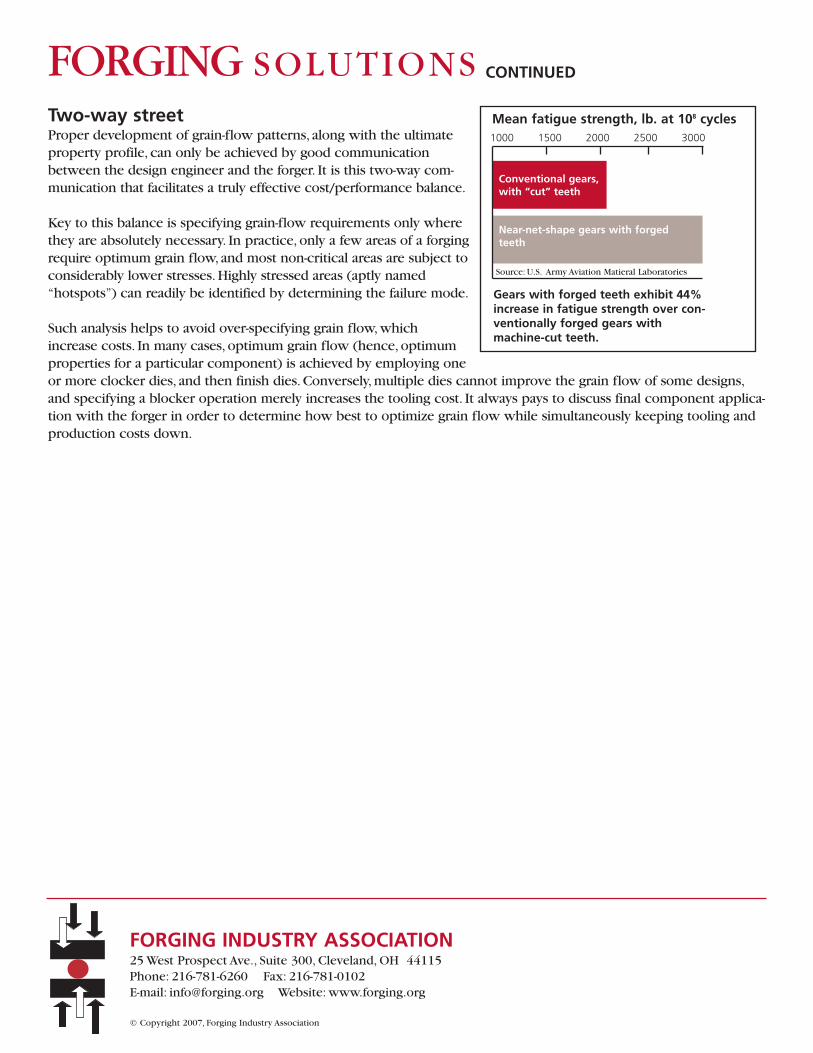
Mean fatigue strength, lb. at 108 cycles1000 1500 2000 2500 3000
Conventional gears,with “cut” teeth
Near-net-shape gears with forgedteeth
Source: U.S. Army Aviation Matieral Laboratories
Gears with forged teeth exhibit 44%increase in fatigue strength over con-ventionally forged gears with machine-cut teeth.
CONTINUEDFORGING SOLUTIONS

STRUCTURAL INTEGRITY EXTENDS DESIGNLIMITS OF FORGED PARTSDesign engineers routinely find they cantake greater advantage of the ultimateproperty values of forgings, as compared tometal components fabricated by otherprocesses.This means that forgings can belighter and smaller. Depending on the appli-cation, designs for forged components canbe based on 75 to 80% of the yieldstrength, for instance. Not surprisingly, thisdesign percentage is considerably lower forcastings.
A specific example is the use of forgingswith a high tensile strength in industrialdryers and rotary kilns, permitting the useof design limits that are 36% higher thancastings. Similarly, forged gears can bedesigned to withstand higher stresses.Structural integrity, overall quality, higherstrength, and the consistent properties offorgings place them above castings andcomponents produced by other metalwork-ing processes.The inherent soundness offorged components is reflected in theirstructural, metallurgical, and dimensionalcharacteristics. Consequently, where metalcomponents are concerned, forgings are the first choice for many applications, ranging from high-speed gears to criti-cal aerospace components.
Reliability via strength
When it comes to strength, the reputation that forgings possess is well deserved. Significantly higher property valuesfor forged versus cast steel are dramatically depicted in the bar chart above.Through the reduction achieved in theforging process and the accompanying homogeneous microstructure, forged components consistently attain higherstrength levels than castings and metal parts made by other methods. Even when transverse properties are increasedto equal longitudinal property values via an upsetting operation prior to conventional forging, tensile properties andfatigue limits surpass those of competitive fabrication methods. Similarly, the corresponding toughness and ductility
Continued
1
Hot-work reduction, as is characteristic of hot forging, produces significantmechanical property improvements versus as cast steels. Data are forquenched and tempered 4140 steel.
Design Engineering Information From FIA
FORGINGSOLUTIONS
Addressing these processes:
Impression Die
Open Die
Rolled Ring
Cold
RELATIVE PROPERTY VALUE, % (as-cast = 100)
TRUE STRESS AT FAILURE
75 100 125 150 200
REDUCTION INAREA
ABSORBEDENERGY,CHARPYV-NOTCH TESTS
As-cast
4:1 reduction
10:1 reduction
As-cast
4:1 reduction
10:1 reduction
As-cast
4:1 reduction
10:1 reduction
Source: Philip Bruce Rittgers, Master of Science Thesis,1987, Colorado School of Mines.
achievable in forging surpass all other metalworkingprocesses.
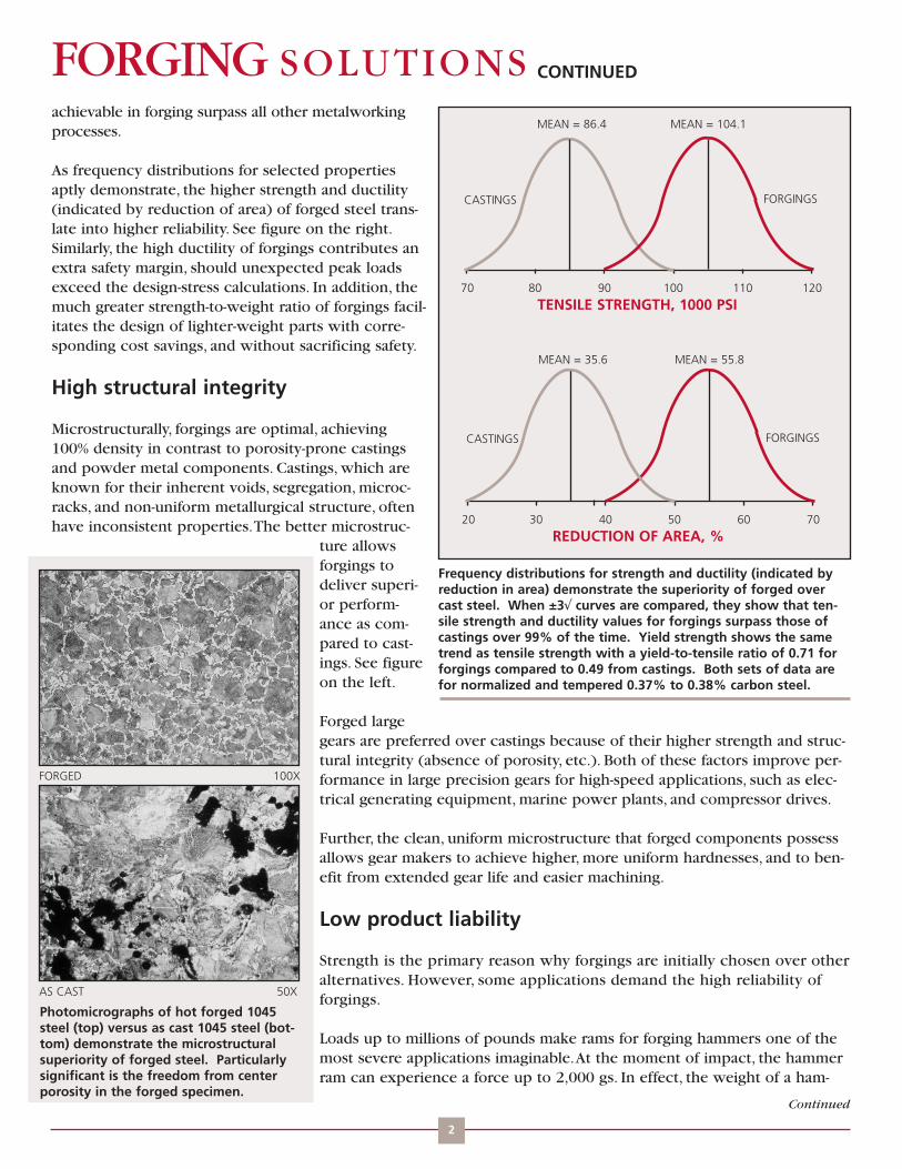
As frequency distributions for selected propertiesaptly demonstrate, the higher strength and ductility(indicated by reduction of area) of forged steel trans-late into higher reliability. See figure on the right.Similarly, the high ductility of forgings contributes anextra safety margin, should unexpected peak loadsexceed the design-stress calculations. In addition, themuch greater strength-to-weight ratio of forgings facil-itates the design of lighter-weight parts with corre-sponding cost savings, and without sacrificing safety.
High structural integrity
Microstructurally, forgings are optimal, achieving100% density in contrast to porosity-prone castingsand powder metal components. Castings, which areknown for their inherent voids, segregation, microc-racks, and non-uniform metallurgical structure, oftenhave inconsistent properties.The better microstruc-
ture allowsforgings todeliver superi-or perform-ance as com-pared to cast-ings. See figureon the left.
Forged largegears are preferred over castings because of their higher strength and struc-tural integrity (absence of porosity, etc.). Both of these factors improve per-formance in large precision gears for high-speed applications, such as elec-trical generating equipment, marine power plants, and compressor drives.
Further, the clean, uniform microstructure that forged components possessallows gear makers to achieve higher, more uniform hardnesses, and to ben-efit from extended gear life and easier machining.
Low product liability
Strength is the primary reason why forgings are initially chosen over otheralternatives. However, some applications demand the high reliability offorgings.
Loads up to millions of pounds make rams for forging hammers one of themost severe applications imaginable.At the moment of impact, the hammerram can experience a force up to 2,000 gs. In effect, the weight of a ham-
Continued
Frequency distributions for strength and ductility (indicated byreduction in area) demonstrate the superiority of forged overcast steel. When ±3√ curves are compared, they show that ten-sile strength and ductility values for forgings surpass those ofcastings over 99% of the time. Yield strength shows the sametrend as tensile strength with a yield-to-tensile ratio of 0.71 forforgings compared to 0.49 from castings. Both sets of data arefor normalized and tempered 0.37% to 0.38% carbon steel.
2
CONTINUEDFORGING SOLUTIONS
70 80 90 100 110 120
TENSILE STRENGTH, 1000 PSI
20 30 40 50 60 70
REDUCTION OF AREA, %
CASTINGS FORGINGS
CASTINGS FORGINGS
MEAN = 86.4 MEAN = 104.1
MEAN = 35.6 MEAN = 55.8
Photomicrographs of hot forged 1045steel (top) versus as cast 1045 steel (bot-tom) demonstrate the microstructuralsuperiority of forged steel. Particularlysignificant is the freedom from centerporosity in the forged specimen.
FORGED 100X
AS CAST 50X

mer ram (typically ranging from 500 to 50,000 pounds) increases to 2,000 times that at impact.The resulting highstresses make forged rams the clear choice. Stronger and tougher than cast materials, forged 4140 and 4340 steelrams possess significantly higher endurance limits, making them more fatigue-resistant. Because of product liabilityconsiderations, cast rams are not even considered.
A step above machining
Strength-wise, forgings outperform machined components, too. Even though parts machined from bar stockmay not suffer from the effects of voids and inclusions, they still do not possess the integral strength of forg-ings, because the grain flow is interrupted at machined surfaces. In many instances, unusual shapes like a pro-peller nut can be forged “near-net” with the added benefit of cost savings due to reduced machining.Typically,conversion from machining to near-net shape forging (with its increased strength) boosts service life dramati-cally. In a number of cases, precision forging not only increases part life significantly, but causes manufacturingcosts to drop, as well.
Forged quality means less testing
Reduced testing is another important benefit derived directly from the integrity of forgings.The extreme strainrates generated during forging immediately identify the presence of defective raw material so that forgings are vir-tually “self-testing.” Because of the part-to-part uniformity of forgings, manufacturers do not have to ascertain thequality of every incoming component before putting parts through further in-house processing.This benefit isespecially important with outside purchased components that are subsequently machined.While forgings readilylend themselves to quality control sampling plans, many castings need to be 100% tested to ensure their integrity.
FORGING INDUSTRY ASSOCIATION25 West Prospect Ave., Suite 300, Cleveland, OH 44115Phone: 216-781-6260 Fax: 216-781-0102 E-mail: [email protected] Website: www.forging.org
© Copyright 2007, Forging Industry Association
CONTINUEDFORGING SOLUTIONS

TEN WAYS THAT FORGINGS HELP TO REDUCECOSTSWhen properly designed, forgings can be more cost-effectivethan metal parts produced by alternative methods, such ascastings, machined bard and plate, weldments, stampings, built-up structures, sheet metal, and other fabricated assemblies.
Even when forged parts initially cost more than competitivemetal products, a look at life-cycle costs often justifies the useof forgings.
1. Greater strength-to-weight versus castingsHigher strength-to-weight ratios often make forgings competi-tive with castings; not only because of their lighter weight, butalso because forgings outperform castings. Forged connectingrods for automobiles are more than 10% lighter on average,and they are also stronger than cast versions.
2. Eliminating weldmentsSwitching to forgings from multipart weldments also leads tocost reduction by eliminating labor-intensive welding and set-up operations.This approach has been successfully utilized inaircraft engines, where massive integral forgings eliminate elec-tron-beam and inertial welds between adjacent components,and in primary missile structures, where a one-piece cylindri-cal forging with built-in stiffening ribs outperforms a structuralshell made by welding sheet and plate to fabricate internalstiffening rings. See figure on the right.
3. Reduced inspection and testingIn pressure vessel applications, such as steam headers for utilityboilers and catalytic crackers for petrochemical production,forgings do not require periodic inspections like welded parts do.This benefit is particularly important whenwelds are encased in concrete or otherwise difficult, if not impossible, to inspect.
When welds are unavoidable, flanges and other features can be incorporated in forged components to allow easilyaccessible butt welds to be made. In addition, increased section thickness in the boss area will help compensatefor any weakness in the heat-affected zone, when welding is necessary.
Reduced quality control testing can also contribute to cost savings because forgings readily lend themselves toContinued
1
Cost analysis for a nose cowl frame shows that blocker type forgings are 36% cheaper than a sheetmetal/extrusion weldment at 1200 parts. The majorcontributor to the higher cost of the fabrication isassembly labor.
Design Engineering Information From FIA
FORGINGSOLUTIONS
Addressing these processes:
Impression Die
Open Die
Rolled Ring
Cold
0
20%
40%
60%
80%
100%
LABOR ONLY
SHEE
T M
ETA
L/EX
TRU
SIO
N W
ELD
MEN
T
BLC
KER
-TY
PE F
OR
GIN
G
COST IN %(100% = total cost of sheet metal/extrusion weldment)
quality control sampling plans, while 100% of critical castings need to be tested.
4. Replacing assemblies, fabricationsCost savings are usually achieved when forgings replace complex fabrications and assemblies. For example, replac-ing a complex construction from a number of components with a single forging can cut overall manufacturingcosts dramatically.
Cold forging, too, can be more economical than multicomponent assembly. Cold forging can consolidate the func-tionality that might have required multiple pieces plus joining into a single piece.
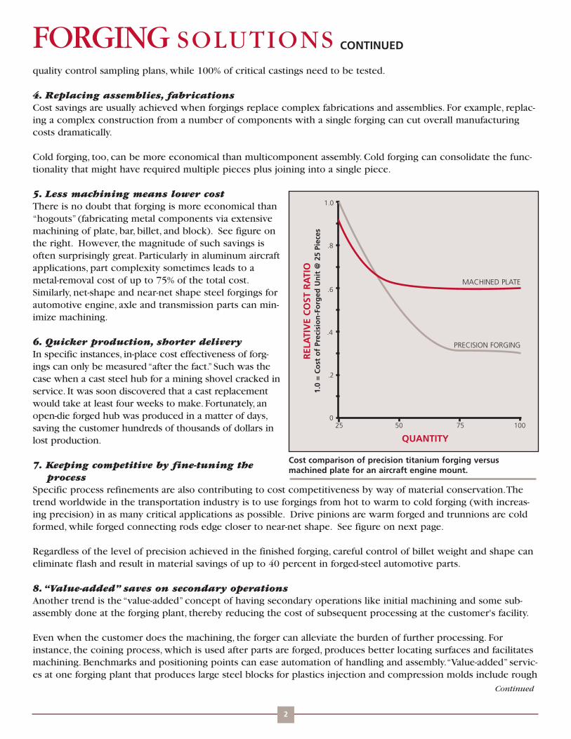
5. Less machining means lower costThere is no doubt that forging is more economical than“hogouts” (fabricating metal components via extensivemachining of plate, bar, billet, and block). See figure onthe right. However, the magnitude of such savings isoften surprisingly great. Particularly in aluminum aircraftapplications, part complexity sometimes leads to ametal-removal cost of up to 75% of the total cost.Similarly, net-shape and near-net shape steel forgings forautomotive engine, axle and transmission parts can min-imize machining.
6. Quicker production, shorter deliveryIn specific instances, in-place cost effectiveness of forg-ings can only be measured “after the fact.” Such was thecase when a cast steel hub for a mining shovel cracked inservice. It was soon discovered that a cast replacementwould take at least four weeks to make. Fortunately, anopen-die forged hub was produced in a matter of days,saving the customer hundreds of thousands of dollars inlost production.
7. Keeping competitive by fine-tuning theprocess
Specific process refinements are also contributing to cost competitiveness by way of material conservation.Thetrend worldwide in the transportation industry is to use forgings from hot to warm to cold forging (with increas-ing precision) in as many critical applications as possible. Drive pinions are warm forged and trunnions are coldformed, while forged connecting rods edge closer to near-net shape. See figure on next page.
Regardless of the level of precision achieved in the finished forging, careful control of billet weight and shape caneliminate flash and result in material savings of up to 40 percent in forged-steel automotive parts.
8.“Value-added” saves on secondary operationsAnother trend is the “value-added” concept of having secondary operations like initial machining and some sub-assembly done at the forging plant, thereby reducing the cost of subsequent processing at the customer's facility.
Even when the customer does the machining, the forger can alleviate the burden of further processing. Forinstance, the coining process, which is used after parts are forged, produces better locating surfaces and facilitatesmachining. Benchmarks and positioning points can ease automation of handling and assembly.“Value-added” servic-es at one forging plant that produces large steel blocks for plastics injection and compression molds include rough
Continued
2
CONTINUEDFORGING SOLUTIONS
0
.2
.4
.6
.8
1.0
QUANTITY
25 50 75 100
REL
ATI
VE
CO
ST R
ATI
O1.
0 =
Co
st o
f Pr
ecis
ion
-Fo
rged
Un
it @
25
Piec
es
MACHINED PLATE
PRECISION FORGING
Cost comparison of precision titanium forging versusmachined plate for an aircraft engine mount.

machining to with 0.5 in. of final dimensions.Consequently, customers realize both significantlylower machining costs and faster overall productiontimes.
9. Materials innovationsLess expensive, easier-to-process materials optionslike microalloyed steels deliver great economies inforged components such as automotive transmissionand engine parts. Conserving energy by eliminatingheat treatment, switching from quenched and tem-pered alloy steels to air-cooled microalloyed grades,saves as much as 15% on connecting rods, crank-shafts, gears, steering arms, and wheel hubs.Also, forg-ings made from continuous cast steel on automaticpresses can be cost-competitive with ductile-ironparts.
10. Design optimizationThere are many conventional ways to cut costs-reduc-ing drafts, tolerances, reviewing process options, sub-stituting lower-cost materials, making property trade-offs, and more-that should be considered to achievethe most cost-effective forging. However, optimizationof a forging design should be all-inclusive for besteconomy.
When outside constraints limit the forging design,choosing another alloy or altering the heat-treatmentpractice can readily meet the increased strengthrequirements. However, with castings, the only recoursewould be a change in design or configuration.
FORGING INDUSTRY ASSOCIATION25 West Prospect Ave., Suite 300, Cleveland, OH 44115Phone: 216-781-6260 Fax: 216-781-0102 E-mail: [email protected] Website: www.forging.org
© Copyright 2007, Forging Industry Association
CONTINUEDFORGING SOLUTIONS
Warm forged automotive drive pinion (left) is produced closerto net shape than a hot forged version (right), saving materialand energy and reducing required machining.

IMPROVED ALLOYS BOOST QUALITY ANDECONOMY OF FORGED COMPONENTSMaterials developments and refine-ments on existing alloys can deliverhigher quality, improved part perform-ance, and significant economies forforged parts versus alternative metalcomponents.At the top of theimproved materials list are microal-loyed steels, strand-cast steels, and tita-nium alloys.
Microalloyed Steels
Microalloyed steels-intermediate car-bon steel alloys (0.3 to 0.6% C) thatincorporate small amounts of vanadi-um, niobium, or other elements-forforging applications offer potentialeconomies, because mechanical prop-erties are achieved “as-forged” via con-trolled cooling. See figure on right.
A myriad of high-strength, forged components have been documented for their overall cost savings.These compo-nents include crankshafts, connecting rods, motorcycle flywheels, truck-wheel spindles, steering knuckles, liftinghooks and related hardware, and railroad coupling cylinders.
Although microalloy forgings have been utilized in Europe, Japan, and elsewhere since the early 1970s, their wide-spread usage in the U.S. was deferred in part because of concerns for adequate toughness and product liability.Things changed with the introduction of “second-generation” lower-carbon-content (0.1 to 0.3% C) microalloyswith improved toughness and “third-generation” (0.15% C) microalloys with toughness up to six times that of earli-er versions.
In fact, the third-generation microalloys with self-tempered martensite microstructures exhibit toughness and impactproperties that equal or exceed those of higher alloys like quenched-and-tempered 4140, while delivering tensilestrengths up to 190 ksi. See next figure. These higher-performance microalloys are targeted for automotive, agricul-tural, truck, and heavy equipment applications, some of which are nearing full production.
Equally significant are microalloyed steels with ferrite-bainite microstructure and low carbon content.They are suit-Continued
1
Microalloyed steel properties are developed in the "as-forged" condition. In contrast to conventional quenched and tempered steels, savings can be gained byelimination of hardening, tempering, and stress-relieving heat treatments.
Design Engineering Information From FIA
FORGINGSOLUTIONS
Addressing these processes:
Impression Die
Open Die
Rolled Ring
Cold
QUENCHED-AND-TEMPERED STEELS
Tem
per
atu
re
MICROALLY STEELS
DIE FORGING
STRESS RELIEVINGTEMPERING
HARDENING
DIE FORGING
CONTROLLED COLLING
STRAIGHTENING
Time

able for a wide range of forging processes, from cold headingthrough conventional hot forging.
With the first-generation microalloyed steels, the Mn-Mo-Nbcomposition achieved a grain size of 5 microns under con-trolled rolling conditions.The toughness of these steels is def-initely impressive: for a water quenched 138-ksi tensilestrength steel, Charpy V-notch toughness exceeds 50 ft-lb atroom temperature. See bottom figure. In addition, these newalloys responded well to surface hardening treatments, whereextra fatigue- or wear-resistant properties are desired.
Faster and better strand-cast materials
Steel suppliers have increased the production of strand-caststeel bar-practically all carbon and low-alloy steel grades-forforged components. Streamlined processing is moving fromcast billet or bloom to forging stock to save both energy (vir-tually no reheating) and processing time (one rolling processversus two), resulting in cost reductions on the forging stock.
Just as important is the improved quality that is routinelyachieved in strand-cast products for forging. Strand cast materials possess good internal structures, due to theincorporation of shrouding and electromagnetic stirring.
Shrouding the teeming stream prevents oxides from forming and produces a much cleaner steel that boostsfatigue performance, It also increases transverse toughness, and facilitates machinability of forged parts. Other ben-efits include forgings with improved surface finishes and highly uniform chemical compositions throughout.
Materials for aerospace/high temperatures
Improved materials expanded the scope for preci-sion forging of aerospace structural components.Although developments in hot-die technology,isothermal forging, and conventional forging tech-niques increased the capability to manufacture titani-um net-shape forgings, alloy developments have alsoplayed a significant role.
For example, alloy Ti 10-2-3, a near-beta alloy, permitsforging at lower temperatures and increases forgeabili-ty over alpha-beta alloys like Ti 6-4.Ti precision forg-ings can be produced with extended plan view areas(PVAs).
The third generation microalloyed steels possess properties equivalent to quenched and tempered carbonand alloy steels in the 35-45 HRC range.
CONTINUEDFORGING SOLUTIONS
TENSILE STRENGTH (1000 psi)
Microalloyed steels with a ferrite bainite microstructure exhibitgood properties as compared to quenched and tempered steels.
TOUGHNESS, CHARPY V-NOTCH (ft-lb)
0 50 100 150 200
THIRD-GENERATION MICROALLOY
4140
0 10 20 30 40
THIRD-GENERATION MICROALLOY
4140
THIRD-GENERATION MICROALLOY
4140
THIRD-GENERATION MICROALLOY
4140 -22OF
+32OF
+86OF
YS TS RA CVN (FT-LB)STEEL/CONDITION (KSI) (KSI) (%) 0OF 75OF
1045/Q&T1 82 123 40 12 20
10V45/HR2 86 125 29 4 12
MA/WQ3 (FERRITE-BAINITE) 114 138 63 33 53
MA/AC4 (FERRITE-BAINITE) 62 97 61 46 68
* BAR FORGING TRIALS (1-IN. THICK DISKS)1. QUENCHED AND TEMPERED. 2. HOT-ROLLED. 3. MICROALLY. 4. MICROALLY, AIR-COOLED.
MECHANICAL PROPERTIES *
FORGING INDUSTRY ASSOCIATION25 West Prospect Ave., Suite 300, Cleveland, OH 44115Phone: 216-781-6260 Fax: 216-781-0102 E-mail: [email protected] Website: www.forging.org
© Copyright 2007, Forging Industry Association

VALUE-ADDED FORGINGS OFFER DESIGNOPTIONS FOR READY-TO-INSTALL PARTSOriginal equipment manufacturers (OEMs) continue to demand morevalue-added services from their suppliers.They realize that their businessshould focus on design and assembly, of automobiles, trucks, planes,heavy equipment, or whatever their end product may be.
OEMs no longer want to support expensive, captive-component manu-facturing operations such as forging, machining, finishing, grinding, andplating. Ideally, they want finished components delivered on a just-in-time(JIT) basis in special containers, pre-tested and ready to assemble.
Many custom forgers have been adding value to their products via heattreating and machining operations. See figures on this page. Forgingcompanies have further augmented their capabilities with finish-machin-ing, painting, plating, testing, and other capital equipment to facilitate thedesign and manufacture of ready-to-install or assemble products.
Value-added forgings aid designers
While many value-addedservices translate directly into production-related economic benefits forthe forging consumer, there are also inherent benefits for the designer.Based on design criteria-stresses the part will undergo, environmentalconditions, service life, and more-designers can rely on the forger'sexpertise in identifying the most efficient and economical forging, heat-treating and finishing operations to produce the optimum part.A case inpoint is a forged slack adjuster that achieves greater levels of reliabilityand cuts production costs, thanks to a forger's redesign.
When a forger produces a finished, value-added forging, the limitations ofin-house capabilities, the need to identify and perform interim processingsteps, and the evaluation of potential secondary suppliers are no longerprimary concerns. In effect, a single forging supplier requires less techni-cal coordination than multiple suppliers or in-house operations.The rangeof services available expands the number of options open to the designer.
Perhaps even more important, the forger can make the designer's job easier by recommending processing changes and ancillary operations that
The crawler track assembly for miningmachine outperformed earlier assemblies ofcast low alloy steel track shoes that broke inservice. The forger redesigned the shoe as ahot forged part that was 4 lb. lighter, assem-bled it with other forged and machined partsand delivered to the complete assembly tothe customer.
Design Engineering Information From FIA
FORGINGSOLUTIONS
Addressing these processes:
Impression Die
Open Die
Rolled Ring
Cold
Continued
1
The forged "tulip" is a critical part for a con-stant velocity joint. It needs to accommodatethe ups and downs of the suspension, theturns of the steering gear and deliver powerto the wheels. The steel part was warmextuded to the finished form except for minor machining and location of specific induc-tion hardening locations.
CONTINUEDFORGING SOLUTIONSin the forger's experience yield a nearer-to-net-shape part. Often,the forger can help come up with subtle design changes, features,or processing refinements that permit a smaller, lighter, or higher-performance forged component to do what otherwise might nothave been possible.
Significant cost savings
Why opt for value-added forgings? Simply put, studies point outthat significant cost and time savings can be realized for justabout any type of forged component. For the forged part con-sumer, fewer secondary operations mean fewer headaches,reduced in-process controls and inspection, less manpower, and asmaller capital investment in equipment. (See Table 1 for addition-al benefits.)
Wide range of value-added services
Adding value to a forged product by performing ancillary opera-tions normally done by the OEM can range from supplying pre-qualified parts (ready to go through further processing, such asmachining ) to fully finished assemblies that incorporate forgingsas the major component. In general, value-added services includejust about any operation or process performed after forging, butare not limited to post-forging capabilities.
Some major value-added services may include:Custom processing results in more dimensionally accurate or closer-to-net shape parts, and it also helps reduce secondary operations. For instance, coining processes produce closer tolerances or better locating surfaces, which reduce a customer's machining operations. Combinations of hot and cold forging or warm forging produce components closer to net shape, eliminating expensive machining operations.
Testing includes destructive and nondestructive (NDT) testing, as well as statistical data analysis for SPC (statistical process control), coordinate measuring machines, and others.
Computerized design/analysis can be used to help design parts to the optimum configuration. CAD/CAM (computer-aided design/manufacturing), flow modeling,AI (artificial intelligence) systems, etc. can expedite accurate designs and shorten production schedules.
Electronic data transfer includes transfer of engineering drawings, CAD data, and CAM data for machining at customers' plants and to conduct entire purchasing transactions-purchase orders, shipping and certification data, delivery dates, quotations, and more.
Heat treating ranges from typical annealing and normalizing to full hardening and tempering, but also includes nitriding, vacuum heat treatments, and special treatments such as strain-aging, precipitation hardening, and double tempering, where deemed necessary for high performance alloys.Target dimensioning puts “targets” (benchmarks or reference points) on a part so that the customer can do subsequent machining without having to re-qualify the part. Coordinate measuring machines and six fixture points are sometimes used, especially for aerospace structural forgings, where up to 75% of the component weight is typically removed.
Machining operations range from rough to finish operations with a specified surface roughness. Drilling holes, cutting threads, surface grinding, center drilling, CNC (computer numerical control) machining, and just about any other metal-removal operation are within the realm of these services.
Continued
2
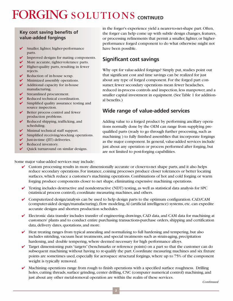
Key cost saving benefits of value-added forgings
Smaller, lighter, higher-performance parts.Improved designs for mating components.More accurate, tighter-tolerance parts.Higher-quality parts, resulting in fewer rejects.Reduction of in-house scrap.Minimized assembly operations.Additional capacity for in-house manufacturing.Streamlined procurement.Reduced technical coordination.Simplified quality assurance testing and source inspection.Better process control and fewer production problems.Reduced shipping, trafficking, and scheduling.Minimal technical staff support.Simplified receiving/stocking operations.Just-in-time (JIT) deliveries.Reduced inventory.Quick turnaround on similar designs.

CONTINUEDFORGING SOLUTIONS
FORGING INDUSTRY ASSOCIATION25 West Prospect Ave., Suite 300, Cleveland, OH 44115Phone: 216-781-6260 Fax: 216-781-0102 E-mail: [email protected] Website: www.forging.org
© Copyright 2007, Forging Industry Association
Finishing operations run the gamut of plating, anodizing, and protective-coating operations, including durable epoxy finishes for subassemblies.
Subassembly work can be performed especially when automated assembly/manufacturing operations can occur due to long-term contracts.
Special requirements, often requested by the customer, are becoming more prevalent.A prime example is the use of special containers, supplied by the customer and designed to facilitate assembly or further processing at the customer's plant.Another forger pre-balances forged wheels to save the customer this burden after delivery.
Teamwork essential
Not surprisingly, taking full advantage of value-added forgings requires open communications.Your forging suppliermust have a firm understanding of design criteria, and accurate final part drawings should be submitted as early aspossible.All component details should be specified, including mating-surface conditions, subassembly work, andpotential options on design features.

FORGING SIZE PLUS SHAPE CAPABILITYEXPANDS METAL DESIGN OPTIONSIt is no design secret thatforgings are often consideredfor their high strength, struc-tural integrity, extra long serv-ice life, unmatched impacttoughness, and other desir-able characteristics. But whatis not usually thought of isthe tremendous design versa-tility, achievable by the widerange of components thatcan be forged with currenttechnology.
Evolutionary developments—among them, key processingrefinements, computerized equipment, and newly developed alloys—permitlarger-size components, more complex configurations, and closer tolerancesto be achieved in most forging processes. Part size has expanded whileshapes approach an ever-increasing degree of part complexity.
With few limitations, virtually any shape imaginable can be forged, or can beeconomically put together with forged components. Shapes range from barswith basic cross sections (round, square, hexagonal) and simple shafts tocomplex, contoured profiles that integrate a thin rib-and web structure andbuilt-in attachment features. Similarly, size capability for all forging processescovers an enormous range, from ounces to more than 150 tons. However,each of the many forging processes has its own special design niche interms of size, shape, part complexity, and material options.
Impression-die (closed-die) forging of steel can produce an almost limitless variety of three-dimensional shapes thatrange in weight from mere ounces up to more than 25 tons. See Figures 1 to 3. Additional flexibility in forming bothsymmetrical and nonsymmetrical shapes comes from preforming and blocking operations (sometimes bending) priorto forging in finisher dies.
Part geometries range from some of the easiest for forge, such as simple spherical shapes, block-like rectangular solids,and disc-like configurations, to the most intricate components with thin and long sections that incorporate thin webs,as well as relatively high vertical projections like ribs and bosses.Accompanying photos dramatically demonstrateforged-shape capability.
Figure 1. Impression die forging has great shape capability.
Design Engineering Information From FIA
FORGINGSOLUTIONS
Addressing these processes:
Impression Die
Open Die
Rolled Ring
Cold
1
Figure 3. Steel valve bodies, press forgedin closed dies.
Figure 2. Impression die forged aluminumwheels.
Continued

CONTINUEDFORGING SOLUTIONS
2
Most engineering metalsand alloy can be forged viaconventional impression-die processes, includingcarbon and alloy steels,tool steels and stainlesssteels, aluminum and cop-per alloys, and certain tita-nium alloys. Strain-rate-andtemperature-sensitive mate-rials (magnesium, highlyalloyed nickel-based super-alloys, refractory alloys andsome titanium alloys) mayrequire more sophisticatedforging processes or spe-cial equipment for forgingin impression dies.Applications span theindustrial spectrum rangingfrom structural parts forautomobiles, trucks, aircraft/aerospace, and heavy-duty manufacturingequipment to hardware, fixtures, and hand tools.
Open-die forging can produce forgings from a few pounds up to morethan 150 tons. In addition to basic shapes, open-die processes yieldstepped cylinders, large step slabs (upset or “pancake”), hollows, hubs,rings and contour-formed metal shells. See Figures 4 and 5. Practically allforgeable ferrous and non-ferrous alloys can be open-die forged, includingexotic materials like age-hardening superalloys and corrosion-resistantrefractory alloys.
Hollows, formed by open-die forging techniques (either forging over amandrel or forging between an enlarging bar and the top die of a press)offer unique part geometries. See Figure 6 and 7. Basically cylindrical hol-lows, these carbon steel and alloy steel forgings can weigh just a few hun-dred to as much as several hundred thousand pounds.
With certain restrictions on other dimensions, forged hollows can attain200 in. diameters or 300 in. lengths; smallest diameters are just under 12in. In general, as diameter decreases, length can increase. Similarly, wall thickness depends on other dimensional con-straints. For large diameters, a 2 to 3 in. minimum thickness is required. Hollows have been forged as thick as 24 in.
Hollows can be forged with steps on the outside, as well as steps and tapers on the inside, presenting in many small-er-diameter components a higher-performance alternative to tubing. Even large hollows can be contoured, forgedwith different diameters along the length, and incorporate forged-in ports or extruded nozzles by use of special forg-ing techniques.
Forged rings, made by ring rolling or hammer forged over a saddle/mandrel set-up, can weigh from 1 lb. up to350,000 lb., while outer diameters range from just a few inches up to 30 ft. in diameter. See Figure 8.
Seamless ring configurations can be flat (like a washer), or feature higher vertical walls (approximating hollow cylin-drical sections). Heights of rolled rings range from less than an inch up to more than 9 ft. Depending on the equip-ment, wall thickness/height ratios can typically range from 1:6 up to 16:1, although greater proportions have
Continued
Figure 4. Open die forged shafts of hardenedsteel.
Figure 5. Contour formed pressure vesselcomponent.
Figure 6. Hollows forged by open die forging.
Figure 7. Open die forged hub for a miningshovel.
Figure 8. Shapes and sizes for seamless rolledrings.

CONTINUEDFORGING SOLUTIONS
3
been achieved with specialprocessing. In fact, seamlesstubes up to 48 in. in diame-ter and over 20 ft. long areextruded on 20- to 30,000-ton forging presses.
Beyond the basic shapes withrectangular cross-sections arerings with complex cross-sec-tions.These contoured rolledrings can be produced inthousands of different shapeswith contours on the insideand/or outside diameters.
High tangential strength andductility make forged ringswell-suited for torque- andpressure-resistant components,such as gears, wheel bearings,and couplings, rotor spacers,sealed discs and cases, flanges,pressure vessels, and valvebodies. Materials include notonly carbon and alloy steels,but also nonferrous alloys of aluminum, copper, and titanium, as well asnickel-based alloys.
Upset forgings are ideal for cylindrical parts that incorporate a largerdiameter or “upset”at one or more locations along the longitudinal axis.See Figures 9 and 10. Usually forged from bar, upsets typically weighfrom 1 lb. up to about 400 lb. for 20 ft-long components, althoughlengths up to 30 ft. have been forged. Depending on upsetter size, upsetdiameters range from just under 3 in. up to 17 in.
Once limited to simple parts “headed”on one or both ends, upset forg-ings include components with larger diameter sections upset in the cen-ter, more complex shapes via multiple dies, internal and offset upsets, andeven double-ended upset hollow formed from tubular stock.
Targeted for such applications as gears, stub shafts, axles, roller shafts,steel bodies, as well as for blanks for further processing in other forgingequipment (e.g., pinion-gear blanks), upsets are typically made of carbonor alloy steel, although any forgeable alloy can be used.
Precision forging produces component designs with most functional surfaces forged to net dimensions with virtuallyno contour machining required. See Figures 11 to 13.Typical structural part shapes in aluminum include: channel or“C”sections with flat backs; spar-type parts (long narrow parts with an “H”section or a combination of and “H”andchannel with cross ribs) than can be 6 to 8 in. wide by 60 to 80 in. long; and large parts in a variety of shapes.
Along with design complexity, the size of precision aluminum forgings has also increased. High-definition parts (webthicknesses in the 0.070 to 0.080 in. range, ribs at about 0.100 in. thick, and contours on both sides) have been pro-duced with plan-view areas (PVA) up to 600 in2.
Figure 9. Upset shaft like parts ranging inweight from 2 to 110 lbs.
Figure 10. Additional shape capabilities ofupset forging.
Figure 11. Precision forged steel gears.
Figure 12. Precision forged aluminum partswith ribs less than 0.1 in. thick.
Figure 13. Precision forge titanium compo-nents.
Continued

CONTINUED
The achievable PVA of a part dependson how restrictive the rib/web struc-ture is, as well as on rib thicknesses, ribheights, etc. Larger, heavier parts (thick-er ribs and webs) with 800 in2. PVAshave been produced. Similarly, preci-sion forged titanium components canbe fairly large with some complexity.
Precision forging is not limited to onlyaircraft structurals of aluminum andtitanium. Precision warm forging ofsteel has been successful in producinggears, geared shaft assemblies and simi-lar shapes.
Cold forging encompasses manyprocesses-bending, cold drawing, cold heading, coining, extrusion, punching, threadrolling and more-to yield a diverse range of part shapes. See Figure 14.These includevarious shaft-like components, cup-shaped geometries, hollow parts with stems andshafts, all kinds of upset (headed) and bent configurations, as well as combinations.
Parts with radial flow configurations with center flanges, rectangular parts, and non-axisymmetric parts with 3- and 6-fold symmetry have been produced by warmextrusion.With cold forging of steel rod, wire, or bar, shaft-like parts with 3-planebends and “headed”design features are not uncommon.
Typical parts are most cost-effective in the range of 10 lb. or less, and symmetricalparts up to 7 lb. readily lend themselves to automated processing. Materials optionsrange from lower-alloy and carbon steels to 300 and 400 series stainless steels,selected aluminum alloys, brass and bronze.
Often chosen for integral design features such as built-in bosses and flanges, coldforgings are frequently used in automotive steering and suspension parts; namely, inantilock-braking systems, hardware, defense components, and other applicationswhere high strength, close tolerances, and volume production make them an economical choice.
Hot-die and isothermal forging make it possible to forge exotic vacuum-melted, titanium, and nickel-based alloys, suchas Waspaloy,Astroloy, and P/M alloy IN100, which are far more difficult to forge by conventional techniques. See Figures15 and 16. In this process, dies are heated close to the workpiece temperature, and in the case of isothermal forging toabout 2000ºF. A controlled atmosphere or vacuum is required.
Most are disk-type shapes with diameters from about 6 to 36 in., weighing from about 70 to 1,000 lb. In general, thick-nesses can range from approximately 1/2 in. up to 9 in., while a cross-section in a typical part may have thicknessesthat vary from a maximum of 3 to 7 in. down to 1/2 in. in a thinner web section. Part shapes are not as complex asthose that can be achieved by precision forging of aluminum, but isothermal forging of titanium alloys can yieldrib/web components with rib thicknesses from 1/8 to 1/4 in. Most applications are critical components for gas tur-bine engines and similar high temperature environments.
Figure 14. Precision forge titanium components.
FORGING SOLUTIONS
FORGING INDUSTRY ASSOCIATION25 West Prospect Ave., Suite 300, Cleveland, OH 44115Phone: 216-781-6260 Fax: 216-781-0102 E-mail: [email protected] Website: www.forging.org
© Copyright 2007, Forging Industry Association
Figure 16. Isothermal forging ofdifficult to form alloys to near netshapes.
Figure 15. Gas turbine componentshot die forged from titanium.

THE BEST ANSWER TO THE COST/PERFORMANCEQUESTIONConversion to forgings is an idea that does not often occur unless pre-vious parts have failed in either service or prototype testing. However,considering success of forgings versus not-so-successful alternativecomponents, designers are discovering many more reasons to convertto forgings. Even though the main thrust is usually higher perform-ance and/or lower cost, equally important considerations (and somenot so obvious) justify the switch to forgings. (See table).
It is no secret to forgers that competitive products are often not up topar with forgings, performance-wise. In fact, customers' requests toreplace castings, machinings, weldments, composite assemblies, stamp-ings, and the fabricated parts in virtually all markets are becomingmore frequent.This is happening not only in aircraft and aerospace,but also in automobiles, transportation, mining and construction,chemical processing, tooling, and all kinds of heavy-duty and manufac-turing equipment.
Not surprisingly, these changes are closely related to life-cycle costanalysis. In terms of service life, a higher-performance forging can cost amere fraction of metal components made by alternative processes. Backwhen forging was connoted as a “blacksmith” trade, the advantages offorged hand tools over cast and other versions were quickly realized.The same quality advantage still holds true. 120 million sockets and mil-lions more forged open-end wrenches, ratchets, and handles are soldevery year. No one questions their reliability or performance.
One step up are pneumatic power tools like jack hammers, whichhave critical components made of forged, cast, or machined compo-nents.What is the difference? The quality advantage of pneumatictools with forged fronthead and backhead cylinders permits longerwarranties as compared to tools with non-forged critical parts. Higherperformance via forgings commands only a 10% to 15% premiumupon purchase, while delivering a ten-year life compared to one totwo years for other methods. See top figure on next page.
Aircraft, aerospace applicationsStructural components in aerospace/aircraft applications have routine-ly switched to forgings, especially for complex design geometries thatcannot be effectively made by any other process. Both conventional
Design Engineering Information From FIA
FORGINGSOLUTIONS
Addressing these processes:
Impression Die
Open Die
Rolled Ring
Cold
Continued
1
WHY CONVERT TO FORGING?
Field failures of non-forged parts
Improved overall quality
Greater structural integrity
Higher strength and/or toughness
Longer service life
Lighter weight
Cost savings
Materials savings
Easier to manufacture
Reduced warranty costs
Expanded material choices
Reduced machining and secondary
operations
Tighter dimensional tolerances
Integrity to resist high pressures
Higher wear resistance
Greater transverse properties
Better surface quality
High acceptability rate (minimum
rejects)
Directional strength for more reliable,
efficient designs
Net and near-net shapes
Ready-to-install parts
Higher safety factor for life-critical
applications
Part consolidation
Consistent, uniform properties
Shorter lead/production times
Volume-sensitive production
Reduction of vendor base (forgers out
source finishing, etc.)
Minimum in-plant operations

and precision forgings have repeatedly been much more cost-effectiveand/or deliver higher performance than “hogouts” of plate, castings,advanced polymer-matrix composites, multi-part assemblies, and weld-ments. In life-critical applications, a larger safety factor is all the more rea-son to consider a reliable solution.
In such applications, the performance/cost balance is a primary driver.However, considering typical precision forgings with as-forged surfaces andbuilt-in design features, machining cost can be cut by 90%. Overall, totalcost can be cut in half, while properties, performance, and service life oftenimprove. In one example of a precision-forged actuator bracket for a widebody jet, a “design stage” conversion cut cost by about 75% over machininga rectangular block, and at the same time, improved fracture toughness,stress-corrosion resistance, and eliminated almost all machining.
Other examples in the aerospace sector include "classic" conversions; namely,those where castings failed because they just were not strong enough. Suchwas the case with a primary structural component (bulkhead) for a loitering,radar-sensing missile. See bottom figure. Designed as a forging, this applica-tion was made as a casting in the interest of lower initial cost. It was thenconverted in production to a forging because of performance. Similarly,another missile part was originally conceived as a casting, then as a hogoutfrom bar stock. In the final analysis, it became a forging.
Fuel components for commercial gas turbine engines have been convertedto forgings, then to investment castings, and now are back to forged stain-less steel and nickel alloys. "True" cost-effectiveness is realized by the inher-ent quality of forgings plus the use of advanced machining centers.Similarly, a titanium compressor case for an aircraft engine went from aforging to a casting to save money. Unfortunately, casting the complex partcreated numerous, difficult production problems. It became a forgingagain.
Other examples of conversions include:a propeller nut converted to a near-net-shape forging with cost savings over a machining;a precision-forged aluminum blocker door that replaced a built-up composite structure; anda structural forging for a VTOL aircraft switched from an advanced-composite part because property "spread" ofcomposites was excessive.
Moving into the "upgrade" mode, higher-performance/efficiency engines demand higher strength-to-weight-ratioforgings.Aircraft-engine forgings can provide 33% higher ultimate tensile strength versus castings, higher pressurecapability, 5% to 10% lighter weight, and reduced section sizes.
Ground transport: autos, trucksPractically every major structural or high-load component in trucks and autos has been evaluated as a forging.Conversions to forging routinely occur when higher performance benefits or longer life are required. In bothheavy trucks and luxury automobiles, higher performance has been attained by forged aluminum wheels that out-perform cast versions. Crankshafts for high-performance engines have been converted to forged steel from ADI(austempered ductile iron) and cast iron.Worldwide, camshafts have been converted to steel forgings
Elsewhere in the automobile, many suspension parts are being converted to forgings. In one instance, a steeringarm made as a multi-component weldment (two stampings plus one machined part) failed. Fortunately, a hot-forged, carbon steel part was not only stronger, but also lighter, closer to net shape, and less expensive. In parallel,
CONTINUEDFORGING SOLUTIONS
Continued
2
The forged 7 to 20 lb. steel hammersthat pulverize coal and clay havereplaced cast components. The productlife has increased five times.
The precision forged bulkhead for a mis-sile replaced a sand casting. Some of thewebs are 0.120 in. thick.

CONTINUEDFORGING SOLUTIONS
FORGING INDUSTRY ASSOCIATION25 West Prospect Ave., Suite 300, Cleveland, OH 44115Phone: 216-781-6260 Fax: 216-781-0102 E-mail: [email protected] Website: www.forging.org
© Copyright 2007, Forging Industry Association
a cold-forged-steel upper control arm replaced a stamped version.
Other examples of conversions include:forged-aluminum engine mounts replaced cast iron, cutting weight by more than 60%, reducing machining,and adding functions;steel gears for heavy trucks and construction vehicles forged with net-shape teeth to deliver up to ten times the impact fatigue life of machined counterparts;slack adjusted for braking systems of truck trailers switched to a steel forging when castings could not meet industry standards for life, safety, reliability; andbrake-system components switched to forged aluminum for lighter weight.
High pressure and hydraulicsMore high-pressure parts than ever are being converted to forgings because of their inherent structural integrity,which translates into freedom from porosity, segregation, large inclusions and other as-cast defects.This makesforgings highly unlikely to leak under high pressures. Examples of conversions include:
"flashless" precision-forged aluminum components for aircraft hydraulic systems, minimized parting-line end grain and replaced castings and machinings;forged-steel caps, rod ends and ports for 3000 psi hydraulic cylinders replaced leakage-prone bar stock, plate and cast steel for up to 85% cost savings;critical high-pressure components for submarines switch to forged high-temperature steels from castings for increased safety factors; andmulti-port compressor cylinders that operate at 5000 psi were quickly switched to forgings from castings in the design stage due to as-cast porosity and low property levels.
Energy, processing applicationsEnergy generation, ore and coal mining, and metal/chemical processing industries present some of the toughestenvironments for metal components. Forging conversions include:
planetary gears for an industrial gas turbine engine first were made as castings, but manufacturing problems prompted the switch to higher-performance forgings;stopnut for an oil-field ball valve involved piercing, broaching, welding and drilling - a cold forging needs just one hole, andcast-steel shoes for mining machines that failed were redesigned as forgings.
Simple partsSwitching to forgings can make economic sense for simple parts, as well as complex geometries Support brack-ets, for instance, were converted to forgings at a 80% cost reduction.
If you are a designer, and you have not previously considered forgings for your metal-component designs, contactFIA (www.forging.org) to explore what may be your best cost/performance alternative. Higher performanceand/or cost-savings can be realized in aluminum, steel, titanium, and even exotic alloys.

CONTINUOUS IMPROVEMENT HELPS FORGINGSDELIVER OPTIMUM QUALITY"Quality" has always been a primary concern for metal components. Engineers rank forgings above all other competi-tors for overall quality, structural integrity, high strength, longest service life, and unsurpassed toughness.The forgingindustry is not resting on its laurels, and the quest for improved quality continues.
Demands for even higher quality are being met by such techniques as total quality management (TQM), statisticalproblem solving, statistical process control (SPC) and design of experiments (DOE), as well as by process improve-ments and refinements, new materials, and technologies like CAD/CAM.The automotive, aerospace, military, and otherusers of forgings are requiring quality improvements from all suppliers.
In the forging industry, quality improvements are being made by practically every means imaginable, delivering suchbenefits as better dimensional control, tighter tolerances, improved property uniformity, optimized designs, lower scraprates, and improved lead times.
Appropriate technology like CAD/CAM is being utilized throughout the total production process to produce more dimensionally accurate forgings. In one instance, use of the CAD/CAM approach for design, die making,and finish machining operations allowed a complex rib/web structural forging to be produced to a 25% tighter-than-normal tolerance band on both die-closure and tolerance dimensions. Similarly, process modeling (metal-flow simulation, for example) is being used to produce optimum designs and, hence, more repeatable forgings.
Improved die-making practices are the first step in producing more accurate forgings. CAD geometry may be utilized to produce the CNC tool path to machine electrodes for EDM (electrical discharge machining) of dies,thereby producing more accurate forgings.Where warranted, forging consumers can opt for more exotic techniques such as electrochemical polishing after EDM.This die-making approach can hold tooth-to-tooth dimensions to within 0.0005 in. on precision-forged steel gears.
Fast-tool-change capability is another way to maintain dimensional repeatability in products forged in larger quantities.Typically, specialized tooling attachments permit fast tool changes to accommodate intentional,preplanned die insert replacement.This approach minimizes the effects of tool wear without decreasing productivity.
Target machining or center drilling is another way that forgers help ensure overall dimensional precision by drilling, machining, or coining built-in X-Y-Z gauge points (reference points) on forged parts.This "prequalifies" forged components for subsequent machining or other operations, helping to maintain dimensional accuracy at the customer's plant.
Process combinations and refinements can also be very effective in achieving closer tolerances. One exampleis hot forging combined with cold forging (coining) of a steel crankshaft to achieve tolerances half that of hot forging alone.
Design Engineering Information From FIA
FORGINGSOLUTIONS
Addressing these processes:
Impression Die
Open Die
Rolled Ring
Cold
1
Continued

CONTINUEDFORGING SOLUTIONS
2
Better materials, such as the use of microalloyed steels in place of standard heat-treated steels, can dramatically improve the consistency of a forged product. Not only is hardness more consistent, but also strength can be higher and more uniform.
Induction heating is yet another process that is helping to produce more uniform forgings. In contrast to gas-fired furnaces, induction heating evenly heats bar stock, resulting in more uniform properties in forgings.It also significantly reduces surface scale.
Coordinate measuring machines (CMMs) are utilized to confirm greater die accuracy and to measure critical part features, such as angles and complex curvatures, which could not previously be measured. Here, the ability to measure more accurately directly translates into forgings with more repeatable dimensions.When linked to a CAD database, CMMs can minimize or eliminate source inspection.
Statistical means to a “quality” end
With improvement in mind, statistical analysis of the forging process has become a powerful tool to boost the overallquality of forgings. It has been implemented for both ferrous and nonferrous forgings, to achieve tighter tolerances,more consistent properties, lower reject rates, less rework, higher productivity, and other quality-related benefits,including increased cost effectiveness. Statistical process evaluation, process capability studies, process improvementprograms, SPC (statistical process control) charting, design of experiments and other techniques have made impres-sive headway toward improving the forging process.
Process capability studies have proven invaluable for controlling the impression-die forging process. In one instance,tolerances for forged-steel components went from 150% of the product tolerance down to 30%. By adjusting processvariables, the spread of dimensional variation was reduced by a factor of five. In another case, once a process capabili-ty index Cpk of 1.33 was attained, the company was able to adjust the process (and control limits) so that die life was
maximized without sacrificing part quality.
The same techniques have yielded good results with aluminum impression-die forgings. For example, with an automo-tive structural part, a capability study of die-closure dimensions showed that the process was producing too manyparts outside the specified range. Here, adjusting process variables brought the process into statistical control, reduc-ing the rework rate from almost 50% down to 0.
Another aluminum-forging process was producing parts with dimensions on the high side of the range. By a simpleprocess adjustment, dimensions were centered to produce a tighter spread. Because of the many process variablesinvolved (some interdependent), some forging companies have ascertained that working toward "target" values forspecific variables rather than specification ranges produces much more uniform dimensions and, consequently, moreconsistent forgings.
Rolled rings have improved in quality (dimensionally, property-wise and even economically) due to statistical problemsolving and related techniques. At one forging company, deviations and rework decreased by 42% over two years—with savings of more than $1 million in one year—as a result of analyzing which particular products were most diffi-cult to manufacture. This approach helped to dramatically increase "first time" acceptable parts.
Because rolling operations are very operator-sensitive, the company supplied operators with process history andattribute data, which includes 34 different "cause codes," such as surface imperfections and eccentricity.
Another rolled-ring producer was able to adjust the process and/or directly modify equipment for long-term improve-ment.Typically, this approach involves investigating a particular area (like blank preparation or temperature control),
Continued

CONTINUEDFORGING SOLUTIONSstatistically analyzing that area, then making modifications to keep the process variable under control. In one example,the company adjusted the process to reduce ring weight, while still maintaining an optimum process control index.This resulted in cutting weight by 10 lb. per part and reducing machining operations, resulting in a calculated savingsfor both customer and forger.
During any program to improve the repeatability of forgings, it quickly becomes evident that forging is a very complexprocess with many variables, including heating, cooling, shrinkage, material-transformation effects, press speed and size,volume, die characteristics, and a host of others. Fortunately, a design of experiments approach can be invaluable inbetter understanding the forging process and determining which combination of variables yields the best results.Adesigned experiment identifies critical process variables and implies working toward "target" variable values instead ofconventional ranges.The net result can be significant process improvement.This approach allowed one forging compa-ny to change key variables for a difficult-to-process alloy, resulting in a significant reduction of internal defects withoutsacrificing mechanical properties.
FORGING INDUSTRY ASSOCIATION25 West Prospect Ave., Suite 300, Cleveland, OH 44115Phone: 216-781-6260 Fax: 216-781-0102 E-mail: [email protected] Website: www.forging.org
© Copyright 2007, Forging Industry Association

CO-ENGINEERED FORGINGSCo-engineering, simultaneous engineering, or cooperative engineering:no matter what it is called, the meaning is the same—customers work-ing with forging suppliers to create the optimal metal component.This approach provides benefit to customers and forgers alike.
Essentially, co-engineering encompasses mutual cooperation betweencustomer and forging supplier—from the initial design stage on—toachieve the best combination of manufacturability and ease of assem-bly, as well as maximum cost-effectiveness. In its widest sense, cooper-ative engineering also encompasses material selection and conserva-tion, as well as interim processing like heat treating, finishing, andeven design of mating parts.The table on the right lists the advantagesof cooperative engineering.
Cooperative engineering has become easier due to technology. Manyforging companies and their customers share and refine CAD and CAM databases to complete new forging designsmore quickly and accurately, to produce more accurate dies, to reduce lead times, and to tighten tolerances.Similarly, electronic data transfer is making two-way communication faster, and revisions easier.
A classic example of cooperative engineering is the production of more than 160 parts (all forgings, eitherredesigns or new designs) as the result of close cooperation between an ambitious forging company and a majormanufacturer of agricultural and industrial equipment. In a comprehensive program to reduce costs of hydrauliccylinder components, mounting, and related components, average cost-savings of 50% per component wereachieved.A forged part that replaced a cast version is typical of these components. The redesigns and similar newdesigns replaced machined bar stock, flame-cut plate, and castings. Not surprisingly, newly designed andredesigned forged parts virtually eliminated rework and dramatically increased the number of acceptable parts.
Here are just a few examples co-engineered forgings, developed via close cooperation between manufacturer andforger, and all of which boost performance and lower cost:
a stop nut for a pipeline ball valve, forged in one piece to eliminate practically all machining operations;a near-net-shape, forged-steel, automotive steering arm, redesigned from a less reliable three-part weldment (including two stampings);a refined forging design for an industrial-compressor crankshaft that resulted in tighter tolerances via process improvement; anda slack adjuster for truck braking systems that incorporates built-in lugs to eliminate rivet pins, hold drilling and slow assembly.
Design Engineering Information From FIA
FORGINGSOLUTIONS
Addressing these processes:
Impression Die
Open Die
Rolled Ring
Cold
1
Continued
ADVANTAGES OF COOPERATIVE ENGINEERING
Shape optimization
Weight savings
Optimum strength
Materials savings
Simplified machining (for the customer)
Part consolidation
Improved dimensional control
Closer tolerances
Unique design features
Streamlined assembly
CONTINUEDFORGING SOLUTIONS
2
Timely communication is the key
When should cooperative engineering start? The answer is, the sooner, the better.To get the optimum results throughcooperative engineering, early vendor involvement is of prime importance.The more that a potential customer canconvey about the part, the better the chances are of attaining a final design configuration with an acceptablecost/performance balance.
Whether new designs, redesigns/conversions, or refinements of existing forging designs are involved in cooperativeengineering, communication is the key to creative solutions of both design and manufacturing challenges. Successstories of co-engineered forgings abound in unique, weight-saving part geometries, built-in attachment features formating parts, part consolidations, cost-effective material substitutions, and innovative design features—all due to effec-tive communication.
While it may be standard practice for some, simply sending an engineering drawing will not cause all pieces of themanufacturing puzzle to fall into place. Even an expert designer may not be aware of all the subsequent operationsand details for grinding/machining, required fixturing, assembly, finishing, and so forth to produce a part to finaldimensions and tolerances.
A good rule of thumb is to avoid the convenient "make the part to print" approach. Considerations such as alignmentof mating parts, assembly sequence, gauging requirements, etc. should be thoroughly examined, then discussed withthe forging company.
Do not forget “What if?” scenarios
Although it is often assumed that subsequent machining and other operations will be more efficient or cost-effec-tive if done in-house (at the customer's facility), cooperative engineering discussions may reveal that many forg-ing companies can perform value-added services that range from rough machining to finishing and even supply-ing ready-to-install assemblies.
The customer should do subsequent machining or manufacturing when it is cost-efficient to do so. Even in thisinstance, forging companies can provide the expertise to make operations like machining more cost-effectivethan ever.A key example of cooperative engineering is the use of target dimensioning or target machining tofacilitate metal removal at a customer's plant.
Target machining
Target machining (or target dimensioning) is just that. It gives forging customers a "target" (benchmark or gaugepoint) as reference for further machining.This approach prequalifies the part for subsequent machining or otheroperations, greatly reducing the customer's set up, fixturing expense and overall manufacturing costs for suchoperations.
This prequalification can be accomplished in various ways, depending on the customer's preference and the forgingoperations used to manufacture the part. If a part is to be coined as part of the forging sequence, it is a relatively sim-ple matter to incorporate a reference mark at a convenient location.With high-volume production, a separate coiningoperation may be justified to accomplish this; namely, coining a positive locating feature with a V-die.
Coined locating surfaces and drilled centers are routinely used for such automotive parts as connecting rods, pinions,trunnions, tie rods and other steering gear and suspension components, resulting in certified parts delivered to thecustomer, thereby eliminating concern that downstream problems will interrupt the manufacturing sequence.
Continued
CONTINUEDFORGING SOLUTIONS
3
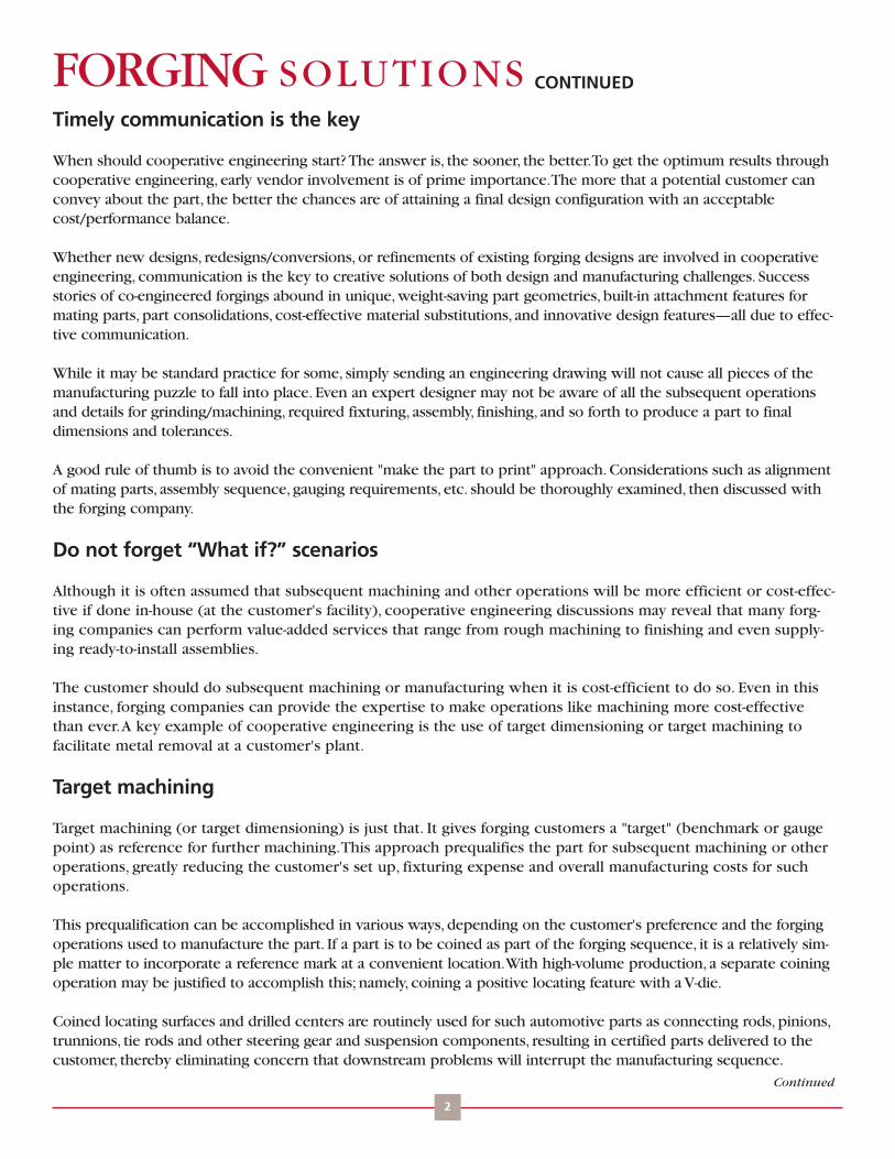
A simple approach to target machining is toutilize punched or drilled holes, which thenestablish the reference or datum plane for allsubsequent gauging and machining. If holes arealready an intrinsic part of a forged design,such as for attachment of mating parts, thegauge point already exists. If not, holes may beadded as long as they do not interfere withpart function. In either case, the forging suppli-er should machine or punch the holes so com-ponents are certified before shipping.Thisremoves the burden and expense of gaugingand inspection, sometimes amounting to a sig-nificant savings for the customer.
'Targets' for large, structuralforgings
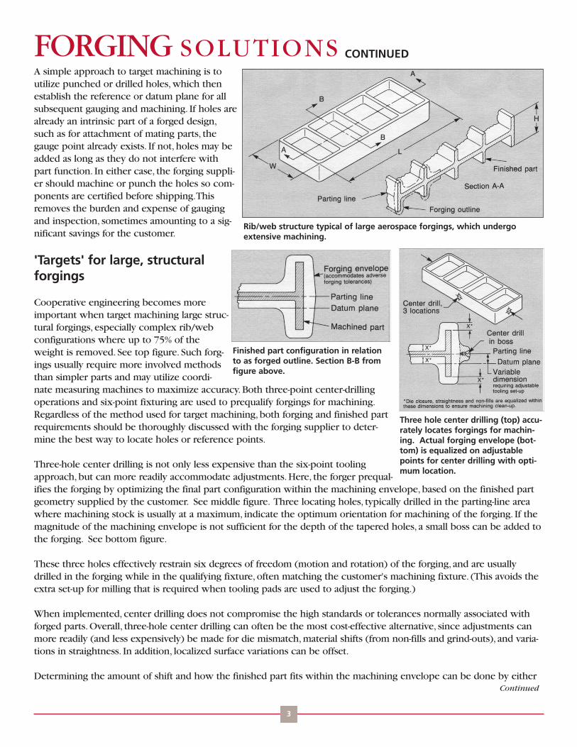
Cooperative engineering becomes moreimportant when target machining large struc-tural forgings, especially complex rib/webconfigurations where up to 75% of theweight is removed. See top figure. Such forg-ings usually require more involved methodsthan simpler parts and may utilize coordi-nate measuring machines to maximize accuracy. Both three-point center-drillingoperations and six-point fixturing are used to prequalify forgings for machining.Regardless of the method used for target machining, both forging and finished partrequirements should be thoroughly discussed with the forging supplier to deter-mine the best way to locate holes or reference points.
Three-hole center drilling is not only less expensive than the six-point toolingapproach, but can more readily accommodate adjustments. Here, the forger prequal-ifies the forging by optimizing the final part configuration within the machining envelope, based on the finished partgeometry supplied by the customer. See middle figure. Three locating holes, typically drilled in the parting-line areawhere machining stock is usually at a maximum, indicate the optimum orientation for machining of the forging. If themagnitude of the machining envelope is not sufficient for the depth of the tapered holes, a small boss can be added tothe forging. See bottom figure.
These three holes effectively restrain six degrees of freedom (motion and rotation) of the forging, and are usuallydrilled in the forging while in the qualifying fixture, often matching the customer's machining fixture. (This avoids theextra set-up for milling that is required when tooling pads are used to adjust the forging.)
When implemented, center drilling does not compromise the high standards or tolerances normally associated withforged parts. Overall, three-hole center drilling can often be the most cost-effective alternative, since adjustments canmore readily (and less expensively) be made for die mismatch, material shifts (from non-fills and grind-outs), and varia-tions in straightness. In addition, localized surface variations can be offset.
Determining the amount of shift and how the finished part fits within the machining envelope can be done by either
Rib/web structure typical of large aerospace forgings, which undergoextensive machining.
Finished part configuration in relationto as forged outline. Section B-B fromfigure above.
Three hole center drilling (top) accu-rately locates forgings for machin-ing. Actual forging envelope (bot-tom) is equalized on adjustablepoints for center drilling with opti-mum location.
Continued

CONTINUEDof two ways, both of which require checking numerous positions along the forg-ing to accurately locate the center-drilled holes. One method involves the use oftemplates (identical to the forging's shape), located at a specified stand off dis-tance (e.g., 0.5 in.) beyond the largest forging and takes into account any shiftingof the forging. See top figure. Here, two "go/no-go" gauge balls are used.
An even more accurate, but slower, method makes use of dial indicators to meas-ure the gap around the forging.This results in better positioning of the forgingwithin the envelope, effectively optimizing center drilling.
The 6-point tooling method makes use of as-forged external features to orient theforging for machining. See bottom figure. However, this method cannot accom-modate shifts of the forging within the machining "envelope" to improve straight-ness, to allow for die closure and mismatch, or to adjust for excess material onone side of the parting line and non-fill on the opposite side. In practice, someadjustment is possible if raised pads (which are milled down to the properheight) are added to the forging, or if movable tooling points (which require addi-tional set-up time by a machinist) are used. Ordinarily, a forger mills the toolingpads and then ships a "qualified" part to the customer. Consequently, machiningoperations at the customer's plant can be accomplished by using the toolingpoints.
Templates and go/no-go clearance bolls—or dial indicators—are used to checkforgings prior to center drilling.
FORGING SOLUTIONS
FORGING INDUSTRY ASSOCIATION25 West Prospect Ave., Suite 300, Cleveland, OH 44115Phone: 216-781-6260 Fax: 216-781-0102 E-mail: [email protected] Website: www.forging.org
© Copyright 2007, Forging Industry Association
Simple six point fixturing for machining of a forging. In practice,the forging is first set on the three "A"points then moved against the two"B" tolling points, and finally againstthe "C" point, restraining the part insix degrees of motion (translation androtation). Clamps hold the forgingagainst the tooling points during thecutting operations.

FORGINGS SUPERIOR TO CASTINGS DUE TOLONG-TERM PERFORMANCEIt is no surprise that forgings routinely outperform castings in ahost of applications. High structural integrity, maximum strength,improved toughness, longer life, and optimum reliability are just afew of the many reasons.
When designers are not sure if a casting will perform, forging isoften designated as the alternate process on engineering drawings.In the past, castings were erroneously selected as a first choice,based on the false assumption that they would cost less.Unfortunately, many castings failed to show repeatable perform-ance in service, making the original "select casting for price"approach a moot point. In fact, the extended service life of forgingsoften makes them less expensive in the long run, even if forgingshave a slightly higher initial cost.
When castings are selected as the result of an uninformed decision,rejects, rework, quality problems, and more can create productiondelays for the OEM customer because metal components cannot bedelivered on time.This was the case when a critical tank compo-nent was first specified as a centrifugal casting, because forgings were considered noncompetitive with castingsfrom a cost standpoint. In the end, forgings not only outperformed castings, but also delivered an improved designat lower cost.
Although it is generally accepted that castings perform reasonably well under compressive stress, they usually can-not compete with forgings in applications where toughness and durability are the main requirements. In the orderof greatest property advantage, forgings routinely outperform castings under impact, shear, and tensile loading.
Castings should not be selected by the designer on the promise of lower initial cost without taking into accountsuch factors as forgings' higher strength-to-weight ratio, which allows reduced section sizes and lighter-weightcomponents.This can be a big contributor to cost effectiveness when implemented in component designs.
Additionally, the initial cost of some forgings can be less than that of cast counterparts when the component is ini-tially and cooperatively designed as a forging. This allows customers and forgers to take full advantage of cost sav-ing design features and manufacturing economics.
Forgings are becoming more cost-competitive with a wider range of cast products as usage of microalloyed steelsgrows. Forged microalloyed steel can replace ductile iron and ADI (austempered ductile iron) in automobile crank-shaft and diesel camshaft applications with cost savings at production volumes. See figure above. Beyond the cost
Design Engineering Information From FIA
FORGINGSOLUTIONS
Addressing these processes:
Impression Die
Open Die
Rolled Ring
Cold
1
Continued
Forged microalloyed steel crankshafts areless expensive than ADI and conventional-ly forged steel versions and become competitive with nodular irons castings athigh production volumes.
160
140
120
100
90
60
40
Co
st, $
/par
t
0 50 100 150 200 250 300Annual Production, thousands
Microalloy Forging
Steel Forging
ADI Casting
Nodular Castings

CONTINUEDFORGING SOLUTIONS
2
issue, the main drivers for the change are consumer demand for higher-performance components and the needto meet more stringent EPA regulations and CAFE (corporate average fueleconomy) standards.
Advantages of forgings versus castingsMany impressive characteristics and superior properties allow forgings tooutperform castings in a wide variety of applications.The main perform-ance advantages of forgings include:
• Structural integrity of forgings, which far surpasses that of castings,makes forgings far less prone to failure. Not infrequently, the inherent dis-continuous structure of castings—notably porosity, large inclusions and seg-regation effects-are commonly the cause for in-service failures. See figure onthe right.
In castings, these discontinuities often become sites for stress concentra-tions, fatigue crack initiation, and finally, catastrophic failure. Examples offorgings replacing casting due to such failures include: a high-temperaturesteel for high-pressure submarine applications; a 5,000 psi hydraulic compo-nent (aluminum die casting leaked); an open-die-forged steel shovel hub formining (casting cracked); and a critical component for truck brakes (low-strength porous casting prompted safety concerns).
In the aerospace sector, forged stainless and nickel alloys for fuel compo-nents of commercial turbines proved that investment castings could notmatch the inherent quality of forging.This application was actually shownto be as cost-effective as a forging in combination with CNC machining.Chemical segregation, also associated with casting, is not a significant factor with forgings, which have a veryhomogeneous microstructure and chemical composition. Because of the amount of reduction performed oningot or bar during forging, centerline porosity is practically nonexistent.
•Grain flow optimization, an intrinsic advantage of forgings, results in orienting the grain structure with a part'sgeometry, permitting strength to be aligned in the direction of the highest stress which a component willencounter in service.The net effect results in enhanced strength, toughness, fatigue properties, and longer life.Unfortunately, the solidification of castings produces a random grain orientation, which cannot be optimized.Examples where controlled grain flow provides dramatically improved performance over castings include: auto-motive and truck crankshafts, wheels for all types of vehicles, a 1-ton connecting rod for coal slurry pumps, anddragline chain links for strip mining.
• Greater strength in forgings is accomplished through hot-forging reduction, an integral part of forging process-es that also helps produce a homogeneous microstructure by eliminating porosity.This allows forging to attainultimate tensile strengths above 240,000 psi with correspondingly high design strengths; higher, for ultra-high-strength steels and precipitation-hardening stainless steels.Tremendous improvements in as-cast properties are achieved by this reduction. For example, true stress at failurefor quenched and tempered 4140 steel increases from 200,000 psi (as-cast) to 243,000 psi after a 4:1 reduction.In parallel, impact toughness increases by 50%. Such properties are responsible for many forging successes,where castings just cannot handle the loads. Such was the case when sand castings were tried as the main struc-tural components for a missile system—insufficient strength resulted in failure. Fortunately, the forging "alternate"performed within design requirements.
Continued
The microstructure of 6061-T6 aluminum forging (top) shows noporosity and has a finer grain sizeas compared to the A206 casting(bottom).
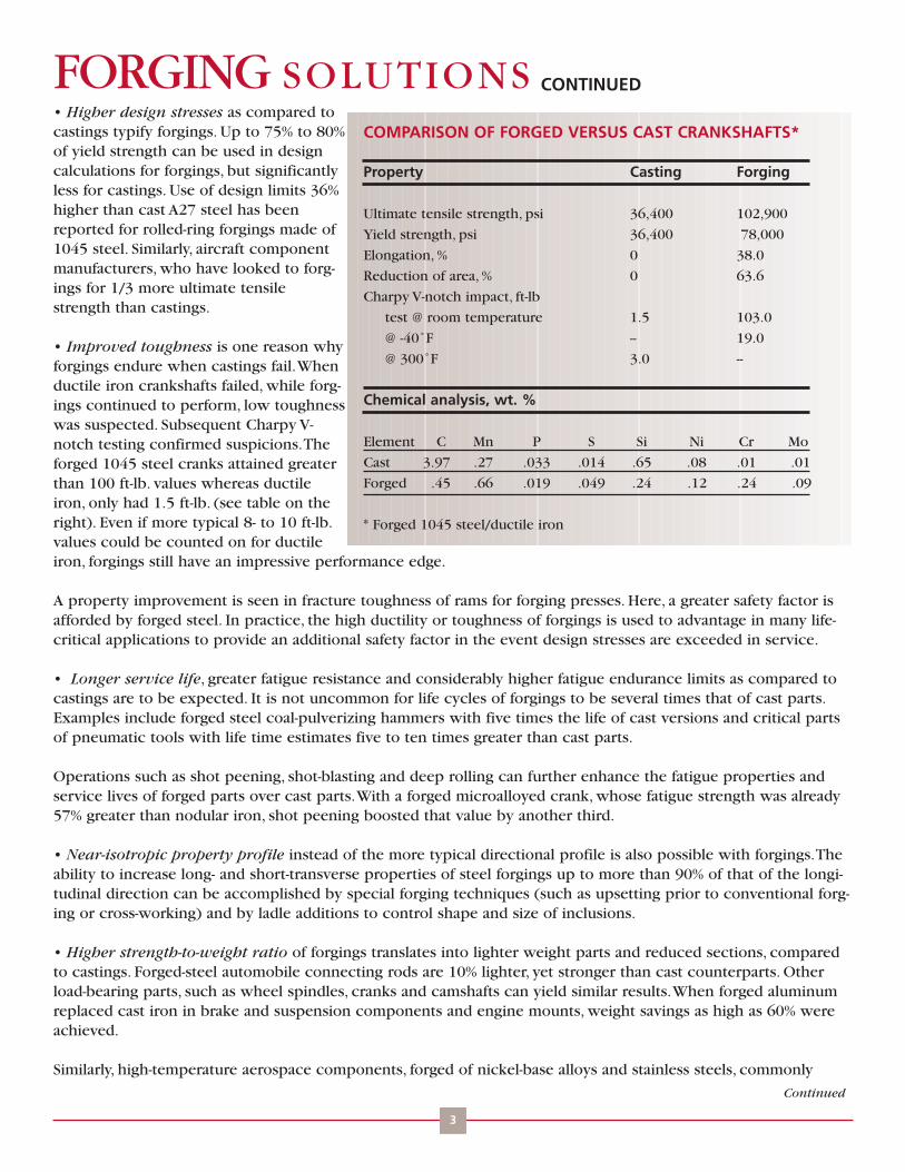
CONTINUEDFORGING SOLUTIONS
3
• Higher design stresses as compared tocastings typify forgings. Up to 75% to 80%of yield strength can be used in designcalculations for forgings, but significantlyless for castings. Use of design limits 36%higher than cast A27 steel has beenreported for rolled-ring forgings made of1045 steel. Similarly, aircraft componentmanufacturers, who have looked to forg-ings for 1/3 more ultimate tensilestrength than castings.
• Improved toughness is one reason whyforgings endure when castings fail.Whenductile iron crankshafts failed, while forg-ings continued to perform, low toughnesswas suspected. Subsequent Charpy V-notch testing confirmed suspicions.Theforged 1045 steel cranks attained greaterthan 100 ft-lb. values whereas ductileiron, only had 1.5 ft-lb. (see table on theright). Even if more typical 8- to 10 ft-lb.values could be counted on for ductileiron, forgings still have an impressive performance edge.
A property improvement is seen in fracture toughness of rams for forging presses. Here, a greater safety factor isafforded by forged steel. In practice, the high ductility or toughness of forgings is used to advantage in many life-critical applications to provide an additional safety factor in the event design stresses are exceeded in service.
• Longer service life, greater fatigue resistance and considerably higher fatigue endurance limits as compared tocastings are to be expected. It is not uncommon for life cycles of forgings to be several times that of cast parts.Examples include forged steel coal-pulverizing hammers with five times the life of cast versions and critical partsof pneumatic tools with life time estimates five to ten times greater than cast parts.
Operations such as shot peening, shot-blasting and deep rolling can further enhance the fatigue properties andservice lives of forged parts over cast parts.With a forged microalloyed crank, whose fatigue strength was already57% greater than nodular iron, shot peening boosted that value by another third.
• Near-isotropic property profile instead of the more typical directional profile is also possible with forgings.Theability to increase long- and short-transverse properties of steel forgings up to more than 90% of that of the longi-tudinal direction can be accomplished by special forging techniques (such as upsetting prior to conventional forg-ing or cross-working) and by ladle additions to control shape and size of inclusions.
• Higher strength-to-weight ratio of forgings translates into lighter weight parts and reduced sections, comparedto castings. Forged-steel automobile connecting rods are 10% lighter, yet stronger than cast counterparts. Otherload-bearing parts, such as wheel spindles, cranks and camshafts can yield similar results.When forged aluminumreplaced cast iron in brake and suspension components and engine mounts, weight savings as high as 60% wereachieved.
Similarly, high-temperature aerospace components, forged of nickel-base alloys and stainless steels, commonly
Continued
COMPARISON OF FORGED VERSUS CAST CRANKSHAFTS*
Property Casting Forging
Ultimate tensile strength, psi 36,400 102,900
Yield strength, psi 36,400 78,000
Elongation, % 0 38.0
Reduction of area, % 0 63.6
Charpy V-notch impact, ft-lb
test @ room temperature 1.5 103.0
@ -40˚F -- 19.0
@ 300˚F 3.0 --
Chemical analysis, wt. %
Element C Mn P S Si Ni Cr Mo
Cast 3.97 .27 .033 .014 .65 .08 .01 .01
Forged .45 .66 .019 .049 .24 .12 .24 .09
* Forged 1045 steel/ductile iron

CONTINUEDweigh 5% to 10% less than castings.Weight savings for preci-sion aluminum forgings are considerably greater.
As-forged surfaces, built-in design features and thin ribs andwebs contribute to such savings, rivaling the near-net-shapecapability of any other process including casting. Features suchas flanges, ribs and webs all have to be thicker in castings toachieve strength levels of forgings.
• Surface quality routinely surpasses that of casting becauseforgings feature 100% density and homogeneous materialthroughout. Repair work via welding, which is often required tobring castings up to par in bearing and structural applications,is not necessary with forgings. Denser surfaces (no voids, inclu-sions, etc.) are a benefit even with non-structural forged parts.For example, forged-brass decorative flagpole tops exhibited avery dense surface - smooth enough to replicate fine detailseven after subsequent chrome plating, if desired. No porosityproblems were found.
• Improved machinability also typifies forgings due to a con-sistent chemical composition and uniform microstructure.Unlike castings, there are no voids, inclusions and segregatedhard spots to interfere with machining operations. Many appli-cations in which forgings have shown improved machiningover castings have been documented, among them: microal-loyed crankshafts, hydraulic components, and rolled-ring forg-ings. In addition, some free-machining steel grades are routinelyforged, thereby improving both the ease and economy ofmachining.
Many other performance advantages of forgings have beendemonstrated time and time again, most of which appear in theaccompanying box (see table on the right).While castings dohave their application niches as far as metal components go,forging companies believe that the overall higher performanceof forged products make them a "must" for critical components.Importantly, even non-critical parts where strength is not theprime issue may become economical as forgings due to extended life cycles.
FORGING SOLUTIONS
FORGING INDUSTRY ASSOCIATION25 West Prospect Ave., Suite 300, Cleveland, OH 44115Phone: 216-781-6260 Fax: 216-781-0102 E-mail: [email protected] Website: www.forging.org
© Copyright 2007, Forging Industry Association
ADVANTAGES OF FORGINGS OVERCASTINGS
Higher strength
Unmatched toughness
Longer service life
Higher structural integrity (absence of
internal defects)
Higher design stresses
Greater transverse properties
Increased safety margin (due to high
ductility)
Greater strength-to-weight ratio (lighter
parts, reduced sections)
100% density (no porosity)
Higher overall quality/reliability
Reduced product liability concerns
Reduced testing requirements
More acceptable parts/fewer rejects
No welding repair required (uniform
consistent material throughout)
More predictable heat-treat response
More uniform properties (lot to lot, and part
to part)
Directional or isotropic property profile
More consistent machining (uniform
microstructure and chemical composition)
Better hardness control for abrasion/wear
resistance
Extended warranties more probable on
critical parts/assemblies
More versatile processing options and
combinations (upsetting, then forging;
forging plus coining, etc.)

FORGED RINGS: THE ULTIMATE IN INTEGRITYAND PROPERTIESForged rings represent the bestoption for any metal component witha ring-like geometry. In practice, theintrinsic advantages of forging arerealized, such as optimum structuralintegrity combined with a maximizedproperty profile. Compared to alterna-tives like castings, weldments, andflame-cut plate, forged rings deliverhigher strength and toughness.Thesetwo superior properties translate intolonger life for forged ring products,like gears and bearings. In criticalapplications like solid-rocket motorcasings, longitudinal welding provedearly on to be of insufficient strength.Only seamless rolled rings can pro-vide the needed properties.
Across the applications board, manu-facturers who require the highest reliability in their critical components select forgings for gears, bearings, andother ring-like products in heavy-duty trucks, off-road equipment, mining machinery, ocean-going vessels, aircraft,and energy-generating equipment. High reliability is especially important in safety-critical applications like con-struction cranes.
Designers have long known that properties of forgings exceed those of other alternatives, and seamless rolledrings are no exception to this rule. For example, large-diameter cast steel gears, which were difficult to machine(wearing out tools at rapid rates), and whose teeth fractured prematurely in service, exhibited strength and tough-ness values significantly lower than those of forged products. Naturally, the designated solution to this problemwas rolled rings. (Property comparisons are shown in table above.)
Producers of forged rings have demonstrated time and again that yield strength is higher and that a more refinedstructure is achieved when compared to their cast counterparts. Microstructurally, the higher properties of forgedrings are the direct result of circumferential grain flow, imparted when a hot metal donut-shaped blank or preformis continually worked into its near finished shape either on a ring-rolling mill or forged over a mandrel. In effect,this orients strength with part geometry so that the forging will perform optimally in service.When contourrolling is utilized to produce an integral flange or more intricate cross-section, the grain flow is then extended intothe flange area. Integral flanges are generally preferred to simply machining a flange out of a rectilinear ring.
Design Engineering Information From FIA
FORGINGSOLUTIONS
Addressing these processes:
Impression Die
Open Die
Rolled Ring
Cold
1
PROPERTIES OF FORGED VERSUS CAST RINGS*
Composition Yield strength Tensile strength Red. of area, %psi psi
A (cast) 74,000 108,300 35.0A (forged 88,750 117,500 54.6B (cast) 85,750 123,700 32.2B (forged) 120,000 141,000 46.2C (cast) 80,700 111,800 42.5C (forged) 99,000 127,500 52.2
Comp., % C Mn Si Cr Ni MoA: .42 .72 .42 .00 .17 .02B: .42 .70 .42 .57 .12 .02C: .43 1.11 .43 .00 .12 .04
*Important note: Forged specimens actually taken from rolled rings by FIA member co. and tested. Cast data is from ideally oriented keel block specimens,so properties from actual cast rings could be significantly less.

CONTINUEDFORGING SOLUTIONS
2
While casting results in randomly oriented grain flow,property values of forgings are generally superior in anyselected direction.With torch-cut plate, the cutting inter-rupts the unidirectional grain flow making the part moresusceptible to fatigue. No matter how it is fabricated, aring which incorporates a longitudinal weld has thepotential problems of inadequate strength, dimensionaldistortion (because of the seam) and HAZ (heat-affectedzone) effects which can produce regions that are toohard, inclusions, porosity and other defects that affectperformance. In practice, a girth weld is preferred over alongitudinal weld, because the stresses in the axial direc-tion are only about half that of the hoop stress to whicha longitudinal weld would be subjected.
Rolled rings also can outperform welded parts, cost-wise.For example, a rolled ring gear-sprocket application replaced a butt-welded product that started with a straight barthat was bent into a circular pattern until the two ends meet, and was then welded.The rolled ring cost significantlyless than the welded version, even when the cost of heat-treating was included in the ring price. Similarly, rolled ringshave replaced gears made from heavy-wall tubing and have also been cost effective. See figure above.
There are two process options for forged rings: seamlessring rolling and forging rings over a mandrel. Both are usu-ally classified as open-die forging processes. However, cer-tain configurations (usually more complex cross-sections)may be made by a combination of ring rolling and closed-die forging. For example, the basic rolled-ring shape maybe put into a die, then hammer or press-forged into a bevelgear or T-section, which is then subsequently machined.
Impressive advantages
The biggest advantage of forged rings is the ability tomake a high-strength, ring-shaped component in one-piece with minimal material loss. Compared to torch-cutplate, up to 50% material savings can be achieved. Not sur-prisingly, the flame-cut customer will be forced to pay for such material waste. Even when theoretically speaking,a tremendous material loss is associated with cutting plate. See bottom figure.
Before it is rolled, the final ring blank typically weighs about 95% of the starting billet.A minimal loss is attributedto the small hole or web punched in the preform for mounting on the machine.This translates into cost savingsover plate due to the material conservation. Contoured rings, whose inner diameters and outer diameters arerolled to shape, also save material by reducing the metal removed by machining. Often, only minimal cleanup orfinish machining is needed.
Other advantages of forged rings include: less distortion in heat treatment; predictable and efficient machinabili-ty; quicker deliveries than fabrication by extrusion, bending, then welding (aluminum); fast set-ups to accommo-date small runs; and close-to-finish cross-sections that can only be achieved by extensive machining.Low tooling costs are also typical with seamless rolled rings, varying slightly with equipment, but especially witha contour on the inner diameter or outer diameter. Generally, inner diameter contouring is readily done, even in
Continued
Rolled steel rings have replaced more costly heavy walltubing, which was cut to shape and contoured into ringgears.
WASTE
Material conservation for a ring forging is typically 95% ascompared to a cutting the ring from a plate.

CONTINUEDFORGING SOLUTIONS
3
short runs. Outer diameter contouring typically must be justified with at least a shift's worth of production,because of the labor cost involved in changing over the main contoured drive roll.With saddle/mandrel set-ups, notooling cost is involved. Standard tooling of varying size is normally in stock.
Like other forged products, forged rings are also the best in terms of structural integrity. Inclusions, macrosegrega-tion and porosity, which typically detract from the service life of castings for bearing and gearing applications, arenot much of a factor with forgings. Similarly, plate may contain laminations and porosity, which also detract fromperformance. Since forgings do not contain these types of defects, fatigue and service lives of forged products aretypically longer.
Large rings, small rings, flat rings, tall ringsFor forged-ring components, size and weight capability is indeed broad. Outer diameters span the gap from a fewinches up to about 30 ft. Inner diameters range from just under 2 in. up to the thinnest wall that can be achievedwith a maximum outer diameter. However, the majority of rolled rings have outer diameters ranging from about 9in. to 4 ft. Face heights (widths) go from fractions of an inch up to almost 10 ft.Weight-wise, forged rings rangefrom less than 1 lb. up to more than 300,000 lbs. Because of equipment limitations, the size range of contouredrolled rings is somewhat less.
Basic shapes go from flat-washer configurations to tall thin-walled cylinders (e.g., for motor casings).Typical thick-ness-to-height ratios range from 16:1 up to 1:16, although special equipment can extend that range.
Typical quantities for seamless rolled rings range from a few pieces up to thousands, depending on their diameterand whether they are contoured or not. In general, saddle/mandrel forging is used to produce rings with heavywall thicknesses or rings with large face heights and small inner diameters, and usually in smaller quantities.
Contouring closer to net shapeWhile a straight rectangular ring is perhaps the simplest shape, contouring of rings makes the number of possiblecross-sections and design options virtually limitless. Usually, contoured rings are shaped by rolls speciallymachined to replicate the inside or outside contours. Savings in materials, machining operations, and secondaryprocessing normally preclude other non-forging process options. Inevitably, many high-reliability, safety-criticalcomponents can only be made this way, because required property profiles can only be achieved by forging.
Applications aboundApplication-wise, there seems to be no limit to the success of forged rings, primarily because of their structuralintegrity, high strength, good toughness, and long life versus competitive components.Very large seamless rolledrings, up to a diameter of 250 in., have routinely replaced both fabrications and castings for riding tires and rollersof rotary kilns and industrial dryers because of their superior performance. Similarly, high-speed gears-made as 120to 150 in. rolled rings, and then machined-yield high performance in marine propulsion systems for ocean-goingvessels, power-generating equipment and rocket-motor casings.
Moderately sized forged rings continue to proliferate in gears and bearings for transmissions, drive trains andwheels for heavy trucks, off-road equipment, locomotives, tractors, and automobiles. Overall, bearing makers findthat the wear factor of shaped, rolled rings is considerably better than bearing races cut from tube or from bar.
Cost/performance benefits of forged rings occur in many applications, spanning virtually every industry. Examplesinclude:• cutter discs, contour ring-rolled with a tapered OD, for boring tunnels through rock, mountains and tunnel work;• rings for pipe connectors in the oil industry;• crusher rings for pulverizing coal (which is fed into power-generating systems); alternately for crushing rock or
for making granules for roofing shingles; and• shaped, stainless steel ring molds for palletizing cattle food.
Continued

CONTINUEDMaterialsMaterials for rings run the gamut from high-strength andtemperature-resistant alloys for aircraft/aerospace applica-tions to carbon and alloy steels for commercial applica-tions. Bearing rings-inners and outers, cups and cones, andspherical bores-are typically made of 52100 alloy.Nonferrous materials include aluminum, copper, titanium,and nickel-based alloys. Among the more exotic materialsthat are ring-rolled are Inconnel 718 and Waspalloy. Inshort, virtually any forgeable engineering alloy can bemanufactured into forged ring shapes.
Use of technologyAutomated manufacturing, statistical problems solving(SPS) and process modeling have been implemented toboost quality, manufacturing efficiency and cost-effective-ness of forged rings.
Automated ring rolling processes have integrated systemsin which bar stock is fed into one end and finished ringsare ejected on the other.All processing, including intermediate steps of blank making, rolling, sizing, and others, isdone automatically. In parallel are forging cells for saddle/mandrel rings where the entire processing sequence,including heat treatment, is controlled from a computer. For both approaches, noteworthy advantages have yieldedmore consistent dimensions from part to part, higher productivity, and more cost-effective forged products.
Statistical process control (SPC) techniques have been implemented to conserve material, improve processing, andmodify equipment for the better, all in the interest of quality improvement and customer savings. Normal-distribu-tion analyses used to reduce stock size of rolled rings are typical of this approach. See figure above.
Process modeling can also be done using finite element analysis to evaluate roll filling and defect formation in pro-filed rings. Such programs can shorten lead and design times, improve quality, and reduce costs of rolled rings.
FORGING SOLUTIONS
FORGING INDUSTRY ASSOCIATION25 West Prospect Ave., Suite 300, Cleveland, OH 44115Phone: 216-781-6260 Fax: 216-781-0102 E-mail: [email protected] Website: www.forging.org
© Copyright 2007, Forging Industry Association
Stock allowances on the inner diameters and outer diame-ters of a 297 lb. seamless rolled ring were reduced by sta-tistical process control methods. After analyzing the"before" data the ring roller was confident enough in theCpk (process capability index) to reduce the weight of the4120 steel rings by more than 9 lbs. The Cpk after thereduction confirmed that the process was still capable.
15.0
10.0
5.0
0.0
Perc
ent
of
Tota
l
“After”Cpk = 1.015
Mean
28.079 28.199 28.318
<LSL = 28.070 Ring OD, in. USL = 28.320>

FORGING FUNDAMENTALS: THE KEY TO OPTIMUM DESIGN PRACTICETo all but the most seasoned designers, the conceptof forging fundamentals may at first appear trivial. Butthat is not the case. In practice, material- and process-related forging basics can be invaluable. For instance,realizing that certain part shapes are more forgeablein some materials and knowing that the equipmentaffects how closely the material can be forged to itsfinal configuration are just two aspects involved increating the optimum design.
For experienced designers, forgings are the optimumchoice for metal components, even before the designis on the drawing board. Forgings bring superior per-formance; they have higher strength, unsurpassedtoughness, greatest structural integrity, longer servicelife, and maximum reliability, as compared to castings,stampings, weldments, and machined parts.
Once the correct metal alloy is selected, based onminimum design requirements for mechanical and/orphysical properties, in-service environmental condi-tions, fatigue life, and more, manufacturabilitybecomes a prime consideration. In practice, creatingthe optimum design for manufacturability takes coop-erative effort among the product designer, the forger,and metallurgical personnel.
The manufacturability of a forging design dependsprimarily on the material being forged, which influences not only the internal soundness of the forging, but alsodetermines important design characteristics and features.These include:• the amount of finish required;• the minimum section thicknesses that can be achieved;• the degree of shape refinement or part complexity;• the magnitude of tolerances that can be held; and• size limitations (plan-view area [PVA], length, or width).
Examining forgeability (how easy it is to forge a material without rupture) is a good first step toward evalu-ating manufacturability.This property varies greatly depending on the type of alloy. See figure above.The ability to
Design Engineering Information From FIA
FORGINGSOLUTIONS
Addressing these processes:
Impression Die
Open Die
Rolled Ring
Cold
1
Continued
Materials in the upper left are more easily forged into thewidest variety of intricate part shapes using conventional forging equipment. In the lower right are the least forgeablematerials, which typically require special processing techniquessuch as hot die forging or isothermal forging. Materials in theother boxes fall in between the two extremes. The arrow indicates increasing ease of die filling.
INCREASING FLOW STRENGTH OR FORGING PRESSURE
DEC
REA
SIN
G F
OR
GEA
BIL
ITY
Low Moderate High
Fair
Mod
erat
eG
ood
1030 (carbon steel)
4340 (alloy steel)
H-11 (tool steel)
2014 (aluminum)
AZ80 (magnesium alloy)
7075 (aluminum alloy)
1130 (alloy steel)
Resulphurized steels
Type 304 (stainless)
Ti-6AI-4V (titanium)
A-286 (stainless)
Inco 901(nickel alloy)
17-7PH (stainless)
Ti-5AI-2.5 Sn(titanium)
Type 321(stainless)
15-7Mo(stainless)
Molybdenum
16-25-6 (stainless)
Waspalloy(nickel alloy)
Ti-13V-11Cr-3AI
Inco 718(nickel alloy)
In 100(nickel alloy)
René 95(nickel alloy)
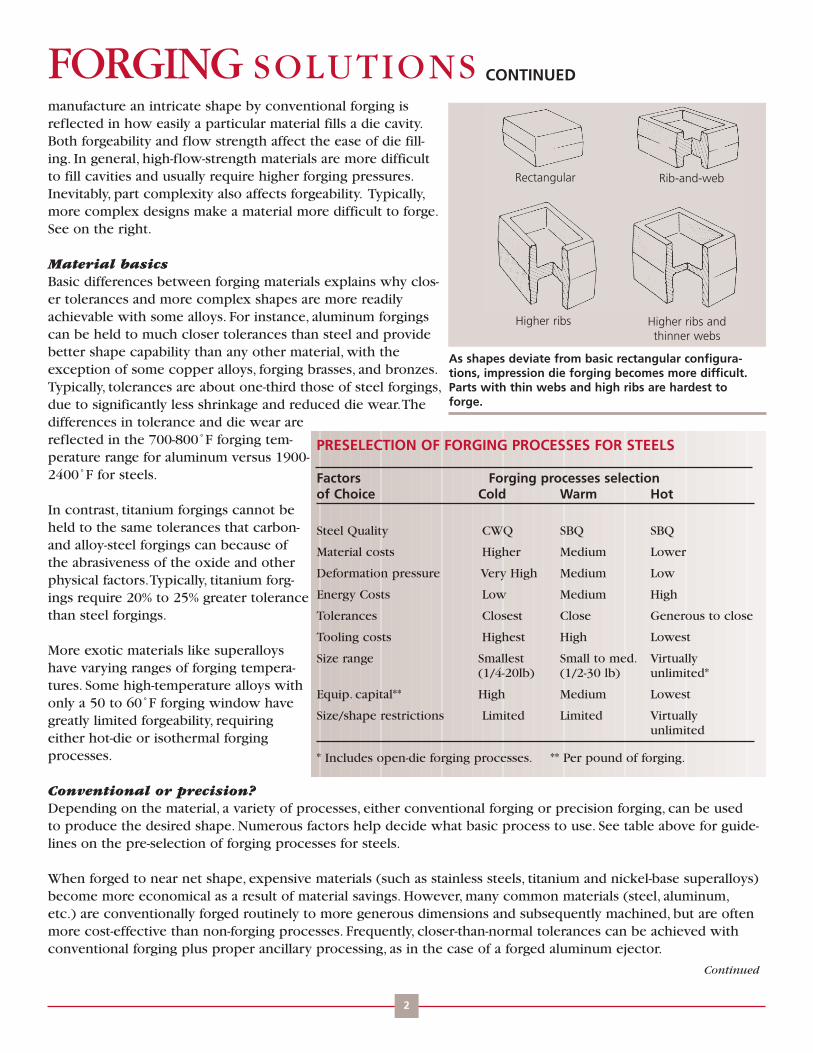
CONTINUEDFORGING SOLUTIONS
2
manufacture an intricate shape by conventional forging isreflected in how easily a particular material fills a die cavity.Both forgeability and flow strength affect the ease of die fill-ing. In general, high-flow-strength materials are more difficultto fill cavities and usually require higher forging pressures.Inevitably, part complexity also affects forgeability. Typically,more complex designs make a material more difficult to forge.See on the right.
Material basicsBasic differences between forging materials explains why clos-er tolerances and more complex shapes are more readilyachievable with some alloys. For instance, aluminum forgingscan be held to much closer tolerances than steel and providebetter shape capability than any other material, with theexception of some copper alloys, forging brasses, and bronzes.Typically, tolerances are about one-third those of steel forgings,due to significantly less shrinkage and reduced die wear.Thedifferences in tolerance and die wear arereflected in the 700-800˚F forging tem-perature range for aluminum versus 1900-2400˚F for steels.
In contrast, titanium forgings cannot beheld to the same tolerances that carbon-and alloy-steel forgings can because ofthe abrasiveness of the oxide and otherphysical factors.Typically, titanium forg-ings require 20% to 25% greater tolerancethan steel forgings.
More exotic materials like superalloyshave varying ranges of forging tempera-tures. Some high-temperature alloys withonly a 50 to 60˚F forging window havegreatly limited forgeability, requiringeither hot-die or isothermal forgingprocesses.
Conventional or precision?Depending on the material, a variety of processes, either conventional forging or precision forging, can be usedto produce the desired shape. Numerous factors help decide what basic process to use. See table above for guide-lines on the pre-selection of forging processes for steels.
When forged to near net shape, expensive materials (such as stainless steels, titanium and nickel-base superalloys)become more economical as a result of material savings. However, many common materials (steel, aluminum,etc.) are conventionally forged routinely to more generous dimensions and subsequently machined, but are oftenmore cost-effective than non-forging processes. Frequently, closer-than-normal tolerances can be achieved withconventional forging plus proper ancillary processing, as in the case of a forged aluminum ejector.
Continued
As shapes deviate from basic rectangular configura-tions, impression die forging becomes more difficult.Parts with thin webs and high ribs are hardest toforge.
Rectangular Rib-and-web
Higher ribs Higher ribs and thinner webs
PRESELECTION OF FORGING PROCESSES FOR STEELS
Factors Forging processes selectionof Choice Cold Warm Hot
Steel Quality CWQ SBQ SBQ
Material costs Higher Medium Lower
Deformation pressure Very High Medium Low
Energy Costs Low Medium High
Tolerances Closest Close Generous to close
Tooling costs Highest High Lowest
Size range Smallest Small to med. Virtually(1/4-20lb) (1/2-30 lb) unlimited*
Equip. capital** High Medium Lowest
Size/shape restrictions Limited Limited Virtuallyunlimited
* Includes open-die forging processes. ** Per pound of forging.

Generally, the process selected (and related forging equipment) affects how closely a material can be forged tofinal dimensions. For example, precision forging of aluminum can yield parts with net-shape surfaces and close tol-erances, while conventional forging may require machining all around the part periphery. For higher alloys likesuperalloys, shape and size limitations become highly equipment-dependent, because of smaller processing win-dows and the need for precise control of metallurgical factors.As a result, these materials generally require muchhigher forging pressures than steel, resulting in parts with smaller plan-view areas and other dimensional con-straints. In contrast, larger steel forgings can often be produced by utilizing higher capacity (tonnage) equipment.The same holds true for many aluminum alloys.
Near or net shapeEmphasis is often on forging closer to net shape or as close as possible to finished contours and dimensions.A fun-damental knowledge of the following options, which collectively apply to most forgeable materials, helps identifythe appropriate process for a given material.
• Hot forging in presses to near-net shapes is possible for most carbon, alloy, and stainless steels, titaniumalloys, heat-resistant alloys, and nonferrous materials.While crank-type drives are more readily automated, screwpresses are ideal for thin parts like turbine blades and provide greater thickness accuracy. Both symmetrical andaxisymmetrical components can be produced. High production quantities are recommended to offset tool designand development costs. Part weights can approach 200 lbs.
• Hot forging in controlled impact hammers to near-net shapes applies to most alloys, except for magne-sium and higher aluminum alloys, such as 7075, 7079, and 7050. Parts with thin sections and close thickness toler-ances are readily manufactured.While lower production quantities are more economical than with presses, shapeversatility is not as great since tooling restrictions (lack of kick-outs) requires draft on part designs. Forgings up toabout 35 lb. can be produced to near-net configurations (even larger if cold coining is used).
• Warm forging in mechanical presses to close tolerances is appropriate for steels and some aluminumalloys. Usually requiring progressive forming steps, this process may use automated induction heating to form pre-conditioned steel slugs. For higher productivity, walking-beam transfers are integral with some machines. Suitablefor forging gears with integral teeth, warm forging often requires some type of cutting operation to hold concen-tricity tolerances on shafts.Typically, tooling costs are moderate to high, and sufficient production quantities areneeded to justify this process. Maximum part weight is about 30 lbs.
• Hot forging in high-speed part formers to close finish usually applies to carbon and low-alloy steels,which are typically made into axisymmetrical parts with low profiles. Parts generally feature no draft and very lit-tle finish allowance.Although production rates can exceed 100 parts per minute, costly machinery and produc-tion-line support equipment requires very large quantities (e.g. automotive) to justify use. Generally, parts weighup to 15 lbs.
• Cold forging processes make use of bending, extrusion, coining, etc. to manufacture parts to close tolerancesor near-net shapes.All are basically chipless. In practice, ferrous materials are restricted to lower alloy and carbonsteels with carbon levels of 0.45% or less; impact extrusions, 0.25% C or less.Although less common, stainlesssteels and aluminum alloys and bronzes can also be cold forged.Typical shapes include cup- and shift-like parts,struts, and headed components and range from 1/4 to 20 lbs. To justify selection, a minimum of 10,000 lbs. ofparts/month is recommended, although there are occasional exceptions to this rough guideline.
• Hot-die forging in conventional presses requires specialized tooling heated to near-forging temperatures inair. Suitable for titanium alloys and nickel-based superalloys, this process is not recommended for stainless or alloysteels. Most parts are modified disk shapes 6 to 36 in. in diameter and weighing from about 70 to 1000 lbs. Forgingof aluminum alloys in heated tools also falls in this category.
CONTINUEDFORGING SOLUTIONS
3
Continued

CONTINUED• Isothermal forging usually applies to nickel-based superalloys prepared initially by powder-metal com-paction.The process is not recommended for steels or stainless steels. Expensive refractory-metal tooling and con-trolled-atmosphere chambers to protect tools and parts from oxidation are standard. Production rates of a fewparts per hour make this process cost-effective for only the highest performance parts. Shapes and sizes are similarto hot-die forging, but with closer tolerances on thickness and somewhat thinner sections.
Size/Shape LimitationsShape/size limitations on forging designs are often limited by the equipment used. For instance, aluminum and tita-nium airframe-type structural components exceeding about 5.5 ft. cannot be forged on many large drop hammersand mechanical presses because the press bed is just not large enough to hold the required tools. Fortunately, largecounterblow hammers can handle parts up to 7 ft. long. Beyond that, large hydraulic presses with 50,000 toncapacities can produce components up to 12 ft. long.
However, the total projected area must still be matched to the press capacity.This tends to restrict longer parts tonarrower widths (within PVA limitations).
Similarly, disk shapes can be forged of steel on large presses of counterblow hammers up to a maximum 65 in.diameter, but are limited to about 38 in. diameters when forged of nickel-base superalloys, except for simple con-figurations and fairly thick shapes.The much higher pressures required demonstrate the tie to forgeability (i.e.harder to forge materials restrict plan-view area and overall size, and may also require higher-capacity machines).The number of companies with the largest forging machines is limited.
The features of different forging machines also affect other important design parameters. For example, parts forgedin hammers must have draft angles for easy removal from impression dies.The lack of built-in ejection systemsmakes "no draft" parts impractical. Similarly, multi-section or segmented dies and inserts, which permit such designfeatures as undercuts, lateral protrusions and back draft in aluminum precision forgings, are feasible primarily forhydraulic presses. In practice, such dies cannot be used in hammers or most mechanical presses.
FORGING SOLUTIONS
FORGING INDUSTRY ASSOCIATION25 West Prospect Ave., Suite 300, Cleveland, OH 44115Phone: 216-781-6260 Fax: 216-781-0102 E-mail: [email protected] Website: www.forging.org
© Copyright 2007, Forging Industry Association
DESIGN FOR FORGINGS-SPECIFICATIONS HELPThinking of specifying a forging? It is probably easier than you think.As is often the case, the reasons why steel cast-ings, flame-cut plate, weldments, machined bar, and others were specified years ago are not necessarily valid or obvi-ous. Informed designers switch to forgings in order to upgrade performance.
There is no need for apprehension if you are only familiar with specifications for casting, structural steel, hot-rolled baror other non-forged product, because cross-references to existing forgings specifications can often be made. Evenwhen they cannot, forging companies can propose alternatives of an equivalent material, but with typically superiorperformance.
Some knowledge of pertinent specifications will definitely help those who are not familiar with forgings.This article isintended to present designers and potential customers with preliminary knowledge of forging specifications to expe-dite the process of upgrading to forgings.
Why specify forgings?The answer is simple: Forgings give higher performance compared to castings, machined parts, weldments, and othermetal components.This includes high mechanical properties, unsurpassed impact toughness, longer service life, greaterstructural integrity, a more homogeneous microstructure (freedom from porosity, gross inclusions, etc.), optimum grainflow orientation, and customized property profiles, among others.
Performance is not the only reason.When upgrading from non-forged parts, some forging customers have been pleas-antly surprised by an initial lower cost for forgings.While the latter scenario is not always the case, most forgings areactually less expensive when compared to other metal components on a life cycle cost basis.The longer life of high-performance forged components makes it so.A switch to forgings can streamline the manufacturing process. Resultingcost savings can be even more significant. Such was the case when a forging replaced a casting in a friction-weldedassembly.
Open die forgings versus non-forged partsBecause of their higher performance, steel forgings routinely continue to replace steel castings. Knowing what specifi-cation to use a particular application to an open die forging is definitely helpful.Although not always simple, cross-ref-erencing commonly used specifications allow designers to more accurately evaluate forging options and actually facili-tate the upgrade process.The comparisons of forging specifications to casting specifications appearing in the table onthe following page cover carbon and alloy steels for various applications and environmental conditions. This is meantto serve as a guideline only, and is not intended as a final recommendation for any particular application.
One of the most-used open die forging specs available, ASTM A668 is a broad-based starting point for anyone wishingto specify open die forgings (see on the next page for more details). It covers carbon through alloy steels and speci-fies a definitive Brinell hardness range, among other requirements. It is useful not only for specifying upgrades to forg-ing from casting, but also for other non-forging alternatives. For example, structural steel shapes, plate, and bar previ-ously purchased under ASTM A36 (Standard Specification for Structural Steel) may be cross-referenced to ASTM A668
Design Engineering Information From FIA
FORGINGSOLUTIONS
Addressing these processes:
Impression Die
Open Die
Rolled Ring
Cold
1
Continued
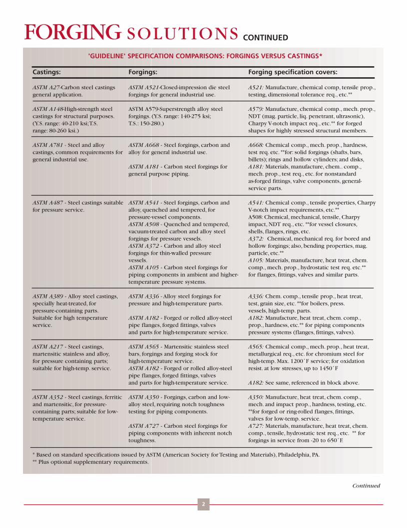
CONTINUEDFORGING SOLUTIONS
2
Continued
'GUIDELINE' SPECIFICATION COMPARISONS: FORGINGS VERSUS CASTINGS*
Castings: Forgings: Forging specification covers:
ASTM A27-Carbon steel castings ASTM A521-Closed-impression die steel A521: Manufacture, chemical comp, tensile prop.,general application. forgings for general industrial use. testing, dimensional tolerance req., etc.**
ASTM A148-High-strength steel ASTM A579-Superstrength alloy steel A579: Manufacture, chemical comp., mech. prop.,castings for structural purposes. forgings. (Y.S. range: 140-275 ksi; NDT (mag. particle, liq. penetrant, ultrasonic),(Y.S. range: 40-210 ksi;T.S. T.S.: 150-280.) Charpy V-notch impact req., etc.** for forgedrange: 80-260 ksi.) shapes for highly stressed structural members.
ASTM A781 - Steel and alloy ASTM A668 - Steel forgings, carbon and A668: Chemical comp., mech. prop., hardness,castings, common requirements for alloy for general industrial use. test req. etc. **for: solid forgings (shafts, bars,general industrial use. billets); rings and hollow cylinders; and disks,
ASTM A181 - Carbon steel forgings for A181: Materials, manufacture, chem.. comp.,general purpose piping. mech. prop., test req., etc. for nonstandard
as-forged fittings, valve components, general-service parts.
ASTM A487 - Steel castings suitable ASTM A541 - Steel forgings, carbon and A541: Chemical comp., tensile properties, Charpyfor pressure service. alloy, quenched and tempered, for V-notch impact requirements, etc.**
pressure-vessel components. A508: Chemical, mechanical, tensile, CharpyASTM A508 - Quenched and tempered, impact, NDT req., etc. **for vessel closures,vacuum-treated carbon and alloy steel shells, flanges, rings, etc.forgings for pressure vessels. A372: Chemical, mechanical req. for bored andASTM A372 - Carbon and alloy steel hollow forgings; also, bending properties, mag.forgings for thin-walled pressure particle, etc.**vessels. A105: Materials, manufacture, heat treat, chem.ASTM A105 - Carbon steel forgings for comp., mech. prop., hydrostatic test req. etc.**piping components in ambient and higher- for flanges, fittings, valves and similar parts.temperature pressure systems.
ASTM A389 - Alloy steel castings, ASTM A336 - Alloy steel forgings for A336: Chem. comp., tensile prop., heat treat,specially heat-treated, for pressure and high-temperature parts. test, grain size, etc. **for boilers, press.pressure-containing parts. vessels, high-temp. parts.Suitable for high temperature ASTM A182 - Forged or rolled alloy-steel A182: Manufacture, heat treat, chem. comp.,service. pipe flanges, forged fittings, valves prop., hardness, etc.** for piping components
and parts for high-temperature service. pressure systems (flanges, fittings, valves).
ASTM A217 - Steel castings, ASTM A565 - Martensitic stainless steel A565: Chemical comp., mech. prop., heat treat,martensitic stainless and alloy, bars, forgings and forging stock for metallurgical req., etc. for chromium steel forfor pressure containing parts; high-temperature service. high-temp. Max. 1200˚F service; for oxidationsuitable for high-temp. service. ASTM A182 - Forged or rolled alloy-steel resist. at low stresses, up to 1450˚F
pipe flanges, forged fittings, valvesand parts for high-temperature service. A182: See same, referenced in block above.
ASTM A352 - Steel castings, ferritic ASTM A350 - Forgings, carbon and low- A350: Manufacture, heat treat, chem. comp.,and martensitic, for pressure- alloy steel, requiring notch toughness mech. and impact prop., hardness, testing, etc.containing parts; suitable for low- testing for piping components. **for forged or ring-rolled flanges, fittings,temperature service. valves for low-temp. service.
ASTM A727 - Carbon steel forgings for A727: Materials, manufacture, heat treat, chem.piping components with inherent notch comp., tensile, hydrostatic test req., etc. ** fortoughness. forgings in service from -20 to 650˚F.
* Based on standard specifications issued by ASTM (American Society for Testing and Materials), Philadelphia, PA.** Plus optional supplementary requirements.

Class D, which calls out tensile requirements as a function of size.
In addition to upgrading for performance reasons, such components as thick-walled tubing, flat bar, plate, hollows, etc.often become forgings because the desired stock sizes of non-forged products are not available.Typically, dimensionssuch as length, outside diameter, wall thickness, etc. are not as limited in forged products, thereby increasing designflexibility.
Similarly, seamless tubing purchased under ASTM A106-91 (Seamless Carbon Steel Pipe for High-Temperature Service)may be specified as a forging under A105 (Standard Specification for Forgings, Carbon Steel, for Piping Components).This option is sometimes preferred for short runs of hollow seamless rounds in short lengths, namely forged or rolledrings.
Impression die forgingsAs with open die counterparts, existing specifications for impression die forgings provide a relatively easy way to initi-ate an upgrade.Targeted at impression die forgings in general,ASTM A521 covers untreated carbon steel forgings upthrough normalized and quenched-and-tempered alloy steel forgings, detailing most of the design parameters that helpmake forgings the metal component leader.A good starting point for those not as familiar with forgings, this compre-hensive specification includes key requirements for chemical composition, mechanical properties, testing, and dimen-sional tolerances—length/width, die wear, die closure, die match, flash extension, straightness, surface, draft angle, andfinish allowance.When applications so demand, supplementary requirements—magnetic particle, grain flow, impact,microstructural, ultrasonic, radiographic, andBrinell hardness—can be specified.Thespecification also separately addresses forg-ings made on hammers/presses or on forg-ing machines (upsetters).This general speci-fication also appears in the previous table.
Greater ductility, reflected in significanttoughness improvements, is definitely animportant factor in the resulting superiorperformance of forgings.As is almost alwaysthe case, this improvement is indicated byhigher percent-elongation and reduction-of-area values for forged versus non-forgedproducts.The table on the right comparesminimum specification values for impres-sion die forging versus casting.The clearadvantage that forgings typically possess isreadily seen in the calculated percentagegains.
It is estimated that there are hundreds offorging-related ASTM specifications, any ofwhich may be useful for a particular appli-cation. Beyond "general" specifications,others cover various applications by enduse category (rail, air, automotive); by envi-ronmental conditions (high temperature,pressure, low temperature); and even by
CONTINUEDFORGING SOLUTIONS
3
MIN. ELONGATION, RED, OF AREA FOR IMPRESSION DIE FORGINGS VERSUSCASTINGS*
ASTM spec Grade or Elong. Gain Red. of Gain, Ten./Yield Thick,Class % % elong. area, % R of A str., ksi in.**
A148a Casting 115-95 14 --- 30 --- 115/95 ---A521b Impression AFc 16 14% 50 67% 125/105 <4die forging 16 14% 45 50% 115/96 4-7
A148a Casting 90-60 20 --- 40 --- 90/60 ---A521b Impression ACd 22 10% 44 10% 90/60 <7die forging
A148a Casting 80-40 18 --- 30 --- 80/40 ---A521b Impression CFe 22 22% 36 20% 80/40 <8die forging
A27f Casting 70-36g 22 --- 30 --- 70/36 --70-40h 22 --- 30 --- 70/40 ---
A521b Impression CEj 24 9% 40 33% 75/37 <8die forging
*Selected values for cited specs. Issued by American Society for Testing andMaterials, Philadelphia, PA. Based on equivalent tensile and yield strengths.**Or solid diameter.aStandard specification for high strength steel castings for structural purposes.bStandard specification for closed-impression die steel forgings for general industrial use.cAlloy steel, normalized, quenched and tempereddAlloy steel, normalized and tempered.eCarbon steel, normalized and tempered.fStandard specification for carbon steel castings for gen. application.g0.35% C max., 0.7% Mn max.h0.25% C, 1.20% Mn maxjCarbon steel: annealed, normalized or normalized and tempered.
Continued
CONTINUEDFORGING SOLUTIONSthe exact component type (steel rolls for paper machinery, nonmagnetic retaining rings for generators, rings forreduction gears).
In addition, depending on the end use, a variety of standard specifications, for example:ASTM, MIL, QQ(Federal),SAE,ANSI,AMS, ISO, DIN, JIS, etc., may apply to a particular application. Some overlap; some do not.While thismay seem to complicate the upgrade process, a knowledgeable forging company can usually answer specifica-tions questions.
No single specification covers all situations.That is why specifications from ASTM and other standards organiza-tions often include supplemental requirements. Such requirements are negotiable between forger and customer,and can be tailored to fulfill specialized needs and unusual performance requirements.
Practice versus theoryIn reality, a one-to-one cross-reference of a forging specification to a non-forging specification is not always possi-ble. Sometimes, it seems like comparing apples to oranges. But, there is no need to despair. If a part has previous-ly been specified as a casting, machined round bar or other non-forged product, forging companies can offer aviable and economical forging option: namely, a forging that corresponds both compositionally and property-wise to the non-forged product in question. If a casting was previously made to a certain class or grade of materi-al in a cited specification-for example, a 70 ksi tensile strength and 30 ksi yield-these properties can be readilyaccommodated in an equivalent forging material.As a matter of course, improved properties, greater structuralintegrity, and longer service life routinely accompany the choice of a forged alternative.
If you know what design criteria (mechanical properties, impact toughness, fatigue life, endurance limit, environ-mental conditions, etc.) are needed for your application, so much the better. If not, then discuss forging alterna-tives with FIA members who are more than happy to assist in evaluating your application and present you withoptions, which may be just what you are looking for, both economically and performance-wise.
When upgrading, keep in mind that some "caveats" may apply.
1) Forgings should not be produced to casting, structural steel, or other metal-component specifications, becauseeach non-forged alternative has its own special inherent requirements that do not usually apply to forgings.While forging companies can provide forgings to meet or surpass chemical compositions and mechanical prop-erties of non-forging specifications, it definitely makes sense to optimize your particular application.
2) Do not inadvertently switch from a casting or other non-forging spec without thorough review of what therequirements entail. Special requirements like ultrasonic testing, which may not be necessary for a particularapplication, can be automatically invoked by citing a particular specification.When not needed, this just drivesup product cost.
3) Do not try to modify existing non-forging specifications. It is usually not feasible and could be counter-produc-tive. Forging companies suggest that you spend this time contacting them with the details on your potential forg-ing application.They can then suggest a forging alternative to your current non-forged product.
FORGING INDUSTRY ASSOCIATION25 West Prospect Ave., Suite 300, Cleveland, OH 44115Phone: 216-781-6260 Fax: 216-781-0102 E-mail: [email protected] Website: www.forging.org
© Copyright 2007, Forging Industry Association
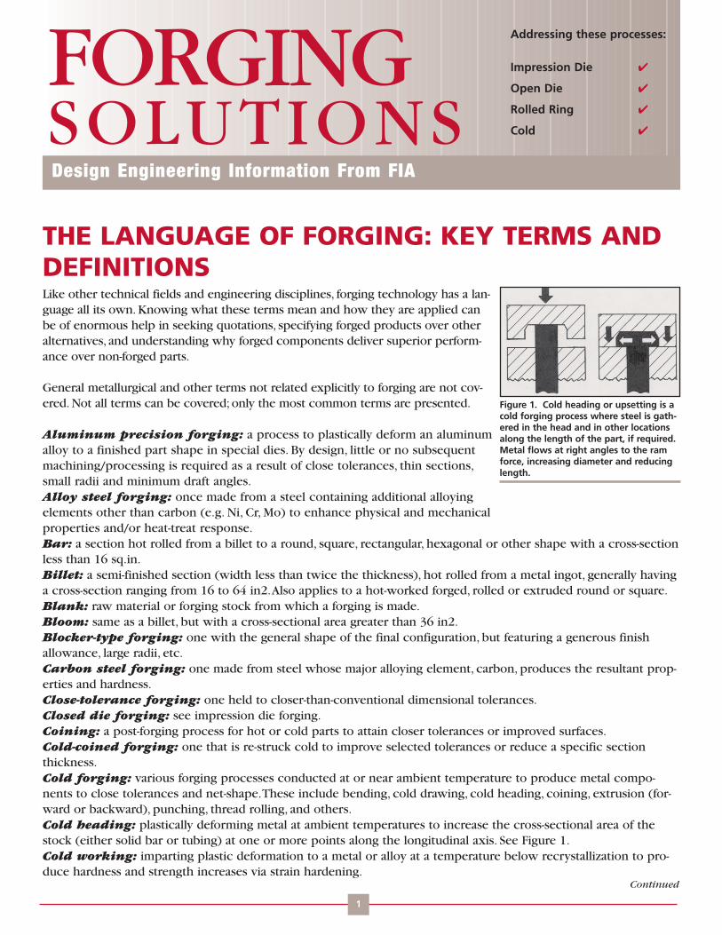
THE LANGUAGE OF FORGING: KEY TERMS ANDDEFINITIONSLike other technical fields and engineering disciplines, forging technology has a lan-guage all its own. Knowing what these terms mean and how they are applied canbe of enormous help in seeking quotations, specifying forged products over otheralternatives, and understanding why forged components deliver superior perform-ance over non-forged parts.
General metallurgical and other terms not related explicitly to forging are not cov-ered. Not all terms can be covered; only the most common terms are presented.
Aluminum precision forging: a process to plastically deform an aluminumalloy to a finished part shape in special dies. By design, little or no subsequentmachining/processing is required as a result of close tolerances, thin sections,small radii and minimum draft angles.Alloy steel forging: once made from a steel containing additional alloyingelements other than carbon (e.g. Ni, Cr, Mo) to enhance physical and mechanicalproperties and/or heat-treat response.Bar: a section hot rolled from a billet to a round, square, rectangular, hexagonal or other shape with a cross-sectionless than 16 sq.in.Billet: a semi-finished section (width less than twice the thickness), hot rolled from a metal ingot, generally havinga cross-section ranging from 16 to 64 in2.Also applies to a hot-worked forged, rolled or extruded round or square.Blank: raw material or forging stock from which a forging is made.Bloom: same as a billet, but with a cross-sectional area greater than 36 in2.Blocker-type forging: one with the general shape of the final configuration, but featuring a generous finishallowance, large radii, etc.Carbon steel forging: one made from steel whose major alloying element, carbon, produces the resultant prop-erties and hardness.Close-tolerance forging: one held to closer-than-conventional dimensional tolerances.Closed die forging: see impression die forging.Coining: a post-forging process for hot or cold parts to attain closer tolerances or improved surfaces.Cold-coined forging: one that is re-struck cold to improve selected tolerances or reduce a specific section thickness.Cold forging: various forging processes conducted at or near ambient temperature to produce metal compo-nents to close tolerances and net-shape.These include bending, cold drawing, cold heading, coining, extrusion (for-ward or backward), punching, thread rolling, and others.Cold heading: plastically deforming metal at ambient temperatures to increase the cross-sectional area of thestock (either solid bar or tubing) at one or more points along the longitudinal axis. See Figure 1.Cold working: imparting plastic deformation to a metal or alloy at a temperature below recrystallization to pro-duce hardness and strength increases via strain hardening.
Design Engineering Information From FIA
FORGINGSOLUTIONS
Addressing these processes:
Impression Die
Open Die
Rolled Ring
Cold
1
Continued
Figure 1. Cold heading or upsetting is acold forging process where steel is gath-ered in the head and in other locationsalong the length of the part, if required.Metal flows at right angles to the ramforce, increasing diameter and reducinglength.

CONTINUEDFORGING SOLUTIONS
2
Controlled cooling: process used to attain required properties and/or correspondingmicrostructural phase changes; applies to heat-treatable steels (e.g. quenching) and tomicroalloyed steels, which require no heat treatment, but only controlled cooling toattain final properties.Conventional forging: one that, by design, requires a specified amount of finish (ormachining) to reach the final dimensional requirements.Counterblow forging: one made by equipment incorporating two opposed rams,which simultaneously strike repeated blows on the work piece.Cross forging: the practice of working stock in one or more directions to make result-ant properties more isotropic (equal in three directions), for example, by upsetting andredrawing the material.Directional properties: refers to the inherent directionality within a forging suchthat properties are optimally oriented to do the most good under in-service conditions.Typically, maximum strength is oriented along the axis that will experience the highest loads.Disk: a "pancake" shaped forging (flat with a round cross-section), such as a blank for gears, rings, and flanged hubs.Draft: the necessary taper on the side of a forging to allow removal from the dies; also applies to the die impression.Commonly expressed in degrees as the draft angle.Draftless forging: a forging with zero draft on vertical walls.Drawing: 1) reducing the cross-section of forging stock while simultaneously increasing the length; 2) in heat treating,the same as tempering.Drop forging: one produced by hammering metal in a drop hammer between impression dies.Extrusion: forcing metal through a die orifice in the same direction as the applied force (forward extrusion) or in theopposite direction (backward extrusion). See Figure 2.Finish: 1) the material remaining after forging that is machined away to produce the final part; 2) the surface conditionof a forging after machining.Finish all over (F.A.O.): designates that forgings be made sufficiently larger than dimensions shown to permitmachining on all surfaces to given sizes.Finish allowance: amount of stock left on the surface of a forging to be removed by subsequent machining.Flash: excess metal that extends out from the body of the forging to ensure complete filling of the finishing impres-sions.Flashless forging: "true" closed die forging in which metal deformed in a die cavity permits virtually no excess metalto escape.Flow lines: patterns that reveal how the grain structure follows the direction of working in a forging.Forgeability: relative ability of a material to deform without failure or fracture.Forging reduction: ratio of the cross sectional area before and after forging; sometimes refers to percentage reduc-tion in thickness.Forging stock: wrought rod, bar, or piece used as the raw material or stock in forging.Free machining steel forgings: those made from steels with special alloying-element additions to facilitatemachining.Grain flow: fiber-like lines that show (via macroscopic etching) the orientation of the microstructural grain pat-tern of forgings achieved by working during forging processes. Optimizing grain flow orientation maximizesmechanical properties.Hammer forging: one produced on a forging hammer, usually between impression dies but sometimes flat dies; theprocess of forging in a drop hammer (see drop forging).Hand forging: one made by manually controlled manipulation in a press without impression dies, usually betweenflat dies with progressive forging of the work piece; also referred to as flat die forging.Heat treatment: heating or cooling operations, sometimes isothermal, to produce desired properties in forgings.High energy rate forging (HERF): forgings made on equipment that utilizes very high ram velocities.Hogout: product machined from bar, plate, slab, or other material.Hollow forging: a cylindrical open die forging; namely, thick-walled tubes or rings. See Figure 3 on the next page.
Continued
Figure 2. Forward extrusion, abasic cold forging process, reducesslug diameter while increasinglength. Stepped shafts and cylin-ders are typical examples of thisprocess.

Hot die forging: a process in which dies are heated closeto the forging temperature of the alloy being forged; used fordifficult-to-forge alloys.Hot forging: same as hot working-plastically deforming analloy at a temperature above its recrystallization point, i.e.high enough to avoid strain hardening.Hub: a boss in the center of a forging that forms an integralpart of the body.Impact extrusion: a reverse extrusion process in whichmetal is displaced backwards between a punch and a die toform a hollow part. See Figure 4.Impression die forging: one formed to shape and size indie cavities or impressions; also commonly referred to asclosed die forging. See Figure 5.Isothermal forging is most commonly conducted atabout 2000˚F under a controlled atmosphere or vacuum to prevent oxidation while forg-ing superalloys.Machine forging (upsetter forging): one made in a forging machine or upsetter, inwhich a horizontally moving die in the ram forces the alloy into the die cavities.Mandrel forging: see saddle/mandrel forging.Match: aligning a point in one die half with the corresponding point in the opposite diehalf.Microalloyed steel forging: one made from a microalloyed steel requiring only con-trolled cooling to reach optimum properties, which is in contrast to conventionalquenched-and-tempered steels that require traditional heat treatments to achieve the sameresults.Microstructure: the microscopic structure of metals/alloys as seen on a mounted,ground, polished, and etched specimen to reveal grain size, constituent phases, etc.Near-net-shape forging: forging components as close as possible to the requireddimensions of the finished part.Open die forging: one produced by working between flat or simply contoured dies by repetitive strokes and contin-uous manipulation of the work piece; sometimes called hand forging. See Figures 6 to 8.Parting line: the plane that divides the two die halves used in forging; also applies to the resulting forging andimpression dies.Piercing: forming or enlarging a hold via a tapered or cylindrical punch.Plastic deformation: permanent distortion of a material without fracturing it.Plate: a flat hot rolled metal or alloy product whose thickness is much less than its width.Precision forging: any forging process that produces parts to closer tolerances than conventional forging processes.Preform: forging operation in which stock is preformed or shaped to a predetermined size and contour prior to subse-quent die forging operations; also, ring blanks of a specific shape for profile (contour) ring rolling.Press forging: the shaping of metal between dies on a mechanical or hydraulic press.Quenched and tempered steel forging: one that is quenched and tempered to produce the required hard-ness and properties; should more accurately be referred to as hardened-and-tempered. (Hardening and temperingare heat treatments that follow austenitizing, which is usually the first heat treatment performed on carbon andalloy steel forgings.)Restriking: a salvage operation following a primary forging operation-rehitting forgings in the same die in which theywere last forged.Rib: a forged wall or vertical section generally projecting in a direction parallel to the ram stroke.Rib and web forging: one whose basic configuration consists of ribs and webs.Ring rolling: forming seamless rings from pierced discs or thick-walled, ring-shaped blanks between rolls that controlwall thickness, ring diameter, height and contour.
CONTINUEDFORGING SOLUTIONS
3Continued
Figure 4. Impact extrusion,another cold forging process,produces hollow parts. Here, themetal flows back around thedescending ram.
Figure 5. In impression dieforging, a workpiece is plasti-cally deformed between twodies filling the die cavity. Asmall amount of material of"flash" that flows outside thedie impression cools rapidly,creating resistance that facili-tates material flow intounfilled impressions.
Figure 3. Hollow die forging isan open die forging option,which starts with a punched orpierced disk on a tapered drawbar. Progressive reduction ofthe outside diameter increasesthe overall length of the sleeve,while the inside diameterremains constant.

CONTINUEDRoll forging: shaping stock between power driven rollsthat incorporate contoured dies; used for preforming and toproduce finished parts. See Figure 9.Rough machining: an initial machining operation thatleaves adequate stock for subsequent finish machining.Saddle/mandrel forging: rolling and forging a pierceddisc over a mandrel to yield a seamless ring or tube.Slab: a flat shaped semi-finished, rolled metal ingot with awidth not less than 10 in. and a cross sectional area not lessthan 16 in2.Standard tolerance: an established tolerance for a certainclass of product; preferred over "commercial" or "pub-lished" tolerance.Straightening: a finishing operation for correcting mis-alignment in a forging or between different sections of aforging.Structural integrity: inherent microstructural sound-ness of forgings as a result of achieving 100% density, uni-form metallurgical structure and grain size, as well as theabsence of porosity, segregation, large inclusions and othernon-forged part defects.Swaging: reducing the size of forging stock; alternately,forging in semi-contoured dies to lengthen a blank.Target machining: incorporating a "target" (benchmarkor gauge point) on a forging to facilitate machining; coinedlocating surfaces and drilled centers are commonly used.Tolerance: the specified permissible deviation from aspecified or nominal dimension; the permissible variation inthe size of a part.Trimming: performed hot or cold, the mechanical shear-ing of flash or excess material from a forging by use of atrimmer in a trim press.Upset forging: one made by upset of an appropriatelength of bar, billet, or bloom; working metal to increase thecross-sectional area of a portion or all of the stock.Upsetter (forging machine): a machine with horizon-tal action used to produce upset forgings. See Figure 10.Warm forging: forging of steel at temperatures rangingfrom about 100˚F to just below the normal hot workingrange of 1900 to 2300˚F.Web: a relatively flat, thin portion of a forging, generally parallel to the forging plane, that connectsribs and bosses.Wide tolerance: any special tolerance wider than "standard."Space constraints make it impossible to include all terms and definitions that apply to forging processes. For amore comprehensive listing, please refer to the glossary of the Forging Handbook.
FORGING SOLUTIONS
Figure 8. Open die forging ofrings starts with a preform ona saddle/mandrel. Progressivereduction of the wall thicknessto increase the diameterachieves the required dimen-sions. Subsequent machiningdelivers near net shape.
Figure 9. Seamless ring rollingstarts with a donut shaped pre-form, which is squeezed betweena free truning I.D. roll and a drivenO.D. roll. The ring mill makes thesection thinner while increasingthe ring diameter.
FIXED DIE
MOVING DIE
HEA
DER
DIE
Figure 10.Upsetters or hori-zontal forgingmachines pro-duce impressiondie forgings simi-lar to those madeon hammers orpresses. "Gripdies" (the fixeddie and the mov-ing die) corre-spond to the bot-tom die on ahammer or press.The ram operat-ed header diecorresponds tothe top die on ahammer or press.
O.D. ROLL I.D. ROLL
PREFORM
FORGING INDUSTRY ASSOCIATION25 West Prospect Ave., Suite 300, Cleveland, OH 44115Phone: 216-781-6260 Fax: 216-781-0102 E-mail: [email protected] Website: www.forging.org
© Copyright 2007, Forging Industry Association
Figure 7. Open die forging ofdisk shapes involves progres-sive upsetting/forging toreach desired dimensions.Pierced disks are often used apreforms for saddle/mandrelrings and hollow forgings.
Figure 6. Open die forging ofshafts consists of manipulatingthe sock and progressively forg-ing the component to shape.Turning on a lathe brings theshaft to near net shape.