forensic optical topography - a landscape study · in forensic practice with input from law...
TRANSCRIPT

Forensic Optical Topography
A Landscape Study
December
2016
Principal Investigator:
Jeri Ropero-Miller, PhD, F-ABFT
FTCoE Director
Director, Center for Forensic Sciences
RTI International
NIJ Contact:
Gerry LaPorte, MSFS
Director
Office of Investigative Sciences
National Institute of Justice
Technical Contact:
John Morgan, PhD
Director, Center for Forensic Sciences
RTI International

ii NIJ Award Number 2011-DN-BX-K564
TABLE OF CONTENTS
1 Overview
17 Use Cases
21 State of the Market
25 Glossary
31 Detailed Product Specifications
LIST OF TABLES
Table 1. AFTE’s adopted theory of identification and range of conclusions ............. 6
Table 2. Brief overview of currently available instruments from
responding vendors .......................................................................................................................... 10
Table 3. ISO standard parameters and questions for measurement ........................ 14
Table 4. Currently available instruments from responding vendors ....................... 31

1 NIJ Award Number 2011-DN-BX-K564
Overview
OVERVIEW
The National Institute of Justice’s (NIJ’s) Forensic Technology Center of Excellence (FTCoE) at RTI
International directed this landscape study of optical topography instrument for implementation
in forensic practice with input from law enforcement, crime laboratories, research scientists, and
practitioners in the criminal justice community.
A landscape study, in concept, is designed
to provide a comprehensive list of market
participants, their products, and product
features to enable better informed
decisions by end users. This report provides
a landscape view of currently available
optical topography systems for firearms
identification. It is intended to provide
forensic laboratory directors, practitioners,
and stakeholders with a survey of
commercial systems and a basic
introduction to the technology.
Specifically, this report provides decision
makers and potential end users with:
▪ background information on
advances in optical topography
for forensic practice,
▪ issues to consider related to optical
topography implementation, and
▪ comparison of the capabilities of
available optical topography systems.
▪ exemplary cases that illustrate successful
adoption.
The document also provides a summary of
considerations that will impact adoption,
procurement, training, and validation.
Public Domain Notice
All material appearing in this publication is in the public domain and may be reproduced or copied
without permission from the U.S. Department of Justice. However, this publication may not be
reproduced or distributed for a fee without the specific, written authorization of the U.S. Department of
Justice. Citation of the source is appreciated. Suggested citation: Forensic Technology Center of
Excellence (2016). Forensic Optical Topography - A Landscape Study. U.S. Department of Justice, National
Institute of Justice, Office of Investigative and Forensic Sciences. Obtaining copies of this publication:
Electronic copies of this publication can be downloaded from the FTCoE Web site at https://www.
forensiccoe.org/.
Disclaimer
Information provided herein is intended to be objective and is based on data collected during
primary and secondary research efforts available at the time this report was written. The
information provided herein is intended to provide a snapshot of current optical topography
systems available to forensic laboratories and a high-level summary of considerations for
deployment; it is not intended as an exhaustive product summary. Features or capabilities of
additional tools or developers identified outside of this landscape may be compared with these
tool features and service offerings to aid in the information-gathering or decision-making
processes. Experts, stakeholders, and practitioners offered insight related to the use of optical
topography systems.

2 NIJ Award Number 2011-DN-BX-K564
Overview
Forensic Technology Center of Excellence (FTCoE)
The FTCoE is a collaboration of RTI International and its Forensic
Science Education Programs Accreditation Commission (FEPAC) –
accredited academic partners: Duquesne University, Virginia
Commonwealth University, and the University of North Texas
Health Science Center. In addition to supporting NIJ’s research
and development (R&D) programs, the FTCoE provides testing,
evaluation, and technology assistance to forensic laboratories
and practitioners in the criminal justice community. NIJ supports
the FTCoE to transition forensic science and technology to
practice (Award Number 2011-DN-BX-K564).
The FTCoE is led by RTI International, a global research institute
dedicated to improving the human condition by turning
knowledge into practice. With a staff of more than 4,700
providing research and technical services to governments and
businesses in more than 58 countries, RTI brings a global
perspective. The FTCoE builds on RTI’s expertise in forensic
science, innovation, technology application, economics, DNA
analytics, statistics, program evaluation, public health, and
information science.
3 NIJ Award Number 2011-DN-BX-K564
Overview
Forensic Optical Topography Working Group
We would like to thank the following forensic science community stakeholders and practitioners who
offered insight, analysis, and review.
Forensic Practitioners
Martin Baiker Netherlands Forensic Institute
Sue Ballou Program Manager for Forensic Sciences National Institute of Standards and Technology
John Butler Fellow, Special Assistant to the Director for Forensic Science National Institute of Standards and Technology
Eric Collins Contra Costa County (California) Office of the Sheriff, Forensic Services Division
Gregory Dutton Physical Scientist National Institute of Justice
Dan Gunnell Assistant Laboratory Director Illinois State Police – Joliet Forensic Science Laboratory
Jan de Kinder Director Nationaal Instituut voor Criminalistiek en Criminologie, Belgium
Gerald Laporte Office Director National Institute of Justice
John Lu Mathematical Statistician National Institute of Standards and Technology
Chad Macziewski 3D Machine Vision Laboratory - Department of Materials Science and Engineering Iowa State
Derrick McClarin Federal Bureau of Investigation
Nicole McCleary Associate Director RTI International
Danielle McLeod-Henning Physical Scientist National Institute of Justice
John Morgan Senior Director RTI International
John Murdoch Contra Costa County (California) Office of the Sheriff, Forensic Services Division
Cedric Neuman Assistant Professor Department of Mathematics and Statistics South Dakota State University
Ronald Nichols Bureau of Alcohol, Tobacco, Firearms and Explosives
Martin Ols Bureau of Alcohol, Tobacco, Firearms and Explosives
Brian Reneger Physical Science Technician National Institute of Standards and Technology
Jeri Ropero-Miller Director RTI International
Chris Saunders Associate Professor Department of Mathematics and Statistics South Dakota State University
Eric Smith Federal Bureau of Investigation
John Song Mechanical Engineer National Institute of Standards and Technology
Hans Soons Mechanical Engineer National Institute of Standards and Technology
Michael Stocker National Institute of Standards and Technology
Robert Thompson Program Manager, Forensic Data Systems National Institute of Standards and Technology
Ted Vorburger Guest Researcher National Institute of Standards and Technology
James Yen Mathematical Statistician National Institute of Standards and Technology
Alan Zheng Mechanical Engineer National Institute of Standards and Technology
Technology Developers
Alicona John Brad Etter
Cadre Forensics Ryan Lilien
Evofinder Serguei Perounov
Leica Microsystems Mario Gislao
Pyramidal Technologies Ltd. Ardavan Tajbakhsh
Sensofar Roger Artigas
Ultra-FTI, Inc. Serge Lévesque

4 NIJ Award Number 2011-DN-BX-K564
Overview
OBJECTIVES OF THE LANDSCAPE STUDY
The objectives of this landscape study are to:
▪ Inform the forensic professional concerning
the application of optical topography in the
crime laboratory;
▪ Compare available instruments, some of
which are not commonly used for forensics;
▪ Discuss barriers to broader adoption of
optical, topography-based solutions;
▪ Provide practical and technical considerations
faced by crime laboratory practitioners who
may plan to adopt optical topography in their
laboratories; and
▪ Provide an overview of ongoing
developments of the technology and
associated standards.
RESEARCH METHODOLOGY
To conduct this landscape study, FTCOE used a
process that included the following steps:
▪ Convene an Optical Topography Working
Group that includes firearms examiners,
researchers, and industry.
▪ Research secondary sources, including journal
and industry literature for information related
to need, successful use, developmental
validation, and adoption criteria.
▪ Discuss the technology’s state-of-the-art
with subject matter experts, including crime
laboratory practitioners, stakeholders,
technology developers, academics, and key
decision makers.
▪ Document, summarize, and release key
findings to the crime laboratories and forensic
community.
OPTICAL TOPOGRAPHY’S RELEVANCE TO FIREARM IDENTIFICATION
The field of firearms identification is undergoing
a major change in technology and capability
with the introduction of optical topography
into forensic laboratory practice. Optical
topography provides a three-dimensional (3D)
view of the surface of a bullet or cartridge case
at resolutions that capture the full range of
subclass and individual characteristics. This
technology offers an additional method to the
comparison microscope for one-to-one firearm
evidence comparisons, and may provide an
objective measurement of similarity toward a
possible source identification. Separately, many
laboratories now have access to systems
designed for database searches based on
topographic data, and some have applied the
technique as a method to produce intelligence
leads in unsolved cases or as a complement to
the comparison microscope. Typically, the
instrument permits more rapid and accurate
searches of reference collections than traditional
microscopy could provide. Combined with the
National Integrated Ballistics Information
Network (NIBIN)1 of the Bureau of Alcohol,
Tobacco, Firearms and Explosives (ATF)
organization, systems can be used to provide
more interjurisdictional links with greater
reliability than was previously possible. NIBIN is
designed to work with Ultra Electronics Forensic
Technology, Inc.’s (Ultra FTI) systems, but other
systems produce reliable data for local use. New
data standards should permit the use of any
optical topographic system in the future within
national or international data-sharing
frameworks.2
1 https://www.atf.gov/firearms/national-integrated-ballistic-information-network-nibin 2 https://www.forensiccoe.org/Our-Impact/Focusing-on-Special-Initiatives/Forensic-Optical-Topography/Working-Group-Meeting-Final- Report

5 NIJ Award Number 2011-DN-BX-K564
Overview
This report details the current state-of-the-art for
optical topography in forensic practice, including:
▪ its relevance to firearms identification,
▪ technological advances,
▪ current systems,
▪ considerations for deployment, and
▪ case studies.
The report details options that are available to
crime laboratories; considerations in the
selection and deployment of these
sophisticated microscopes; and subsequent
approaches to training, validation, and
databasing in the laboratory environment.
More detailed examination of the specifics
of optical topographic technology has been
presented elsewhere.
FIREARMS IDENTIFICATION
As observed by Edmond Locard, every contact
leaves a trace or exchange of physical material
between objects. In some cases, the forensic
examiner may find impressions left by the
contact between the surfaces of two objects.
For example, tools may leave marks on surfaces
that they contact. Tool marks may be used to
associate a particular surface with a tool or type
of tool, if the tool working surface has sufficient
individuality and the tool mark is reproducible
enough to make comparisons. For over 100
years, forensic examiners have extended this
concept to firearm identification because the
action of a firearm on the surface of a bullet or
cartridge may leave characteristic tool mark
impressions.3 In particular, the firing pin,
chamber, and breech face of a firearm may
leave marks on a cartridge case, while the
rifling, arrangement of spiral grooves in a
firearm barrel, will leave impressions and
engraving on a bullet.4 In general, these tool marks
exhibit sufficient individuality and reproducibility
to permit the firearm examiner to associate
bullets or cartridge cases with the gun from which
they were fired.
The examiner uses microscopy to identify
individual tool mark characteristics, including
impressed marks from tools such as firing pins
and striated marks from tools such as barrel
rifling. Some marks may be class characteristics
that are shared by firearms of a certain type and
that can be used to narrow the population of
possible sources. Other marks may be subclass
characteristics that are common across multiple
instances of the same type of firearm. These
common marks may be created by certain types
of manufacturing processes. Finally, some marks
represent individual characteristics that
distinguish a particular firearm from other
firearms of the same type or even of the same
production series.
Examiners must analyze each mark to determine
its type and suitability for identification. This
process is dependent on the examination of class,
subclass (if present), and individual characteristics
observed under the microscope. The examiner
must then evaluate the quality and quantity of
the individual characteristics being observed to
determine if there is sufficient agreement
between the individual characteristics of two tool
marks to conclude that they originated, to a
practical certainty, from the same source. There
are currently two types of criteria that firearm
examiners use to determine if “sufficient
agreement” exists. The first is known as pattern
matching, which is based on an examiner’s
cognitive ability to recognize when the observed
agreement between individual characteristics
exceeds the best agreement known, through the
examiner’s training and experience, to exist
between two tool marks known to be
3 Thompson, R. M. (2010). Firearm identification in the forensic science laboratory. National District Attorneys Association. Retrieved from http://www.ndaa.org/pdf/Firearms_identity_NDAAsm.pdf
4 For a definition of “rifling,” please refer to the Glossary.”
6 NIJ Award Number 2011-DN-BX-K564
Overview
Table 1. AFTE’s adopted theory of identification and range of conclusions Conclusion Basis Example
Identification Individual and class characteristics agree. The caliber and rifling characteristics (number and direction of twist) of two examined bullets are the same, and sufficient individual agreement is observed with the individual characteristics between corresponding land rifling impressions.
Inconclusive (subcategorized into three accepted levels)
Class characteristics agree but are insufficient for identification or elimination due either to insufficient agreement or disagreement of individual characteristics.
The caliber and rifling characteristics of two examined bullets are the same, but there are not enough matching individual striae in corresponding land rifling impressions to support identification.
Elimination Class and/or individual characteristics disagree. The caliber and/or rifling characteristics on two examined bullets are different.
Unsuitable Marks are not suitable to make judgments about class or individual characteristics because the specimen bears no microscopic marks of value.
Bullets have too much impact or are too damaged for comparison and identification purposes.
from different sources, and is consistent with
agreement found between tool marks from the
same source. The second criteria used to
determine if there is “sufficient agreement”,
known as quantitative consecutive matching striae
(QCMS) theory, is based on a numerical threshold
for identification that has been determined
through empirical testing.5 However, the latter
technique is only applicable to striated tool marks,
such as those found on bullets, and does not apply
to impressed marks. The Association of Firearm
and Tool Mark Examiners (AFTE) has adopted a
theory of identification and range of conclusions
that establish the basis for conclusions in firearms
examination (see Table 1).
This process depends on the tools and tool marks
in question, as well as the capabilities and tools
available to the examiner. Most importantly, the
examiner must have the skills, training, and
experience to examine evidence thoroughly and
accurately, and produce conclusions with a sound
basis. In addition, the examiner must have access
to high-quality microscopy to conduct a detailed
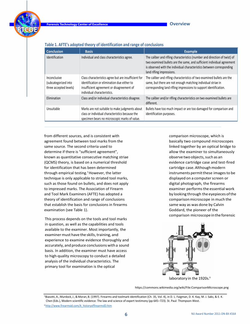
analysis of the individual characteristics. The
primary tool for examination is the optical
comparison microscope, which is
basically two compound microscopes
linked together by an optical bridge to
allow the examiner to simultaneously
observe two objects, such as an
evidence cartridge case and test-fired
cartridge case. Although modern
instruments permit these images to be
displayed on a computer screen or
digital photograph, the firearms
examiner performs the essential work
by looking through the eyepieces of the
comparison microscope in much the
same way as was done by Calvin
Goddard, the pioneer of the
comparison microscope in the forensic
laboratory in the 1920s.6
https://commons.wikimedia.org/wiki/File:ComparisonMicroscope.png
5 Biasotti, A., Murdock, J., & Moran, B. (1997). Firearms and toolmark identification (Ch. 35, Vol. 4), in D. L. Faigman, D. K. Kay, M. J. Saks, & E. K. Chen (Eds.), Modern scientific evidence: The law and science of expert testimony (pp 645–723). St. Paul: Thompson-West.
6 http://www.firearmsid.com/A_historyoffirearmsID.htm

7 NIJ Award Number 2011-DN-BX-K564
Overview
OVERVIEW OF FIREARM EVIDENCE SEARCH DATABASES
For many years, firearms examiners have used class
and individual characteristics on fired cartridge
cases and bullets to connect crimes in which the
firearm was initially unknown and therefore
unavailable for comparison. Computerized image
analysis enabled the automation of this process
and the construction of databases of firearm
evidence in shooting investigations and crime
guns starting in the late 1980s. In the late 1990s,
NIBIN became the standard tool in the United
States for databasing and comparing evidence and
crime guns. NIBIN’s effectiveness for comparing
cartridge cases and clearing firearm- related
homicides was demonstrated in the city of Boston.7
NIBIN is based on the Integrated Ballistic
Identification System (IBIS), which historically used
plan-view microscopic images to build its reference
collection and make comparisons. The comparisons
are limited to determining firearm types and
identifying possible firearms that may match crime
scene evidence. The system does not produce
identifications, which still rely on the examiner and
comparison microscope.
In 2008, the National Academy of Sciences
studied the possibility that a NIBIN-like system
could be used to establish a database of all guns
manufactured and sold.8 It concluded that such
a database was not feasible because current
microscopic and computer analytical methods
were insufficient to identify firearms
consistently in large databases.
TECHNOLOGY DEVELOPMENTS
Forensic tool mark examiners are the primary users
of the comparison microscope, although other
microscopic techniques have been developed that
may improve an examiner’s ability to discern tool
mark characteristics. In particular, optical
topography may address some of the limitations
inherent in traditional approaches, such as
depth-of-focus, specular reflection, and lack of
3D data. Some gun manufacturing techniques
(e.g., polygonal rifling, computer numerical
controlled [CNC] milling, and metal injection
molding [MIM]) add to the difficulty of making
comparisons in some cases.
The term, “optical topography” includes several
technical approaches, including focus variation,
confocal microscopy, interferometric-based
techniques, and photometric stereo. Systems cost
between $100,000 and $500,000, although
laboratories may take advantage of the Bureau of
Alcohol, Tobacco, Firearms, and Explosives’ NIBIN
program to defray some or all of the hardware
and network costs, subject to funding availability.
In focus variation, the in-focus plane of reflected
light is scanned in the z direction (vertical) to
provide a complete picture of an object. The
image is mathematically reconstructed by
combining multiple images—each with a very
shallow depth of focus—into a virtual 3D view.
Focus variation microscopes accommodate large
working distances, which may be convenient for
imaging the curved or deformed surface of a
bullet and steep edges such as those found in
firearms examination. When considering a focus
variation instrument, the laboratory should
consider vertical resolution carefully because
some lower priced instruments may not have the
resolution required for tool mark
Caption: focus variation
7 Linking Crime Guns: The Impact of Ballistics Imaging Technology on the Productivity of the Boston Police Department’s Ballistics Unit, J Forensic Sci, July 2004, Vol. 49, No. 4.
8 National Research Council. (2008). Ballistic imaging. D. L. Cork, E. S. Meieran, & C. V. Petrie (Eds). Washington, DC: The National Academies Press.
doi: 10.17226/12162
8 NIJ Award Number 2011-DN-BX-K564
Overview
examination. Alicona and Sensofar LLC have focus
variation microscopes for use in the forensic
laboratory. These instruments will provide good
lateral resolution.
In confocal microscopy, the examiner views an
image in which the incident and reflected light
from the object are always in focus. Light
passes through a pinhole aperture that blocks
out-of-focus light. In general, only one point is
illuminated at a time, but, in practice, either a
laser is scanned using mirrors—a laser
scanning confocal microscope—or white light
illumination is controlled using an array of
pinholes—a spinning (or Nipkow) confocal
microscope.
Confocal microscopy is the most common type
of optical microscopy in applications outside of
firearms identification, at least with respect to
the number of system vendors. Carl Zeiss AG,
Keyence Corporation, Leica, NanoFocus,
Olympus Corporation, Sensofar LLC, and Ultra
FTI all make confocal microscopes that could
be applied to firearms identification, although
the instruments vary with respect to
capabilities and ease-of-use for the examiner.
In general, confocal microscopes have larger
working distances, but this will depend on the
objective being used. As in other systems, a
confocal microscope using an objective lens
with a higher numerical aperture (NA) will have
lower working distance and higher maximum
measureable slope surface, while an objective
lens with a lower NA will have a higher
working distance and lower maximum slope
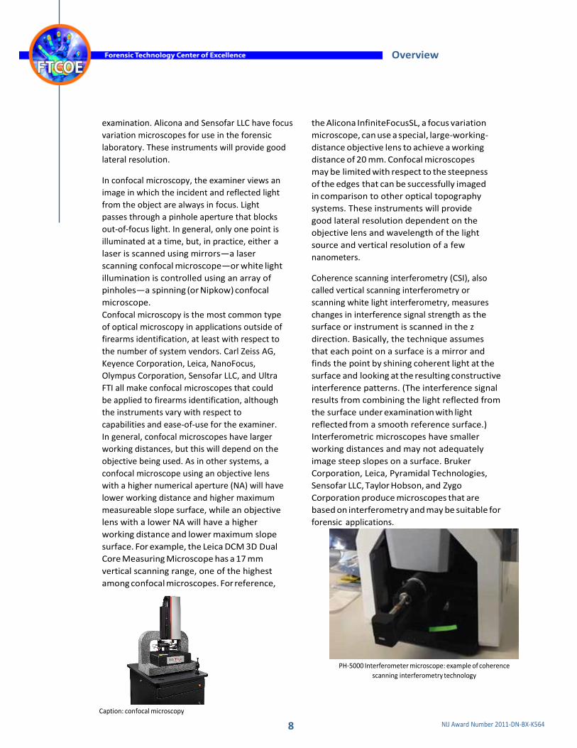
surface. For example, the Leica DCM 3D Dual
Core Measuring Microscope has a 17 mm
vertical scanning range, one of the highest
among confocal microscopes. For reference,
Caption: confocal microscopy
the Alicona InfiniteFocusSL, a focus variation
microscope, can use a special, large-working-
distance objective lens to achieve a working
distance of 20 mm. Confocal microscopes
may be limited with respect to the steepness
of the edges that can be successfully imaged
in comparison to other optical topography
systems. These instruments will provide
good lateral resolution dependent on the
objective lens and wavelength of the light
source and vertical resolution of a few
nanometers.
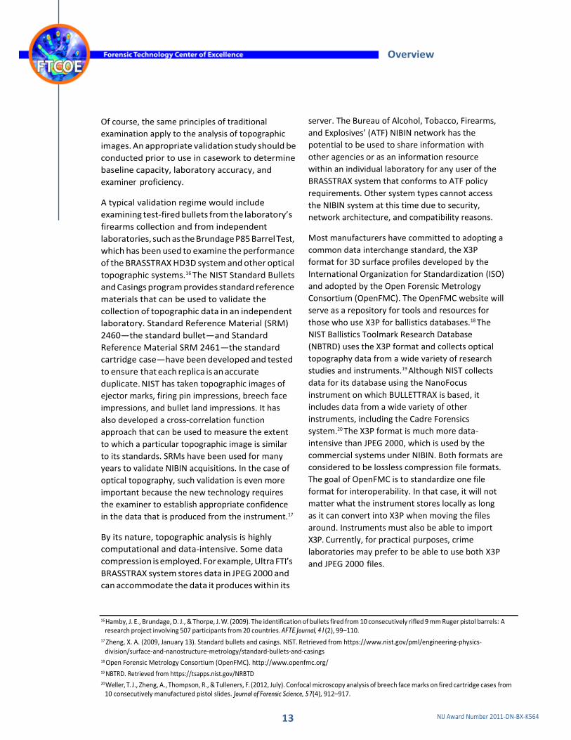
Coherence scanning interferometry (CSI), also
called vertical scanning interferometry or
scanning white light interferometry, measures
changes in interference signal strength as the
surface or instrument is scanned in the z
direction. Basically, the technique assumes
that each point on a surface is a mirror and
finds the point by shining coherent light at the
surface and looking at the resulting constructive
interference patterns. (The interference signal
results from combining the light reflected from
the surface under examination with light
reflected from a smooth reference surface.)
Interferometric microscopes have smaller
working distances and may not adequately
image steep slopes on a surface. Bruker
Corporation, Leica, Pyramidal Technologies,
Sensofar LLC, Taylor Hobson, and Zygo
Corporation produce microscopes that are
based on interferometry and may be suitable for
forensic applications.
PH-5000 Interferometer microscope: example of coherence
scanning interferometry technology

9 NIJ Award Number 2011-DN-BX-K564
Overview
Finally, photometric stereo microscopes are
based on the idea that the amount of light
reflected from a surface depends on its
orientation, so a 3D surface topography can
be derived from the light pattern. The
technique depends on the uniformity of the
surface. In the Cadre Forensics Gelsight
instrument, a painted gel is used to make an
impression of the cartridge case under
examination, and the microscope images the
paint, not the case itself. This produces a
remarkably accurate topographic
representation of the surface under
examination. The Cadre Forensics instrument
is under development for firearms
examination applications and has been funded
by the National Institute of Justice’s (NIJ)
research grant program.9
There are other approaches, including scanning
electron microscopy (SEM) or stylus profilometry,
but, in general, these methods are not used in
firearms identification in the crime laboratory.
SEM has been used in Europe and the U.S. Fish
and Wildlife Service Forensics Laboratory. Stylus
profilometry is a contact method that may
damage the sample, a significant drawback in the
forensic laboratory.
TopMatch-GS 3D Version 2 Scanner: example of photometric stereo
technology
INSTRUMENT OVERVIEW
In this landscape report, we present options
for the forensic laboratory in selecting optical
topography imaging systems. Although we
initially contacted a very wide range of
vendors to participate with the Forensic
Optical Topography Working Group, only a
subset chose to do so. We contacted all of the
interested vendors to solicit information
about their systems for this report.
Table 2 provides a summary of currently available
instruments from responding vendors. We
surveyed instrument manufacturers concerning
the performance of their systems on a wide
variety of parameters. The manufacturer chose
the model to be included here. Of course, there
will be variation among models with respect to
operational parameters. Table 2 and the more
detailed table presented in Appendix A are based
on those industry self-reports. In some cases,
manufacturers reported information that is
subject to interpretation. All claims should be
subject to verification if a laboratory is
considering a purchase.
Currently, there are no standardized performance
evaluation tests for optical topography
instruments for use by firearms examiners. The
National Institute of Standards and Technology
(NIST)10 maintains bullet and casing standards, but
these do not provide a basis for evaluating the
performance of all aspects of these microscopes,
such as lateral resolution, maximum measureable
slope, and stitching (i.e., the ability to combine
multiple images into one view of surface
topography). NIST is developing appropriate
approaches to these problems. Until then, it may
be difficult to compare instrument performance
among manufacturers, verify instrument
performance, calibrate or address instrument
performance, assess quality, and validate a
laboratory’s ability to perform optical topography
reliably.
9 Law Enforcement’s Silent Partner: Forensics Research and Development, Police Chief Volume:81 Dated:October 2014 Pages: 32 to 38 10 NIST — http://www.nist.gov/forensics/ballisticsdb

10 NIJ Award Number 2011-DN-BX-K564
Overview
Table 2. Brief overview of currently available instruments from responding vendors
Manufacturer Alicona Cadre Research Labs
Leica Microsystems
Pyramidal Technologies
ScannBi Technology USA
Sensofar LLC Ultra FTI
Model InfiniteFocus
InfiniteFocus SL (SL)
TopMatch-GS 3D
Leica DCM8 PH-5000 Interferometer
Evofinder 4x4 S Neox IBIS TRAX- HD3D
BULLETTRAX
IBIS TRAX-HD3D BRASSTRAX
Instrument Type
Confocal x x x
Interferometry x x x
Focus variation x x x x
Photometric stereo x x
3D reconstruction x
Data
Data management Local data only
TopMatch software includes DB using correlation functionality
Local data only
Advanced search with customizable filtering
Database search using correlation analysis of exhibits and test fires
Local data only
Historical crime-related exhibits and test fires
Exchange Standards
X3P Included Included Included Option Planned Option Planned
Cartridge Case Image Time (9 mm)
Full breech face < 5 min 10–20 secs 5 min
Primer area only Resolution- dependent
< 2 min Far less than 5 min ~30 sec 10–20 secs for three fields of view
N/A
Security
Security ISA 27001; NIST SP 800-53
Estimated Cost (varies based on configuration)
ATF NIBIN (ATF)
$$ (SL $-$$)
$
$$
$-$$$
$$-$$$
$$
ATF $$
< $100,000 ($)
$100,000–500,000 ($$)
> $500,000 ($$$)
Users
Crime Laboratories Yes, state, local, and federal labs
State of Colima (Mexico)
Several countries in Europe, Brazil, Morocco, and the U.S.
ADFS-Derrick McClarin, FBI
State and local labs, ATF-Atlanta
State & local, ATF, U.S. Customs & Border Patrol, FBI-Quantico
Other Yes, research labs
Dom Rep (SISNA/LABBS); Huddersfield Uni., UK; EU Odyssey Proj.
Lausanne Technical University
More than 600 systems deployed worldwide
More than 140 units deployed worldwide
More than 220 units deployed
Table information is based on vendor input that is subject to interpretation and verification.

Overview
11 NIJ Award Number 2011-DN-BX-K564
EFFECTIVE USE OF OPTICAL TOPOGRAPHIC MICROSCOPE
Optical topography can be a powerful
complement to existing methods for the
firearms examiner, but the particular place of the
instrument in the examination work flow should
be well established prior to its deployment in the
laboratory. The instrument may be used in
several ways, including to:
▪ build and search a reference database to find
the source of a bullet or cartridge case from a
crime scene;
▪ serve as a complement to the comparison
microscope, especially for difficult
comparisons;
▪ supplement image data taken from the
comparison microscope to document a
comparison that has been completed;
▪ clarify the basis on which an examiner has
made a particular comparison decision; and
▪ make comparison decisions.
The laboratory should maintain a protocol that
determines when optical topography is to be used
and the procedures for each application. Some
systems are designed to perform one particular
task. For example, Ultra FTI’s BRASSTRAX™ system
is specifically designed as a reference database
tool for cartridge cases.
In the future, optical topography may be used
to provide a quantitative match probability for
comparisons, but further research is required
to put this concept into practice.
Additionally, because these instruments are
measuring devices, calibration and performance
checks are required to obtain accurate surface
acquisitions. Traceable surface standards for such
calibrations may not be familiar to examiners new
to this technology. They would require additional
training for accurate use.
Theoretically, optical topography systems may
complement or even replace comparison
microscopes in the future. Comparison
microscopy is limited with respect to the
number of perspectives that can be clearly
viewed by the examiner, while computer-
based image analysis enables rapid review of
almost any orientation of a bullet or casing,
thus facilitating a “virtual reality” view of the
surface. Although the comparison
microscope has been proven in the
forensics community for nearly a century,
the extent to which limitations of human
visual perception and visuospatial cognition
may affect examinations is unknown. In
contrast, optical topography permits a
completely independent review of the exact
same data by multiple examiners and the
presentation of the basis of identification
decisions in detailed images. Further, optical
topographic data can be quantitatively
evaluated to produce a probabilistic
interpretation of identification decisions,
although research is still needed to enable
such an advance.
Current analytical techniques may provide an
imperfect measure of error rates, and algorithms
do not necessarily capture all of the information
contained in complex striated or impressed
tool marks.11
Current automated systems permit more efficient
comparison decisions that may be useful to
produce leads in a “forensic intelligence”
framework. In these programs, the intent is to
provide investigators with leads and linkages
among crime scenes. It must be understood that
the evidence that produces the leads must
ultimately be subject to analysis using traditional
comparison microscopy before use in trial
proceedings.
There are some concerns that optical topographic
systems may introduce unknown artifacts into
image data that could skew interpretation. At this
time, examiners should expect to rely on the
11 Petraco, N. D. D., Chan, H., De Forest, P. R., Diaczuk, P., Gambino, C., Hamby, J.,…Shenkin, P. (2012, July). Application of machine learning to toolmarks:
Statistically based methods for impression pattern comparisons. U.S. Department of Justice.

Overview
12 NIJ Award Number 2011-DN-BX-K564
comparison microscope for several reasons. First,
the comparison microscope has been in use
worldwide for many decades, so there is a good
understanding of its capabilities and limitations
within the forensics community as well as the
broader police and legal communities. Also, there
are well-established training regimes to produce
an expert tool mark examiner who relies on the
comparison microscope, but there is nothing
comparable for optical topography methods.
Finally, examiners and scientists do not yet have a
systematic understanding of the artifacts, outliers,
dropouts, or other imperfections in topographic
images that may lead to erroneous identification
decisions. For example, optical topographic
instruments may vary with respect to how well
they stitch together images to create a complete
view of a surface’s topography or with respect to
their ability to accurately collect data from steep
slopes on a sample’s surface.
Some laboratories have used optical
topography systems to build reference
collections and make “cold” hits between
firearms and evidence collected in shooting
investigations. Two instruments, the IBIS®
TRAX-HD3D™ (based on the BRASSTRAX
imaging system) and the ScannBi “Evofinder,”
have software that facilitates this function.
The former system is tied to NIBIN and
available through that program or directly
from the vendor. Evofinder has been installed
in a few sites in the United States but has a
larger presence in European crime
laboratories. In general, laboratories have
found that optical topography-based
systems are superior to prior- generation
image microscopy systems (e.g., so-called
“heritage IBIS” systems) with respect to the
likelihood that an accurate match is made in a
database search and that the accurate match
ranks highly among the list of possible matches
from a search.12,13 Further information about
optical topography’s use as a tool for firearm
evidence collection construction is provided
below.14,15
OPERATIONAL CONSIDERATIONS
Confocal microscopy and similar systems
have existed for decades primarily in surface
measurement and medical diagnostics, but
current systems surpass older confocal
microscopes with respect to ease of use
and the extent to which they are adapted
to firearms identification. Unlike older
systems, the majority of current optical
topography systems do not require special
environments or optical tables to limit
vibration and obtain useful images. Most
vendors specify an office-like environment.
In some research and operational facilities,
the systems have been deployed on optical
tables in basement laboratories with
environmental controls. Since such
requirements could add to the logistical and
financial burden, the potential user should
consult with the vendor concerning
specific installation and environmental
requirements.
Training is limited to that provided by
manufacturers. Some vendors provide substantial
training upon installation in the operation of the
instrument, and the majority will provide enough
training to permit the use of the instrument in
database searches. If the laboratory intends to use
optical topography in casework as a complement
to comparison microscopy, it is important to
understand that little to no specialized training
currently exists to support that type of practice.
12 The reference ballistic imaging database revisited, Jan De Ceuster, Sylvain Dujardin, Forensic Science International, 248 (2015) 82-87. 13 Reconsidering the Ballistic Imaging of Crime Bullets in Gun Law Enforcement Operations, Anthony Braga and Glenn Pierce, Forensic Science
Policy & Management: An International Journal, 2:3, 105-117. 14 Vorburger, T. V., Yen, J. H., Bachrach, B., Renegar, T. B., Ma, L., Rhee, H-G.,…Foreman, C. D. (2007, May 1). Surface topography analysis for a
feasibility assessment of a national ballistics imaging database. Gaithersburg, MD: NIST. 15 Chu, W., Song, J., Vorburger, T., Yen, J., Ballou, S., & Bachrach, B. (2010, March 1). Pilot study of automated bullet signature identification based on
topography measurements and correlations. Journal of Forensic Science, 55(2), 341–347. doi: 10.1111/j.1556-4029.2009.01276.x.
Overview
13 NIJ Award Number 2011-DN-BX-K564
Of course, the same principles of traditional
examination apply to the analysis of topographic
images. An appropriate validation study should be
conducted prior to use in casework to determine
baseline capacity, laboratory accuracy, and
examiner proficiency.
A typical validation regime would include
examining test-fired bullets from the laboratory’s
firearms collection and from independent
laboratories, such as the Brundage P85 Barrel Test,
which has been used to examine the performance
of the BRASSTRAX HD3D system and other optical
topographic systems.16 The NIST Standard Bullets
and Casings program provides standard reference
materials that can be used to validate the
collection of topographic data in an independent
laboratory. Standard Reference Material (SRM)
2460—the standard bullet—and Standard
Reference Material SRM 2461—the standard
cartridge case—have been developed and tested
to ensure that each replica is an accurate
duplicate. NIST has taken topographic images of
ejector marks, firing pin impressions, breech face
impressions, and bullet land impressions. It has
also developed a cross-correlation function
approach that can be used to measure the extent
to which a particular topographic image is similar
to its standards. SRMs have been used for many
years to validate NIBIN acquisitions. In the case of
optical topography, such validation is even more
important because the new technology requires
the examiner to establish appropriate confidence
in the data that is produced from the instrument.17
By its nature, topographic analysis is highly
computational and data-intensive. Some data
compression is employed. For example, Ultra FTI’s
BRASSTRAX system stores data in JPEG 2000 and
can accommodate the data it produces within its
server. The Bureau of Alcohol, Tobacco, Firearms,
and Explosives’ (ATF) NIBIN network has the
potential to be used to share information with
other agencies or as an information resource
within an individual laboratory for any user of the
BRASSTRAX system that conforms to ATF policy
requirements. Other system types cannot access
the NIBIN system at this time due to security,
network architecture, and compatibility reasons.
Most manufacturers have committed to adopting a
common data interchange standard, the X3P
format for 3D surface profiles developed by the
International Organization for Standardization (ISO)
and adopted by the Open Forensic Metrology
Consortium (OpenFMC). The OpenFMC website will
serve as a repository for tools and resources for
those who use X3P for ballistics databases.18 The
NIST Ballistics Toolmark Research Database
(NBTRD) uses the X3P format and collects optical
topography data from a wide variety of research
studies and instruments.19 Although NIST collects
data for its database using the NanoFocus
instrument on which BULLETTRAX is based, it
includes data from a wide variety of other
instruments, including the Cadre Forensics
system.20 The X3P format is much more data-
intensive than JPEG 2000, which is used by the
commercial systems under NIBIN. Both formats are
considered to be lossless compression file formats.
The goal of OpenFMC is to standardize one file
format for interoperability. In that case, it will not
matter what the instrument stores locally as long
as it can convert into X3P when moving the files
around. Instruments must also be able to import
X3P. Currently, for practical purposes, crime
laboratories may prefer to be able to use both X3P
and JPEG 2000 files.
16 Hamby, J. E., Brundage, D. J., & Thorpe, J. W. (2009). The identification of bullets fired from 10 consecutively rifled 9 mm Ruger pistol barrels: A research project involving 507 participants from 20 countries. AFTE Journal, 41(2), 99–110.
17 Zheng, X. A. (2009, January 13). Standard bullets and casings. NIST. Retrieved from https://www.nist.gov/pml/engineering-physics-
division/surface-and-nanostructure-metrology/standard-bullets-and-casings 18 Open Forensic Metrology Consortium (OpenFMC). http://www.openfmc.org/ 19 NBTRD. Retrieved from https://tsapps.nist.gov/NRBTD 20 Weller, T. J., Zheng, A., Thompson, R., & Tulleners, F. (2012, July). Confocal microscopy analysis of breech face marks on fired cartridge cases from
10 consecutively manufactured pistol slides. Journal of Forensic Science, 57(4), 912–917.

Overview
14 NIJ Award Number 2011-DN-BX-K564
CONSIDERATIONS IN THE SELECTION OF OPTICAL TOPOGRAPHIC MICROSCOPES
Thus far, only a limited number of laboratories
have procured optical topographic microscopes,
and even fewer have applied them to actual
casework. NIST has studied optical topography
extensively for application to firearms
identification. It has established a foundation for
collection and data analysis that is based on the
fundamental advantage of optical topography:
the ability to provide detailed topography images
of surfaces. The components of surface
topography include roughness, waviness, surface
irregularity, and flaws or imperfections.
Topographic microscopy can measure roughness
directly, independent of illumination and
shadowing effects, but with some limitations.
The standards for each consideration are laid out
in detail in ISO Draft International Standard
25178-6,21 which includes several individual
documents for different types of topographic
instruments. It is not necessary for a user to be
able to apply the ISO document independently,
but a vendor of a topographic microscope should
be able to reference the performance of a
particular systems against parameters in the ISO
standard, including those in Table 3.
Table 3. ISO standard parameters and questions for measurement
Parameter Definition Typical question
Instrument type Type of optical topography instrument Is it focus variation, confocal, interferometry, or photometric stereo?
Other instrument aspects
Subtype and constraints What is the magnification of the types of objective lenses that are available?
Sample mount Does the system require special mounting or media (e.g., water immersion or the use of a gel)?
Forensic application Has the system been designed for reference collection databases, cold hit searches, and/or as a complement to comparison microscopy in casework?
Reference databasing Database search capability Can the system collect and search a reference collection?
Spatial (lateral) Smallest lateral 3D structure that can be What is the smallest lateral 3D feature that the microscope can resolution resolved measure?
Lateral range Largest lateral measurement range the instrument can measure
What is the maximum lateral measurement range?
Bandwidth limits Spatial resolution and longest measureable spatial wavelength
What is the range between the smallest and largest features?
Vertical resolution Smallest height variations that can be assessed with the instrument
What is the smallest step that will be detected?
Vertical range Largest height variation that can be assessed
What is the tallest feature this instrument can measure?
Dynamic range
Working distance The distance between the microscope objective and the sample
How close does the objective come to the surface? Can images of complex geometries be collected without making contact with the sample?
Vertical scanning resolution
Linearity and reproducibility of the scanning stage
Does the scanning stage limit my ability to reliably measure vertical steps?
21 ISO 25178-6:2010 — Geometrical product specifications (GPS) — Surface texture: Areal — Part 6: Classification of methods for measuring
surface texture (http://www.iso.org/iso/iso_catalogue/catalogue_tc/catalogue_detail.htm?csnumber=42896)

Overview
15 NIJ Award Number 2011-DN-BX-K564
Table 3. ISO standard parameters and questions for measurement (continued)
Parameter Definition Typical question
Pixel size The lateral size of one pixel of the imaging array on a surface
What is the smallest feature that can be imaged (generally higher than spatial resolution)?
Maximum slope The steepest slope that can be reliably imaged
What are the highest surface slopes that this instrument can image without dropouts or outliers (objective-NA-dependent)?
Typical measurement time
Seconds to capture a full field of view How long does it take to capture a single measurement?
Typical data Minutes to capture a sample of bullet land, How long does it take to capture a complete image, including collection time firing pin, and breech face mounting and setting up the bullet or cartridge case?
Facility requirements Temperature, humidity control, power, and stability
Does the instrument need to be placed in a dry environment or on an optical table/in a basement laboratory?
There are tradeoffs for any instrument with respect to these parameters. For example, focus variation
instruments have very good vertical range (i.e., they can measure steeply sloped surfaces). On the other
hand, they may not attain the vertical resolution of other instruments.
16 NIJ Award Number 2011-DN-BX-K564
1 Overview
17 Use Cases
21 State of the Market
25 Glossary
31 Detailed Product Specifications

17 NIJ Award Number 2011-DN-BX-K564
Use Cases
USE CASES
This section provides examples of successful implementation of optical topography technology
to illustrate benefits and key adoption issues. The use cases offer insight on different ways that the
technology has been an effective tool within law enforcement and a crime laboratory. Key
impacts and lessons learned are highlighted.
ORANGE COUNTY, CALIFORNIA Orange County California
Contributor
Tara Heye, Senior Forensic Scientist, Orange County
Crime Laboratory
User Profile
Orange County, California has a population of 3 million people,
making it the sixth most populous county in the United
States. Its ballistics unit employs five examiners. It employed
NIBIN Heritage for 12 years and generated approximately
100 hits, of which two were confirmed hits outside of Orange
County. It stopped entering bullets into NIBIN in 2008
because it had not achieved any hits from that work, which
had poor image quality. After losing its NIBIN system in 2013,
Orange County established the Orange County Ballistic Unit
Local Law Enforcement 3D Technology (OCBULL3T) system
using Evofinder.22 Evofinder is a focus variation system that
reconstructs 3D topography from multiple 2D images. This
approach is sometimes called “2D+D.” OCBULL3T includes
bullets and cartridge cases from evidence and test fires from
2013 to the present, covering 1,260 cases, 1,300 cartridge
cases, and 1,650 bullets. Orange County has generated 56
confirmed total hits, including 43 cartridge case cold hits and
13 bullet hits, including 3 from pistols and 4 from revolvers.
Two of the pistol hits were based only on bullets.
Validation and Implementation
Orange County conducted a validation of the Evofinder system using currently available methods,
including test-fired bullets from consecutively rifled barrels (based on the Brundage 10 Barrel Test),
and both bullets and cartridge cases generated from its firearms collection. The entire test-fired
data set included 76 items, including at least 2 test fires from each firearm. As stated previously in
this report, there is no accepted method to validate optical topography instruments for forensic
comparison purposes because of the lack of performance measurement standards. In Orange
County’s
22 2D+D. (2016). Evofinder. Retrieved from http://evofinder.com/technology/2dd/
Key Impacts and Lessons Learned 1. The number of hits has increased
dramatically from 5 in the first 2 years with NIBIN Heritage to 50 with Evofinder (OCBULL3T).
2. OCBULL3T success has produced an increase in firearms work request submissions. The current backlog is ~600 cases (an approximately 10-fold increase).
3. The increase in hits and firearms submissions was difficult to foresee; crime lab management is actively working on increasing trained staff to respond to the increase.
4. The dramatic increase in hits appears to be the result of correlation using the 3D reconstruction data sets provided by Evofinder.

18 NIJ Award Number 2011-DN-BX-K564
Use Cases
examination of consecutively rifled barrels from the Brundage study, staff did not observe an instance
in which an unrelated bullet ranked higher than duplicate or “sister” images. For virtual microscopy
validation, the Orange County Crime Lab selected firearms that produce test fires that are difficult to
identify using comparison microscopy. Staff analyzed test fires using comparison microscopy and the
Evofinder system, and used a scanning electron microscope as a “ground truth” validation of individual
impressions, such as striae. Overall, 92% of breech face and firing pin correlations ranked very high—
either first or second—in the match list, although the database was limited. Interestingly, the Evofinder
search produced accurate matches even in cases when an examiner using a comparison microscope
could not make an identification.
Orange County has applied the Evofinder to casework in both cartridge cases and bullets as a
complement to comparison microscopy, although staff have found that optical topographic image
data is superior. At this time, they rule out any conclusion based on the Evofinder if the match cannot
be made using the comparison microscope. In this case, even a clear Evofinder match would be ruled
“inconclusive.” In reporting such instances, staff state that the images “suggest an identification.”
In other words, the comparison microscope is still the standard by which the laboratory makes
forensic comparisons.
19 NIJ Award Number 2011-DN-BX-K564
Use Cases
NEW JERSEY STATE POLICE
Contributors
The New Jersey State Police (NJSP) has long used NIBIN to link
firearms to crime scenes. Nonetheless, NJSP sees high rates of
gun crime, especially along the Route 21 corridor. In the past,
it took an average of 10 months for a crime gun to make it into
NIBIN. In some cases, it took up to 2 years. Given that the “time
to crime”—the amount of time from legitimate sale to the use
of a gun in crime—is often shorter than the 2 year timeframe,
it became imperative to improve the use of ballistics evidence
to get any investigative value.
In accordance with a state statute and under the leadership
of NJSP’s Superintendent, Colonel Rick Fuentes, New Jersey’s
800 law enforcement agencies took a new approach.
Administrative and policy choke points were identified and
new processes established to facilitate the rapid turnaround of
evidence. Now, police agencies expeditiously submit all crime
guns for inclusion into NIBIN. The evidence is prioritized and
uploaded into NIBIN quickly.
NJSP’s process reforms were enabled by the technological revolution of optical topography. Older,
“heritage” NIBIN systems were based on 2D images of cartridge cases and bullets, but newer systems
now obtain high-resolution, 3D data. The difference in image quality produces an astounding difference
in the ability to identify an unknown firearm in a reference database quickly and accurately. The Bureau
of Alcohol, Tobacco, Firearms, and Explosives (ATF) has deployed data “concentrators” to ingest this data
across the country, with the goal of enabling rapid database searching across jurisdictional boundaries
and development of early casework leads from ballistic evidence.
The NJSP Real-time Crime Center uses ballistic evidence in combination with other types of information
about suspects, trends, and other forensic intelligence. Staff gathered over 1,000 hits in Newark—an
astounding number that changes the entire dynamic of the investigation of violent crime.
Key Impacts and Lessons Learned 1. Optical topography and advanced data
analysis enable the rapid turnaround of case hits to enable investigative leads and crime scene linkages.
2. The BRASSTRAX system and ATF network provide a seamless capability for finding hits across jurisdictional boundaries.
3. Executive leadership can enable more efficient use of firearms identification data through the development of processes that prioritize evidence and eliminate policy choke points.

20 NIJ Award Number 2011-DN-BX-K564
1 Overview
17 Use Cases
21 State of the Market
25 Glossary
31 Appendix A

State of the Market
21 NIJ Award Number 2011-DN-BX-K564
STATE OF THE MARKET
Although several manufacturers have developed optical topography instruments that may be useful
in firearm identification, the vast majority of systems deployed in crime laboratories are BrassTrax
systems from Ultra FTI. These instruments are compatible with the ATF’s NIBIN program, thus
permitting information sharing and leveraging of ATF investments in network architecture and
systems. ATF supports the purchase and maintenance of the Ultra FTI instruments in some cases,
and will support the connection of the Ultra FTI instruments to NIBIN for any laboratories that
purchase the systems on their own. Ultra FTI provides instruments only to laboratories that
participate in NIBIN.
Currently, ATF does not permit instruments from
other manufacturers to access NIBIN. Theoretically,
any data produced by other instruments could be
output into the standard JPEG 2000 image
compression format and uploaded into NIBIN. In
practice, that does not occur. Ultra FTI instruments
are currently the only instruments that meet the
rigorous data security requirements of ATF’s NIBIN
network.
There is very little data concerning the relative
performance of competing systems with respect
to image fidelity, efficiency of their database
searching algorithms, or other parameters of
operational interest. This report recommends
that such studies be performed in the context of
improving understanding of the fundamental
performance of optical topography as a tool for
the firearms examiner.
FUTURE OF OPTICAL TOPOGRAPHY IN FIREARM IDENTIFICATION
Optical topography presents a major opportunity
to improve the practice of firearm identification in
a manner that is similar in impact to DNA
technology for human identification. As of this
writing, the adoption of optical topography in
firearm identification is in its early stages. Thus far,
forensic science laboratories have adopted optical
topography primarily as an upgrade to their
existing systems for database searching.
Others are using the technology to augment their
examinations from comparison microscopy. Few
laboratories are using the full range of the
systems’ capabilities. It is difficult to foresee the
changes that may arise from further
development of the technology and more
widespread use.
To date, NIJ has funded extensive work in
the development of systems and improved
understanding of the topographic
metrology of ballistic evidence.23 The
Forensic Optical Topography Working
Group examined the state of optical
topography and developed several
recommendations to address adoption
issues in forensic practice. Several of the
recommendations focus on research and
development of key issues. Other
recommendations address shortfalls in
training and practice.
▪ Improve data sets and the understanding
of similarities and differences among
firearms, particularly with respect to
consecutively manufactured firearms,
mark persistence, and firearms that
present identification challenges. NIST and
the Federal Bureau of Investigation (FBI)
have pursued this research jointly to build
the NIST Ballistics Toolmark Research
Database. The work complements the view
that optical topography may elucidate
issues related to difficult match
comparisons that are not easily amenable
23 For examples of extensive funding, please see https://www.ncjrs.gov/pdffiles1/nij/grants/232136.pdf,
https://www.ncjrs.gov/pdffiles1/nij/grants/248962.pdf, and https://www.ncjrs.gov/pdffiles1/nij/grants/248639.pdf.

State of the Market
22 NIJ Award Number 2011-DN-BX-K564
to traditional comparison microscopy. More fundamentally, characterization of the NBTRD could contribute to the scientific basis for firearms identification. This process may also contribute to the development of validation and operating procedures. ▪ Establish validation, methods, best
practices, certification, and training for
firearms examiners using optical
topography in practice. Firearms examiners
receive extensive formal and informal
training to use the comparison microscope
and complementary methods to make
comparisons in current practice. AFTE has
established programs to promulgate accepted
methods and train and certify examiners.
Thus, the field is organized around a very
effective set of practices and technology. No
comparable foundation exists to establish and
promulgate methods related to the
application of optical topography, except the
training provided by instrument
manufacturers in the operation of their
systems. The NIST Organization of Scientific
Area Committee’s (OSAC) Firearms and Tool
Marks Subcommittee has begun to establish
validation, methods, and training to support
optical topography. Additional support will
be needed to turn these methods into
guidance and training for the field.
▪ Examine factors that improve
database searching using optical
topography. As stated previously,
there are several ways in which a
laboratory could apply this new
technology in practice. Currently,
laboratories use it as a tool to
improve database searches as a
simple substitute for less capable
microscopes. Studies indicate that
database searches are greatly
improved when using optical
topography,24 but there is limited
evidence with regard to related
factors, such as firearm type,
search algorithm, operational
constraints, or instrument type. For example,
some instruments use search algorithms that
are designed to take advantage of
topographic data and may present an
opportunity to improve the speed and
reliability of searches. Studies should include
controlled sets of firearms, operational
evaluations to examine implications in
practice, and consideration of various
algorithmic approaches to improve the
efficiency of searches. Anecdotally,
practitioners report that interjurisdictional
hits are enabled by the use of topographic
data. Research is needed to confirm this
assertion and determine factors that enable
effective interjurisdictional searching.
▪ Improve the understanding of the impact of
the application of optical topography in the
laboratory. Evidence prioritization and
improved process flow could enable broader
use to improve the investigation of gun
crime, as in New Jersey. Further, rapid
presumptive identification could be
leveraged to produce cold hits early in
investigations, an approach that leverages
ATF’s substantial investment in the national
data concentrator infrastructure. This is only
possible because of the improvement in
image quality and visualization in current
systems such as BRASSTRAX HD3D. Finally,
the new systems may improve the ability of
examiners to review difficult comparisons as a
complement to the comparison microscope.
Ultimately, this may lead to broader use
of optical topography in the examination
and comparison process itself. Operational
evaluations in firearms laboratories are
needed to understand the effectiveness
and impact of these novel operational
approaches so that they can be
promulgated across the criminal justice
community with research-based best
practices. Operational evaluations
should include multiple platforms,
including systems emerging from
24 Jan De Cuester and Sylvain Dujardin, The reference ballistic imaging database revisited, Forensic Science International, 248 (2015) 82-87.

23 NIJ Award Number 2011-DN-BX-K564
State of the Market
interlaboratory comparisons, data
exchange research and development,
depending on the operational readiness
of the systems to meet practitioner
requirements.
▪ Improve interoperability of instruments
and databases across laboratories. Several
instruments have the capability to collect
detailed and accurate data for use in ballistic
comparisons. That said, interoperability
depends on several factors, including
standards, data security, and related issues.
In particular, the X3P data interchange
standard could enable operational
cooperation among law enforcement
agencies and data interchange, if it
becomes a standard feature of all optical
topography systems. NIST, in collaboration
with government laboratories and
researchers, is in the process of an
interlaboratory study on interoperability
currently. Initial results are expected in
mid-2017.
Forensic scientists have become more aware of
the need for rigorous evaluation and validation
prior to the use of a new method or technology,
in part because of the overarching review of
forensic practice by the National Academy of
Sciences.25 Further research, development, and
evaluation can provide a foundation that should
permit firearms examiners to take advantage of
the promise of optical topography and avoid
pitfalls from the use of invalidated or poorly
understood methods.
25 National Research Council. 2009. Strengthening Forensic Science in the United States: A Path Forward. Washington, DC: The National Academies
Press. doi: 10.17226/12589.

24 NIJ Award Number 2011-DN-BX-K564
1 Overview
17 Use Cases
21 State of the Market
25 Glossary
31 Detailed Product Specifications
25 NIJ Award Number 2011-DN-BX-K564
Glossary
GLOSSARY OF COMMONLY USED WORDS AND PHRASES
This glossary was built using various resources, with the following three references adding
significant value.
AFTE (2013). Association of Firearm and Tool Mark Examiners glossary (6th ed.). Version 6.120414.
Thompson, R. M. (2010). Firearm identification in the forensic science laboratory. National District
Attorneys Association. Retrieved from http://www.ndaa.org/pdf/Firearms_identity_NDAAsm.pdf
Vorburger, T. V., Song, J., & Petraco, N. (2015, December 17). Topography measurements and applications
in ballistics and tool mark identifications. Surface Topography: Metrology and Properties, 4(1).
Action: The working mechanism of a firearm.
Automatic—A firearm design that feeds cartridges, fires, extracts, and ejects cartridge cases as long as the trigger is fully depressed and there are cartridges in the feed system. Also called “full auto” and “machine gun.”
Bolt—A firearm mechanism in which the breech closure
1. is in line with the bore at all times;
2. manually reciprocates to load, unload, and cock; and
3. is locked in place by breech bolt lugs and engages abutments usually in the receiver. There are two principal types of bolt actions: the turn rotating bolt and the straight pull.
Lever—A design wherein the breech mechanism is cycled by an external lever, generally configured below the receiver.
Revolver—A firearm, usually a handgun, with a cylinder having several chambers so arranged as to rotate around an axis and be discharged successively by the same firing mechanism.
Semiautomatic—A repeating firearm requiring a separate pull of the trigger for each shot fired, and which uses the energy of discharge to perform a portion of the operating or firing cycle (usually the loading portion).
Slide—An action that features a movable forearm which is manually actuated in a motion parallel to the barrel by the shooter. Forearm motion is transferred to a breech bolt assembly that performs all of the functions of the firing cycle assigned to it by the design.
AFTE: Association of Firearm and Tool Mark Examiners, the international professional organization for practitioners of firearm and/or tool mark identification, dedicated to the exchange of information, methods, and best practices, and the furtherance of research since its creation in 1969.
Breech face: The part of the breechblock or breech bolt that is against the head of the cartridge case or shotshell during firing.
Bullet: A nonspherical projectile for use in a rifled barrel.
Cartridge: A single unit of ammunition comprising the case, primer, and propellant with one or more projectiles. Also applies to a shotshell.
Cartridge, center fire: Any cartridge that has its primer central to the axis in the head of the case.

26 NIJ Award Number 2011-DN-BX-K564
Glossary
Cartridge, rim fire: A flange-headed cartridge containing the priming mixture inside the rim cavity.
Cartridge case: The container for all other components of a cartridge.
Chamber: The rear part of the barrel bore that has been formed to accept a specific cartridge. Revolver cylinders are multi- chambered.
Chamber marks: Individual microscopic marks placed on a cartridge case by the chamber wall as a result of any or all of the following: chambering, expansion during firing, or extraction.
Class characteristics: Measurable features of a specimen that indicate a restricted group source. They result from design factors and are therefore determined prior to manufacture.
Coherence scanning interferometric microscope: An optical microscope that produces a topographic image from the interference between light reflected from the surface under study and light reflected from a reference surface.
Comparison microscope: Two microscopes tied together by an optical bridge to allow an examiner to simultaneously observe two objects, such as a questioned cartridge case from a crime scene and one from a test-fired cartridge case from a submitted firearm, side by side in the same field of view. Although modern instruments permit these images to be displayed on a computer screen or photograph, the essential work is done by the expert firearms examiner peering through the eyepieces of the comparison microscope.
Confocal microscope: An optical microscope that uses a pinhole to eliminate out-of-focus light from an image and permits the reconstruction of a topographic, three-dimensional (3D) view of an object by combining images from multiple focal planes. Types of confocal microscopes include laser scanning confocal microscopy, disk scanning confocal microscopy (including Nipkow disk scanning), and programmable array microscopy.
Ejector: A portion of a firearm’s mechanism that ejects or expels cartridges or cartridge cases from a firearm.
Extractor: A mechanism for withdrawing the cartridge or cartridge case from the chamber.
FTCOE (http://www.forensiccoe.org/): A collaborative partnership providing testing, evaluation, and technology assistance to forensic laboratories and practitioners in the criminal justice community. This partnership is led by RTI International (http:// www.rti.org/), and funded by the National Institute of Justice.
Firearm: An assembly of a barrel and action from which a projectile is propelled by products of combustion.
Firing pin: The part of a firearm mechanism that strikes the primer of a cartridge to ignite the powder charge inside the cartridge. Sometimes called “hammer nose” or “striker.”
Focus variation: An optical microscope that reconstructs a topographic (3D) view of a surface from the sharpest, best-focus features in a series of surface scan images that are sequentially obtained from different vertical positions of an object.
Impression: Contour variations on the surface of an object caused by a combination of force and motion where the motion is approximately perpendicular to the plane being marked. These marks can contain “class” and/or “individual characteristics.”
Individual characteristics: Marks produced by the random imperfections or irregularities of tool surfaces. These random imperfections or irregularities are produced incidental to manufacture and/or caused by use, corrosion, or damage. They are unique to that tool and distinguish it from all other tools.

27 NIJ Award Number 2011-DN-BX-K564
Glossary
IBIS: Integrated Ballistics Identification System, a workstation on the National Integrated Ballistic Information Network (NIBIN).
JPEG 2000: An image compression standard and coding system. The Joint Photographic Experts Group committee created it in 2000 with the intention of superseding the original, discrete cosine transform–based JPEG standard (created in 1992) with a newly designed, wavelet-based method.
Land: The raised portion between the grooves in a rifled bore.
Magazine: A container for cartridges that has a spring and follower to feed those cartridges into the chamber of a firearm. The magazine may be detachable or an integral part of the firearm.
Metal injection molding (MIM): A general term for processes in which complex metal shapes are produced from powder using methods borrowed from plastic injection molding.
NIBIN (https://www.atf.gov/firearms/national-integrated-ballistic-information-network-nibin): National Integrated Ballistic Identification Network, the national system managed by the Bureau of Alcohol, Tobacco, Firearms, and Explosives to permit interjurisdictional sharing and searching of firearms identification data.
NIST (http://www.nist.gov/forensics/ballisticsdb): National Institute of Standards and Technology
Optical topography: The collection of quantitative, three-dimensional surface topography images using optical microscopy.
Photometric stereo: An optical microscope that produces a surface topography image from the shadow patterns of surfaces illuminated by multiple light sources. For samples such as bullets or cartridge cases, the technique requires that a gel be used to “lift” the impression from the object for examination.
Polygonal rifling: Firearm barrel rifling in which “wavy” or rounded polygonal shapes are used instead of square-cut lands and grooves.
Range of conclusions possible when comparing tool marks: The examiner is encouraged to report the objective observations that support the findings of tool mark examinations. The examiner should be conservative when reporting the significance of these observations.
Elimination—Significant disagreement of discernable class characteristics and/or individual characteristics.
Identification—Agreement of a combination of individual characteristics and all discernible class characteristics where the extent of agreement exceeds that which can occur in the comparison of tool marks made by different tools, and is consistent with the agreement demonstrated by tool marks known to have been produced by the same tool.
Inconclusive—Three categories, as follows:
A. Some agreement of individual characteristics and all discernible class characteristics, but insufficient for an identification.
B. Agreement of all discernible class characteristics without agreement or disagreement of individual characteristics due to an absence, insufficiency, or lack of reproducibility.
C. Agreement of all discernable class characteristics and disagreement of individual characteristics, but insufficient for an elimination.
Unsuitable—Unsuitable for examination.

28 NIJ Award Number 2011-DN-BX-K564
Glossary
Rifling: Helical grooves in the bore of a firearm barrel designed to impart rotary motion to a projectile during firing for the purpose of stabilizing it in flight.
Rifling methods: Broach, gang—A tool having a series of cutting edges of slightly increasing height used to cut the spiral grooves in a barrel. All grooves are cut with a single pass of the broach. A gang broach without a rifling profile on its cutters may also be used to achieve a desired bore size in a barrel prior to rifling.
Broach, single—A nonadjustable rifling cutter that cuts all of the grooves simultaneously and is used in a series of increasing dimensions until the desired groove depth is achieved.
Button—A hardened metal plug with a rifled cross-section configuration. It is pushed or pulled through a drilled and reamed barrel blank so as to cold form the spiral grooves to the desired depth and twist. When the carbide button was first introduced, it was described as a “swaging process” or “swaged rifling.”
Hook—A cutting tool that has a hook shape and only cuts one groove at a time.
Scrape—A cutting tool that cuts two opposing grooves at a time.
Swage—An internal mandrel with rifling configuration that forms rifling in the barrel by means of external hammering. Also known as “hammer forging.”
Shotgun: A smooth bore shoulder firearm designed to fire shotshells containing multiple pellets or sometimes a single projectile.
SRM: Standard reference material
Striations: Contour variations, generally microscopic, on the surface of an object caused by a combination of force and motion where the motion is approximately parallel to the plane being marked. These marks can contain “class,” “subclass,” and/or “individual characteristics.”
Stitching: The process of combining multiple, overlapping images to produce a single view; used in optical topography systems to combine many images into a single view of a surface’s topography.
Striker: A rod-like firing pin or a separate component that impinges on the firing pin.
Subclass characteristics
Discernible surface features of an object that are more restrictive than “class characteristics” in that they
1. are produced incidental to manufacture;
2. are significant in that they relate to a smaller group source (a subset of the class to which they belong); and
3. can arise from a source that changes over time. Examples include bunter marks (which make the stamped impressions on cartridge cases) and extrusion marks on a pipe.
Caution should be exercised in distinguishing subclass characteristics from “individual characteristics.”

29 NIJ Award Number 2011-DN-BX-K564
Glossary
Theory of identification as it relates to tool marks:
1. The theory of identification as it pertains to the comparison of tool marks enables opinions of common origin to be made when the unique surface contours of two tool marks are in “sufficient agreement.”
2. This “sufficient agreement” is related to the significant duplication of random tool marks as evidenced by the correspondence of a pattern or combination of patterns of surface contours. Significance is determined by the comparative examination of two or more sets of surface contour patterns comprising individual peaks, ridges, and furrows. Specifically, the relative height or depth, width, curvature, and spatial relationship of the individual peaks, ridges, and furrows within one set of surface contours are defined and compared to the corresponding features in the second set of surface contours. Agreement is significant when it exceeds the best agreement demonstrated between tool marks known to have been produced by different tools, and is consistent with agreement demonstrated by tool marks known to have been produced by the same tool. The statement that “sufficient agreement” exists between two tool marks means that the agreement is of a quantity and quality that the likelihood another tool could have made the mark is so remote as to be considered a practical impossibility.
3. Currently, the interpretation of individualization/identification is subjective in nature, founded on scientific principles, and based on the examiner’s training and experience.
Tool: An object used to gain mechanical advantage. Also thought of as the harder of two objects that, when brought into contact with each other, results in the softer one being marked.

30 NIJ Award Number 2011-DN-BX-K564
1 Overview
17 Use Cases
21 State of the Market
25 Glossary
31 Detailed Product Specifications

31 NIJ Award Number 2011-DN-BX-K564
Detailed Product Specifications
DETAILED PRODUCT SPECIFICATIONS
Table 4. Currently available instruments from responding vendors
Alicona Cadre Research Labs Leica Microsystems Pyramidal Technologies ScannBi Technology USA
Sensofar LLC Ultra FTI
Model InfiniteFocus
InfiniteFocus SL (SL)
TopMatch-GS 3D Leica DCM8 PH-5000 Interferometer (fifth-generation instrument)
Evofinder 4x4 S Neox IBIS TRAX- HD3D BULLETTRAX
IBIS TRAX-HD3D BRASSTRAX
General Instrument Specifications
Instrument type
Focus variation Photometric stereo Instrument incorporates three
technologies: confocal, interferometry, and
focus variation
White light interfero-metry Combined focus variation and 3D reconstruct-ion
Confocal, interfero-metry, and focus variation in one
system
Confocal Nonlinear photometric stereo
sensor
Availability Commercial, research Commercial, research Commercial, research Commercial Commercial Commercial ATF, commercial
Mounting Air/None Custom mount holds case against custom
gel pad
Air/Dry Application-specific holder for bullets including rotating motion; application-specific (multiple) holders for cartridge cases with a capacity for a maximum of six items per
holder; no preparation required
Springing clip Samples are measured by standard Nikon
microscope objectives, including one water
immersion objective if required (not typically
used for forensics)
Specialized universal bullet or cartridge case holder
Type of light source
LED, coaxial and ring light
(SL LED, ring light)
LED Quad LEDs (red, green, blue, and white)
High-power LED, MTBF > 100,000 hours
LED matrix Multiple LED (white, red, blue, and green)
LED lighting system LEDs for 3D images and halogen lamps
for 2D images
Software for display and analysis
Alicona software can exported to the following: STL, AL3D, G3D, Open GPS, CVS, QDAS, SUR, and X3P
TopMatch Leica Map (Mountain Maps) and Leica Scan
Advanced Ballistics Analysis System (ALIAS)
2D/3D pictures, Mountain Maps, surface profiling, overlapping, and correlation analysis
SensoScan, SensoMatch, and SensoMap (version of
Mountain Maps)
IBIS MATCH-POINT
Facility requirements
100–240 VAC, 1,000 W, 50–60 Hz, 18–28 C, 1 C/hour 45% +- 5
No special requirements;
scanner requires standard 120 V power
outlet
115 V power, 10 A, active or passive vibration suppression
Power supply 110–230 V AC; office environment
110–240 V, 40 W; desktop-variant;
standard requirements for
laboratory equipment
Power; vibration isolation typically included
Office environment
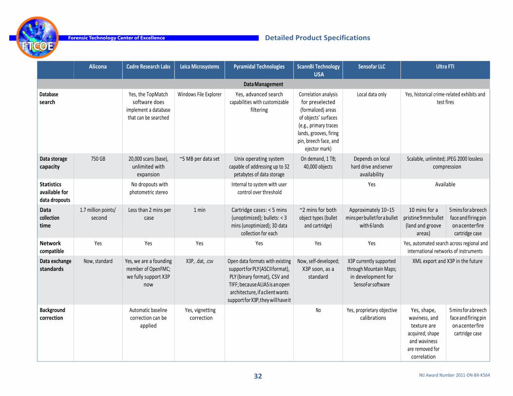
32 NIJ Award Number 2011-DN-BX-K564
Detailed Product Specifications
Alicona Cadre Research Labs Leica Microsystems Pyramidal Technologies ScannBi Technology USA
Sensofar LLC Ultra FTI
Data Management
Database search
Yes, the TopMatch software does
implement a database that can be searched
Windows File Explorer Yes, advanced search capabilities with customizable
filtering
Correlation analysis for preselected (formalized) areas
of objects’ surfaces (e.g., primary traces lands, grooves, firing pin, breech face, and
ejector mark)
Local data only Yes, historical crime-related exhibits and test fires
Data storage capacity
750 GB 20,000 scans (base), unlimited with
expansion
~5 MB per data set Unix operating system capable of addressing up to 32
petabytes of data storage
On demand, 1 TB; 40,000 objects
Depends on local hard drive and server
availability
Scalable, unlimited; JPEG 2000 lossless compression
Statistics available for data dropouts
No dropouts with photometric stereo
Internal to system with user control over threshold
Yes Available
Data collection time
1.7 million points/ second
Less than 2 mins per case
1 min Cartridge cases: < 5 mins (unoptimized); bullets: < 3 mins (unoptimized); 3D data
collection for each
~2 mins for both object types (bullet
and cartridge)
Approximately 10–15 mins per bullet for a bullet
with 6 lands
10 mins for a pristine 9 mm bullet
(land and groove areas)
5 mins for a breech face and firing pin on a center fire cartridge case
Network compatible
Yes Yes Yes Yes Yes Yes Yes, automated search across regional and international networks of instruments
Data exchange standards
Now, standard Yes, we are a founding member of OpenFMC; we fully support X3P
now
X3P, .dat, .csv Open data formats with existing support for PLY (ASCII format), PLY (binary format), CSV and TIFF; because ALIAS is an open architecture, if a client wants
support for X3P, they will have it
Now, self-developed; X3P soon, as a
standard
X3P currently supported through Mountain Maps;
in development for SensoFar software
XML export and X3P in the future
Background correction
Automatic baseline correction can be
applied
Yes, vignetting correction
No Yes, proprietary objective calibrations
Yes, shape, waviness, and texture are
acquired; shape and waviness
are removed for correlation
5 mins for a breech face and firing pin on a center fire cartridge case

33 NIJ Award Number 2011-DN-BX-K564
Detailed Product Specifications
Alicona Cadre Research Labs Leica Microsystems Pyramidal Technologies ScannBi Technology USA
Sensofar LLC Ultra FTI
Measurements and standards
Calibration Traceable to PTB by using an Alicona calibration tool
Calibration uses a known ball grid array
(calibration takes just a few minutes); sinusoidal reference
standards are used for determining lateral and depth resolution; yes, system can scan the NIST standard casing
Calibrated with NIST- traceable etched step
height standard
3D precision reference specimens according to ISO 5436-1 and ISO 25178;
calibration certificates available by UKAS-accredited calibration
laboratory
Routine calibration against 1 mm etalon standard; accuracy check based on
reference standard cylinder, diameter
8 mm
Objectives are calibrated for field flatness and aberration using optical
flat; systems are typically verified for z accuracy
with NIST-traceable step height standards
Calibration done by the supplier
of the 3D sensor: NanoFocus
Self-calibration every 50
acquisitions with the use of a special target inside the acquisition unit
Spatial resolution
Limited by illumination type ~400 microns (SL
640 microns)
Typical lateral resolution: 1.4 microns per pixel (system can
scan up to 0.9 microns per pixel)
140 microns 2 x 2 microns Theoretically ~1 microns
Dependent on technology and objective; highest
resolution is 150 microns lateral (half pitch)
3 pixels wide: ~10 microns
3 pixels wide: ~15 microns for breech face images and ~10 microns for
firing pin, ejector mark, and rim fire
images
Best vertical resolution
10 microns (SL 20 microns)
Typical depth resolution of 1 micron
(assessed using reference standard)
0.1 micron [as reported, may not be specific to firearm
toolmarks]
100 microns Theoretically ~1 micron
Dependent on technology and objective; interferometry resolution
is better than 1 micron
0.2 micron Approximately 1 micron
Smallest vertical slice interval
68 microns ~ 0.1 micron (least significant digit)
Dependent on technology and objective; PSI vertical slice with optional Piezo stage is about 1 microns
Fixed value of 2 microns
Lateral range N/A Full-size cartridge case or bullet Images can be stitched to cover large areas;
depending on stage size, up to 300 x 300 microns
Object limited only Wavelength of approximately
10 microns (i.e., 2 times the FOV for breech face
images)

34 NIJ Award Number 2011-DN-BX-K564
Detailed Product Specifications
Alicona Cadre Research Labs Leica Microsystems Pyramidal Technologies ScannBi Technology USA
Sensofar LLC Ultra FTI
Measurements and standards
Vertical measurement range for a single image
Up to 23 microns (SL Up to 26 microns)
N/A Working; distance- dependent
4 microns Several microns Dependent on technology and objective; ranges from 300 microns for high NA objectives to 17 microns
for low NA objectives
2 microns ~250 microns; limited by the
microscope depth of field
In-process surface follower technology
Yes N/A N/A Height and tilt are automatically detected,
and measurement range is automatically adjusted
Yes Yes, automatic surface following for pristine and
deformed bullets as well as fragments
(including "V" shaped)
N/A
Varied surfaces
Yes Works with any surface, including glass or mirror; it is also possible to
scan live tissue (e.g., fingerprints)
Thick/Thin film measurement
White light interfero-metry is robust against surface
properties; it measures transparent, metallic, diffusive, and highly reflective surfaces
Metal surfaces of bullets and
cartridges, and plastic surfaces (castings)
Yes, from mirror surface to very rough
Yes
Dynamic range of camera
N/A N/A > 48 dB 8 bits 12 bits
Working distance
Objective-lens- dependent
N/A 13 (5x)–0.2 mm (150x)
3.8 mm 41 mm Dependent on technology and objective; ranges from 300 microns for high NA objectives to 17 mm for low NA objectives; super
long working distance objectives are available
with working distance up to 37 mm
1 cm 9 cm

35 NIJ Award Number 2011-DN-BX-K564
Detailed Product Specifications
Alicona Cadre Research Labs Leica Microsystems Pyramidal Technologies ScannBi Technology USA
Sensofar LLC Ultra FTI
Measurements and standards
Measurable range of caliber
All 22 short to 7.62 x 39 mm (additional
calibers can be accommodated with
adapters)
40 mm Up to 20 mm Virtually unlimited Calibers from 0.17–0.700, and an effective diameter
from 4–20 mm
Calibers from 0.17–0.50 and
from .410 bore to 8-gauge for shot shells, and an
effective diameter from 2–27 mm
Motorized scanning (x,y,z)
Yes, motorized rotation and tilt optional (SL Yes,
motorized rotation optional)
N/A Yes (x,y,z) Yes Yes Yes (x,y,z) Yes, automated acquisition: x, y, z (focus), tilt,
rotation, lighting
Yes, automated acquisition, y, z (focus), zoom, rotation, lighting
Reliability of measure- ments (based on mechanical stage movement)
N/A Reproducibility, repeatability, precision assessed by recently
completed study; publication to be submitted in 2016
< 1 micron XYZ stages have optical encoders with 100 nm
resolution
The system x-y scanning stage is fully self-designed; theoretically ~ 1
micron
X-Y scanning reproducibility is in the range of (x,y) scanning
Measurements are not
dependent on the mechanical stages
reproducibility
N/A, all ROIs are captured on a single camera's
FOV
Number of camera pixels
1,840 x 1,840 (SL 2,000 x 2,000)
Current: 18 million; next version likely 50
million
1,360 x 1,024 Typical measurement of cartridge case comprises 25
megapixels (stitched)
At the moment, 510 x 492; soon 2,048 x
1,536
1,360 x 1,024 512 x 512 total pixels contained in the outputted bullet image is extended
with image stitching
960 x 960
Maximum slope
87° Theoretical: Up to 90° 85° (with 0.95 NA objective)
80° for technical surfaces with residual roughness
Up to ~ 90⁰ (reported theoretical)
71° for confocal with 0.95 NA objective, slopes up to 86° can be measured with focus variation and with
rough surfaces
17° > 30°

36 NIJ Award Number 2011-DN-BX-K564
Detailed Product Specifications
Alicona Cadre Research Labs Leica Microsystems Pyramidal Technologies ScannBi Technology USA
Sensofar LLC Ultra FTI
Measurements and standards
Field of view with 20x objective
0.81 x .81 mm (SL 1 x 1 mm)
N/A, using our 3x objective single image field of view is ~35
mm2
877 x 660 microns 580 x 556 microns N/A, the system objective 2x, field of view 2.1x 1.7 mm
877 x 660 microns 1.6 mm x limited by stitching (10x objective); a full circumference of the bullet can be
done
3.2 x 3.2 mm (firing pin, ejector,
and rim fire) with 1.5x zoom objective and 4.8 x 4.8 mm for breech
face with 1.0x zoom objective
Measurement point density
Depending on objective, best : 0.09 micron (SL Depending on
objective, best: 0.2 micron)
Typical: 1.4 micron/ pixel; maximum 0.9
micron/pixel
N/A 2 x 2 micron 280 points/mm Depends on technology and objective
N/A
Conformance with standards for roughness measurement
Yes System will comply with NIST OSAC standards once
published; these standards are still
being created and will build from the cited ISO and ASME documents
ISO 4287, ISO 13565, ISO 12085, ISO 12780,
ISO 12181, ASME B46.1, MBN 31 007-
12, VDA 2007
Yes Yes N/A
Conformance with standards for surface measurement
Yes System will comply with NIST OSAC standards once
published; these standards are still
being created and will build from the cited ISO and ASME documents
ISO 4287, ISO 13565, ISO 12085, ISO 12780,
ISO 12181, ASME B46.1, MBN 31 007-
12, VDA 2007
Yes Yes N/A
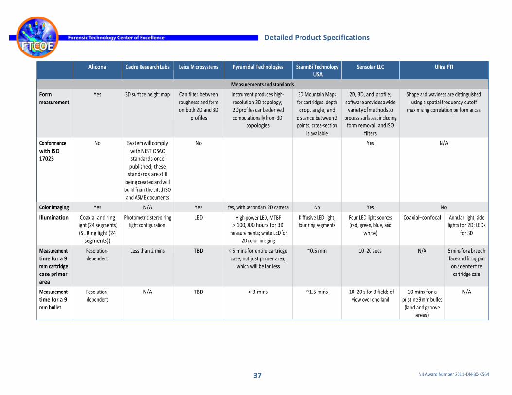
37 NIJ Award Number 2011-DN-BX-K564
Detailed Product Specifications
Alicona Cadre Research Labs Leica Microsystems Pyramidal Technologies ScannBi Technology USA
Sensofar LLC Ultra FTI
Measurements and standards
Form measurement
Yes 3D surface height map Can filter between roughness and form on both 2D and 3D
profiles
Instrument produces high- resolution 3D topology; 2D profiles can be derived computationally from 3D
topologies
3D Mountain Maps for cartridges: depth drop, angle, and
distance between 2 points; cross-section
is available
2D, 3D, and profile; software provides a wide
variety of methods to process surfaces, including
form removal, and ISO filters
Shape and waviness are distinguished using a spatial frequency cutoff
maximizing correlation performances
Conformance with ISO 17025
No System will comply with NIST OSAC standards once
published; these standards are still
being created and will build from the cited ISO and ASME documents
No Yes N/A
Color imaging Yes N/A Yes Yes, with secondary 2D camera No Yes No
Illumination Coaxial and ring light (24 segments) (SL Ring light (24
segments))
Photometric stereo ring light configuration
LED High-power LED, MTBF > 100,000 hours for 3D
measurements; white LED for 2D color imaging
Diffusive LED light, four ring segments
Four LED light sources (red, green, blue, and
white)
Coaxial–confocal Annular light, side lights for 2D; LEDs
for 3D
Measurement time for a 9 mm cartridge case primer area
Resolution- dependent
Less than 2 mins TBD < 5 mins for entire cartridge case, not just primer area,
which will be far less
~0.5 min 10–20 secs N/A 5 mins for a breech face and firing pin on a center fire cartridge case
Measurement time for a 9 mm bullet
Resolution- dependent
N/A TBD < 3 mins ~1.5 mins 10–20 s for 3 fields of view over one land
10 mins for a pristine 9 mm bullet
(land and groove areas)
N/A

38 NIJ Award Number 2011-DN-BX-K564
Detailed Product Specifications
Alicona Cadre Research Labs Leica Microsystems Pyramidal Technologies ScannBi Technology USA
Sensofar LLC Ultra FTI
Measurements and standards
Security System will comply with NIST OSAC standards once
published; these standards are still
being created and will build from the cited ISO and ASME documents
No Not at present Yes, ISO 27001 and NIST SP 800-53
Training, Costs, and Current Users
Is training offered?
Yes Yes, firearms examiners and technicians have
been successfully trained
Yes, Leica-certified trainer
Yes, have trained operators with no background, beginner,
intermediary, and advanced
Yes. computer experience and ballistics grounds
Yes, minimal background required
Yes, no specific background required
Technical support provided?
Yes, all methods and different service contracts available
Yes, phone, e-mail, and Web
Installation and training provided
with purchase; online, telephone, and
Internet training and support available per
request
Yes, five support plans (bronze, silver, gold, and platinum) up to 24/7/365 support options with phone, e-mail, and Web contact to fit any client mission criticality requirements; 2-year
default warranty
Yes, full range support Yes, typical installation includes two days on site, with follow-on training
available
1-year warranty and complete safeguard coverage for state and locals; NIBIN customer support and program
management
Estimated cost < $100,000
(SL) x x
$100,000– $500,000
x x x x x x
> $500,000 x x
Other Suite of products for forensic ballistics and firearms
registration
Depends on configuration
Free as part of the ATF NIBIN program
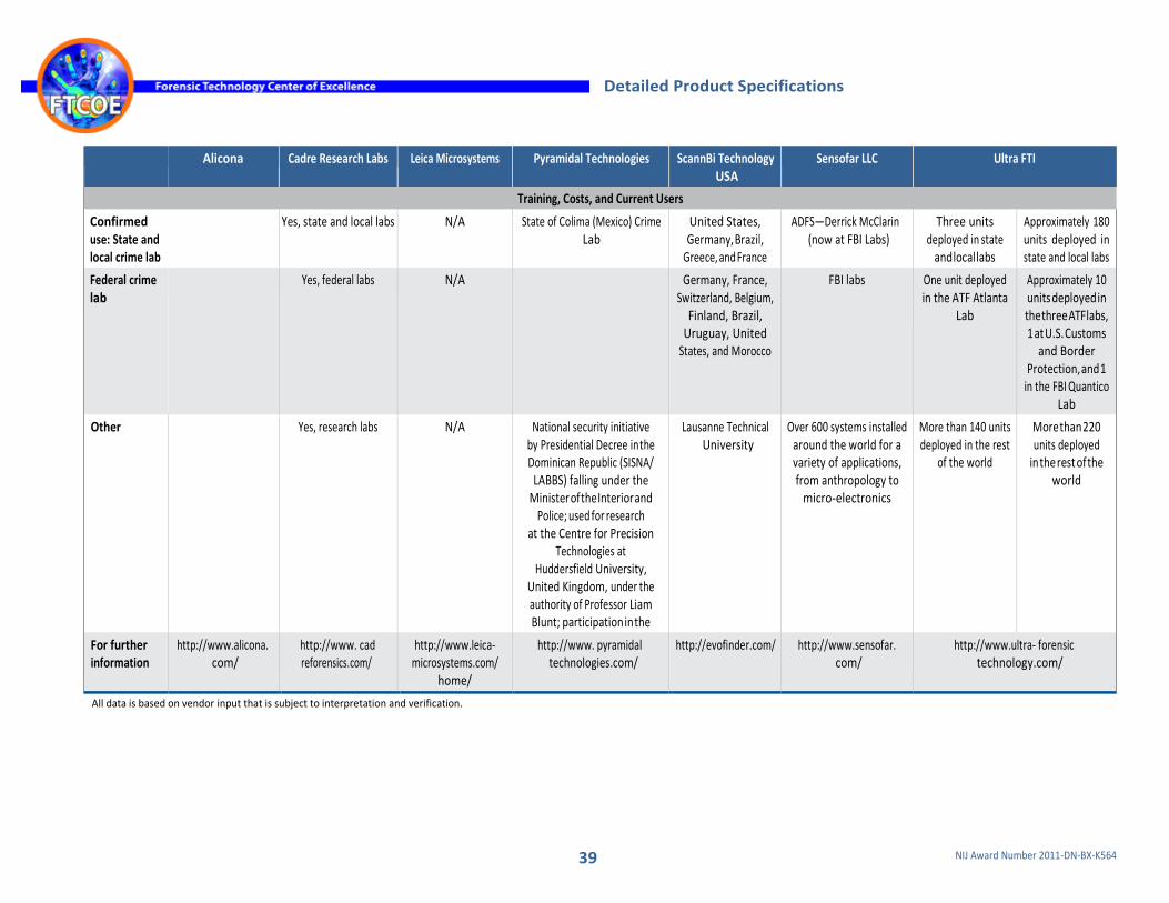
39 NIJ Award Number 2011-DN-BX-K564
Detailed Product Specifications
Alicona Cadre Research Labs Leica Microsystems Pyramidal Technologies ScannBi Technology USA
Sensofar LLC Ultra FTI
Training, Costs, and Current Users
Confirmed use: State and local crime lab
Yes, state and local labs N/A State of Colima (Mexico) Crime Lab
United States, Germany, Brazil,
Greece, and France
ADFS—Derrick McClarin (now at FBI Labs)
Three units deployed in state
and local labs
Approximately 180 units deployed in state and local labs
Federal crime lab
Yes, federal labs N/A Germany, France, Switzerland, Belgium,
Finland, Brazil, Uruguay, United
States, and Morocco
FBI labs One unit deployed in the ATF Atlanta
Lab
Approximately 10 units deployed in the three ATF labs, 1 at U.S. Customs
and Border Protection, and 1
in the FBI Quantico Lab
Other Yes, research labs N/A National security initiative by Presidential Decree in the Dominican Republic (SISNA/
LABBS) falling under the Minister of the Interior and
Police; used for research at the Centre for Precision
Technologies at Huddersfield University,
United Kingdom, under the authority of Professor Liam Blunt; participation in the
EU Odyssey Project
Lausanne Technical University
Over 600 systems installed around the world for a variety of applications, from anthropology to
micro-electronics
More than 140 units deployed in the rest
of the world
More than 220 units deployed
in the rest of the world
For further information
http://www.alicona. com/
http://www. cad reforensics.com/
http://www.leica- microsystems.com/
home/
http://www. pyramidal technologies.com/
http://evofinder.com/ http://www.sensofar. com/
http://www.ultra- forensic technology.com/
All data is based on vendor input that is subject to interpretation and verification.