fore-sight mc-2000 series cerebral oximeter fore-sight small sensors the fore-sight mc-2000 series...
TRANSCRIPT

21-02-0250 Rev 00 09/09
FORE-SIGHT® MC-2000 Series Cerebral Oximeter
Field Service Manual

FORE-SIGHT Field Service Manual
Page 2 21-02-0250 Rev 00 09/09
Page intentionally left blank

FORE-SIGHT Field Service Manual
21-02-0250 Rev 00 09/09 Page 3
FORE-SIGHT MC-2000 Series Monitor
MODEL DESCRIPTION MC-2000 Dual Channel Cerebral Oximeter, small battery (for use with Medium and Large sensors) MC-2010 Dual Channel Cerebral Oximeter with battery backup (for use with Medium and Large sensors) MC-2020 Dual Channel Universal Cerebral Oximeter, small battery (for use with all sensors) MC-2030 Dual Channel Universal Cerebral Oximeter with battery backup (for use with all sensors)
IMPORTANT:
This manual addresses all parameters of the FORE-SIGHT MC-2000 Series Monitor. You may have purchased a model that does not have all the parameters referred to in this manual. This Manual remains suitable for use.
Read this Manual completely before using this equipment.
WARNING:
The FORE-SIGHT MC-2000 Series Monitor is to be operated by qualified personnel only. Before use, carefully read this manual, including accessory directions for use, all precautionary information, and specifications. The user must check that the equipment functions safely and in proper working condition before use.
First Printing: 09/2009

FORE-SIGHT Field Service Manual
Page 4 21-02-0250 Rev 00 09/09
HOW TO CONTACT US
CAS Medical Systems, Inc Authorized Representative in
44 East Industrial Road European Union Branford, CT 06405
U.S.A. EC REP
Phone: MediMark® Europe. (800) 227-4414 11 rue E. Zola 38100 (203) 488-6056 Grenoble. France
Fax:
(203) 488-9438
E-Mail: [email protected] [email protected]
Web: www.casmed.com
Please contact the distributor in the country of purchase if product information or service should be required.
Copyright 2007 - 2009 CAS Medical Systems, Inc. All rights reserved. No part of this manual may be reproduced without the written permission of CAS Medical Systems, Inc. CAS reserves the right to make changes to this manual and improvements to the product it describes at any time without notice or obligation.

FORE-SIGHT Field Service Manual
21-02-0250 Rev 00 09/09 Page 5
Table of Contents
1 INTRODUCTION AND INTENDED USE 9 INTRODUCTION 9 INDICATIONS FOR USE 9 CONTRAINDICATIONS 9 BRIEF DEVICE DESCRIPTION 9 PATIENT ENVIRONMENT 10 MANUAL OVERVIEW 10 CONVENTIONS 10 RELATED DOCUMENTS 10
2 SERVICE POLICY 11 WARRANTY POLICY 11 EXTENDED CARE SERVICE PROGRAMS 12 RETURNING THE MONITOR FOR REPAIR 12 WEEE SELECTIVE TREATMENT AND RECYCLING INFORMATION 12
3 SAFETY MEASURES AND WARNINGS 13 AUTOMATIC SAFETY FEATURES 17 MANUFACTURERS DECLARATION OF CONFORMITY 18
4 SYMBOLS 21 SYMBOLS ON MONITOR 21 SYMBOLS NEAR ACCESSORY CONNECTIONS 21 SYMBOLS APPEAR ON PACKAGING IN PLACE OF TEXT 21
5 MONITOR CONTROLS 23 FRONT PANEL 23 FRONT PANEL CONTROLS / SYMBOLS 23
On / Standby Key 23 Alarm Silence / Reset Key 24 Average / Auto / Left / Right Key 24 Sensor Start / Restart Key 24 Rotary Control Knob 25 Symbols 25
REAR PANEL 26

FORE-SIGHT Field Service Manual
Page 6 21-02-0250 Rev 00 09/09
6 EXTERNAL DEVICE INTERFACING 27 OVERVIEW 27 SELECTING THE SERIAL PORTS 28 CONNECTING TO PHILIPS INTELLIVUE 30 FORE-SIGHT SERIAL PORT DATA OUTPUT 31
Simple Comma Text 31 Test Port 32 Printer 32
USB 33
7 ROUTINE MAINTENANCE 35 CLEANING 35
Cleaning Overview 35 THE MONITOR 35 THE DISPLAY 35 CLEAN MONITOR CABLES 36 CLEANING PATIENT CABLES 36 FIBER OPTIC CONNECTORS 36 SAFETY CHECKS 36 SYSTEM CHECKS 37 PREVENTATIVE MAINTENANCE 37 BATTERY 37
8 TROUBLESHOOTING 39 HOW DOES THE FORE-SIGHT CEREBRAL OXIMETER WORK? 39 LOCATION of LASER LABELS 40 SYSTEM TROUBLESHOOTING 41
SctO2 USER MESSAGES 45 Error Messages in the Message Window 46
9 MAINTENANCE PROCEDURES 49 INTRODUCTION 49
Equipment Required 49 Data Sheet 49 Battery Charge 49 Turning the FORE-SIGHT MC-2000 Series Monitor “On” 50 Displaying the Date and Time 50 Alarm Audio 50

FORE-SIGHT Field Service Manual
21-02-0250 Rev 00 09/09 Page 7
OXIMETRY SIMULATION CHECK 51
SctO2 Simulator Check 51 ELECTRICAL SAFETY CHECKS 51
Leakage 51 DATA SHEET 53
10 SERVICE PROCEDURES 55 INTRODUCTION 55
Tools Required 55 AC FUSE 55 BATTERY FUSE 56
Disconnecting the Battery 57 Replacing the Battery Fuse 58
CALLING CASMED for an RMA NUMBER 59 CUSTOMER CARE PLAN 61
11 SPARE PARTS 63
12 SPECIFICATIONS 65 SctO2 MEASUREMENT 65 LASER INFORMATION 65 PATIENT ALARMS 65 DISPLAY 66 PHYSICAL DIMENSIONS AND WEIGHT 66 OPERATING ENVIRONMENT 66 STORAGE/TRANSPORT ENVIRONMENT 66 POWER 66 SERIAL INTERFACE 67 STANDARDS 67
FORE-SIGHT Field Service Manual
Page 8 21-02-0250 Rev 00 09/09
Figures Figure 1: Patient Environment 10 Figure 2: Front Panel View 23 Figure 3: Clockwise and Counterclockwise Directions 25 Figure 4: Rear Panel View 26 Figure 5: RS232 Connector Pin Layout 27 Figure 6: Ports 29 Figure 7: Port Setup 29 Figure 8: Ports 32 Figure 9: USB Connector Pin Layout 33 Figure 10: Location of Internal Laser Labels 40 Figure 11: FORE-SIGHT MC-2000 Series Monitor Overall Block Diagram 41 Figure 12: No Monitor Power 42 Figure 13: Power up Response 43 Figure 14: SctO2 Trouble Shooting 44 Figure 15: AC Fuse Placement 56 Figure 16: Battery Fuse Placement 58
Tables
Table 1: DB9 Male Pin Out 27 Table 2: DB9 Female Pin Out 27 Table 3: User Messages 47 Table 4: System Error Definition 48

FORE-SIGHT Field Service Manual
21-02-0250 Rev 00 09/09 Page 9
1 INTRODUCTION AND INTENDED USE
INTRODUCTION The FORE-SIGHT MC-2000 Series Monitor is a pre-configured monitor that can include the following measurement functions:
• Absolute cerebral tissue oxygen saturation (SctO2)
The FORE-SIGHT MC-2000 Series Monitor detects oxygenation changes in biological tissue mainly at the microcirculation level (capillary, arteriole, and venule) based on different absorption characteristics of the chromophores oxyhemoglobin (HbO2) and deoxyhemoglobin (Hb) in the near-infrared spectrum. A biological spectroscopic window exists at the wavelength range 660–940 nm in which Hb and HbO2 can be differentiated and measured. Brain tissue oxygen saturation (SctO2) is determined from the ratio ((HbO2) ⁄ (HbO2 + Hb)) × 100%, which assumes a mixture of venous to arterial to venous blood of 70/30, respectively.
INDICATIONS FOR USE The FORE-SIGHT® Cerebral Oximeter, Model MC-2000 Series is indicated for the continuous noninvasive monitoring of regional hemoglobin oxygen saturation of blood in the brain (SctO2). It is intended for use in any individual at risk for reduced-flow or no-flow ischemic states.
When used with FORE-SIGHT large sensors, the FORE-SIGHT MC-2000 Cerebral Oximeter Monitor is indicated for use with adults and children over 40Kg. When used with the FORE-SIGHT medium sensors, the FORE-SIGHT MC-2000 Cerebral Oximeter is indicated for use with small adults and children between 4 kg and 80 kg. When used with FORE-SIGHT small sensors the FORE-SIGHT MC-2000 Series Cerebral Oximeter Monitor is indicated for infants and neonates ≤ 8Kg.
CONTRAINDICATIONS • The FORE-SIGHT MC-2000 Series Monitor sensor is contraindicated for use on
patients with limited skin access or allergic reaction to electrode adhesive.
• Disposable SctO2 sensors are contraindicated for use for prolonged periods. The sensor site must be checked at least every eight hours; and if the circulatory condition or skin integrity has deteriorated, the sensor should be applied to a different site.
• Do not adhere sensors to underdeveloped, immature, compromised, or healing skin.
• No other contraindications are known at this time.
BRIEF DEVICE DESCRIPTION The FORE-SIGHT MC-2000 Series Monitor utilizes a 6.4” TFT, color, VGA LCD Display integrated into a front bezel with dedicated keys and a rotary-encode control knob. The FORE-SIGHT MC-2000 Series Monitor is constructed using a full metal rear enclosure. Batteries, Power Supply and 2 NIRS Signal Acquisition Module (NSAM) mounted within the enclosure behind the front bezel. Each NSAM shall incorporate a proprietary algorithm and a Patient Cable that is placed on the forehead. The front panel allows connection to a USB flash memory stick. The rear panel allows connection to other devices including, but not limited to: an external printer, a multi-parameter vital signs monitor and IBM compatible or MAC PC for diagnostics and program downloading.

FORE-SIGHT Field Service Manual
Page 10 21-02-0250 Rev 00 09/09
The FORE-SIGHT MC-2000 Series Monitor shall be capable of operating on AC or internal batteries. When on AC the batteries shall be charging.
PATIENT ENVIRONMENT The FORE-SIGHT MC-2000 Series Monitor has been tested with specific parts of the “system” used within the Patient Environment. Figure 1, defines the Patient Environment.
Figure 1: Patient Environment
MANUAL OVERVIEW This manual contains block diagram information about the CAS FORE-SIGHT MC-2000 Series Monitor. Only qualified service personnel should service this product.
It is the user’s responsibility to ensure that the product is properly maintained and that the monitor is in safe and proper operating condition before being put into use.
Before servicing the CAS FORE-SIGHT MC-2000 Series Monitor, read the User’s Manual carefully.
CAS Medical Systems, Inc. believes the information herein is complete and accurate, but accepts no liability for errors, omissions, or misrepresentations.
CONVENTIONS In this manual, “WARNING”, “CAUTION”, and “NOTE” mean the following:
WARNING: Directions that warn of conditions that put the patient or the caregiver at risk.
CAUTION:
Directions that help to avoid damaging the monitor or losing data.
NOTE: Directions that make it easier to use the monitor, something not readily apparent.
RELATED DOCUMENTS To perform test and troubleshooting procedures, you must know how to operate the monitor. Refer to the CAS FORE-SIGHT MC-2000 Series Monitor User’s Manual.

FORE-SIGHT Field Service Manual
21-02-0250 Rev 00 09/09 Page 11
2 SERVICE POLICY
WARRANTY POLICY All products are sold by CAS Medical Systems, Inc. (CASMED®), under the warranties set forth in the following paragraphs. Such warranties are extended only with respect to the purchase of this product directly from CAS Medical Systems, Inc., or CASMED’s Authorized Distributors as new merchandise and are extended to the first buyer thereof, other than for resale.
The CASMED FORE-SIGHT® Cerebral Oximeter monitor is warranted for a period of twelve (12) months. All products, if applicable, are warranted to be free from functional defects in materials and workmanship and to conform to the description of the product contained in the User Guide, published specifications, and accompanying labels and/or inserts, provided that the same is properly operated under conditions of normal use in accordance with applicable safety and regulatory requirements, and that replacements and repairs are made in accordance with the instructions provided by CAS Medical Systems, Inc.
The same warranty conditions are made for a period of twelve (12) months with respect to the battery. A ninety (90) days warranty is provided for non-disposable accessories such as reusable monitor cables and other accessories provided by CASMED as part of the original purchase. CASMED warrants disposable or single-patient-use products, including SctO2 sensors for out-of-box failure only. Where the accessory is not a CAS Medical Systems, Inc., manufactured product, the manufacturer’s own warranty applies. Warranty of accessories purchased separately from listed suppliers will be the responsibility of such listed suppliers. Damage to any part through misuse, neglect, or accident, or by affixing any accessories or attachments other than CASMED manufactured accessories or attachments, is not covered by this warranty.
The foregoing warranties shall not apply if the product has been configured, modified, adjusted or repaired other than by CAS Medical Systems, Inc., or by persons expressly authorized by CAS Medical Systems, Inc., or not in accordance with written instructions provided by CAS Medical Systems, Inc., or if the product has been subjected to misuse, negligence, or accident.
CASMED reserves the right to perform warranty service operations in its own factory, at an authorized repair facility, or at the customers’ site. The sole and exclusive obligation of CAS Medical Systems, Inc., and Buyer’s sole and exclusive remedy under the above warranties, is limited to repairing or replacing, free of charge, a product which is reported in writing or via telephone to CAS Medical Systems, Inc., has a Return Merchandise Authorization (RMA) number assigned and which is returned during normal business hours, transporting charges prepaid to:
CAS Medical Systems, Inc. 44 East Industrial Road Branford, CT 06405 USA
Telephone: +1 203 488 6056 Fax: +1 203 488 9438
E-mail: [email protected]

FORE-SIGHT Field Service Manual
Page 12 21-02-0250 Rev 00 09/09
CAS MEDICAL SYSTEMS, INC. SHALL NOT BE OTHERWISE LIABLE FOR ANY DAMAGES INCLUDING, BUT NOT LIMITED TO, INCIDENTAL DAMAGES, CONSEQUENTIAL DAMAGES OR SPECIAL DAMAGES.
THERE ARE NO EXPRESS OR IMPLIED WARRANTIES WHICH EXTEND BEYOND THE WARRANTIES HEREINABOVE SET FORTH. CAS MEDICAL SYSTEMS, INC. MAKES NO WARRANTY OF MERCHANTABILITY OR FITNESS FOR A PARTICULAR PURPOSE WITH RESPECT TO THE PRODUCT OR PARTS THEREOF.
EXTENDED CARE SERVICE PROGRAMS CAS Medical Systems offers an Extended Care Service Contract program for the CAS FORE-SIGHT MC-2000 Series Monitor.
Contact CAS Medical Systems’ Customer Service Department for more information.
RETURNING THE MONITOR FOR REPAIR Before returning a product for repair you must obtain authorization from CAS Medical Systems. An RMA (Return Merchandise Authorization) number will be issued to you by our Service Department. Be sure to note this number on the outside of your shipping box. Returns without an RMA number will not be accepted for delivery.
NOTE:
Save the original shipping container and it’s inside packing material should the monitor need to be returned for service.
Refer to Page 4, How To Contact Us for important telephone numbers, fax numbers and email addresses.
WEEE SELECTIVE TREATMENT AND RECYCLING INFORMATION To facilitate the sound treatment of WEEE, information will be made available for current CASMED products upon request. EU distributors and treatment facility personnel may contact [email protected] to obtain relevant information.

FORE-SIGHT Field Service Manual
21-02-0250 Rev 00 09/09 Page 13
3 SAFETY MEASURES AND WARNINGS WARNING:
The FORE-SIGHT MC-2000 Series Monitor is defibrillator-proof. It may remain attached to the patient during defibrillation, but the readings may be inaccurate during use and less than twenty (20) seconds thereafter.
The FORE-SIGHT MC-2000 Series Monitor is intended only as an adjunct in patient assessment. It must be used in conjunction with clinical signs and symptoms.
DO NOT rely exclusively on the audible alarm system for patient monitoring. Adjustment of alarm volume to a low level during patient monitoring may result in a hazard to the patient. Remember that the most reliable method of patient monitoring combines patient assessment and close personal surveillance with correct operation of monitoring equipment.
DO NOT place the FORE-SIGHT MC-2000 Series Monitor face against a surface. This will cause the alarm to be muffled.
DO NOT place the FORE-SIGHT MC-2000 Series Monitor back against a surface. This will block the fan and cause the unit to overheat, shutting it off.
DO NOT place the FORE-SIGHT MC-2000 Series Monitor or accessories in any position that might cause it to fall.
DO NOT lift or pull the FORE-SIGHT MC-2000 Series Monitor by any cable.
DO NOT place the FORE-SIGHT MC-2000 Series Monitor where the controls can be changed by the patient.
DO NOT use the FORE-SIGHT MC-2000 Series Monitor for any purpose other than specified in this manual. Doing so will invalidate the monitor’s warranty.
DO NOT connect more than one patient to a monitor.
Leakage Current Test – The interconnection of auxiliary equipment, including a patient monitor or other patient-connected equipment, with this device may increase the total leakage current. When interfacing with other equipment, qualified biomedical engineering personnel must perform a test for leakage current before using it with patients. Serious injury or death could result if the leakage current exceeds applicable standards.
The FORE-SIGHT MC-2000 Series Monitor is to be operated by qualified personnel only. This manual, accessory direction for use, all precautionary information, and specifications should be read before use.
DO NOT expose the FORE-SIGHT MC-2000 Series Monitor to excessive moisture such as direct exposure to rain. Excessive moisture can cause the FORE-SIGHT MC-2000 Series Monitor to perform inaccurately or fail.
Explosion Hazard – DO NOT use the monitor in the presence of a flammable anesthetic mixture with air or with oxygen or nitrous oxide.

FORE-SIGHT Field Service Manual
Page 14 21-02-0250 Rev 00 09/09
WARNING
DO NOT place containers containing liquids on or near the FORE-SIGHT MC-2000 Series Monitor. Liquids spilled on the monitor may cause it to perform inaccurately or fail.
Patient Safety – If the monitor, cables, power cord or sensor are damaged in any way, discontinue use immediately.
The FORE-SIGHT MC-2000 Series Monitor is not “Category AP or APG Equipment.”
Electromagnetic Compatibility (EMC) – The equipment needs special precautions if it is placed close to a strong transmitter such as X-ray equipment, MRI devices, TV, AM/FM radios, police/fire stations, an amateur (“ham”) radio operator, an airport, or a cellular phone. Their signals could interfere with the monitor, which may result in disruption of performance of this device or prevent the clear reception of signals by the monitor. This equipment has been tested and found to comply with the limits for medical devices to the EN 60601-1-2: 2002, Medical Device Directive 93/42/EEC. These limits are designed to provide reasonable protection against harmful interference in a typical medical installation. This equipment generates, uses, and can radiate radio frequency energy and, if not installed and used in accordance with the instructions, may cause harmful interference to other devices in the vicinity. However, there is no guarantee that interference will not occur in a particular installation. If this equipment does cause harmful interference to other devices, which can be determined by turning the equipment off and on, the user is encouraged to try to correct the interference by one or more of the following measures:
• Reorient or relocate the receiving device. • Increase the separation between the devices.
Consult the manufacturer for help.
Severe anemia and edema may cause erroneous or no SctO2 readings.
If the integrity of the protective earth conductor is in doubt, the unit may be operated from the internal batteries by disconnecting the AC line cord completely from the unit.
To ensure patient safety and preserve device performance, DO NOT place the monitor in any position that might cause it to fall.
DO NOT lift or pull the monitor by any sensor cable or line as they could disconnect from the monitor, causing the monitor to fall on the patient.
To avoid electric shock or device malfunction, liquids must not be allowed to enter the device. If liquids have entered a device, take it out of service and have it checked by a service technician before it is used again.
The FORE-SIGHT MC-2000 Series Monitor provides “DRIP-PROOF” level of protection from ingress to moisture.
DO NOT place liquids on top of the monitor.
DO NOT immerse the monitor or power cord in water or any liquid.
DO NOT gas sterilize or autoclave the monitor.

FORE-SIGHT Field Service Manual
21-02-0250 Rev 00 09/09 Page 15
WARNING
DO NOT touch any part of non-medical electrical equipment and the patient at the same time after removal of covers, connectors, etc.
Where the integrity of the external protective conductor in the installation or its arrangement is in doubt, EQUIPMENT shall be operated from its INTERNAL ELECTRICAL POWER SOURCE.
Isolation of product from mains can only be achieved by removal of external power cord.
Route all cables away from patient’s throat to avoid possible strangulation.
DO NOT, under any circumstances, perform any testing or maintenance on the monitor or power cord while the unit is being used to monitor a patient. Unplug the power cord before cleaning or servicing the monitor. The operator should not perform any servicing except as specifically stated in this manual.
The functions of the alarm system for monitoring of the patient must be verified at regular intervals.
Periodically, and whenever the integrity of the product is in doubt, test all functions.
DO NOT use a frayed or damaged Power Supply cord or any accessory if you notice any sign of damage. Contact CAS Medical Systems, Inc., for assistance.
DO NOT come into contact with patients during defibrillation. Otherwise serious injury or death could result.
Only use CASMED-supplied patient cables with this monitor. The use of unprotected patient cables creates the potential for making an electrical connection to ground or to a high voltage power source which can cause serious injury or death to the patient.
DO NOT modify or alter the SctO2 sensor in any way. Alterations or modification may affect performance and/or accuracy.
The use of accessory equipment not complying with the equivalent safety requirements of this equipment may lead to a reduced level of safety of the resulting system. Consideration relating to the choice shall include:
- Use of the accessory in the patient environment.
- Evidence that the safety certification of the accessory has been performed in accordance to the appropriate IEC 60601-1 and/or IEC 60601-1-1 harmonized national standard.

FORE-SIGHT Field Service Manual
Page 16 21-02-0250 Rev 00 09/09
CAUTION
For continued safe use of this equipment, it is necessary that the listed instructions be followed. However, instructions listed in this manual in no way supersede established medical practices concerning patient care.
The Battery fuse must be installed for the unit to operate with the internal batteries. If the unit is not to be used for periods greater than 1 week, the battery fuse should be removed.
The USB connector only accommodates a USB flash memory stick; DO NOT connect any other USB device or cable to the USB connector
Qualified biomedical engineering personnel only must interface monitoring equipment with other types of medical equipment. Be certain to consult manufacturers’ specifications to maintain safe operation.
Measurements may be affected in the presence of strong electromagnetic sources such as an electrosurgery unit (ESU).
Pressing the front panel keys with a sharp or pointed instrument may permanently damage the switch membrane. Press the keys using only your finger.
If the monitor is accidentally wetted, take it out of operation. It should be thoroughly dried.
Inspect the monitor, cables, power cord and sensors for damage prior to operation. If any damage is noted, the monitor should not be used until it has been serviced. Only personnel authorized to do so by CAS Medical Systems, Inc., should repair the monitor.
If the monitor fails to respond, DO NOT use it until the situation has been corrected by qualified CAS Medical Systems, Inc., personnel.
Grounding reliability can only be achieved when the equipment is connected to an equivalent receptacle marked “Hospital Grade”.
Use only accessories and sensors approved by CAS Medical Systems, Inc., to ensure patient safety and to preserve the integrity, accuracy, and electromagnetic compatibility of the monitor.
Electrosurgery – To prevent unwanted skin burns; apply electrosurgery electrodes as far as possible from all other sensors, a distance of at least 15 cm (6 in.) is recommended.
Federal law restricts this device to sale by or on the order of a physician or properly licensed practitioner.

FORE-SIGHT Field Service Manual
21-02-0250 Rev 00 09/09 Page 17
GENERAL NOTES
The FORE-SIGHT MC-2000 Series Monitor is designed for continuous operation.
The FORE-SIGHT MC-2000 Series Monitor is suitable for use in the presence of electrosurgery; however, measurements may be inaccurate during active use of an ESU.
The monitor is shipped with the appropriate line cord for the country and voltage being used.
The FORE-SIGHT MC-2000 Series Monitor can remain connected to the patient during cardio defibrillation. All other applied parts are “Type BF Defibrillation Proof.”
The monitor has been designed to promote patient safety. All equipment parts are protected against the effects of the discharge of a defibrillator. No separate actions are required when using this equipment with a defibrillator.
There are no known risks with common disposal of equipment or accessories; however, the disposing of accessories should follow in accordance with local hospital policies. The user should ensure these policies do not conflict with any local, state, or federal guidelines.
AUTOMATIC SAFETY FEATURES All equipment parts are protected against the effects of the discharge of a defibrillator. No separate actions are required when using this equipment with a defibrillator.
For FORE-SIGHT Model numbers 2010 and 2030, should the AC line power be interrupted coming into the monitor, the monitor automatically runs off battery power. An indication of this would be the Battery Indicator LED illuminates, three (3) audible beeps are heard and the message “Loss of AC Power” is displayed in the Message Area on the screen.
CAUTION:
Regardless of these safety features, always be sure to check that there are no signs of prolonged impairment of circulation and that the monitor is functioning properly.

FORE-SIGHT Field Service Manual
Page 18 21-02-0250 Rev 00 09/09
MANUFACTURERS DECLARATION OF CONFORMITY
Manufacturers Declaration of Conformity Electronic Emissions and Immunity
The FORE-SIGHT MC-2000 Series Monitor is intended for use in the electromagnetic environment specified below. The customer or the user of the FORE-SIGHT MC-2000 Series Monitor should assure it is used in such an environment.
Emissions Test Compliance Electromagnetic Environment RF emissions – CISPR 11 Group 1 The FORE-SIGHT MC-2000 Series Monitor uses RF energy only for
its internal function. Therefore, its RF emissions are very low and are not likely to cause any interference in nearby electronic equipment.
RF emissions – CISPR 11 Class B Harmonic emissions IEC 61000-3-2 Class A
Voltage fluctuations / flicker emissions
Complies
The FORE-SIGHT MC-2000 Series Monitor is suitable for use in all establishments other than domestic establishments and those directly connected to the public low-voltage Power Supply network that supplies buildings used for domestic purposes.
Immunity Test IEC 60601 Test Level Compliance Level Electromagnetic Environment
Guidance Electrostatic discharge (ESD) IEC 61000-4-2
Level 3
Level 3
The FORE-SIGHT MC-2000 Series Monitor is designed for use in controlled environments only. Per OSHA guidelines for operating rooms, the area must employ adequate static electricity controls. The relative humidity should be maintained at about 50%.
Electrical fast transient/burst IEC 61000-4-4
±2 kV for Power Supply lines ±1 kV for input/output lines
±2 kV for Power Supply lines ±1 kV for input/output lines
The FORE-SIGHT MC-2000 Series Monitor is designed for use in controlled environments only. Per OSHA guidelines for operating rooms, the Mains power quality should be that of a typical commercial or hospital environment.
Surge IEC 61000-4-5
±1 kV line(s) to line(s) mode ±2 kV line(s) to earth mode
±0.5 kV line(s) to line(s) mode ±2 kV line(s) to earth mode
Mains power quality should be that of a typical commercial or hospital environment.
Voltage dips, short interruptions and voltage variations on Power Supply input lines IEC 61000-4-11
< 5% UT (> 95% dip in UT) for 0.5 cycle. 40% UT (60% dip in UT) for 5 cycles. 70% UT (30% dip in UT) for 25 cycles. < 5% UT (> 95% dip in UT) for 5 s
< 5% UT (> 95% dip in UT) for 0.5 cycle. 40% UT (60% dip in UT) for 5 cycles. 70% UT (30% dip in UT) for 25 cycles. < 5% UT (> 95% dip in UT) for 5 s
Mains power quality should be that of a typical commercial or hospital environment. If user of the FORE-SIGHT MC-2000 Series Monitor requires continued operation during power mains interruptions, it is recommended that the FORE-SIGHT MC-2000 Series Monitor be powered from an uninterruptible Power Supply or a battery.
Power frequency (50/60 Hz) magnetic field IEC 61000-4-8
3 A/m 3 A/m Power frequency magnetic fields should be at levels characteristic of a typical location in a typical commercial or hospital environment.
NOTE: UT is the A.C. mains voltage prior to application of the test level.

FORE-SIGHT Field Service Manual
21-02-0250 Rev 00 09/09 Page 19
Guidance and Manufacturer’s Declaration – Electromagnetic Immunity The FORE-SIGHT MC-2000 Series Monitor is intended for use in the electromagnetic environment specified below. The customer or the user of the FORE-SIGHT MC-2000 Series Monitor should insure that it is used in such an environment.
Immunity Test IEC 60601 Test Level Compliance Level
Electromagnetic Environment – Guidance
Conducted RF IEC 61000-4-6 Radiated RF IEC 61000-4-3
3 Vrms 150 kHz to 80 MHz 3 V/m 80 MHz to 2.5 GHz
3 Vrms 3 V/m
Portable and mobile RF communications equipment should be used no closer to any part of the Model MC-2000 Series Monitor, including cables, than the recommended separation distance calculated from the equation applicable to the frequency of the transmitter. Recommended separation distance: d = 1.2√P d = 1.2√P 80 MHz to 800 MHz d = 2.3√P 800 MHz to 2.5 GHz Where P is the maximum output power rating of the transmitter in watts according to the transmitter manufacturer and d is the recommended separation distance in meters. Field strengths from fixed RF transmitters, as determined by an electromagnetic site survey a , should be less than the compliance level in each frequency range. b Interference may occur in the vicinity of equipment marked with the following symbol:
NOTE 1 At 80 MHz and 800MHz, the higher frequency range applies. NOTE 2 These guidelines may not apply in all situations. Electromagnetic propagation is effected by absorption and reflection from structures, objects and people. a Field strengths from fixed transmitters, such as base stations for radio (cellular / cordless) telephones and land mobile radios, amateur radio, AM and FM radio broadcast and TV broadcast cannot be predicted theoretically with accuracy. To assess the electromagnetic environment due to fixed RF transmitters, an electromagnetic site survey should be considered. If the measured field strength in the location in which the Model MC-2000 Series Monitor is used exceeds the applicable RF compliance level above, the 2040 Monitor should be observed to verify normal operation. If abnormal performance is observed, additional measures may be necessary, such as re-orienting or relocating the Model MC-2000 Series Monitor. b Over the frequency range 150 kHz to 80 MHz, field strengths should be less than 3 V/m. Recommended Separation Distances Between Portable and Mobile RF Communications Equipment and the Model 2040
Monitor The Model MC-2000 Series Monitor is intended for use in an electromagnetic environment in which radiated RF disturbances are controlled. The customer or the user of the Model MC-2000 Series Monitor can help prevent electromagnetic interference by maintaining a minimum distance between portable and mobile RF communications equipment (transmitters) and the Model MC-2000 Series Monitor as recommended below, according to the maximum output power of the communications equipment.
Separation distance according to frequency of transmitter (Meters)
Rated maximum output power of transmitter
(Watts)
150 kHz to 80 MHz
d = 1.2√P
80 MHz to 800 MHz
d = 1.2√P
800 MHz to 2.5 GHz
d = 2.3√P
0.01 0.12 0.12 0.23 0.1 0.38 0.38 0.73 1 1.2 1.2 2.3 10 3.8 3.8 7.3 100 12 12 23 For transmitters operating at a maximum output power not listed above, the recommended separation distance d in meters can be estimated using the equation applicable to the frequency of the transmitter, where P is the maximum output power rating of the transmitter in watts according to the transmitter manufacturer. NOTE 1 At 80 MHz and 800 MHz, the separation distance for the higher frequency range applies. NOTE 2 These guidelines may not apply in all situations. Electromagnetic propagation is affected by absorption and reflection from structures, objects, and people.

FORE-SIGHT Field Service Manual
Page 20 21-02-0250 Rev 00 09/09
Page intentionally left blank

FORE-SIGHT Field Service Manual
21-02-0250 Rev 00 09/09 Page 21
4 SYMBOLS SYMBOLS ON MONITOR
Potential equalization post
CAUTION, read instructions before using.
This symbol appears here instead of on the unit. The first two digits of the unit’s serial number indicate the year of manufacture in the 21st century.
Protection against ingress of water.
The CE Mark and Notified Body Registration Number signify the device has met all essential requirements of European Medical Device Directive 93/42/EEC.
Indicates this monitor is subject to the Waste Electrical and Electronic Equipment Directive in the European Union.
Alternating current
Recycling suggested
SYMBOLS NEAR ACCESSORY CONNECTIONS
Patient connections are Type BF
Communication port RS-232 Connector
SYMBOLS APPEAR ON PACKAGING IN PLACE OF TEXT
Symbol used to indicate where Relative Humidity information concerning storage and transport can be located.
Symbol used to indicate the minimum and maximum storage and transport Temperatures.

FORE-SIGHT Field Service Manual
Page 22 21-02-0250 Rev 00 09/09
Page intentionally left blank

FORE-SIGHT Field Service Manual
21-02-0250 Rev 00 09/09 Page 23
5 MONITOR CONTROLS FRONT PANEL
Figure 2: Front Panel View
FRONT PANEL CONTROLS / SYMBOLS On / Standby Key
Press to toggle between Standby and On. Press and hold for 2 seconds to toggle between On and Standby. Unit will remain in Standby mode when connected to AC power.
WARNING: Isolation of product from mains can only be achieved by removal of external power cord
Alarm Silence/Reset key
Average/Auto/Left/Right key
Sensor Start/Restart key
Rotary control knob
USB flash memory stick connection Right patient connection Left patient connection
Battery indicator LED MC-2010 & MC-2030
AC line indicator LED
On/Standby key
Display screen

FORE-SIGHT Field Service Manual
Page 24 21-02-0250 Rev 00 09/09
Alarm Silence / Reset Key
Press once to silence the audio for the alarm or acknowledge an alarm condition. When no alarms are present, the alarm silence period will continue for two minutes.
WARNING:
DO NOT rely exclusively on the audible alarm system for patient monitoring. Adjustment of alarm volume to a low level during patient monitoring may result in a hazard to the patient. Remember that the most reliable method of patient monitoring combines patient assessment and close personal surveillance with correct operation of monitoring equipment.
WARNING: DO NOT place the FORE-SIGHT MC-2000 Series Monitor face against a surface. This will cause the alarm to be muffled.
Average / Auto / Left / Right Key
Press to switch the current display to show patient readings for: • Simple average of the left and right sensors • Automatic toggle between the right and left sensors • Left sensor • Right sensor
NOTE: The currently selected option is shown on the monitor.
NOTE: When Auto numeric toggle is selected, the icon is shown to the right of the currently displayed left or right sensor indicator.
NOTE: FORE-SIGHT software detects if a single sensor is connected to the monitor and will automatically display the numeric for the side in use.
Sensor Start / Restart Key
Press to start or restart sensors. You will be prompted with a message if you need to restart sensors.

FORE-SIGHT Field Service Manual
21-02-0250 Rev 00 09/09 Page 25
Rotary Control Knob The rotary control knob gives you access to on-screen monitor functions. You can:
• Navigate through all menu selections • Choose optional settings • Enter data
The rotary control knob has two modes of operation:
• Turn the knob to step through choices on the screen • Push the knob to select a highlighted choice
You can turn the rotary control knob to the right (clockwise) or to the left (counterclockwise).
Figure 3: Clockwise and Counterclockwise Directions
NOTE:
Turning the rotary control knob to the right (clockwise) advances the selection on screen to the right when you are navigating the menu. When you are navigating selections on a specific menu, turning the knob clockwise advances the selection down until you reach the bottom of the menu; then it starts over at the top. When you are not on the menu bar, turning the knob clockwise advances the selection to the next section of the display, in a clockwise direction.
NOTE: Turning the rotary control knob to the left (counterclockwise) advances the selection on screen to the left when you are navigation the menu. When you are navigating selections on a specific menu, turning the knob counterclockwise advances the selection up until you reach the top of the menu; then it starts over at the bottom. When you are not on the menu bar, turning the knob counterclockwise advances the selection to the next section of the display, in a counterclockwise direction.
Symbols
Power Indicator
Battery Indicator (Model MC-2010 & 2030 only)

FORE-SIGHT Field Service Manual
Page 26 21-02-0250 Rev 00 09/09
REAR PANEL
Figure 4: Rear Panel View
NOTE:
The Ethernet connection is for the use of CASMED service personnel only.
NOTE: The FORE-SIGHT MC-2000 Series Monitor has multiple fuses located inside the monitor. These fuses are not user replaceable.
The FORE-SIGHT MC-2000 Series Monitor has a dual fuse AC power input receptacle. Both AC lines are fused.
The FORE-SIGHT MC-2000 Series Monitor has a single fuse DC receptacle for the internal batteries.
CAUTION:
The Battery fuse must be installed for the unit to operate with the internal batteries. If the unit is not to be used for periods greater than 1 week, the battery fuse should be removed.
CAUTION: For continued protection against fire hazard, replace only with identically rated fuses.
A fuse may need to be replaced if the monitor is plugged into an electrical outlet but the Battery Power Visual Indicator is not illuminated green.
WARNING: Before changing the fuse, unplug the power cord.
Connector for CASMED supplied printer
External device interface (RS-232) Serial number label
Grounding terminal
Ethernet connection
Receptacle for AC power cord
AC Fuse Compartment Battery Fuse

FORE-SIGHT Field Service Manual
21-02-0250 Rev 00 09/09 Page 27
6 EXTERNAL DEVICE INTERFACING
OVERVIEW The FORE-SIGHT MC-2000 Series Monitor with software version 4.4 (or higher) has the capability for a communications link with Philips IntelliVue Patient Monitors, computers and is capable of interfacing to an external Serial printer. The connections are made through connectors located on the rear panel of the monitor. Refer to Figure 5 and Table 1 and Table 2 for connection information.
Figure 5: RS232 Connector Pin Layout
Pin
Number Signal
Description Pin
NumberSignal
Description 1 NC 1 NC 2 Serial Receive 2 Serial Receive 3 Serial Transmit 3 Serial Transmit 4 NC 4 NC 5 Isolated Ground 5 Isolated Ground 6 NC 6 NC 7 Request to Send 7 Request to Send 8 Clear to Send 8 Clear to Send 9 NC 9 NC
Table 1: DB9 Male Pin Out
Table 2: DB9 Female Pin Out
NC - No Connection

FORE-SIGHT Field Service Manual
Page 28 21-02-0250 Rev 00 09/09
SELECTING THE SERIAL PORTS (Port selections may be different than the ones indicated in this section) You can change the Port settings for information transmitted and received in and out the four (4) serial ports located on the rear of the monitor. To select a serial port: 1) Turn the rotary control knob to select the Setup menu.
2) Press the rotary control knob to open the Setup menu.
3) Turn the rotary control knob to the right to select Ports.
4) Press the rotary control knob a second time to open the Ports Dialog. Refer to Figure 6: Ports.
5) Turn the rotary control knob to select the desired Port to configure.
6) Press the rotary control knob and the focus shifts to the Port Configuration selections.
7) Turn the rotary control knob to display the desired Port Configuration selection.
8) Press the rotary control knob and the focus will change back to the Port selection.
9) Turn the rotary control knob to select the Setup of the Port to configure.
10) Press the rotary control knob and the focus shifts to the Port Setup selections.
11) Turn the rotary control knob to display the desired Port Setup (Baud Rate) selection.
12) Press the rotary control knob to select the desired Port Setup and the focus will change back to the Port selection.
13) Turn the rotary control knob to select another Port to configure.
14) When all the ports have been configured, turn the rotary control knob to DONE button to save your selections or to the CANCEL button to cancel your changes.
15) Press the rotary control knob to save or cancel your changes.

FORE-SIGHT Field Service Manual
21-02-0250 Rev 00 09/09 Page 29
Figure 6: Ports You can change the Setup for the Port settings while in the Port Setup box. To change the Setup for a serial port: 1) Turn the rotary control knob to select the desired SETUP button.
2) Press the rotary control knob to open the Port Setup. Refer to Figure 7: Port Setup.
3) Turn the rotary control knob to highlight the Baud Rate Setup selection.
4) Press the rotary control knob and the focus will change to the Baud Rate selection.
5) Turn the rotary control knob to select the Baud Rate of the Port. Baud Rate selections are: 1200, 2400, 4800, 9600, 19200, 38400, 57600, or 115200.
Note: The default Baud Rate selection to interface to the Philips VueLink is 19200. When interfacing to a Philips VueLink System the valid selections are 4800, 9600 or 19200 baud.
6) Press the rotary control knob and the focus shifts to the Setup selections.
7) Turn the rotary control knob to DONE button to save your selections or to the CANCEL button to cancel your changes.
8) Press the rotary control knob to save or cancel your changes.
Note: Configuring an unused Port to a non-None selection may result in an error message indicating the inability to connect to the Port to the selected device.
Figure 7: Port Setup

FORE-SIGHT Field Service Manual
Page 30 21-02-0250 Rev 00 09/09
CONNECTING TO PHILIPS INTELLIVUE The FORE-SIGHT MC-2000 Series monitor may be connected to a Philips IntelliVue Patient Monitor allowing remote display of current SctO2 values and alarm messages. The FORE-SIGHT MC-2000 Series monitor can interface with the following Philips Patient Monitors using the proper VueLink module and cables:
Philips IntelliVue - MP40/50/60/70/80 and 90 Connecting FORE-SIGHT to the Philips IntelliVue Patient Monitor requires the following:
1) FORE-SIGHT minimum software requirements Version 4.4.
2) Philips Hardware Requirements
• Philips IntelliVue Patient Monitor MP40 thru MP90 • Philips VueLink Module AUXPLUS; PN M1032A #A05 • Philips VueLink Interface Cable: PN M1032A #K6C
Note: Philips contact information:
www.medicalphilips.com [email protected]
3) FORE-SIGHT VueLink Adapter Cable: Part Number 01-06-2113
4) Select an unused communications port, located on the rear of the monitor.
5) Configure the selected communications port to Philips VueLink using the procedure outlined in section SELECTING THE SERIAL PORTS on Page 28.
Note: The top right communications port (P4) cannot be configured for the Philips VueLink protocol.
Note: The Baud Rate selection to interface to the Philips VueLink defaults to 19200. The valid selections, when interfacing to a Philips VueLink System, are 4800, 9600 or 19200.
6) Insert the VueLink Module into an unused slot on the Philips IntelliVue Monitor.
7) Connect the Philips Interface Cable to the VueLink Module.
8) Connect the FORE-SIGHT Extension Cable to the Philips Interface Cable and then to the appropriate RS-232 communication port on the rear of the monitor.
9) Configure the Philips IntelliVue Patient Monitor to display FORE-SIGHT SctO2 numeric. The following options are available:
LSctO2 (Left) RSctO2 (Right) ASctO2 (Average)
FORE-SIGHT Field Service Manual
21-02-0250 Rev 00 09/09 Page 31
Note: For additional information, refer to instructions supplied with the Philips IntelliVue Patient Monitor, VueLink Module or the FORE-SIGHT User’s Manual. .
FORE-SIGHT SERIAL PORT DATA OUTPUT
Simple Comma Text The monitor allows you to configure the RS-232 serial ports on the back of the monitor to output a live stream of data that is being acquired and displayed on the monitor.
1) Select an unused communications port, located on the rear of the monitor.
2) Configure the selected communications port to Simple Comma Text format using the procedure outlined in section SELECTING THE SERIAL PORTS on Page 28.
Serial Port Data Output
1) Minimum software requirements: Version 4.4
2) Data values are outputted in a comma separated value (CSV) text format (i.e. Left, Right, Avg (or average), Alarm values).
3) Left, Right, Avg and Alarm values are outputted once every two (2) seconds.
4) Invalid values (e.g., no sensor) are outputted as -1.
5) Set the Serial Port Baud to the desire rate. Refer to the section SELECTING THE SERIAL PORTS on page 28.
6) Alarm status value transmitted:
0 = No Violation 1 = Low Left SctO2 2 = Low Right SctO2 4 = High Left SctO2 8 = High Right SctO2 16 = SctO2 Differential
Examples: 57, -1, -1, 0 Left = 57, Right = no value, Avg = no value, no limit violation 57, 49, 53, 4 Left = 57, Right = 49, Avg = 53, High Left violation 57, 49, 52, 20 Left = 57, Right = 49, Avg = 52, High Left & Differential violation

FORE-SIGHT Field Service Manual
Page 32 21-02-0250 Rev 00 09/09
Test Port Test Port enables the user to evaluate the proper function of the serial ports (P1, P2 and P3).
1) Connect a serial cable (Male/Male Null Modem Cable) to P1, P2 or P3 on the back
of the FORE-SIGHT monitor to a PC or other computer serial port.
2) Configure the selected communications port to Test Port using the procedure outlined in section SELECTING THE SERIAL PORTS on Page 28.
3) Set the desired baud rate (default is 57600). Refer to Figure 8: Ports.
4) On the PC (or other computer) start a terminal emulation program such as HyperTerminal.
5) Configure the (PC) terminal emulation program for the connected port to match the baud rate and other port parameters (data bits, parity, stop bits, flow control) that are specified on the FORE-SIGHT monitor.
6) Once configured correctly, any character typed on terminal emulation will be echoed by FORE-SIGHT.
Figure 8: Ports
Printer The FORE-SIGHT MC-2000 Series Monitor uses the DB9 connector, labeled P4, to interface to the Citizen CMP-10 Mobile printer using the cable supplied with the printer.
WARNING:
The Citizen CMP-10 Mobile printer is the only printer that is recommended to be used with the monitor. If another printer is to be used, the user must read the Caution on Page 13 under LEAKAGE CURRENT TEST and follow the guidance given.
For more information on using and printing with the Citizen CMP-10 printer, refer to the PRINTER section in the User’s Manual.

FORE-SIGHT Field Service Manual
21-02-0250 Rev 00 09/09 Page 33
USB The FORE-SIGHT Series monitor is equipped with a USB port connector on the front of the unit. Refer to Figure 2. The USB port connection is designed for use to save patient data from a FORE-SIGHT Series monitor for review on an IBM compatible or MAC PC.
CAUTION: The USB connector accommodates a USB Flash Memory stick; do not connect any other USB device or cable to the USB port.
CAUTION: For safe and proper usage of USB flash memory sticks, please observe the following: • When not in use, remove the USB flash memory stick from the monitor and place the
protective cap on the USB flash memory stick. • Avoid places subject to high or low temperature extremes. • Avoid dusty places and where corrosive gasses are generated. • Never attempt to dismantle or repair the USB flash memory stick. • Verify patient data is stored on the USB flash memory stick prior to erasing the patient data
within the FORE-SIGHT monitor.
Figure 9: USB Connector Pin Layout
Pin Number Signal Description
1 VBUS 2 D- 3 D+ 4 GND
Shield Shield
Refer to “Universal Serial Bus Specifications Revision 2.0” for additional details regarding the USB interface.

FORE-SIGHT Field Service Manual
Page 34 21-02-0250 Rev 00 09/09
Page intentionally left blank

FORE-SIGHT Field Service Manual
21-02-0250 Rev 00 09/09 Page 35
7 ROUTINE MAINTENANCE
CLEANING Cleaning Overview
CAUTION: DO NOT, under any circumstances, perform any testing or maintenance on the monitor while the monitor is being used to monitor a patient.
CAUTION: Unplug the monitor from the AC power source and remove all the accessories from the monitor before cleaning. The monitor must be turned off and not running on the internal battery. Never clean the monitor when it is being operated.
CAUTION: DO NOT use abrasive cleaners, isopropyl alcohol or organic solvent for cleaning. Use of these cleaners can cause damage, stiffness and brittleness to the monitors’ surface and to cables and wires.
CAUTION: DO NOT immerse the monitor or power cord in the cleaning solution.
THE MONITOR On a daily basis, examine the monitor’s case for any damages and check the AC power cord for bent or broken prongs, cracks or fraying. Neither the monitor nor the power cord should be used if damaged. If any damage is noted, contact the appropriate service personnel.
CAUTION: Disconnect all accessories from the monitor before cleaning.
CAUTION: DO NOT spray any water or cleaning solution directly onto the monitor.
When necessary, the monitor surfaces may be disinfected using a soft cloth saturated with a 10% (1:10) solution of chlorine bleach in tap water. When all of the surfaces have been disinfected, wipe the entire surface of the monitor using a soft cloth dampened with fresh water to remove any trace amounts of residue and/or fumes.
NOTE: Thoroughly wipe off any excess cleaning solutions. Care should be taken to prevent water or cleaning solution to run into connector openings or crevices.
THE DISPLAY Clean the display window using a soft, lint-free cloth sprayed with an alcohol free glass cleaner.
NOTE: The use of paper towels is not recommended as it may scratch the surface.

FORE-SIGHT Field Service Manual
Page 36 21-02-0250 Rev 00 09/09
CLEAN MONITOR CABLES NOTE:
Cables contain fiber optic elements. Care should be taken to avoid kinking or bending cables during cleaning.
Prior to each patient use, inspect the Monitor Cable for damage.
Clean the Monitor Cable using a soft cloth dampened with a 10% (1:10) solution of chlorine bleach in tap water. Do not use alcohol.
CAUTION: If the Monitor Cable should become grossly contaminated with blood or other bodily fluids, it should be discarded.
NOTE: DO NOT soak or submerse the Monitor Cable in any liquid solution. Liquid should not be permitted to enter the ends of the Monitor Cable because instrument damage may occur. Monitor Cable should be allowed to thoroughly dry before use.
CLEANING PATIENT CABLES CAUTION:
The Patient Cable is designed for single patient use, and is not to be reprocessed.
CAUTION: DO NOT soak or immerse the patient cable and sensor in any liquid solution. Do not attempt to sterilize it.
FIBER OPTIC CONNECTORS A cleaning of the fiber optic connections on the front panel of the monitor and the monitor cables should be performed at least every six (6) months by a qualified service technician.
• Follow the instructions in the Biomedical Kit (p/n 01-06-0035).
SAFETY CHECKS The following Safety Checks should be performed at least every twelve (12) months by a qualified service technician.
• Inspect the monitor, cables and power cord for mechanical and functional damage.

FORE-SIGHT Field Service Manual
21-02-0250 Rev 00 09/09 Page 37
SYSTEM CHECKS The following System Checks should be performed at least every twelve (12) months by a qualified service technician.
• SctO2 Simulator Check
• Chassis Leakage
PREVENTATIVE MAINTENANCE CAS Medical Systems recommends the monitor be returned to the factory for Preventative Maintenance every two (2) years. Refer to Page 61 for a list of items performed with the Preventative Maintenance service.
BATTERY CAS Medical Systems recommends replacing the monitor’s battery every two (2) years.
When the FORE-SIGHT MC-2000 Series Monitor is not going to be used for a week or more, remove the battery fuse prior to storage. To remove the fuse, refer to Page 56 BATTERY FUSE for more information.
If the FORE-SIGHT MC-2000 Series Monitor has been stored for more than thirty (30) days, charge the battery as described in AC FUSE Section. A fully discharged battery requires four (4) hours to receive a full charge. The battery is being charged whenever the monitor is connected to an AC power source and the battery fuse is properly installed.

FORE-SIGHT Field Service Manual
Page 38 21-02-0250 Rev 00 09/09
Page intentionally left blank

FORE-SIGHT Field Service Manual
21-02-0250 Rev 00 09/09 Page 39
8 TROUBLESHOOTING HOW DOES THE FORE-SIGHT CEREBRAL OXIMETER WORK? The FORE-SIGHT Cerebral Oximeter is a non-invasive device that incorporates CAS Medical System’s exclusive LASER-SIGHT™ technology to project harmless near infrared light through the scalp and skull and into the brain via a disposable sensor on the patient’s forehead.
The FORE-SIGHT Cerebral Oximeter operates based on the principle that blood contains hemoglobin in two primary forms, oxygenated hemoglobin (HbO2) and de-oxygenated hemoglobin (Hb). These two forms of hemoglobin absorb light in different, measurable ways. Cerebral tissue oxygen saturation (SctO2) levels are found by determining the ratio of oxygenated hemoglobin to total hemoglobin at the microvascular level (arterioles, venules and capillaries) in the region of the brain that is interrogated.
The FORE-SIGHT Cerebral Oximeter continuously monitors cerebral tissue oxygen saturation SctO2 which is a mixed oxygen saturation parameter and reflects a proportional mix of arterial (~30%) and venous (~70%) blood in the outlying regions of the brain. This 70/30 determination is based on results from PET scan studies on the brain.
Laser light is projected into the brain in four precise (< 1nm) wavelengths to capture information needed for an absolute indication of cerebral tissue oxygen saturation levels. Four precise wavelengths are needed to maximize the measurement accuracy of oxy and de-oxy hemoglobin in determining cerebral tissue oxygen saturation (SctO2), to compensate for wavelength dependent scattering losses, and to account for interference from other background light absorbers (e.g., dyes, fluid, tissue and skin pigmentation).
Reflected light is captured by detectors positioned on the sensor for optimal signal collection, and subtraction of interference from tissues outside the brain.
After analyzing the reflected light, the FORE-SIGHT Cerebral Oximeter displays the cerebral tissue oxygen saturation level on the monitor as an absolute number and provides a graphical representation of historical values.

FORE-SIGHT Field Service Manual
Page 40 21-02-0250 Rev 00 09/09
LOCATION of LASER LABELS Figure 10 below shows the location of the laser labels located inside the monitor.
CAUTION:
Removal of the “Warranty Void If Removed” sticker will void any warranty the monitor may have. DO NOT remove the top cover. Only personnel authorized to do so by CAS Medical Systems, Inc., should repair the monitor.
Figure 10: Location of Internal Laser Labels
Note: CLASS 1 LASER PRODUCT This product is designated for use solely as a component of the Model MC 2000 Series Monitor and therefore does not comply with the appropriate requirements of 21 CFR part 1040.10 for complete laser products.
This product complies with IEC 60825-1:2001
Labels are located on each NSAM Board

FORE-SIGHT Field Service Manual
21-02-0250 Rev 00 09/09 Page 41
SYSTEM TROUBLESHOOTING
Figure 11: FORE-SIGHT MC-2000 Series Monitor Overall Block Diagram
FORE-SIGHT Field Service Manual
Page 42 21-02-0250 Rev 00 09/09
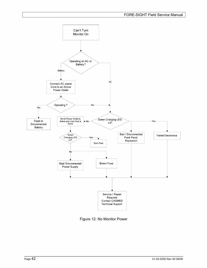
Figure 12: No Monitor Power

FORE-SIGHT Field Service Manual
21-02-0250 Rev 00 09/09 Page 43
Figure 13: Power up Response

FORE-SIGHT Field Service Manual
Page 44 21-02-0250 Rev 00 09/09
Figure 14: SctO2 Trouble Shooting

FORE-SIGHT Field Service Manual
21-02-0250 Rev 00 09/09 Page 45
ERROR MESSAGES The FORE-SIGHT MC-2000 Series Monitor displays a variety of messages to aid the user in monitor operation. If a troubleshooting message is displayed during a measurement, follow the actions listed to correct the situation. If the monitor does not turn on, or exhibits a flashing display and failure to operate, the battery is most likely below the Dead Battery point. Connect the monitor to a power source (AC Line Power) and allow it to charge for four (4) hours. If the monitor is in need of repair, it must be referred to the appropriate service personnel. Service performed by unauthorized personnel could be detrimental to the monitor and will void the warranty. For service, contact your distributor or CAS Medical Systems, Inc.
SctO2 USER MESSAGES If the accuracy of any measurement does not seem reasonable, first check the patient’s vital signs by an alternate method. When no monitor cable is attached to the monitor, the %SctO2 numeric will be dashed and the text “L SctO2 M cable disconnect” or “R SctO2 M cable disconnect” is displayed in message area. Press the SILENCE/RESET pushbutton. The monitor silences the audible alarm tone, and the message is removed from the message area. When a monitor cable is attached, but no sensor is attached to the monitor cable, the %SctO2 numeric will be dashed and the text “L SctO2 P cable disconnect” or “R SctO2 P cable disconnect” is displayed in the message area. Press the SILENCE/RESET pushbutton. The monitor silences the audible alarm tone, and the message is removed from the message area. If the message “L SctO2 cable/sensor error” or “R SctO2 cable/sensor error” appears in the message area, verify that the monitor cable and sensor are not defective. Press the SILENCE/RESET pushbutton. The monitor silences the audio alarm tone, but the message remains. Remove the defective cable/sensor and replace it with a working cable/sensor. Should any of the above problems persist, contact your distributor or CAS Medical Systems.
FORE-SIGHT Field Service Manual
Page 46 21-02-0250 Rev 00 09/09
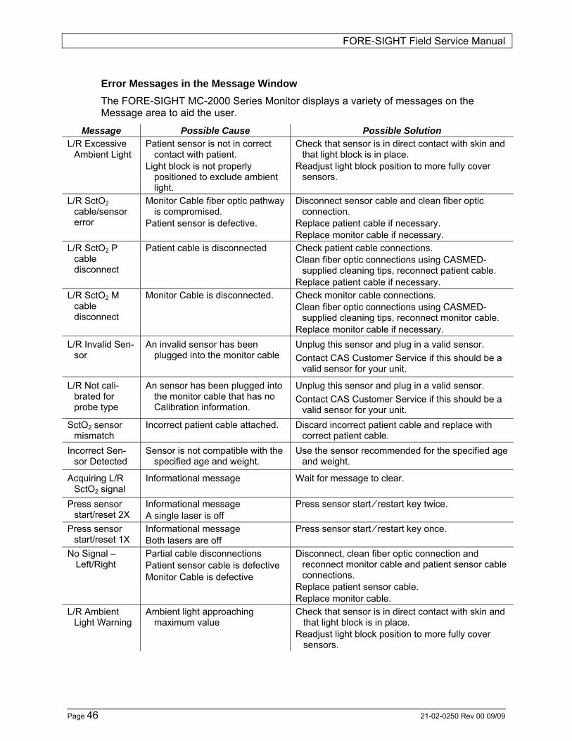
Error Messages in the Message Window The FORE-SIGHT MC-2000 Series Monitor displays a variety of messages on the Message area to aid the user.
Message Possible Cause Possible Solution L/R Excessive
Ambient Light Patient sensor is not in correct
contact with patient. Light block is not properly
positioned to exclude ambient light.
Check that sensor is in direct contact with skin and that light block is in place.
Readjust light block position to more fully cover sensors.
L/R SctO2 cable/sensor error
Monitor Cable fiber optic pathway is compromised.
Patient sensor is defective.
Disconnect sensor cable and clean fiber optic connection.
Replace patient cable if necessary. Replace monitor cable if necessary.
L/R SctO2 P cable disconnect
Patient cable is disconnected Check patient cable connections. Clean fiber optic connections using CASMED-
supplied cleaning tips, reconnect patient cable. Replace patient cable if necessary.
L/R SctO2 M cable disconnect
Monitor Cable is disconnected. Check monitor cable connections. Clean fiber optic connections using CASMED-
supplied cleaning tips, reconnect monitor cable. Replace monitor cable if necessary.
L/R Invalid Sen-sor
An invalid sensor has been plugged into the monitor cable
Unplug this sensor and plug in a valid sensor. Contact CAS Customer Service if this should be a
valid sensor for your unit.
L/R Not cali-brated for probe type
An sensor has been plugged into the monitor cable that has no Calibration information.
Unplug this sensor and plug in a valid sensor. Contact CAS Customer Service if this should be a
valid sensor for your unit. SctO2 sensor
mismatch Incorrect patient cable attached. Discard incorrect patient cable and replace with
correct patient cable. Incorrect Sen-
sor Detected Sensor is not compatible with the
specified age and weight. Use the sensor recommended for the specified age
and weight.
Acquiring L/R SctO2 signal
Informational message Wait for message to clear.
Press sensor start/reset 2X
Informational message A single laser is off
Press sensor start ⁄ restart key twice.
Press sensor start/reset 1X
Informational message Both lasers are off
Press sensor start ⁄ restart key once.
No Signal – Left/Right
Partial cable disconnections Patient sensor cable is defective Monitor Cable is defective
Disconnect, clean fiber optic connection and reconnect monitor cable and patient sensor cable connections.
Replace patient sensor cable. Replace monitor cable.
L/R Ambient Light Warning
Ambient light approaching maximum value
Check that sensor is in direct contact with skin and that light block is in place.
Readjust light block position to more fully cover sensors.

FORE-SIGHT Field Service Manual
21-02-0250 Rev 00 09/09 Page 47
Message Possible Cause Possible Solution
L/R Signal out of Range
Sensor on inappropriate object Remove sensor from inappropriate object and place on patient forehead.
L/R Check tissue under sensor
Tissue under sensor may have fluid accumulation/edema
Check patient for scalp edema. When tissue condition returns to normal range (i.e.,
significant edema is no longer present), alarm message will disappear and SctO2 measurement will return.
Dead Battery Battery needs to be recharged. Plug unit into outlet. Internal Temp
Error Monitor is over operating
temperature range. Shut down monitor and contact CASMED customer
service. Power Failure External power interruption or
disconnected power cord. Applies only to units w/o batteries.
Press the alarm silence button to clear the message or turn monitor off and on again.
Set Clock Clock has not been set. Set date and time via Setup > Set Time & Date… Clock Battery Clock battery needs to be
replaced. Contact CASMED customer service.
Low Battery Battery needs to be recharged. Plug unit into outlet. Loss of AC
Power AC power loss, Unit operating on
Battery power. Plug unit into outlet
System Memory Nearly Full
Data storage is near capacity. Save your data and clear the current data by selecting new patient
System Memory Full
Data storage has reached capacity
Data is no longer being stored. Save your data and clear the current data by selecting new patient
Internal Temp Warning
Monitor is beginning to overheat. Check for free flow of temperate air around monitor. Move monitor away from wall or other obstruction. Move it to a cooler area. If condition persists,
contact CASMED customer service. Battery Supply
Inoperative Battery Fuse missing or blown, or
battery harness disconnected. Install Battery fuse. Contact CASMED customer service.
System Error - ## - ###
Internal component failure. Refer to Table 4 for additional details.
Contact CASMED customer service.
Table 3: User Messages

FORE-SIGHT Field Service Manual
Page 48 21-02-0250 Rev 00 09/09
A System Error indicates an error was detected by the monitor. The following table can be used to determine the source and type of error that occurred.
2 Digit (source) 3 Digits (Error Type)
01 System Controller board 02 PIC 03 Left NSAM board 04 Right NSAM board
001 Unknown 002 Internal software 003 Low NVRAM battery 004 Serial Communications timeout with NSAM Board 005 Checksum error with NSAM Board 006 Serial Communications timeout with Masimo Board 007 Checksum error with Masimo Board 008 Serial Communications error with Masimo Board 009 PIC jumper in BDM mode 010 Fan rotor is jammed 011 Program stack max limit reached/exceeded 012 Memory pool max limit reached/exceeded 013 NSAM message too big for buffer 014 NSAM has sent a bad status 015 Detected unexpected Interrupt 016 Detected FATAL error 017 NSAM communication message size mismatch 018 Battery fuse or battery is missing / bad battery
connection 019 Message pool reaches limit
Table 4: System Error Definition

FORE-SIGHT Field Service Manual
21-02-0250 Rev 00 09/09 Page 49
9 MAINTENANCE PROCEDURES
INTRODUCTION Preventive maintenance of the monitor is an important function that should be performed routinely to ensure safe and efficient monitor operation. The following maintenance intervals are recommended:
• Monitor: No user calibration is required.
• Batteries: Should be replaced every 2 years.
This section discusses the tests used to verify performance during routine maintenance. All tests can be performed without removing the FORE-SIGHT MC-2000 Series Monitor’s cover.
If the FORE-SIGHT MC-2000 Series Monitor fails to perform as specified in any test, repairs must be made to correct the problem before the monitor is returned to the user.
Contact CAS Medical Systems, Inc. or your local distributor.
Equipment Required To test the SctO2
• SctO2 Simulator (CAS p/n 01-06-0031)
To perform Electrical Safety
• Electrical Safety Analyzer
Data Sheet This procedure uses a Data Sheet as the record for verifying monitor performance. Once the procedure is completed, CAS recommends the Data Sheet be kept with the respective monitor’s Device History Record should verification of monitor performance be questioned.
The DATA SHEET can be found on page 53.
Battery Charge Perform the following procedure to fully charge the battery.
1) Connect the monitor to an AC power source.
2) Verify the monitor is “OFF” and that the AC Line Indicator LED is lit.
3) Charge the battery for at least four (4) hours.

FORE-SIGHT Field Service Manual
Page 50 21-02-0250 Rev 00 09/09
Turning the FORE-SIGHT MC-2000 Series Monitor “On” Perform the following procedure to verify the FORE-SIGHT MC-2000 Series Monitor powers “ON” properly.
1) Connect the monitor to an AC power source.
2) Verify the monitor is “OFF” and that the AC Line Indicator LED is lit.
3) Do not connect any cables to the monitor.
4) Press the ON/OFF (STANDBY) pushbutton on the front panel to turn the monitor “ON”.
Upon applying power to the monitor, the FORE-SIGHT MC-2000 Series Monitor displays an animated start-up splash screen and conducts an electronic Power On Self-Test (POST) to ensure that its internal circuits are functioning properly.
NOTE:
The user should use the Power On Self Test as a verification tool that all front panel visual indicators and the audio are functioning properly.
Displaying the Date and Time Perform the following procedure to verify the date and time is set correctly.
1) Verify the monitor displays the date and time (in 24 Hr. format), in the bottom right area of the main display.
Alarm Audio Perform the following procedure to verify the audio range for the Alarm volume.
1) Turn the rotary control knob to select the Setup menu.
2) Press the rotary control knob to open the Setup menu.
3) Press the rotary control knob a second time to open the SctO2 Limits dialog.
4) Navigate to the Volume selection, click and adjust the volume and verify the volume of the generated tones change correspondingly.
5) Select the Done button and press the rotary control knob to save your changes. Select the Cancel button to cancel your changes.
NOTE:
The Alarm Volume level cannot be set to “OFF”.

FORE-SIGHT Field Service Manual
21-02-0250 Rev 00 09/09 Page 51
OXIMETRY SIMULATION CHECK The oximeter is factory calibrated to determine the percentage of regional hemoglobin oxygen saturation of blood in the brain. No user calibration is required.
SctO2 Simulator Check 1) Enter the FORE-SIGHT monitor’s “HELP” screen.
2) Select “CAS login” and enter the password BIOMED. Select the DONE button when finished.
3) Re-enter the FORE-SIGHT monitor’s “HELP” screen.
4) Select “EXTERNAL SIMULATOR TEST…” from the menu.
5) Plug the simulator into the Left and Right monitor cables.
6) Press “SENSOR START / RESTART” keypad switch.
7) Expected Results: both channels are “GREEN” (Pass) which indicates normal operations.
8) Faults: Either channel “RED” (Fail). Swap cables to identify if the fault follows the cable. If remains “RED”, contact CAS Service.
ELECTRICAL SAFETY CHECKS
WARNING: DO NOT touch the monitor when performing these tests.
Leakage 1) Disconnect all accessories from the monitor.
2) Plug the AC power cord from the FORE-SIGHT MC-2000 Series Monitor into the Electrical Safety Analyzer.
3) Turn the FORE-SIGHT MC-2000 Series Monitor “ON”.
4) Perform a Leakage Check per the electrical safety analyzer’s instructions. Verify the monitor’s leakage to be less than 100 micro-amps.
This concludes the testing to the FORE-SIGHT MC-2000 Series Monitor.

FORE-SIGHT Field Service Manual
Page 52 21-02-0250 Rev 00 09/09
Page intentionally left blank

FORE-SIGHT Field Service Manual
21-02-0250 Rev 00 09/09 Page 53
DATA SHEET
Date: Tested By:
FORE-SIGHT MC-2000 Series Monitor
Distributor / Hospital: Monitor Type:
Address: Monitor Serial Number:
City:
State:
Zip code:
Comments:
Page 1 of 2

FORE-SIGHT Field Service Manual
Page 54 21-02-0250 Rev 00 09/09
DATA SHEET (cont.)
Battery Charge Verify the AC Line Indicator LED is lit. Pass ( ) Fail ( )
Turning the FORE-SIGHT MC-2000 Series Monitor “ON” Monitor displays Animated Splash screen for 5 second. Pass ( ) Fail ( )
Displaying the Date and Time Verify the monitor’s Date and Time are set correctly. Pass ( ) Fail ( )
Alarm Audio Verify the Alarm Volume can be adjusted to one of five levels. Pass ( ) Fail ( )
SctO2 Simulator Check Verify Left channel results. Pass ( ) Fail ( ) Verify Right channel results. Pass ( ) Fail ( )
Leakage Verify the monitor’s leakage to be less than 100 micro-amps. Pass ( ) Fail ( )
Page 2 of 2

FORE-SIGHT Field Service Manual
21-02-0250 Rev 00 09/09 Page 55
10 SERVICE PROCEDURES
INTRODUCTION CAUTION:
Removal of the “Warranty Void If Removed” sticker will void any warranty the monitor may have. DO NOT remove the top cover. Only personnel authorized to do so by CAS Medical Systems, Inc., should repair the monitor.
Tools Required
• Small, Flat blade, screwdriver
AC FUSE NOTE:
The FORE-SIGHT MC-2000 Series Monitor models have multiple fuses located inside the monitor. These fuses are not user replaceable.
The FORE-SIGHT MC-2000 Series Monitor has a dual fuse AC power input receptacle. Both AC lines are fused.
The FORE-SIGHT MC-2000 Series Monitor has a single fuse DC receptacle for the internal batteries.
CAUTION: The Battery fuse must be installed for the unit to operate with the internal batteries. If the unit is not to be used for periods greater than 1 week, the battery fuse should be removed.
CAUTION: For continued protection against fire hazard, replace only with identically rated fuses. Refer to the SPARE PARTS section on page 63 and the POWER section on page 66.
NOTE: A fuse may need to be replaced if the monitor is plugged into an electrical outlet but the AC Line Indicator LED is not illuminated.
WARNING: Before changing the fuse, unplug the power cord.
To replace the AC Power fuses, proceed as follows (Refer to Figure 4: Rear Panel View):
1) Turn the monitor off and disconnect the power cord.
2) Using a small screw driver, open the fuse cover on the AC Fuse Compartment.
3) Using a small screw driver, pull out the red fuse holder from the AC Fuse compartment.
4) Remove the suspect fuse.
FORE-SIGHT Field Service Manual
Page 56 21-02-0250 Rev 00 09/09
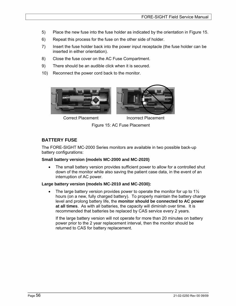
5) Place the new fuse into the fuse holder as indicated by the orientation in Figure 15.
6) Repeat this process for the fuse on the other side of holder.
7) Insert the fuse holder back into the power input receptacle (the fuse holder can be inserted in either orientation).
8) Close the fuse cover on the AC Fuse Compartment.
9) There should be an audible click when it is secured.
10) Reconnect the power cord back to the monitor.
Correct Placement Incorrect Placement
Figure 15: AC Fuse Placement
BATTERY FUSE The FORE-SIGHT MC-2000 Series monitors are available in two possible back-up battery configurations:
Small battery version (models MC-2000 and MC-2020)
• The small battery version provides sufficient power to allow for a controlled shut down of the monitor while also saving the patient case data, in the event of an interruption of AC power.
Large battery version (models MC-2010 and MC-2030):
• The large battery version provides power to operate the monitor for up to 1½ hours (on a new, fully charged battery). To properly maintain the battery charge level and prolong battery life, the monitor should be connected to AC power at all times. As with all batteries, the capacity will diminish over time. It is recommended that batteries be replaced by CAS service every 2 years.
If the large battery version will not operate for more than 20 minutes on battery power prior to the 2 year replacement interval, then the monitor should be returned to CAS for battery replacement.

FORE-SIGHT Field Service Manual
21-02-0250 Rev 00 09/09 Page 57
Disconnecting the Battery Note: Some units may be equipped with an automatic Battery Cut-Off circuit that will disconnect the battery when they are not being charged. Please contact our Customer Service department to determine if your unit has this feature.
If this feature is installed and the monitor will not be used for more than 1 week, follow the procedure below to store the unit (Refer to Figure 4: Rear Panel View):
1) Charge the unit overnight (16 hours minimum) prior to storage.
2) Using a screwdriver, gently press in and turn the locking tab counterclockwise to release (see Figure 16a)
3) Gently slide the fuse holder tray out of the receptacle as far as it will go - Do not remove the fuse.
4) Gently slide the fuse holder tray back into the receptacle.
5) Using a screwdriver, gently press in and turn the locking tab clockwise to secure (see Figure 16a)
This action will disconnect the battery and prolong the life of the battery while the unit is being stored.
If this feature is NOT installed and the monitor will not be used for more than 1 week, follow the procedure below to store the unit:
1) Charge the unit overnight (16 hours minimum) prior to storage.
2) Using a screwdriver, gently press in and turn the locking tab counterclockwise to release (see Figure 16a).
3) Gently slide the fuse holder tray out of the receptacle as far as it will go.
4) Remove the fuse completely from the fuse holder tray.
5) Gently slide the fuse holder tray back into the receptacle. Store the fuse.
6) Using a screwdriver, gently press in and turn the locking tab clockwise to secure (see Figure 16a).
7) After storage, repeat the above instructions in reverse, inserting the fuse back into the monitor.
Note: To charge the battery, AC power must be applied.

FORE-SIGHT Field Service Manual
Page 58 21-02-0250 Rev 00 09/09
Replacing the Battery Fuse To replace the Battery fuse, proceed as follows (Refer to Figure 4: Rear Panel View):
1) Turn the monitor off and disconnect the power cord.
2) Gently press in and turn the locking tab counterclockwise to release (see Figure 16a).
3) Gently slide the fuse holder tray out of the receptacle as far as it will go.
NOTE: The fuse holder tray is not designed to be removed from the fuse holder. DO NOT attempt to pull the fuse holder tray out of the fuse holder or permanent damage to the fuse holder may occur.
4) Remove the fuse from the fuse holder tray (see Figure 16b).
5) Place a new fuse directly into the fuse holder tray (see Figure 16c).
6) Gently slide the fuse holder tray back into the receptacle.
7) Gently press in and turn the locking tab clockwise to secure.
8) Re-connect the power cord.
CAUTION:
For continued protection against fire hazard, replace only with identically rated fuses. Refer to the SPARE PARTS section on page 63 and theError! Reference source not found.Error! Reference source not found. Error! Reference source not found.Error! Reference source not found.Error! Reference source not found.Error! Reference source not found.POWER section on page 66.
NOTE:
DO NOT apply excessive force when removing or installing the fuse holder into the receptacle.
NOTE:
When the battery fuse is re-installed, the monitor may automatically turn “ON”.
Figure 16: Battery Fuse Placement
a b c

FORE-SIGHT Field Service Manual
21-02-0250 Rev 00 09/09 Page 59
CALLING CASMED for an RMA NUMBER
In order to have a monitor returned to CASMED for repair, there must be an RMA number (Return Merchandise Authorization) assigned by CASMED. Please have all information on the Service and Repair Questionnaire available.
In order to issue an RMA number, CASMED will need
- Model Type
- Serial Number - Customer ID
- P.O. number may be necessary if the customer has NET 30 terms and the repair is billable. Please note that a customer can use a P.O. to approve a certain amount (e.g., PM service for $800.00) and CASMED will call for approval if the repair exceeds the amount.
- Issue with the unit should be as specific as possible. The more detail available, the more accurately we will be able to “pin point” the issue. Please see the Service and Repair Questionnaire for guidelines of information needed.
- Once the RMA number is given to the customer, it is important that they keep the number for their reference.
- All RMA items are sent to the address below:
CAS Medical Systems Attn: RMA # 32 East Industrial Road Branford, CT 06405

FORE-SIGHT Field Service Manual
Page 60 21-02-0250 Rev 00 09/09
Service and Repair Questionnaire
When calling technical support/customer service, please have as much as possible of the following infor-mation available: 1. Contact person and location Name Title
Institution Phone Pager Email 2. Pre-Amp cables serial numbers 3. Software/Firmware revision levels
(available from “Help” menu, ‘‘About” selection) • Monitor Serial Number(s)
(available from rear panel label & “Help” menu, “About” selection) • Software Version • PIC Version • Left NSAM Boot • Left NSAM Version • Right NSAM Boot • Right NSAM Version (available from “Help” menu, “About” selection)
4. Date & time (local) of each occurrence 5. Detailed description of fault • Alerts or Error Messages presented • Description of other fault symptom(s)
6. Monitor operation when fault occurred • Mode of operation when fault occurred
• Accessories connected when fault occurred
(e.g., pre-amp cables, sensors, printer, USB drive, etc.) • Power source when fault occurred
(e.g., battery, 120 VAC 60Hz, 240 VAC 50 Hz, etc.) • Length of time in operation before fault occurrence
(e.g., 1 hr, 10 minutes, at power-on) 7. Events (if any) during or immediately prior to fault occurrence • Monitor: Connecting or disconnecting
accessories, changing mode of operation or display, changing power source, etc.
• External events or other equipment that seemed associated with the fault.

FORE-SIGHT Field Service Manual
21-02-0250 Rev 00 09/09 Page 61
CUSTOMER CARE PLAN
Preventative Maintenance, Parts and Labor Repairs, and Exchange items programs, to insure maximum uptime for your product.
• Suggested preventative maintenance (PM) cycle for this product is 2 years. Below are the PM services provided at this service cycle:
Flat rate list pricing.
1. Visual inspection of unit inside and out.
2. Update hardware and software as required through ECN changes. Maintenance/Error updates.
3. Battery Replacement.
4. Fan filter replaced.
5. Assessment of all Accessories sent in with monitor.
6. Calibration and or adjustments to monitor.
7. SctO2 functional test.
8. Front panel receptacles cleaning and or replacement if needed.
9. Monitor Preamp Cables tested and connections cleaned.
10. Monitor Safety Leakage Check/ Hi Pot Test.
11. Update labeling where needed.
12. Final Factory Test Procedure.
13. Cleaning
14. QA Inspection

FORE-SIGHT Field Service Manual
Page 62 21-02-0250 Rev 00 09/09
Parts replaced if needed at no additional charge. Parts replacements to be determined by repair technician.
1. Front panel key switch Any circuit boards, which need to be replaced due to malfunction, will have an additional charge on the PM Price. Customers will be provided with an estimate prior to repairs. PM Price also does not apply to units and accessories that have been misused or damaged.
• After warranty factory depot repair parts and labor repairs also provided, Estimates provided upon request. Sensor Contract Customers excluded.
• Exchange Items include Pre-amp box as an assembly. Refurbished
assemblies to help reduce replacement cost from new product.
• Loaners are available for customers that request them.
• Customers without proper packaging for shipping will be sent an empty box for transport of unit.
NOTE: No other extended warranty applies to this product or PM program. NOTE: Parts replaced for service repairs are covered for 90 days from point of repair.

FORE-SIGHT Field Service Manual
21-02-0250 Rev 00 09/09 Page 63
11 SPARE PARTS
Part Number Description
01-02-0384 Power Cord, Intr., 220 VAC 01-02-0385 Power Cord, Australian 01-02-0386 Power Cord, Intr., 240 VAC 01-02-0395 Power Cord, USA 01-06-0005 Monitor Cable with Pre-Amp 01-06-0031 SctO2 Simulator 01-06-0035 Biomedical Cleaning Kit 01-06-0237 Adapter Plate (for use with roll stands or arms)
09-01-0032 Fuse, 8 Amp 09-01-0033 Fuse, 3.15 Amp 25-01-0124 Cable Bundler

FORE-SIGHT Field Service Manual
Page 64 21-02-0250 Rev 00 09/09
Page intentionally left blank

FORE-SIGHT Field Service Manual
21-02-0250 Rev 00 09/09 Page 65
12 SPECIFICATIONS SctO2 MEASUREMENT Method: Modified Beer-Lambert Law Near Infrared Spectroscopy (NIRS) at
wavelengths: 690, 780, 805, and 850 nm Information output: Absolute cerebral tissue oxygenation saturation (SctO2) Measurement range: 0 to 99% Accuracy: Accuracy not determined < 45%. Monitor may not be accurate at
saturations below 45%. Large Sensors: 45% to 95%: ±3.7% to 1 standard deviation
Medium Sensors: 50% to 99%: ±4.9% to 1 standard deviation Small Sensors: 50% to 99%: ±5.0% to 1 standard deviation
Display resolution: Increments of 1 Data rates: Acquisition ≤ 100 Hz, numeric display = .5 Hz
LASER INFORMATION EQUIPMENT MANUFACTURE INFORMATION ( DATA SHEET ) ABOUT THE COMPONENT
CONTAINING LASER Type designation: BM4-690-779-808-850-10SM
4-Wavelength Beam Combiner with Power Monitor Max Output Power: 20 mW Pulse time: 3.1 ms
PATIENT ALARMS Adjustable alarms: High and low alarms for left, right and differential SctO2 values Alarm indicators: • Left & Right Visual
• Audible • Text in alarm message window
High Priority Alarms: 53db (Fast A) @ 1m directly in front of monitor
Audible sound pressure 100% Volume
Medium Priority Alarms: <52db (Fast A) @ 1m directly in front of monitor
Patient Parameter Low Limit High Limit Left SctO2 0 to 93% 5 to 98% Right SctO2 0 to 93% 5 to 98% Differential SctO2 N/A 1 to 50%
Each patient parameter may also be selected “OFF” individually. SctO2 alarm settings are in increments of 1. Low limits cannot be set above the associated high limit. High limits cannot be set lower than the associated low limit. There is a minimum difference of 5 between the Low and High limit values at any time.

FORE-SIGHT Field Service Manual
Page 66 21-02-0250 Rev 00 09/09
DISPLAY Display: LCD display of measurement results, instructions, troubleshooting
messages, waveforms, and signal strength bar. Numerics: SctO2 (from left, right or average of left and right channels) Trace: 1 corresponding to associated SctO2 numeric value Views: 15 or 30 minute, 1, 2, 3, 4, 8 or 24 hour Events: May be placed anywhere on trace area.
PHYSICAL DIMENSIONS AND WEIGHT H × W × D: (without feet) 8 in. × 8 in. × 13 in.
20.3 cm × 20.3 cm × 33.0 cm Weight (MC-2010): 21.9 lbs (9.9 kg)
OPERATING ENVIRONMENT Operating temperature: 10–40°C (50–104°F) Humidity: 30–75% RH, non-condensing Altitude: 10,000 to –1,000 ft (680 to 1060 hPa)
Monitors may not meet performance specifications if stored or used outside temperature and humidity ranges. When moving the monitor from a storage location, wait at least one hour prior to use to allow the monitor to adjust to room temperature.
STORAGE/TRANSPORT ENVIRONMENT Storage/transport
temperature: –20 to 60°C (–4 to 149°F)
Humidity: 15–95% RH, non-condensing Altitude: 10,000 to –1,000 ft (680 to 1060 hPa)
POWER External power:
AC: 100–240 VAC, 50/60 Hz, 1.5A Fuse rating: T3.15AH250V (two provided)
Chassis leakage current: 100 µA (maximum) Battery: 2 sealed, lead-acid batteries
Fuse rating: F8AL250V (one provided) Charge Time: 16 hours (with unit on)
Operating Time: 1½ hr (minimum)

FORE-SIGHT Field Service Manual
21-02-0250 Rev 00 09/09 Page 67
SERIAL INTERFACE Interface type: Bi-directional serial communication Speed: User-programmable Signal level: RS-232C Data length: 8 bits Start bit: 1 bit Stop bit: 1 bit Parity: None Flow control: None
STANDARDS Units comply with the following requirements: CE marking according to Directive 93/42/EEC IEC 60601-1, EN 60601-1-2 IEC 60601-1-1, IEC 60601-1-4, IEC 60601-1-8 UL classified: UL 60601-1, CAN/CSA C22.2 No. 601.1-M90 IEC 60825-1
All units covered by U.S. patents 6,456,862; 7,047,054; 7,072,701 Other patents pending
FORE-SIGHT Field Service Manual
Page 68 21-02-0250 Rev 00 09/09
Notes: