force/torque display for - nasa · force/torque display for space teleo control experiments and...
TRANSCRIPT

FORCE/TORQUE DISPLAY FOR SPACE TELEO CONTROL EXPERIMENTS AND EVALUATION
Kevin Corker 10 Moulton Street
Bol t , Beranek and Newman, Inc. Cambridge, Massachusetts 02238
Anta1 Bejczy and Barry Rappaport Jet Propuls ion Laboratory
4800 Oak Grove Drive Pasadena, C a l i f o r n i a 91109
ABSTRACT
E x p e r i m e n t s were pe r fo rmed a t t h e Johnson Space C e n t e r (JSC), Manipulator Development F a c i l i t y u s i n g t h e f u l l s c a l e S h u t t l e Remote Manipulator System (SRMS) t o eva lua te t he effect of v i s u a l p r e s e n t a t i o n through p e r s p e c t i v e d i s p l a y of t h e or thogonal f o r c e s and to rques sensed a t t h e m a n i p u l a t o r end e f f e c t o r . T h e e x p e r i m e n t s i n v e s t i g a t e d t h e e f f e c t o f t h e d i s p l a y i n f o r m a t i o n on t h e management o f f o r c e s and t o r q u e s g e n e r a t e d d u r i n g p a y l o a d b e r t h i n g and dep loymen t , as w e l l as s imula t ed s a t e l l i t e module change-out opera t ions . The e v a l u a t i o n a l s o addressed (i) i s s u e s o f d i s p l a y format , inc luding: fo rce / to rque s c a l i n g , po in t o f r e s o l u t i o n , and d i s p l a y mixing w i t h video genera ted imagery, and (ii) t a s k related v a r i a b l e s of payload s i z e , a l t e r n a t i v e sou rces Of guidance in fo rma t ion , and con t ro l mode.
T h i s p a p e r b r i e f l y p r e s e n t s t h e r e s u l t s of a f i r s t - p a s s i n f o r m a l a n a l y s i s of t he analog, s t r i p char t - recorded data from these e v a l u a t i o n tests. The resul ts provide a r e l a t i v e measure of improvement i n f o r c e management t h r o u g h t h e u s e of s u c h a d i s p l a y , as w e l l a s i n f o r m a t i o n regard ing t h e impact of d i s p l a y v a r i a b l e s and t a s k demands on ope ra to r performance.
1.0 INTRODUCTION
Two exper iments were performed a t t h e JSC Manipulator Development F a c i l i t y u s i n g t h e f u l l - s c a l e S h u t t l e R M S and the J P L two hundred pound r a n g e f o r c e / t o r q u e (F/T) s e n s o r , f o u r - c l a w end e f f e c t o r , and a pe r spec t ive v i s u a l d i s p l a y o f t he f o r c e s and to rques sensed a t the end- e f fec tor . The equipment used i n these tests, w i t h the excep t ion of t h e p e r s p e c t i v e d i s p l a y s y s t e m , a r e d e s c r i b e d i n a p r e v i o u s e v a l u a t i o n r e p o r t by Bejczy and co-workers (1982).
The two e v a l u a t i o n s e s s i o n s provided an assessment of t h e effect of t h e F/T s e n s o r and d i s p l a y s y s t e m on SRMS pe r fo rmance . The f i r s t s e s s i o n i n v e s t i g a t e d ope ra to r handl ing i n large payload ber'thing. The second s e s s i o n d e a l t w i t h s m a l l t o o l h a n d l i n g and s i m u l a t e d module change-out performance. F igu re 1 provides a p lan view of t he payloads, t h e i r s i z e , and l o c a t i o n f o r t h e t e s t s , i n r e l a t i o n t o t h e R o c k w e l l
2 6 . 1
https://ntrs.nasa.gov/search.jsp?R=19860023530 2018-06-28T14:41:46+00:00Z

TASK BOY (PLAN VIEW)
PFTA (PLAN VIM?
PAYLOAD LOCATIONS IN JSC MDF FORCE/TORQUE DISPLAY
Figure 1.
2 6 . 2

Figure l b .
26.3

S h u t t l e p o i n t of r e f e r e n c e (POR) , i.e., 236 i n . f o r w a r d o f and 400 i n . below the o r b i t e r nose point.
The e v a l u a t i o n t a s k s were performed by f o u r JSC personnel who were t r a i n e d and MDF q u a l i f i e d i n the use of t h e s h u t t l e RMS s imula tor . The t e s t s were p e r f o r m e d i n t w o s e s s i o n s e a c h o f one week d u r a t i o n and sepa ra t ed by a s i x month h i a t u s .
1.1
The characterist ics of t h e d i s p l a y format used f o r these e v a l u a t i o n a re p r e s e n t e d h e r e . S i n c e t h e time o f these tests, we h a v e made s u b s t a n t i a l p rogess i n c r e a t i n g a three dimensional pe r spec t ive d isp lay . Th i s d i s p l a y technique i s descr ibed i n t h e f i n a l s e c t i o n of t h i s paper on f u t u r e research e f f o r t s .
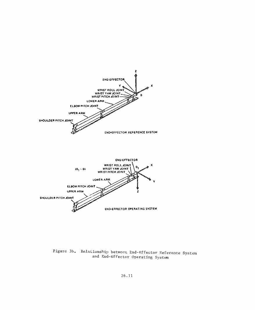
(i> The d i sp lay , p i c tu red i n F igure Two, p re sen t s f o r c e and to rque as f i l l i n g from t h e c e n t e r of t h e s i x a x i s pe r spec t ive frame. The p o i n t Of r e f e rence f o r t he axes can be manipulated i n s o f t w a r e t o correspond t o the c o n t r o l r e f e r e n c e frame of t h e ope ra to r , o r any o t h e r r e fe rence frame deemed a p p r o p r i a t e t o t h e task. I n t he case of t h e PFTA payload, t h e X a x i s r e l a t e s t o t h e f o r e / a f t a x i s o f t h e o r b i t e r , t h e Z a x i s r e f e r s t o t h e e l e v a t i o n i n and o u t o f t h e p a y l o a d bay, and t h e Y a x i s d e s i g n a t e s p o r t / s t a r b o a r d a c r o s s t h e p a y l o a d bay. The t o r q u e s a b o u t t hese axes are des igna ted by f i l l i n g o f t h e p i t c h , r o l l , and yaw frames a s s o c i a t e d w i t h each of t h e t o r q u e s . I n t h e case o f t h e t o o l h a n d l i n g and module change out procedures, t h e d i s p l a y is referenced t o t h e end e f f e c t o r and senso r r e fe rence frame as i l l u s t r a t ed i n F igure 3b.
(ii) The d i s p l a y p r o v i d e s f o r c e and t o r q u e r e a d i n g s t o t h e o p e r a t o r r e f e r e n c e d t o t h e p o i n t o f r e s o l u t i o n ( P O R ) o f t h e PFTA payload, i n t h e first eva lua t ion , and r e fe renced t o t h e sensor r e f e r e n c e frame i n t h e second evaluat ion. (The POR can be va r i ed through s o f t w a r e m a n i p u l a t i o n o f t h e da ta p r o v i d e d by t h e s e n s o r s y s t e m and c a n b e c a l c u l a t e d f o r t h e des i red o p e r a t o r p e r s p e c t i v e , d e p e n d e n t on p a y l o a d geometry,) The POR chosen f o r t h e large payload be r th ing was t h e c e n t e r of g e o m e t r y o f t h e payload . T h i s POR i s f o r w a r d o f t h e c e n t e r of mass of t h e payload t o compensate f o r t he small res idual f r i c t i o n a l f o r c e s a s s o c i a t e d w i t h the payload counterweight system. The MDF counterweight system s e r v e s t o s i m u l a t e ze ro g r a v i t y o p e r a t i o n f o r h igh mass payloads, such as t h e PFTA.
(iii) The "sense" of t h e d i sp l ayed f o r c e s shows the effect of t h e o p e r a t o r ' s c o n t r o l i n p u t on t h e pay load . F o r example , i n t h e case of' PFTA manipula t ion , a r o l l t o p o r t t h a t gene ra t e s con tac t f o r c e s w i t h t h e \ p o r t t r u n i o n s i s d i s p l a y e d a s a n i n c r e a s e d t o r q u e t o p o r t and a n inc reased Z force. The c o r r e c t i v e c o n t r o l a c t i o n t o reduce these f o r c e s and t o r q u e s i s t o r o l l s t a r b o a r d , i.e., t h e o p e r a t o r a c t s a s if t o p u s h t h e e x t e n d i n g d i s p l a y bar t o z e r o , t h e c e n t e r p o i n t . O p e r a t o r s g e n e r a l l y found t h i s " f l y to" arrangement i n t u i t i v e . However, when t h e Payload i s viewed from the a f t cameras t h e sense of the d i s p l a y i n terms of r equ i r ed c o r r e c t i v e a c t i o n i s reversed , T h i s caused some confusion,
2 6 . 4

MESSAGE DISPLAY
AREA
ROLL
FZ
FY
YAW
Figure 2. Display Format
P I T C H
26.5

and argues f o r a d i s p l a y r e fe rence t h a t i s dynamically re ferenced t o t he po in t o f regard o f t h e operator . Experiments and so f tware requi rements f o r s u c h t r a n s f o r m a t i o n s a r e c u r r e n t l y u n d e r c o n s i d e r a t i o n by t h e a u t h o r s e
( i v ) Force/Torque d i s p l a y s c a l i n g proved s e n s i t i v e t o the payload geometry. Because of t h e l a r g e moment arm of t h e PFTA payload, t o rques genera ted a t the bay t run ions s a t u r a t e d t h e torque s c a l i n g more qu ick ly t h a n f o r c e s a b o u t t h e POR. S o f t w a r e d e c o u p l i n g and r e s c a l i n g of t h e t o r q u e d i s p l a y was a c c o m p l i s h e d , b u t t h e r e i s some d a n g e r i n t h i s a p p r o a c h , i n t h a t s e n s o r s a t u r a t i o n may n o t bear a c l e a r r e l a t i o n t o d i s p l a y s a t u r a t i o n . F u t u r e work w i l l seek t o p r o v i d e b o t h s e n s o r and d i s p l a y s a t u r a t i o n scales t o the ope ra to r .
(v) The d i s p l a y s i z e could be reduced t o a l low s p l i t s c reen mixing wi th an ope ra to r selected camera view o f t h e payload.
1.2
The d a t a c o l l e c t e d were (i) t o t a l t a s k t ime, d e f i n e d a s o p e r a t o r c o n t r o l i n i t i a t i o n t o p a y l o a d b e r t h e d and l a t c h e d c o n d i t i o n , (ii) a n a l o g c h a r t r e c o r d i n g o f t h e f o r c e s and t o r q u e s s e n s e d a b o u t three o r t h o g o n a l f o r c e and th ree o r t h o g o n a l t o r q u e axes o f t h e s e n s o r POR d u r i n g t h e b e r t h i n g o p e r a t i o n , and (iii) d i g i t a l r e c o r d i n g o f these f o r c e s and torques. I n t h i s p re l imina ry eva lu t ion , s t a t i s t i c a l a n a l y s i s is precluded by t h e large number of t r ea tmen t c o n d i t i o n s i n r e l a t i o n t o the number o f data p o i n t s ga thered i n t h e ana lys i s . The e v a l u a t i o n was d e s i g n e d t o s u r v e y t h e r e l a t i v e i m p a c t o f t h e p r o v i s i o n of and t h e format o f v i s u a l F/T feedback, r a t h e r than t o e s t a b l i s h s t a t i s t i c a l l y robus t pa rame te r i za t ion of t h a t e f f e c t .
2.0 EVALUATION PROTOCOL
2.1
Task:
The performance r equ i r ed for t h i s e v a l u a t i o n involved be r th ing t h e PFTA payload a f t e r i t was deployed t o a random p o s i t i o n above the paylad bay t r u n i o n guides. The t a sk r e p r e s e n t s t h e p r e c i s i o n placement p o r t i o n of a payload be r th ing task. The b e r t h i n g t a s k was performed t e n times by each s u b j e c t a f t e r f a m i l i a r i z a t i o n and b r i e f i n g r u n s on t h e d i s p l a y c h a r a c t e r i s t i c s . The t e n t e s t t r i a l s were p e r f o r m e d u n d e r v a r i e d feedback and c o n t r o l c o n d i t i o n s as i l l u s t r a t e d i n Table 1. The c o n t r o l p o i n t o f r e f e r e n c e f o r these t e s t s was t h e o r b i t e r c o n t r o l mode, i n which the opera tor c o n t r o l s t h e end e f f e c t o r of t he RMS i n r e l a t i o n t o the s h u t t l e body. T rans l a t ion axes of t he two-handed c o n t r o l l e r refer t o f o r / a f t , po r t / s t a rboa rd , and e l e v a t i o n i n / o u t o f t h e bay. Ro ta t iona l axes o f p i t c h , r o l l and yaw are re fe renced t o these t r a n n s l a t i o n a l axes. (The c o n t r o l mode f o r t h e m a j o r i t y o f t h e tes ts was a r e s o l v e d r a t e control . The except ion t o t h i s was a j o i n t by j o i n t c o n t r o l mode which had its greatest impact i n d r a m a t i c a l l y i n c r e a s i n g r equ i r ed performance
26.6
Control
Camera Display Mod
I PortlStarbrdlStarbrdlElbow I IDigitallF/TI lor
I Aft tForwardt A f t f I I I I I L o ~ d ~ d I h i n t 1
-1- I I _ .A- I I L.-.-. I i I I
1
2
3
4
5
6
7
8
9
10
I "
I "
I
I "
I "
I
I *
I
I
I "
I "
I
I "
I
I "
I
I "
I "
I
I
I
I
I
I
I "
I
I "
I
I
I
I " II
I I I
I I I " I II
I II " I I I
I I 1
I I 1 " I * I I *
I l l
I I 1
I I I
I I I
1 + 1
* I n d i c a t e s sensor a v a i l a b l e o r mode used.
S / S = S p l i t Screen
I I
Table 1. Feedback and Control Conditions f o r PFTA Berthing Experiments
2 6 . 7
time for a l l operat ions.)
Resu l t s :
A v e r y g e n e r a l d i s c u s s i o n of r e s u l t s i s p r e s e n t e d f o r t h i s t a s k . Analysis of the d i g i t a l data, as opposed t o t h e ana log chart record ing , i s b e i n g p u r s u e d w i t h t h e i n t e n t bo d e s c r i b e t h e e f f e c t o f t h e v a r i e d f e e d b a c k v i e w s i n c o n j u n c t i o n w i t h t h e F/T d i s p l a y . A t t h i s p o i n t we w i l l con f ine our d i s c u s s i o n t o t h e management of forces and to rques w i t h and wi thout the v i s u a l d i s p l a y from the sensor .
(i) Force/Torque gene ra t ion :
- P r o v i s i o n of f o r c e / t o r q u e i n f o r m a t i o n v i a t h e v i s u a l d i s p l a y r e d u c e d t h e l o a d s o n t h e PFTA p a y l o a d s and p a y l o a d g u i d e s d u r i n g b e r t h i n g by 30-50 of t h e va lues genera ted wi thou t t h e p rov i s ion o f the d isp lay .
- For those f o r c e s genera ted i n excess of 50% o f t h e dynamic range o f t h e s e n s o r , v i s u a l d i s p l a y of the f o r c e / t o r q u e v a l u e s r e d u c e t h e d u r a t i o n of t he a p p l i c a t i o n of t h a t excess ive force by 60-80
(ii) Task completion time:
- Task c o m p l e t i o n time was most d e p e n d e n t o n t h e i n d i v i d u a l opera tor ' s c o n t r o l s t r a t e g y . The d i r e c t i o n s stressed both accuracy and speed i n t a s k Completion; however, speed was c o n s i s t e n t l y s a c r i f i c e d t o performance accuracy.
- P r o v i s i o n o f F/T i n f o r m a t i o n s l i g h t l y i n c r e a s e d t h e usua l t a sk c o m p l e t i o n time f o r a g i v e n o p e r a t o r . T h i s was p r o b a b l y due t o t h e r e q u i r e m e n t f o r s h a r e d a t t e n t i o n be tween v i s u a l d i s p l a y s o f p a y l o a d p o s i t i o n and t h e f o r c e / t o r q u e d isp lay .
- S e v e r a l o p e r a t o r s n o t e d t h a t t h e p r o v i s i o n of t h e F/T d i s p l a y e x p e d i t e d t r a j e c t o r y p l a n n i n g i n t h e c a s e o f e x c e s s i v e f o r c e a p p l i c a t i o n . T h e F/T i n f o r m a t i o n c o u l d be u s e d d i a g n o s t i c a l l y t o i d e n t i f y t h e cause of t h e problem and t o provide a basis f o r rep lanning t h e maneuver. T h i s was e s p e c i a l l y t r u e i n t h e case of k e e l t r u n i o n misal ignment; because t h e source of such an e r r o r i s not r e a d i l y v i s u a l ava i lab1 e
- As noted, t h e effect of t h e va r i ed feedback c o n d i t i o n s w i l l be ned through a n a l y s i s of t h e d i g i t a l fo rce / to rque data.
2 .a2
Task :
The t o o l u s e and module c h a n g e o u t t a sk i n v o l v e d m a n i p u l a t i o n of the modules o f t h e t a s k board i l l u s t r a t e d i n F igu re 2. The f l a t screw d r i v e r b l a d e as u s e d t o u n l a t c h t h e box module and r e p l a c e d i n t h e
26 .8

a p p r o p r i a t e r e c e p t i c a l . The module was t h e n grasped, removed and r e inse r t ed . The screw d r i v e r b lade was then r e t r i e v e d and used t o l a t ch t h e module back i n p l ace . The t a s k was p e r f o r m e d i n t h e end e f f e c t o r c o n t r o l mode, i n which the c o n t r o l and d i s p l a y was re ferenced t o the end e f f e c t o r p o s i t i o n , i n d e p e n d e n t o f i t s p o s i t i o n i n t h e s h u t t l e bay. F i g u r e 3b i l l u s t r a t e s t h e c o o r d i n a t e s of t h e end e f f e c t o r r e f e r e n c e frame. Figure I b i l l u s t r a t e s t h e placement of t h e t a s k box i n r e l a t i o n t o t h e s h u t t l e bay.
Resu l t s :
It i s s i g n i f i c a n t t o n o t e t h a t t h r e e o f t h e f o u r s u b j e c t s were unable t o compete the module e x t r a c t i o n task wi thout the p rov i s ion Of v i s u a l f o r c e and torque information.
Seve ra l r e p r e s e n t a t i v e f igures have been a b s t r a c t e d from the ana log performance record t o i l l u s t r a t e t y p i c a l performance p r o f i l e s .
- F i g u r e 4 shows t h e c a l i b r a t i o n s c a l e f o r t h e data r ep resen ted .
- Figures 5a-5b shows the basic e x t r a c t i o n / i n s e r t i o n sequence. The g e n e r a t i o n o f e x c e s s i v e f o r c e s and t o r q u e s i n t h e a b s e n c e o f t h e FIT d i s p l a y i s i l l u s t r a t e d i n 5a. I n f a c t , t h e t r i a l was a b o r t e d when t h e fo rces were s u f f i c i e n t t o damage t h e module du r ing t h e test. Successfu l complet ion o f the same t a sk sequence i s demonstrated i n 5b.
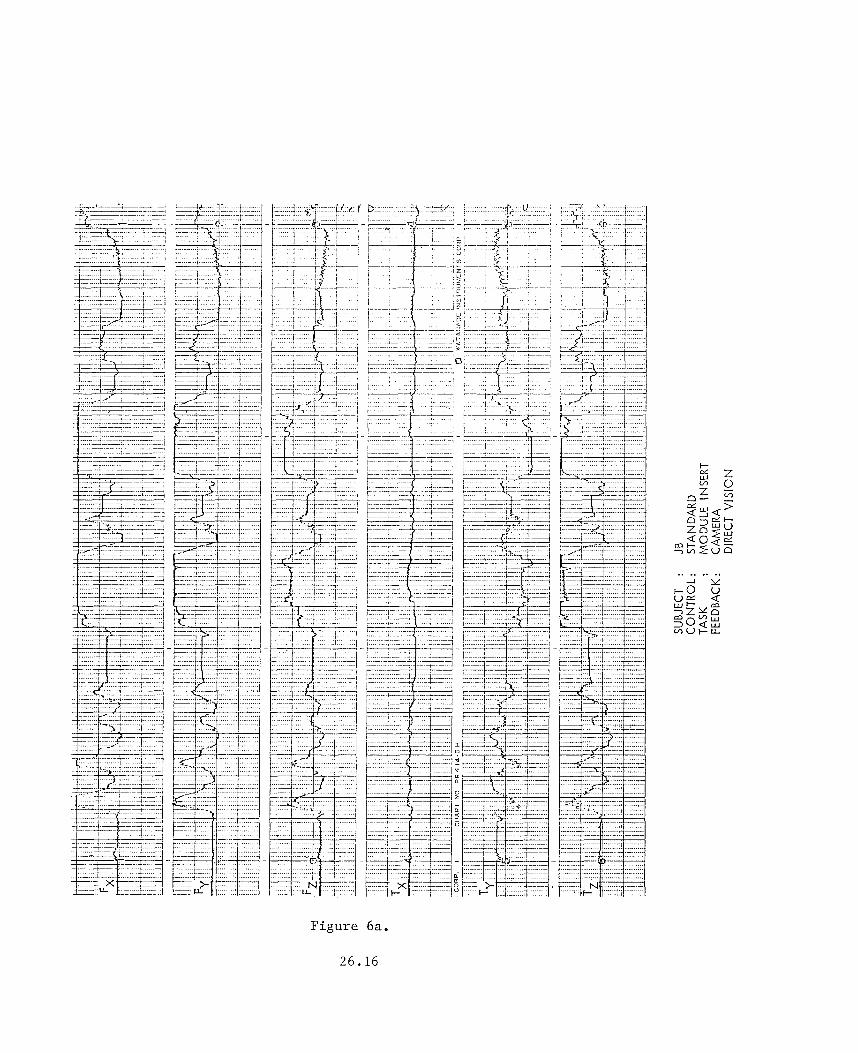
- F i g u r e s 6a-6b p r o v i d e a d i r e c t c o m p a r i s o n of module i n s e r t i o n sequences w i t h and wi thout t h e F/T d isp lay . A comparison o f 6a and 6b i l l u s t r a t e s i n c r e a s e d l e v e l s of f o r c e / t o r q u e gene ra t ion and i n c r e a s e d t a s k comple t ion time f o r the s i n g l e s u b j e c t who was able t o complete the module change out i n t h e absence o f t h e F/T d i sp lay .
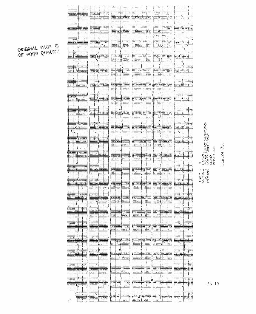
- F i g u r e 7 a p r o v i d e s a d e m o n s t r a t i o n of a jam i n w h i c h modu le e x t r a c t i o n i s a b o r t e d due t o e x c e s s i v e f o r c e i n t h e X and Y a x i s and t o r q u e a b o u t t h e Z a x i s . The d i a g n o s t i c c a p a b i l i t y o f t h e d i s p l a y i s i l l u s t r a t e d i n F igure 7b, i n which, d e s p i t e t h e occas iona l g e n e r a t i o n Of' h i g h f o r c e and t o r q u e v a l u e s , t h e s u b j e c t i s a b l e t o s u c c e s s f u l l y complete t h e module e x t r a c t i o n .
- Figure 8a-8b shows success fu l f o r c e management i n t h e t o o l use sequence of the t a s k as a f u n c t i o n of t h e p rov i s ion of t h e f o r c e / t o r q u e d i sp lay .
3.0 FUTURE RESEARCH EFFORTS
One o f t h e m a j o r c o n c e r n s i n t h e p r e s e n t a t i o n o f f o r c e / t o r q u e i n f o r m a t i o n is the speed vs. cogn i t ive in fo rma t ion t r ansmiss ion dilemma. I n o t h e r words, i t i s t h e dilemma of t r y i n g t o t r a n s f e r t o t h e o p e r a t o r as much i n f o r m a t i o n as f a s t as p o s s i b l e wi thout having a degrada t ion Of performance. Th i s i n fo rma t ion should be presented s o t h a t t h e o p e r a t o r can c o g n i t i v e l y understand and u t i l i z e it.
26 .9
ORBITER BOOY AXIS SYSTEM
X
I O " . o n )
ORBIT€R ROTATION AXIS SY!iTEM
e?
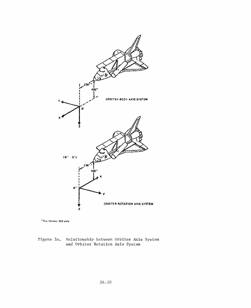
'Figure 3a. Relat ionship between Orbi te r Axis System and Orbi te r Rotat ion Axis System
26.10
SHOULDER PITCH
END EFFECT0
WRIST ROLL x ) l WRIST YAW
WRIST PITCH JOI
SHOULOCR PITCH
WRIST ROLL IO, ’- 01 WRIST YAW JOIN
WRIST PITCH JOINT
Figure 3b. Rela t ionship between End-Effector Reference System and End-Effector Operating System
2 6 . 1 1


B V I A T C F ~ A O E II:STRUtrlCPITS CCRP. i CHERT NO F R ~ 14-8 H
,
SUBJECT : DP CONTROL: STANDARD TASK : MODULE EXTRACTION FEEDBACK : CAMERA
DIRECT VISION
ABORT TRIAL
F i g u r e 5a.
2 6 . 1 3

. . . . . , . . - - r Y L O ( 1
F i g u r e 5b-1.
2 6 . 1 4

F i g u r e 5b-2. 26 .15
........ - J ? L
........
Figure 6a.
26 .16
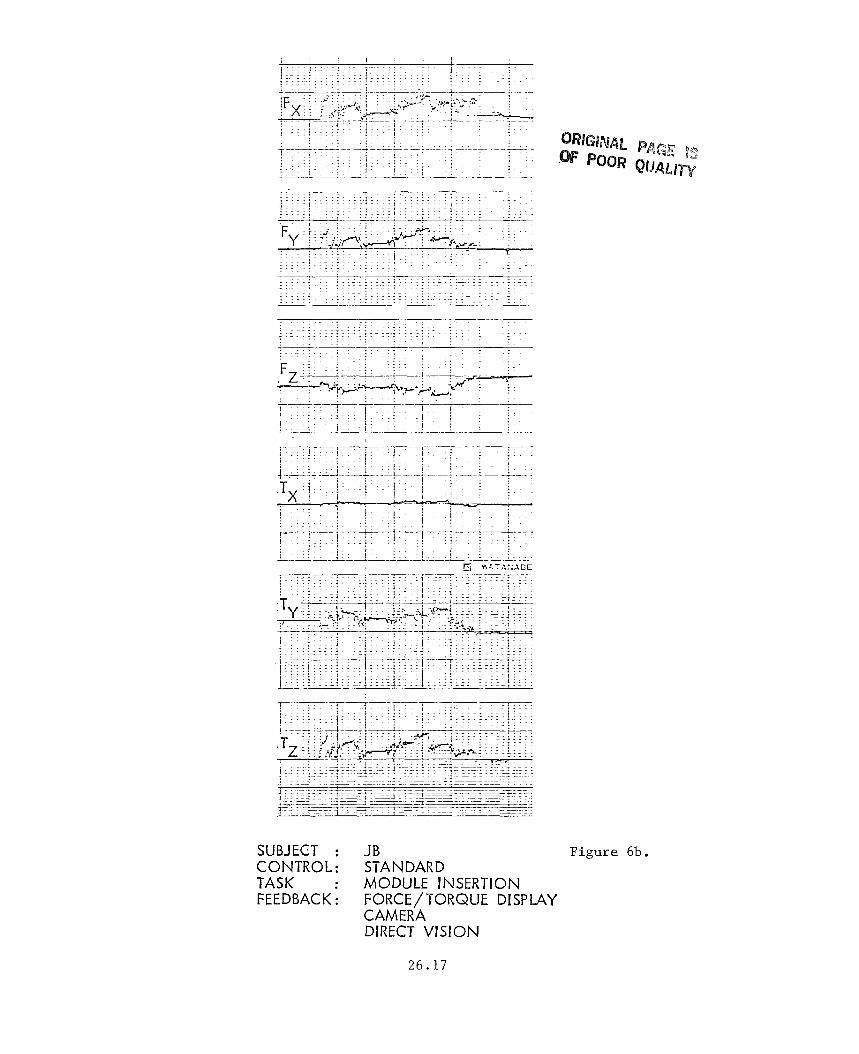
SUBJECT : JB CONTROL: STANDARD TASK : MODULE INSERTION FEEDBACK: FORCE/TORQUE DISPLAY
CAMERA DIRECT VISION
Figure 6b.
26 .17

z 2 > 0
Figure 7a.
26.18
z 0
26.19

26.20

.. x U Q, a w w U
F i g u r e 8b.
2 6 . 2 1

Items for d i s p l a y improvement:
i) T h e d i s p l a y s h o u l d be as smooth as p o s s i b l e . The o p e r a t o r should be concen t r a t ing on t h e i n fo rma t ion p resen t i n the d i sp lay , n o t on the d i s p l a y itself.
Most computer graphics d i s p l a y hardware i s display-bound. The more p i x e l s and po lygons drawn on t h e s c r e e n , t h e s l o w e r t h e p i x e l wri te speed . S i n c e most h a r d w a r e i n t e r n a l g raph ic s s u b r o u t i n e s (d raw r e c t a n g l e s , d raw c i r c l e s ) a r e f a s t e r t h a n s o f t w a r e g e n e r a t e d subrou t ines , i t i s opt imal t o use as many hardware o r i e n t e d commands as poss ib l e .
ii) The d i s p l a y should p re sen t t h e in fo rma t ion i n a n a t u r a l manner ( i a e. , t r u e pe r spec t ive view).
iii) d i s p l a y p a r t s .
C o l o r s h o u l d be used t o enhance c o n t r a s t be tween d i f f e r e n t
The t r u e pe r spec t ive 3-0 Force/Torque d i sp lay :
We have been able t o make progress i n the development of real-time 3-D d i s p l a y s b e c a u s e t h e s u b s t a n t i a l l e a p i n t h e speed o f c u r r e n t computer g raph ic s hardware. The d i s p l a y s w e used a t JSC had a r e f r e s h ra te o f 4 t o 5 h e r t z and t h e r e was a s i g n i f i c a n t s p e e d d i f f e r e n c e between t h e X/Y a x i s and t h e Z ax is . With c u r r e n t d i s p l a y technology, a r e f r e sh r a t e of 30 h e r t z i s e a s i l y a c h i e v e d w i t h much more t r u e and complex d i s p l a y of f o r c e s and to rques (Figure 9).
The t o r q u e s and f o r c e s a r e c o l o r and d i r e c t i o n a l coded. Red i n d i c a t e s a nega t ive f o r c e or to rque and b lue i n d i c a t e s a p o s i t i v e f o r c e or t o r q u e . T h e t o r q u e s f o l l o w t h e r i g h t - h a n d r u l e a round t h e f o r c e axis . The d i s p l a y i s p ro jec t ed i n t r u e perspect ive. The box around the d i s p l a y enhances t he pe r spec t ive image. The r e t i c u l a r marks d i v i d e the f o r c e bars i n t o quar te rs . These marks h e l p t he ope ra to r gauge f o r c e on each axis . T h i s i s true e s p e c i a l l y i n t h e case o f t h e nega t ive z f o r c e a x i s .
We thought about adding a g r i d on the bottom o f t h e box t o enhance t h e p e r s p e c t i v e image b u t i t was d e c i d e d t h a t i t would a d d t o o much c lu t t e r t o t h e d i sp lay .
4.0 CONCLUSION
I n gene ra l , t h e ope ra to r s cons idered the F/T d i s p l a y in fo rma t ive , and t h e data i l l u s t r a t e the f ac t t h a t management o f f o r c e s and to rques improved when t h e d i s p l a y was used. I n f a c t , t h e p r e c i s i o n module e x t r a c t i o n and t o o l u s e t a s k was o n l y a b l e t o be p e r f o r m e d w i t h t h e d i s p l a y a i d i n g . T h e r e were a number o f f a c t o r s n o t e d t h a t c o u l d c o n t r i b u t e t o an improvement of the d i s p l a y format , and these have been t h e f o c u s o f our e f f o r t s i n t h e d e v e l o p m e n t o f t h e t h ree d i m e n s i o n a l p e r s p e c t i v e d i s p l a y . I n p a r t i c u l a r , t h e f o l l o w i n g i s s u e s are b e i n g
2 6 . 2 2

F i g u r e 9 . New Force-Torque Disp.lay
2 6 . 2 3

addressed:
1. The update rate of t h e d i s p l a y used i n t h e e v a l u a t i o n was on t h e o r d e r of 4-5 Hz. While t h i s was a d e q u a t e f o r s l o w l y moving p a y l o a d o p e r a t i o n s w i t h t h e l a rge PFTA, t he re was a n o t i c e a b l e j u m p i n g i n t h e d i s p l a y r e s u l t i n g from f o r c e gene ra t ion w i t h t he smaller payloads. The new gene ra t ion d i s p l a y has an update rate on t h e o r d e r of 30 Hz.
2. R e t i c u l a r marks a long the frame axes have been added i n the new d i s p l a y t o g i v e t h e opera tor more d e t a i l e d in fo rma t ion on t h e l e v e l of f o r c e s being genera ted i n the range of the d i s p l a y scale.
3. A s noted, coord ina t ion o f con t ro l , d i sp l ay , and po in t o f regard r e f e r e n c e frames i s b e i n g i n v e s t i g a t e d i n an e f f o r t t o m a i n t a i n t h e o p e r a t o r ' s s i t u a t i o n and r e d u c e d i s o r i e n t a t i o n i n i n t e r p r e t i n g t h e o p e r a t i o n a l effects of f o r c e generat ion.
4. T h e r e i s a g r e a t p o t e n t i a l f o r t h e u s e o f c o l o r t o i n c r e a s e t h e in fo rma t ion d e n s i t y of the d i s p l a y without adding c l u t t e r . Color coding o f d i r e c t i o n and m a g n i t u d e o f t h e f o r c e / t o r q u e v e c t o r s i s b e i n g i n v e s t i g a t e d i n t h e new d i sp lay development.
2 6 . 2 4