for theater missile defense mid-range test launch · pdf filedecember 5-9, 1994 19980309 027...
TRANSCRIPT

Siting Report for
Theater Missile Defense Mid-Range Test Launch Complex
at Florida Keys, FL
:OR BMTSM3EHT k~ Afipxoved tea pohlic reieaa®s
Based on Site Survey December 5-9, 1994
19980309 027
Directorate of Civil Engineering Test and Evaluation
Ballistic Missile Defense Organization
BpG QUALITY INSPECTED 4 PLEASE RETURN TO:
BMD TECHNICAL INFORMATION CENTER BALLISTIC MISSILE DEFENSE ORGANIZATION
7100 DEFENSE PENTAGON WASHINGTON D.C. 20301-7100
Coordination Draft ) / / f) / Q February, 1995 U t& u ' /
Accession Number: 6019
Publication Date: Feb 01, 1995
Title: Siting Report for Theater Missile Defense Mid-Range Test Launch Complex at Florida Keys, FL
Corporate Author Or Publisher: BMDO, The Pentagon, Washington, DC 20301
Descriptors, Keywords: Siting Report Theater Missile Defense Mid-Range Test Launch Florida Keys
Pages: 00055
Cataloged Date: Feb 12,1996
Document Type: HC
Number of Copies In Library: 000001
Record ID: 40636

Table of Contents
EXECUTIVE SUMMARY 1
I ACKNOWLEDGMENTS 2
II PURPOSE 2
III SUMMARY 3
Background 3
Analysis 4
Recommendation 10
IV REQUIREMENT 12
Criteria 12
Schedule 12
V ALTERNATIVES 13
DEVALUATION 14
Assumptions 14
Narrowing 14
Evaluation of acceptable sites 17
ANNEX A TARGET LAUNCH COMPLEX FUNCTIONAL REQUIREMENTS A
ANNEX B LAUNCH HAZARD DATA B
ANNEX C AERIAL PHOTOGRAPHS C
ANNEXD ECONOMIC ANALYSIS D
ANNEXE SURVEYTEAM E
Executive Summary
A siting team composed of representatives of the Ballistic Missile Defense Organization, the Program Executive Office, Missile Defense, The U.S. Army Space and Strategic Defense Command, The U.S. Army Corps of Engineers, Huntsville Division, the Air Force Development Test Center at Eglin, and White Sands Missile Range completed this report in accordance with procedures established in BMDO Draft Directive No. 6051, Comprehensive Siting Analysis Process for BMDO.
The team visited and evaluated three sites in the Florida Keys. The evaluation was heavily weighted to consider safety and the environmental impact (48%) of the launch mission on each site. Other major criteria items included, cost, mission effectiveness, impact upon community, security and access Listed below in priority order are the sites best suited as a location for the Theater Missile Defense Target Launch Complex based upon this reports evaluation criteria.
1 Boca Chica Key abandoned Hawk site 2 Saddlebunch Key antenna farm 3 Cudjoe Key Aerostat site
The abandoned Hawk site on Boca Chica Key offers the best solution in terms of the defined criteria. The site exceeds all of the minimum safety criteria, has the least impact on the environment, requires the least disruption by construction, requires the least in construction cost ($2.4 million), is well controlled, and has excellent access. Although the site meets all of the minimum safety criteria, there is some concern that it is the closest site to both the Naval Air Station, Key West and the city of Key West. Prior to selection, it is recommended that a launch analyses of the site be accomplished to verify the launch hazard zone (1500 m) assumed by this study.
The Saddlebunch Key site is considered an acceptable second choice. It is the most isolated site from a safety standpoint, but it also has the greatest potential for impact from construction due to low elevation, marshlands, and State listed protected mangroves, and has the highest initial construction cost of the three sites ($5.1 million) In addition, missiles launched from this location will overfly more unpopulated islands (Snipe Keys) within the Great White Heron National Wildlife Refuge. Finally, the location is collocated with a radio antenna field. It is unknown if there is a significant impact to either the radio transmission operation or missile launch operations caused by radio frequency interference. Prior to choosing the Saddlebunch site for missile launch operations, it is recommended that an ECAC study be accomplished to analyze transmission interference from either mission.

Florida Keys Target Launch Siting Report Ballistic Missile Defense Organization
I Acknowledgments
This study results from the teamwork and cooperation of a composite team. The composition of this team consisted of representatives from the Ballistic Missile Defense Organization, the Program Executive Office, Missile Defense, The U.S. Army Space and Strategic Defense Command, The U.S. Army Corps of Engineers, Huntsville Division, the Air Force Development Test Center at Eglin AFB, and White Sands Missile Range. Subsequently, this study represents a comprehensive and objective analysis of program requirements.
II Purpose
This document describes the analysis performed and results in selecting a suitable launch site, in the Florida Keys, for Theater Missile Defense extended range test targets aimed at intercept points over the Air Force Development Test Center at Eglin AFB Gulf of Mexico test range. The basis of the report is to review the sites in terms of launch safety, potential for environment impact at the sites, and contribution of the site to mission performance. Note, this siting study is not an environmental assessment. It compares only the potential for environmental impact observed at the various sites.
This siting study has been prepared in accordance with the procedures established in BMDO Directive No. 6051, Comprehensive Siting Analyses Process for BMDO, July 1994.
Florida Keys Target Launch Siting Report Ballistic Missile Defense Organization
III Summary
Background
Extended range testing of the Theater Missile Defense interceptors requires trajectories in excess of 500 km for target missiles. Current available ranges include Kwajalein, White Sands, and the Pacific Missile Range Facility at Kauai, Hi. These locations are either expensive in terms of logistics or have limitations in the ability to launch targets and contain intercept debris within the range. In addition, treaty restrictions limit ship launched targets to less than 500 km.
Treaty restrictions of ship launch missiles beyond 500 km caused Eglin AFB to look at options available that would still allow use of the Eglin AFB overwater range for TMD testing in the 500 to 1000 km range. Several locations were reviewed for launching targets, including Matagorda Island, Texas, and the Florida Keys. Matagorda Island was discounted because of the danger to off shore drilling rigs in the booster drop zone. The Florida Keys option, however, appeared feasible. Survey of the Florida Keys revealed three locations that satisfied exclusionary criteria for target launch. These include:
Aerostat site on Cudjoe Key Radio antenna farm on Saddlebunch Key Abandoned Hawk site on Boca Chica Key
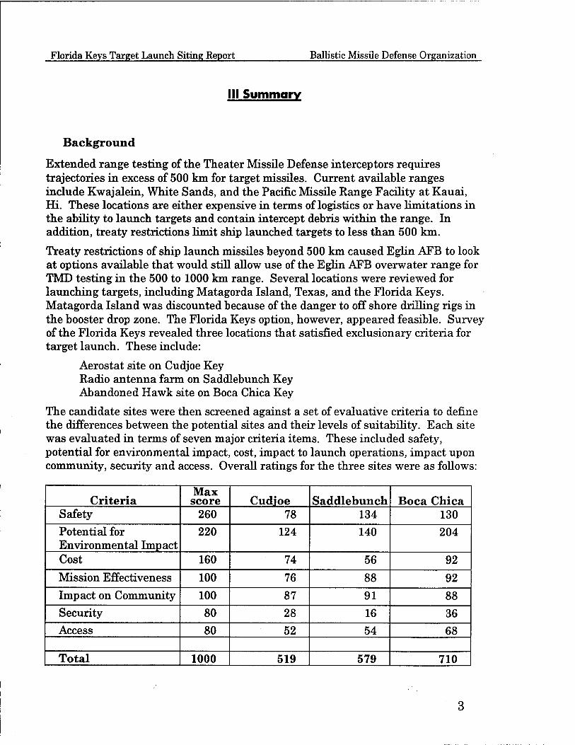
The candidate sites were then screened against a set of evaluative criteria to define the differences between the potential sites and their levels of suitability. Each site was evaluated in terms of seven major criteria items. These included safety, potential for environmental impact, cost, impact to launch operations, impact upon community, security and access. Overall ratings for the three sites were as follows:
Criteria Max score Cudjoe Saddlebunch Boca Chica
Safety 260 78 134 130 Potential for Environmental Impact
220 124 140 204
Cost 160 74 56 92
Mission Effectiveness 100 76 88 92
Impact on Community 100 87 91 88 Security 80 28 16 36 Access 80 52 54 68
Total 1000 519 579 710
3
Florida Keys Target Launch Siting Report Ballistic Missile Defense Organization
Analysis
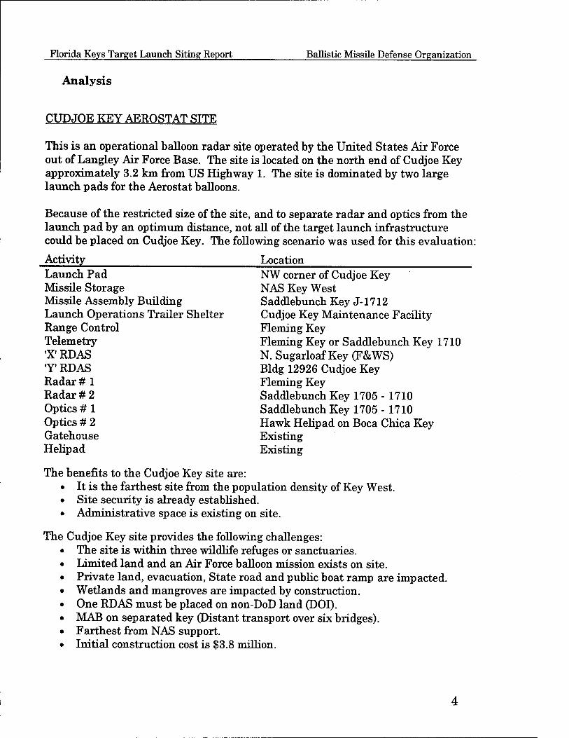
CUD JOE KEY AEROSTAT SITE
This is an operational balloon radar site operated by the United States Air Force out of Langley Air Force Base. The site is located on the north end of Cudjoe Key approximately 3.2 km from US Highway 1. The site is dominated by two large launch pads for the Aerostat balloons.
Because of the restricted size of the site, and to separate radar and optics from the launch pad by an optimum distance, not all of the target launch infrastructure could be placed on Cudjoe Key. The following scenario was used for this evaluation:
Activity Location Launch Pad NW corner of Cudjoe Key Missile Storage NAS Key West Missile Assembly Building Saddlebunch Key J-1712 Launch Operations Trailer Shelter Cudjoe Key Maintenance Facility Range Control Fleming Key Telemetry Fleming Key or S addlebunch Key 1710 *X' RDAS N. Sugarloaf Key (F&WS) •Y' RDAS Bldg 12926 Cudjoe Key Radar # 1 Fleming Key Radar # 2 Saddlebunch Key 1705-1710 Optics # 1 Saddlebunch Key 1705 - 1710 Optics # 2 Hawk Helipad on Boca Chica Key Gatehouse Existing Helipad Existing
The benefits to the Cudjoe Key site are: • It is the farthest site from the population density of Key West. • Site security is already established. • Administrative space is existing on site.
The Cudjoe Key site provides the following challenges: • The site is within three wildlife refuges or sanctuaries. • Limited land and an Air Force balloon mission exists on site. • Private land, evacuation, State road and public boat ramp are impacted. • Wetlands and mangroves are impacted by construction. • One RDAS must be placed on non-DoD land (DOI). • MAB on separated key (Distant transport over six bridges). • Farthest from NAS support. • Initial construction cost is $3.8 million.

Florida Keys Target Launch Siting Report Ballistic Missile Defense Organization
-. •VRDAS -*=—
Launch Operations £=> Trailer --
, - £=£ • *"***
Boca Chica Key
feste Storage
Airport
Bate in KloiTMlan
Range Control Radar §1 Telemetry
Cudjoe Key Aerostat Site Launch Infrastructure Set
A launch pad could be constructed in wetlands northwest of the maintenance area of the Cudjoe Key Air Force Site. The launch shelter and "Y" RDAS could be accommodated on site, however there is minimal clearance for the existing mission and other launch activities. The "X" RDAS was planned on Federal Department of the Interior (DOI) land on Sugarloaf Key. The missile assembly building could be placed on an abandoned antenna site on the Saddlebunch Naval Communications site along with the second radar and optics site. Another optics site is placed at the Hawk site on Boca Chica. Missile storage is on the Naval Air Station. Range control and radar # 1 are located on Fleming Key. Refer to Annex A for detailed site layout drawings.
Florida Keys Target Launch Siting Report Ballistic Missile Defense Organization
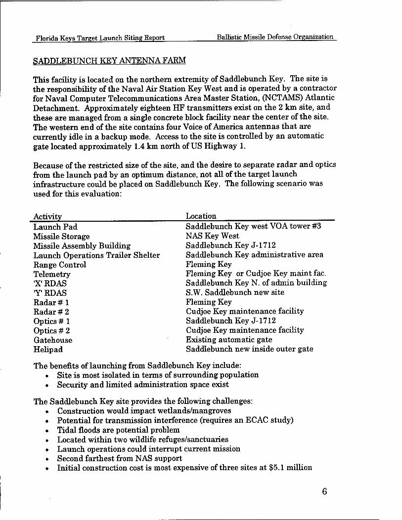
SADDLEBUNCH KEY ANTENNA FARM
This facility is located on the northern extremity of Saddlebunch Key. The site is the responsibility of the Naval Air Station Key West and is operated by a contractor for Naval Computer Telecommunications Area Master Station, (NCTAMS) Atlantic Detachment. Approximately eighteen HF transmitters exist on the 2 km site, and these are managed from a single concrete block facility near the center of the site. The western end of the site contains four Voice of America antennas that are currently idle in a backup mode. Access to the site is controlled by an automatic gate located approximately 1.4 km north of US Highway 1.
Because of the restricted size of the site, and the desire to separate radar and optics from the launch pad by an optimum distance, not all of the target launch infrastructure could be placed on Saddlebunch Key. The following scenario was used for this evaluation:
Activity Location Launch Pad Saddlebunch Key west VOA tower #3 Missile Storage NAS Key West Missile Assembly Building Saddlebunch Key J-1712 Launch Operations Trailer Shelter Saddlebunch Key administrative area Range Control Fleming Key Telemetry Fleming Key or Cudjoe Key maint fac. 'X' RDAS Saddlebunch Key N. of admin building 'Y* RDAS S.W. Saddlebunch new site Radar # 1 Fleming Key Radar # 2 Cudjoe Key maintenance facility Optics # 1 Saddlebunch Key J-1712 Optics # 2 Cudjoe Key maintenance facility Gatehouse Existing automatic gate Helipad Saddlebunch new inside outer gate
The benefits of launching from Saddlebunch Key include: • Site is most isolated in terms of surrounding population • Security and limited a(lministration space exist
The Saddlebunch Key site provides the following challenges: • Construction would impact wetlands/mangroves • Potential for transmission interference (requires an ECAC study) • Tidal floods are potential problem • Located within two wildlife refuges/sanctuaries • Launch operations could interrupt current mission • Second farthest from NAS support • Initial construction cost is most expensive of three sites at $5.1 million
Florida Keys Target Launch Siting Report Ballistic Missile Defense Organization
RadafU2a—=tfi Optics »2
Boca Chica Key
Missile Storage
KtyWMt International Airport
1 0 1 UHU Bcal* in Kkmetera
Range Control Radar »1 Telemetry
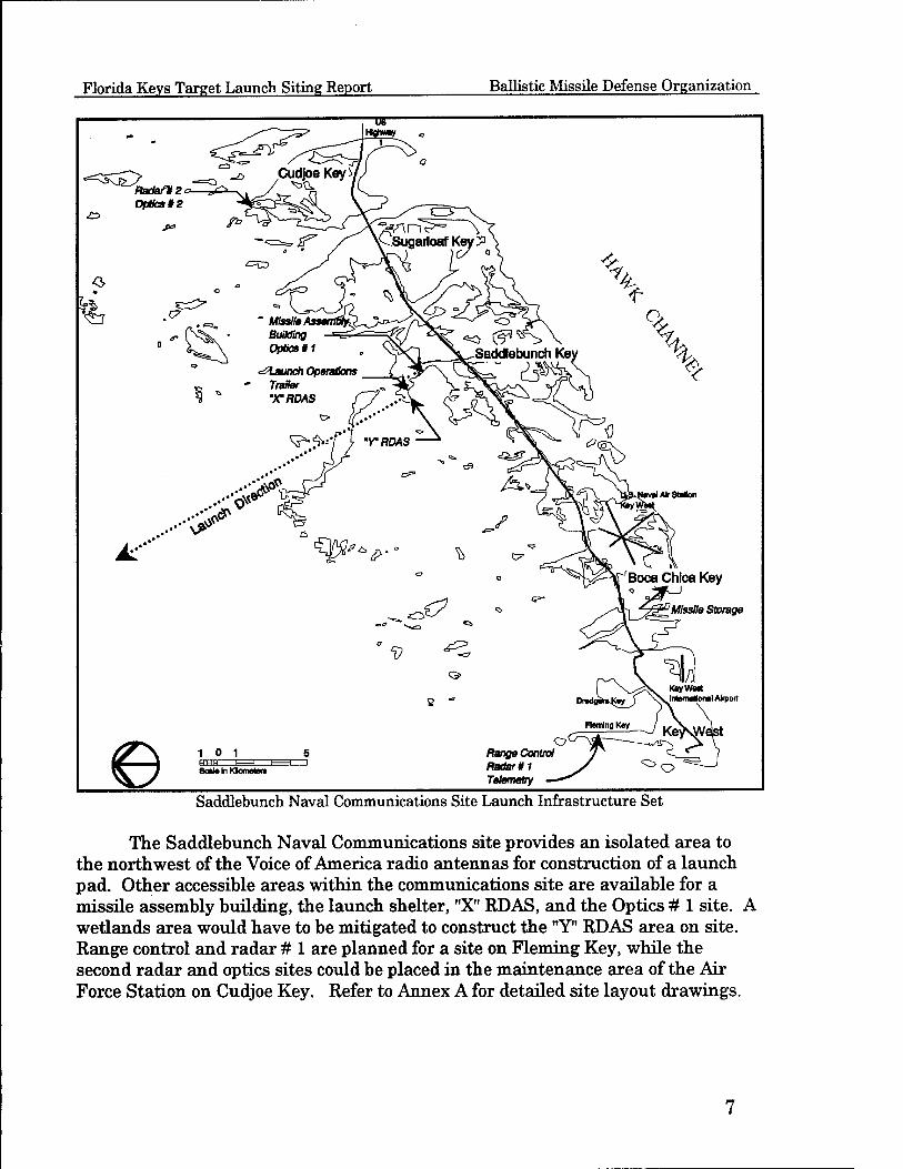
Saddlebunch Naval Communications Site Launch Infrastructure Set
The Saddlebunch Naval Communications site provides an isolated area to the northwest of the Voice of America radio antennas for construction of a launch pad. Other accessible areas within the communications site are available for a missile assembly building, the launch shelter, "X" RDAS, and the Optics # 1 site, wetlands area would have to be mitigated to construct the "Y" RDAS area on site. Range control and radar # 1 are planned for a site on Fleming Key, while the second radar and optics sites could be placed in the maintenance area of the Air Force Station on Cudjoe Key. Refer to Annex A for detailed site layout drawings.

Florida Keys Target Launch Siting Report Ballistic Missile Defense Organization
BOCA CHICA KEY ABANDONED HAWK SITE
Originally built as an air defense site, the facility is located on Naval Air Station Key West property, approximately 1.5 km north of US Highway 1. It lies adjacent to an empty munitions storage area and an area presently used as a small arms range. The site is abandoned, but is fenced and access is controlled through the Naval Air Station. Infrastructure on the site includes roads, six revetted firing pads, six control/observation platforms, two administration buildings in poor condition and two vehicle maintenance parking facilities.
Because of the restricted size of the site, and the desire to separate radar and optics from the launch pad by an optimum distance, not all of the target launch infrastructure could be placed on Boca Chica Key. The following scenario was used for this evaluation:
Activity Location Launch Pad Boca Chica N.E. corner of Hawk site Missile Storage NAS Key West Missile Assembly Building Boca Chica outside inner gate Launch Operations Trailer Shelter Boca Chica S.W. corner of Hawk site Range Control Fleming Key Telemetry Fleming Key or Saddlebunch Key 1710 *X' RDAS Boca Chica Rt. 1 NAS turnout •Y' RDAS Dredgers Key east side Radar # 1 Fleming Key Radar # 2 Saddlebunch Key J-1712 Optics # 1 Dredgers Key east side Optics #2 Saddlebunch Key J-1712 Gatehouse Boca Chica new at outer gate Helipad Boca Chica Hawk site Existing
There are benefits to utilizing the Boca Chica Hawk faculties. These include: • Closest to NAS support • Security is established and supportable from NAS • Limited infrastructure is available.
The Boca Chica Key site provides the following challenges: • Closest to Key West and Highway 1 • Located within one wildlife refuge • An environmental baseline study is required • Some nearby DoD property is currently leased to public • A Proposed weather radar could impact site • Initial cost is $2.4 million
8
Florida Keys Target Launch Siting Report Ballistic Missile Defense Organization
'^'^^ß^ „
*-^
Boca Chica Key
Missile Storage
Kay wot International Altport
Seal* In Ktamaton
Range Control Radar »1 Telemetry
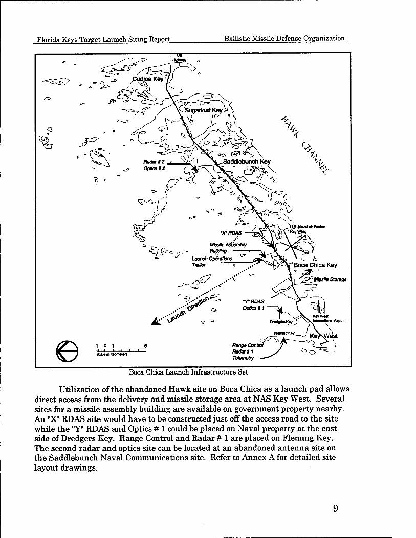
Boca Chica Launch Infrastructure Set
Utilization of the abandoned Hawk site on Boca Chica as a launch pad allows direct access from the delivery and missile storage area at NAS Key West. Several sites for a missile assembly building are available on government property nearby. An "X" RDAS site would have to be constructed just off the access road to the site while the "Y" RDAS and Optics # 1 could be placed on Naval property at the east side of Dredgers Key. Range Control and Radar # 1 are placed on Fleming Key. The second radar and optics site can be located at an abandoned antenna site on the Saddlebunch Naval Communications site. Refer to Annex A for detailed site layout drawings.
9

Florida Keys Target Launch Siting Report Ballistic Missile Defense Organization
Recommendation
Of the three sites studied, the Boca Chica site offers the best technical conditions at the least cost ($2.4 million), for target launch operations including adequate access, site control and real estate for launch infrastructure. RDAS sites would be located behind the launch site just off of highway 1 and another established on Navy property on the eastern end of Dredgers Key. Control radars would be located at sites on Fleming Key and at an abandoned antenna site on Saddlebunch Key. Optics instruments would be positioned at Fleming Key and a second near the helipad at the Hawk site. Range control would share the Fleming Key site, while missile storage could be provided adjacent to the launch site in existing munitions igloos. Area for a Missile Assembly Building is available just outside the fenced area of the old Hawk site along the access road and outside the 381 m (1250 ft.) Quantity Distance Zone.
The Saddlebunch Key site is considered an acceptable second choice. It is the most isolated site from a safety standpoint, but due to elevation, marshland and numerous mangroves, construction would have a much greater affect upon the environment and is the most expensive of the three sites ($5.1 million). In addition, missiles launched from this location will overfly more unpopulated islands (Snipe Keys) within the Great White Heron National Wildlife Refuge. Finally, the location is collocated with a radio antenna field. It is unknown if there is a significant impact to either the radio transmission operation or missile launch operations caused by radio frequency interference. Prior to choosing the Saddlebunch site for missile launch operations, it is recommended that an ECAC study be accomplished to analyze transmission interference from either mission.
Limited area on Cudjoe Key is the driving factor in ranking the existing Aerostat balloon site as third choice. The site is relatively isolated from the public, however, the presence of the Air Force mission greatly restricts the utility of the site for missile launches. Although construction cost ranked second at $3.8 million, operations would have to be split between Cudjoe, Saddlebunch, and Sugarloaf Keys because there is insufficient area on the site to maintain proper quantity distance between the launch pad and the Missile Assembly Building. To obtain proper separation of the launch pad to the Aerostat site construction would have to be accomplished in wetlands areas. The site survey placed the Missile Assembly Building on Saddlebunch Key which would be difficult from an operational standpoint. Obtaining additional land from DOI on Cudjoe Key for construction of a Missile Assembly Building is feasible but uncertain. In addition, obtaining non- DOD land is outside the criteria of this study and therefore, such an option was given a low rating by the siting team. Finally, the proximity of private and public land increased the potential for environmental impacts, and site is farthest from NAS support and missile storage facilities.
10

Florida Keys Target Launch Siting Report Ballistic Missile Defense Organization
There are a number of risks involved with any of the Keys sites and especially with the Boca Chica site. To insure these risks are adequately assessed, it is recommended that the following further actions be undertaken in conjunction with the selection of a launch site in the Florida Keys:
1. Produce an ECAC analysis of the antenna field on Saddlebunch Key to determine the effects upon launch operations.
2. Conduct an environmental baseline study of the Boca Chica Hawk site to determine the extent, if any, of any contamination.
3. Calculate launch trajectory information for each site and use these trajectories to conduct a Launch Hazard Safety study for each site to verify the assumptions used in performing this siting study.
4. Coordinate Airspace and Maritime corridor issues for the area. 5. Develop interservice agreements between BMDO/Air Force/Army and Navy
for required support and responsibilities in conducting launch operations. 6. Develop Memorandums of Agreement with Voice of America, NOAA and the
Federal Department of the Interior (DOI) Service.
11
Florida Keys Target Launch Siting Report Ballistic Missile Defense Organization
IV Requirement
Criteria
The following items were identified as Theater Missile Defense target launch requirements, and were used in selecting alternative sites for evaluation:
1. Theater Missile Defense Engineering, Manufacturing and Development Testing requires high altitude, long and medium range intercepts. Mid range flights are characterized as a distance of between 500 - 1000 km.
2. Current plans envision utilizing the HERA target for TMD mid range intercept testing.
3. Testing of TMD mid-range intercepts is scheduled for FY 96/97.
4. Safety is a major consideration, therefore all intercept debris must remain within the boundaries of the test range.
5. Launch infrastructure will include: A launch pad, Launch Operations Trailer shelter, Range Control Pad, two radar pads, two optics sites, two Real Time Data Acquisition System (RDAS) sites, A missile Assembly building, and a helicopter landing area.
Schedule
Development of the Theater Missile Defense System continues in FY 95 with the first firings of the HERA target followed by initial testing of the THAAD missile at White Sands Missile Range. Testing will continue through FY 95 including short range intercepts by the THAAD and PAC-3. Medium range requirements start in mid FY 96 and continue through FY 97. The need for a medium range area are acute in FY 97 and are expected to continue on past PAC-3 and THAAD deployment. Navy TMD testing within the same period may also require land based target launch to acceptable range areas. Once Theater Missile Defense systems have been deployed/fielded, there are yet undefined requirements for periodic proficiency and certification testing. These firings will likely require the use of mid or long range testing facilities.
12
Florida Keys Target Launch Siting Report Ballistic Missile Defense Organization
V Alternatives
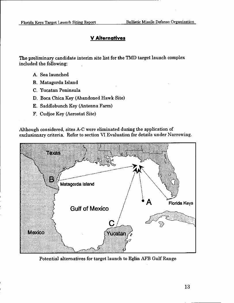
The preliminary candidate interim site list for the TMD target launch complex included the following:
A. Sea launched
B. Matagorda Island
C. Yucatan Peninsula
D. Boca Chica Key (Abandoned Hawk Site)
E. Saddlebunch Key (Antenna Farm)
F. Cudjoe Key (Aerostat Site)
Although considered, sites A-C were eliminated during the application of exclusionary criteria. Refer to section VI Evaluation for details under Narrowing.
Mexico
Potential alternatives for target launch to Eglin AFB Gulf Range
13

Florida Keys Target Launch Siting Report Ballistic Missile Defense Organization
VI Evaluation
Assumptions
The following assumptions were used as a basis for evaluating all of the candidate sites:
1. Mid range testing at Eglin AFB would not be required until FY 97.
2. Environmental assessment beyond the Extended Test Range Environmental Impact Statement would be required to utilized any selected alternatives at Eglin AFB, other than the sea based target launch.
3. Ground Launch Hazard Area for the HERA missile would be similar to that calculated for Wake Island (i.e. 1500 m radius). Annex B contains the launch hazard data used as a basis for establishing the Launch Hazard Area for the HERA missile. This LHA is more conservative than that used for other TMD target requirements.
4. Naval Air Station, Key West will provide as much personnel and community support facilities as possible.
5. Base Realignment and Closure (BRAC) 95 does not impact target launch site
Narrowing
The following Exclusionary Criteria was applied to all of the candidate sites for the purpose of site narrowing:
Criteria Rationale Test Range must provide sufficient area to satisfy EMD test requirements.
EMD testing for TMD requires high altitude, Mid and Long range intercepts.
Interceptor, Radar and Target launch sites must be land based
Sea launched interceptors and targets present technical challenges outside the scope of this effort (BMDO directive). In addition, Intermediate Range Nuclear Forces treaty considerations require targets with ranges between 500 km and 5000 km to be launched from designated fixed land sites.
14

Florida Keys Target Launch Siting Report Ballistic Missile Defense Organization
Criteria Rationale Debris from interceptor or target must not impact populated areas
Given the desire for testing to include high altitude intercepts, debris footprints become large and could result in impacting populated areas.
Test range must be available for EMD tests starting in FY 97.
Testing of THAAD interceptors is scheduled for FY 97.
Target launch site must be a minimum of 150' x 150'.
Site must have necessary space to support all HERA ground support equipment.
Test range must have enough area for support buildings.
Testing support personnel and equipment require maintenance, defueling, administrative areas and storage areas.
Air Space corridors to Eglin intercept point obtainable
Must be allowed to launch target toward Eglin range.
Launch site within mid-range intercept distance criteria (500-1000 km)
Must meet Theater Mid-Range Scenario criteria.
Azimuth Vectors from Eglin Range intercept location to launch site must be between 300 degrees and 340 degrees.
Must maintain intercept debris pattern within Eglin Test range.
Launch site must be within U.S. controlled territory.
Eliminate treaty and country-to- country legal disputes.
DoD controlled real estate with a radius of 1500 m. around the launch platform.
Minimum acceptable launch hazard area for safety and mission risk. Refer to Annex B for basis of HERA LHA.
Booster Drop Zone must be capable of being fully evacuated at time of launch. The drop zone must be 20 x 20 km and between 80 - 130 km from launch.
Safety/Security. Note, the second stage booster will follow into the EWTA after separation.
Real estate requirements to support facilities to include a missile assembly building (1 bay) with a 381 m inhabited building quantity distance zone (QD), and launch pad with a 381 m QD zone.
Sufficient land area to site mission facilities and contain adequate safety zones must be available to support mission.
15
Florida Keys Target Launch Siting Report Ballistic Missile Defense Organization
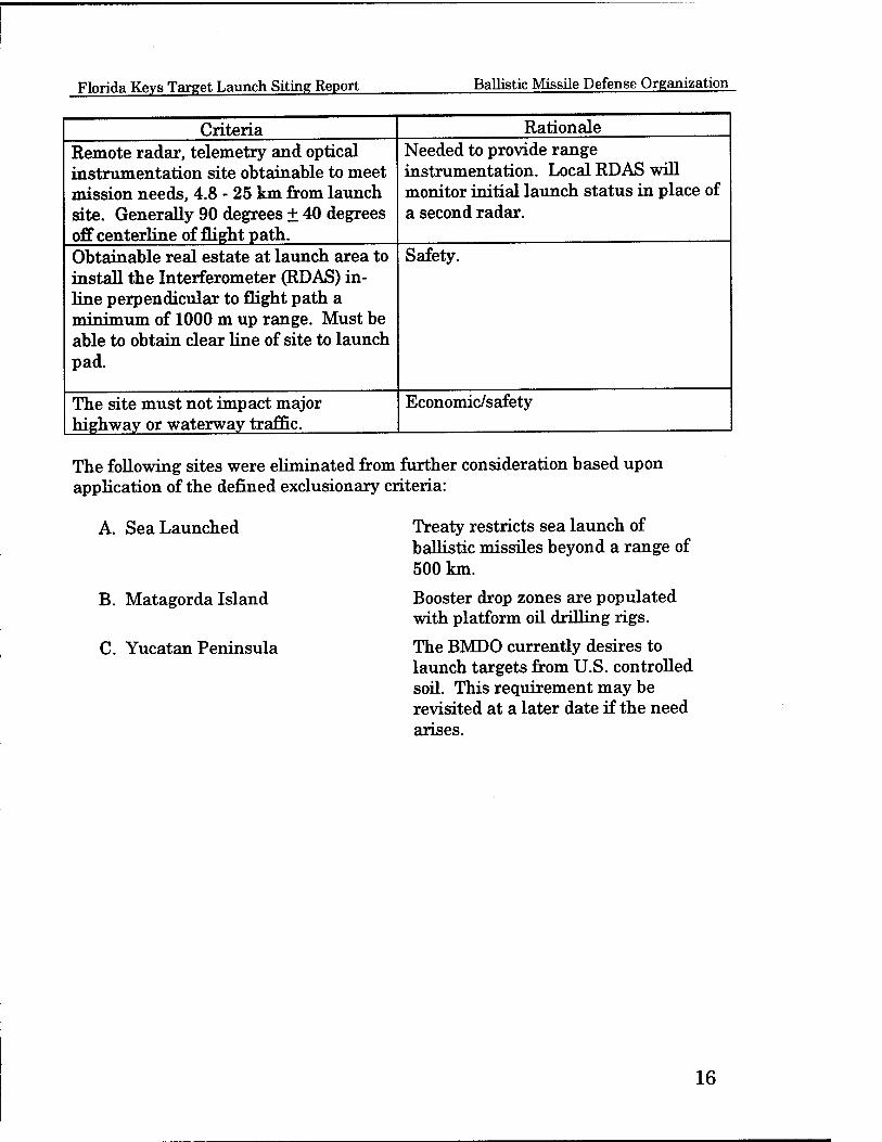
Criteria Remote radar, telemetry and optical instrumentation site obtainable to meet mission needs, 4.8 - 25 km from launch site. Generally 90 degrees + 40 degrees off centerline of flight path. Obtainable real estate at launch area to install the Interferometer (RDAS) in- line perpendicular to flight path a minimum of 1000 m up range. Must be able to obtain clear line of site to launch pad.
The site must not impact major highway or waterway traffic.
Rationale Needed to provide range instrumentation. Local RDAS will monitor initial launch status in place of a second radar.
Safety.
Economic/safety
The following sites were eliminated from further consideration based upon application of the defined exclusionary criteria:
A. Sea Launched
B. Matagorda Island
C. Yucatan Peninsula
Treaty restricts sea launch of ballistic missiles beyond a range of 500 km.
Booster drop zones are populated with platform oil drilling rigs.
The BMDO currently desires to launch targets from U.S. controlled soil. This requirement may be revisited at a later date if the need arises.
16
Florida Keys Target Launch Siting Report Ballistic Missile Defense Organization
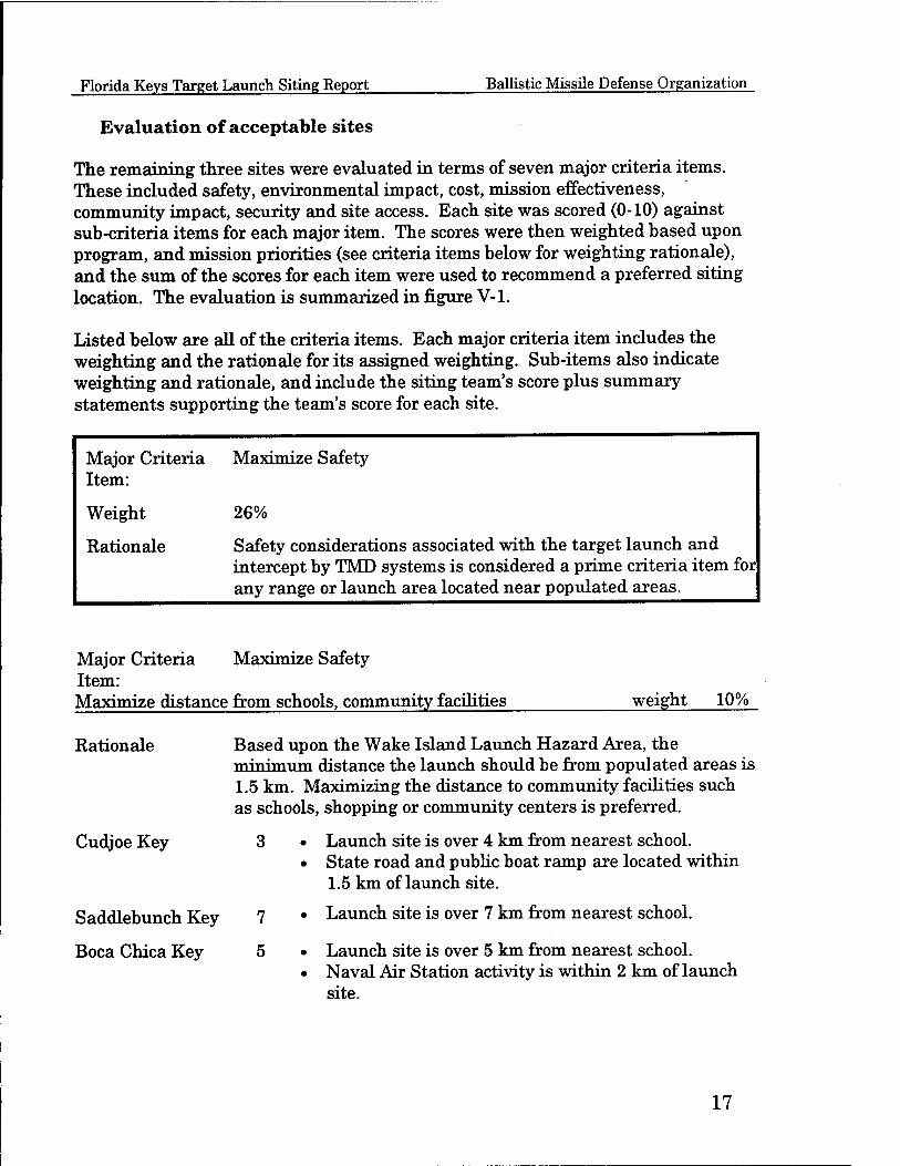
Evaluation of acceptable sites
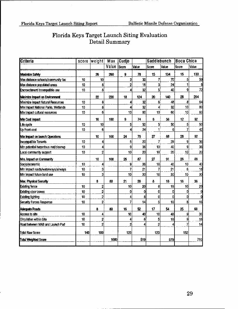
The remaining three sites were evaluated in terms of seven major criteria items. These included safety, environmental impact, cost, mission effectiveness, community impact, security and site access. Each site was scored (0-10) against sub-criteria items for each major item. The scores were then weighted based upon program, and mission priorities (see criteria items below for weighting rationale), and the sum of the scores for each item were used to recommend a preferred siting location. The evaluation is summarized in figure V-l.
Listed below are all of the criteria items. Each major criteria item includes the weighting and the rationale for its assigned weighting. Sub-items also indicate weighting and rationale, and include the siting team's score plus summary statements supporting the team's score for each site.
Major Criteria Item:
Weight
Rationale
Maximize Safety
26%
Safety considerations associated with the target launch and intercept by TMD systems is considered a prime criteria item for any range or launch area located near populated areas.
Major Criteria Maximize Safety Item: Maximize distance from schools, community facilities weight 10%
Rationale
Cudjoe Key
Saddlebunch Key
Boca Chica Key
Based upon the Wake Island Launch Hazard Area, the minimum distance the launch should be from populated areas is 1.5 km. Maximizing the distance to community facilities such as schools, shopping or community centers is preferred.
3 • Launch site is over 4 km from nearest school. • State road and public boat ramp are located within
1.5 km of launch site.
7 • Launch site is over 7 km from nearest school.
5 • Launch site is over 5 km from nearest school. • Naval Air Station activity is within 2 km of launch
site.
17
Florida Keys Target Launch Siting Report Ballistic Missile Defense Organization
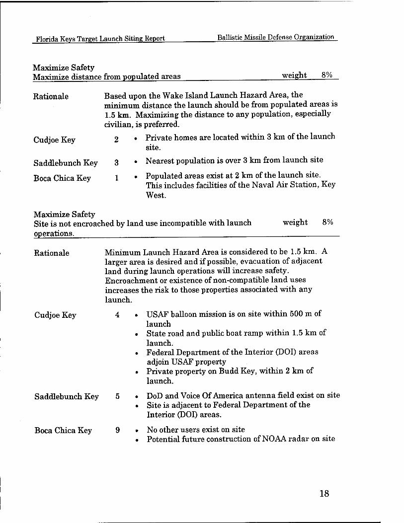
Maximize Safety Maximize distance from populated areas weight 8%
Rationale
Cudjoe Key
Saddlebunch Key
Boca Chica Key
Based upon the Wake Island Launch Hazard Area, the rninimum distance the launch should be from populated areas is 1.5 km. Maximizing the distance to any population, especially civilian, is preferred.
2 • Private homes are located within 3 km of the launch site.
3 • Nearest population is over 3 km from launch site
1 • Populated areas exist at 2 km of the launch site. This includes facilities of the Naval Air Station, Key West.
Maximize Safety Site is not encroached by land use incompatible with launch operations.
weight 8%
Rationale
Cudjoe Key
Saddlebunch Key
Boca Chica Key
Minimum Launch Hazard Area is considered to be 1.5 km. A larger area is desired and if possible, evacuation of adjacent land during launch operations will increase safety. Encroachment or existence of non-compatible land uses increases the risk to those properties associated with any launch.
USAF balloon mission is on site within 500 m of launch State road and public boat ramp within 1.5 km of launch. Federal Department of the Interior (DOI) areas adjoin USAF property Private property on Budd Key, within 2 km of launch.
DoD and Voice Of America antenna field exist on site Site is adjacent to Federal Department of the Interior (DOI) areas.
No other users exist on site Potential future construction of NOAA radar on site
18

Florida Keys Target Launch Siting Report Ballistic Missile Defense Organization
Major Criteria Item:
Weight
Rationale
Minimize impact on Environment
22%
Major opposition to range operations have arisen as a result of environmental considerations. Consideration of the environmental impact upfront can alleviate the situation and help identify avenues that allow programs to continue.
Minimize impact on Environment Minimize impact to natural resources weight 8%
Rationale
Cudjoe Key
Comparing the number of natural resources that may be impacted by launch operations allows the decision maker to weigh the consequences of various alternatives.
Impacts the National Key Deer Refuge Impacts the National White Heron Refuge Located within the Marine Sanctuary
Saddlebunch Key 6
Boca Chica Key 8
Impacts the National White Heron Refuge Located within the Marine Sanctuary
Located within the Marine Sanctuary Less overflight of the National White Heron Refuge
Minimize impact on Environment Minimize impact to National Monument, wetlands or State Parks weight 8%
Rationale
Cudjoe Key
Saddlebunch Key
Existence of national monuments, or state parks can severely restrict activity at any selected site. Presence of wetlands has a significant impact on construction or the ability to construct required infrastructure.
Launch pad placed on wetlands area Access road to pad must cross open channel No National Monuments or State Parks involved
Launch pad located on low, potential wetland area RDAS location remote in wetlands Access to RDAS site must transit wetland area No National Monuments or State Parks involved
Boca Chica Key 10 No wetlands involved in construction No National Monuments or State Parks involved
19

Florida Keys Target Launch Siting Report Ballistic Missile Defense Organization
Minimize Impact on Environment Minimize impact to known cultural resources (archeological and historical)
weight 6%
Rationale Impact to archeological sites and historically significant struc- tures can delay or prohibit development of programs and concomitant infrastructure. Early identification of potential cultural resources help decision makers avoid problems.
Cudjoe Key 10
Saddlebunch Key 10
Boca Chica Key 9
No known cultural resources
No known cultural resources
Site is alternate candidate for National Historic Site.
Major Criteria Item:
Weight
Rationale
Minimize Cost
16%
Site should minimize impact on program cost and effectiveness. Reduced cost, both initial and life cycle, will maximize funding available for additional mission testing.
■Minimize Cost Site should minimize Life Cycle cost over ten year occupancy. weight 10%
Rationale
Cudjoe Key
Saddlebunch Key
Boca Chica Key
The cost of doing business is a long term problem. Often the long term cost outweighs the initial investment in a site. Consideration of the life cycle cost associated with each site will provide the decision maker with a better appreciation of the overall cost of a site to the program.
5 • Economic Analysis assumed same cost at all sites • Requires 42 km round trip for NAS support • Minimal maintenance required over ten years since
new facilities are being provided
5 • Economic Analysis assumed same cost at all sites • Requires 22 km round trip for NAS support • Minimal maintenance required over ten years since
new facilities are being provided
5 • Economic Analysis assumed same cost at all sites • Commuting distance is minimized
20

Florida Keys Target Launch Siting Report Ballistic Missile Defense Organization
Minimize Cost Site should minimize "Up Front" cost through use of existing facilities and ease of construction. .
weight 6%
Rationale
Cudjoe Key
Saddlebunch Key
Boca Chica Key
Cost of getting on the site and beginning operations can be significantly impacted by the available budget. limited test and evaluation funding demands prudent and cost effective investment of resources. Scoring based upon less than $500K as best and over $5.5 million as worst case.
4 • $3.8 million in construction cost • Construction will be split between Cudjoe and
Saddlebunch key (MÄB) • Construction on unknown, virgin wetland has risk • Utilities are nearby • Minimal use of existing facilities increase "up front"
cost.
1 • $5.1 million in construction cost • Construction on wetland has risk. • Presence of antennas complicate construction. • Minimal use of existing facilities increase "up front"
cost.
7 • $2.4 million in construction cost • Construction is split between Fleming, Dredgers and
Boca Chica Keys • Site is near contractor support.
Major Criteria Item:
Weight
Rationale
Maximize Mission Effectiveness
10%
The ability of the location to support launch operations is critical to the success of the mission. The site should be unencumbered by other tenants, it should have no inherent environmental hazards that would affect operations and the local economy should be able to easily support the launch mission crew.
21

Florida Keys Target Launch Siting Report Ballistic Missile Defense Organization
Maximize Mission Effectiveness Incompatible tenants exist on site weight 4%
Rationale
Cudjoe Key
Saddlebunch Key
Boca Chica Key
A significant factor in mission effectiveness is the impact of other installation missions on launch operations. Included in this evaluation was the displacement of existing installation missions or resources required to execute missions. The best situation would be to have no other tenants, and to have no impact on any other mission area.
Air Force Aerostat mission exists on site State road and Public boat ramp nearby Host unit will be excluded from site during launch Budd Key private residences require evacuation
Navy operated antenna site mission exists Host unit will be excluded from site during launch Voice of America transmission antennas are backup, but exist on site
No other tenants on immediate property Potential exists for weather radar to be built on site Navy Flying operation is located within 3 km
Maximize Mission Effectiveness Minimize potential for hazardous material or potential hazardous clean up at site.
weight 4%
Rationale
Cudjoe Key
Saddlebunch Key
Boca Chica Key
Cost and mission effectiveness may be impacted by hazards that exist on the site. Areas requiring clean-up may not be available for construction and or use.
7 • Building 926 is a paint storage facility • LOT site is a vehicle maintenance facility with
potential fuel contamination. None noticed, however.
7 • None observed • Possible HF hazard to mission operations
6 • Requires baseline study prior to use • Large quantity of old buildings and materials • Potential for some lead based paint, POL and PCB
cleanup required
22

Florida Keys Target Launch Siting Report
Maximize Mission Effectiveness Local community able to support TDY personnel (100 persons)
Ballistic Missile Defense Organization
weight 2%
Rationale
Cudjoe Key
Up to 100 personnel will be required during a sixty day period to build up, support and launch the HERA target. The local community around the site must be able to support these personnel.
10
Saddlebunch Key 10
Boca Chica Key 10
Site is 34 km from Key West Site is 21 km from NAS, Key West support
Site is 24 km from Key West Site is 13 km from NAS, Key West support
Site is 13 km from Key West Site is 2 km from NAS, Key West support
Major Criteria Item:
Weight
Rationale
Minimize Impact on Community
10%
Depending upon the location of the launch site, launch operations can have a significant impact to the socio/economic resources of a community, the operation at local airports, railways and highways, and upon future land development.
Minimize Impact on Community Minimize impact on socio/economic resources to include infrastructure
weight 4%
Rationale
Cudjoe Key
Saddlebunch Key
Boca Chica Key
Launch operations can affect existing socio/economic assets and enterprises within a community. Selection of a site should avoid negative impacts to these activities.
9 • Fish camp on nearby island would have to be evacuated.
• State road and public boat ramp would be impacted.
• No impacts to local infrastructure. 10
10 Government offices nearest structures to launch area.
No impacts to community infrastructure
23

Florida Keys Target Launch Siting Report Ballistic Missile Defense Organization
Minimize Impact on Community Minimize impact on local roadways, waterways and aircraft weight 3% approach/departure to airfields.
Rationale
Cudjoe Key
Saddlebunch Key
Boca Chica Key
Launch operations may shut down or limit traffic on transportation systems that are vital to a community. Site selection should try to avoid interruptions to community transportation systems..
7 • Air traffic corridor is nearby • Highway 1 impacted by missile transfer from MAB
to launch pad.
7 • Air traffic corridor is nearby. • One waterway would be closed during launch.
6 • Very close to NAS flight pattern • Air traffic corridor is nearby. • One or more waterways require closure during
launch. • Closest launch site to Highway 1.
Minimize Impact on Community Minimize Impact future land use weight 3%
Rationale Ideal site will not affect future land use. Worst case is encroachment by adjacent development that would degrade safety of operations in the future, or prevent future use of launch site.
Cudjoe Key 10
Saddlebunch Key 10
Boca Chica Key 10
Fish camp located within flight path. Private land on Budd Key is currently undeveloped. Most of site is surrounded by water and wetlands
owned by the Federal Department of the Interior .
No nearby adjacent development exists. Surrounded by water and wetlands owned by the
Federal Department of the Interior.
No adjacent private land. Some adjacent government land has been leased to private industry.
24
Florida Keys Target Launch Siting Report Ballistic Missile Defense Organization
Major Criteria Item:
Maximize Physical Security
Weight 8%
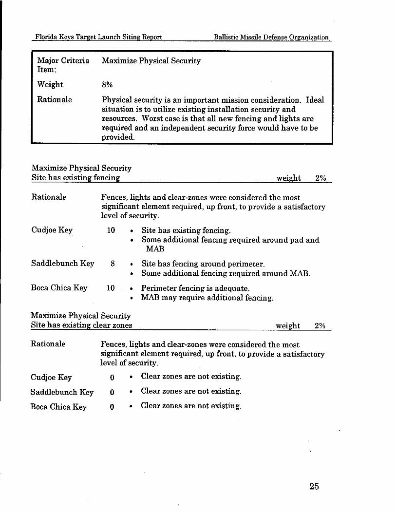
Rationale Physical security is an important mission consideration. Ideal situation is to utilize existing installation security and resources. Worst case is that all new fencing and lights are required and an independent security force would have to be provided.
Maximize Physical Security Site has existing fencing weight 2%
Rationale
Cudjoe Key
Saddlebunch Key
Boca Chica Key
Fences, lights and clear-zones were considered the most significant element required, up front, to provide a satisfactory level of security.
10
8
10
Site has existing fencing. Some additional fencing required around pad and
MAB
Site has fencing around perimeter. Some additional fencing required around MAB.
Perimeter fencing is adequate. MAB may require additional fencing.
Maximize Physical Security Site has existing clear zones weight 2%
Rationale
Cudjoe Key
Saddlebunch Key
Boca Chica Key
Fences, lights and clear-zones were considered the most significant element required, up front, to provide a satisfactory level of security.
• Clear zones are not existing. 0
0
0
Clear zones are not existing.
Clear zones are not existing.
25
Florida Keys Target Launch Siting Report Ballistic Missile Defense Organization
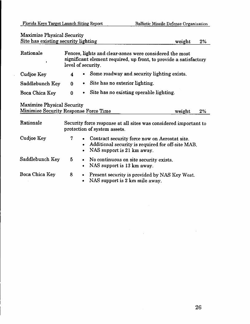
Maximize Physical Security Site has existing security lighting weight 2%
Rationale
Cudjoe Key
Saddlebunch Key
Boca Chica Key
Fences, lights and clear-zones were considered the most significant element required, up front, to provide a satisfactory level of security.
4 • Some roadway and security lighting exists.
0 • Site has no exterior lighting.
0 • Site has no existing operable lighting.
Maximize Physical Security Minimize Security Response Force Time weight 2%
Rationale
Cudjoe Key
Saddlebunch Key
Boca Chica Key
Security force response at all sites was considered important to protection of system assets.
Contract security force now on Aerostat site. Additional security is required for off-site MAB. NAS support is 21 km away.
No continuous on site security exists. NAS support is 13 km away.
8 Present security is provided by NAS Key West. NAS support is 2 km mile away.
26
Florida Keys Target Launch Siting Report Ballistic Missile Defense Organization
Major Criteria Item:
Weight
Rationale
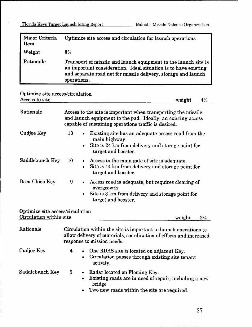
Optimize site access and circulation for launch operations
8%
Transport of missile and launch equipment to the launch site is an important consideration. Ideal situation is to have existing and separate road net for missile delivery, storage and launch operations.
Optimize site access/circulation Access to site weight 4%
Rationale
Cudjoe Key
Access to the site is important when transporting the missile and launch equipment to the pad. Ideally, an existing access capable of sustaining operations traffic is desired.
10
Saddlebunch Key 10
Boca Chica Key
Existing site has an adequate access road from the main highway.
Site is 24 km from delivery and storage point for target and booster.
Access to the main gate of site is adequate. Site is 14 km from delivery and storage point for target and booster.
Access road is adequate, but requires clearing of overgrowth
Site is 3 km from delivery and storage point for target and booster.
Optimize site access/circulation Circulation within site weight 2%
Rationale
Cudjoe Key
Saddlebunch Key
Circulation within the site is important to launch operations to allow delivery of materials, coordination of efforts and increased response to mission needs.
4 • One RDAS site is located on adjacent Key. • Circulation passes through existing site tenant
activity.
5 • Radar located on Fleming Key. • Existing roads are in need of repair, including a new
bridge • Two new roads within the site are required.
27
Florida Keys Target Launch Siting Report Ballistic Missile Defense Organization
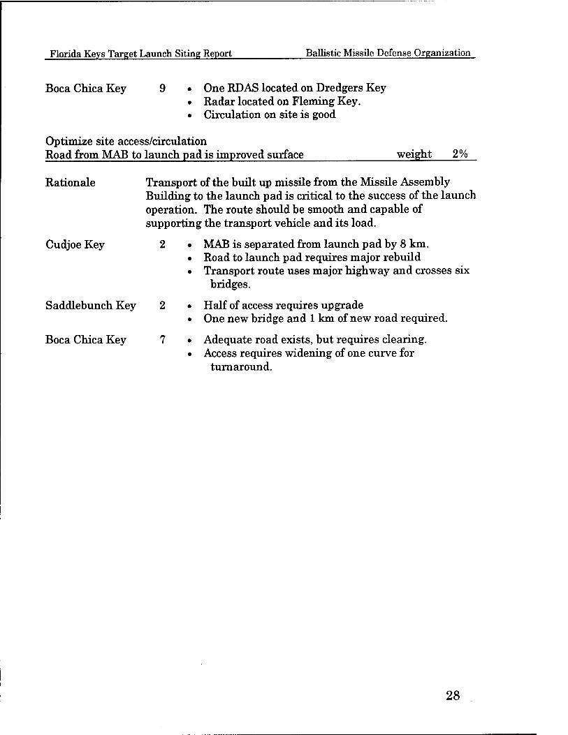
Boca Chica Key One RDAS located on Dredgers Key Radar located on Fleming Key. Circulation on site is good
Optimize site access/circulation Road from MAB to launch pad is improved surface weight 2%
Rationale
Cudjoe Key
Saddlebunch Key
Boca Chica Key
Transport of the built up missile from the Missile Assembly Building to the launch pad is critical to the success of the launch operation. The route should be smooth and capable of supporting the transport vehicle and its load.
2 • MAB is separated from launch pad by 8 km. • Road to launch pad requires major rebuild • Transport route uses major highway and crosses six
bridges.
2 • Half of access requires upgrade • One new bridge and 1 km of new road required.
7 • Adequate road exists, but requires clearing. • Access requires widening of one curve for
turnaround.
28
Florida Keys Target Launch Siting Report Ballistic Missile Defense Organization
Florida Keys Target Launch Siting Evaluation Detail Summary
Criteria score weight Max Cudjo Saddlebunch Boca Chica Value Score Value Score Value Score Value
Maximize Safely 26 260 9 78 15 134 15 130
Max distance schools/community fac 10 10 3 30 7 70 5 50
Max distance populated areas 10 8 2 16 3 24 1 8
Encroachment incompatible use 10 8 4 32 5 40 9 72
Minimize Impact on Environment 22 220 18 124 20 140 28 204
Minimize Impact Natural Resources 10 8 4 32 6 48 8 64
Min Impact National Parks, Wetlands 10 8 4 32 4 32 10 80
Min Impact cultural resources 10 6 10 60 10 60 10 60
Min Cost Impact 16 160 9 74 6 56 12 92
Life cycle 10 10 5 50 5 50 5 50
Up Front cost 10 6 4 24 1 6 7 42
Min Impact on launch Operations 10 100 24 76 27 88 28 92
Incompatible Tenants 10 4 5 20 7 28 9 36
Min potential hazardous mat/cleanup 10 4 9 36 10 40 9 36
Local community support 10 2 10 20 10 20 10 20
Min. Impact on Community 10 100 26 87 27 91 26 88
Socio/economic 10 4 9 36 10 40 10 40
Min Impact roads/waterways/airways 10 3 7 21 7 21 6 18
Min Impact future land use 10 3 10 30 10 30 10 30
Max Physical Security 8 80 21 28 8 16 18 36
Existing fence 10 2 10 20 8 16 10 20
Existing clear zones 10 2 0 0 0 0 0 0
Existing lighting 10 2 4 8 0 0 0 0
Security Forces Response 10 2 7 14 5 10 8 16
Adequate Roads 8 80 16 52 17 54 25 68
Access to site 10 4 10 40 10 40 9 36
Circulation within Site 10 2 4 8 5 10 9 18
Road between MAB and Launch Pad 10 2 2 4 2 4 7 14
Total Raw Score 140 100 123 120 152
Total Weighted Score 1000 519 579 710
29

Florida Keys Target Launch Siting Report Ballistic Missile Defense Organization
Annex A Target Launch Complex Functional Requirements
U.S. Army Corps of Engineers HuntsvilleDivislon
FUNCTIONAL REQUIREMENTS FOR
BMDO PROJECT NO. 372 THEATER MISSILE DEFENSE PAC3 & THAAD TARGET LAUNCH FACILITIES
KEY WEST, FLORIDA
DRAFT JANUARY 1995
PURPOSE
The purpose of this document is to establish the functional requirements to be used in design of the Theater Missile Defense (TMD) Target Launch Facilities, located near Key West, Florida.
CONTENTS
PARTI GENERAL A. FUNCTIONAL DESCRIPTION 1 B. COMPLEX FACILITY SUMMARY 2
PART II SITE AND UTILITY REQUIREMENTS A. SITING APPROVAL 2 B. GENERAL INFORMATION 2 C. SITES TO BE UTILIZED 4
1. CudjoeKey 4 2. Saddlebunch Key 11 3. Boca Chica Key 17
PARTIE FACILITY REQUIREMENTS A. LAUNCH PAD 23
2. Mechanical 24 3. Electrical 24 4. Fire Protection: N/A 25
B. LAUNCH EQUIPMENT BUILDING (LEB) 28 1. Architectural and Structural 28 2. Mechanical 30 3. Electrical 31 4. Fire Protection 32
C. LAUNCH OPERATION TRAILERS SHELTER (LOT) 35 1. Architectural and Structural 35 2. Mechanical 36 3. Electrical 37 4. Fire Protection 38
D. MISSILE ASSEMBLY BUILDING (MAB) 40 1. Architectural and Structural 40 2. Mechanical 42 3. Electrical 43 4. Fire Protection 45
E. ENVIRONMENTAL SHELTER 48 1. Architectural and Structural 48 2. Mechanical 50 3. Electrical 51 4. Fire Protection 51
F. REAL TIME DATA ACQUISITION SYSTEM (RDAS) 53 1. Architectural and Structural 53 2. Mechanical 53 3. Electrical 53
ii

4. Fire Protection 53 G. RADAR SITE 56
1. Architectural and Structural 56 2. Mechanical 56 3. Electrical 56 4. Fire Protection 56
H. OPTICS SITE 58 1. Architectural and Structural 58 2. Mechanical 58 3. Electrical 58 4. Fire Protection 58
I. RANGE CONTROL SITE 60 1. Architectural and Structural 60 2. Mechanical 60 3. Electrical 60 4. Fire Protection 61
J. HELIPAD 63 1. Architectural and Structural 63 2. Mechanical 63 3. Electrical 63 4. Fire Protection 63
K. GUARDHOUSE 63 1. Architectural and Structural 63 2. Mechanical 66 3. Electrical 66 4. Fire Protection 67
TABLES
LAUNCH SITE FACILITY LAYOUT MATPJX 1 LAUNCH PADS MISSION EQUIPMENT 26 LAUNCH EQUIPMENT ROOM MISSION EQUIPMENT 33 MISSILE ASSEMBLY BUILDING MISSION EQUIPMENT 46 RDAS SITES MISSION EQUIPMENT 54 RADAR SITES MISSION EQUIPMENT 57 OPTICS SITE MISSION EQUIPMENT 59 RANGE CONTROL SITE MISSION EQUIPMENT 62
FIGURES
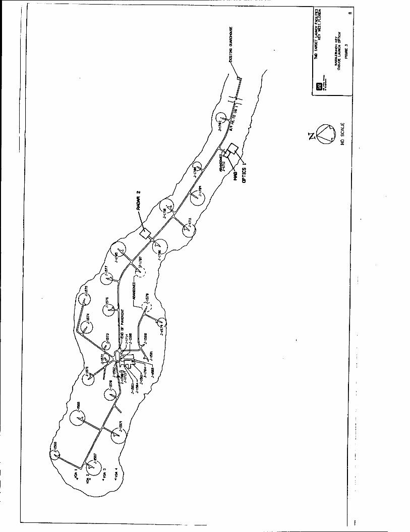
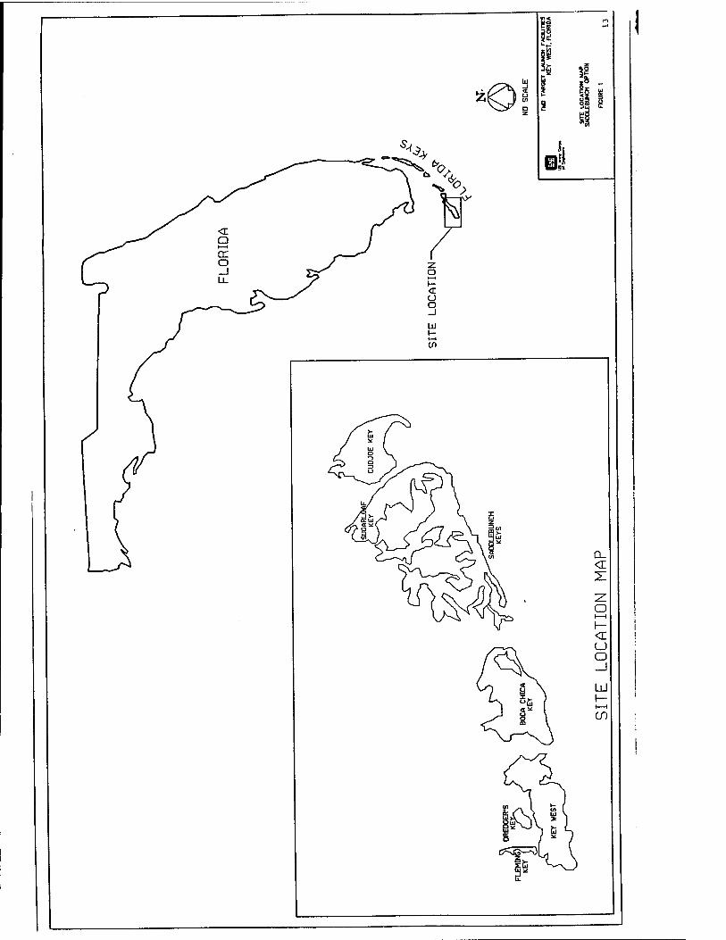
Site Location Map - Cudjoe Option 6 Cudjoe Key - Cudjoe Launch Option 7 Saddlebunch Key - Cudjoe Launch Option 8 Boca Chica Key - Cudjoe Launch Option 9
iii

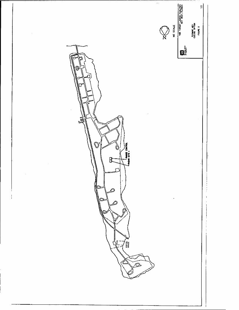
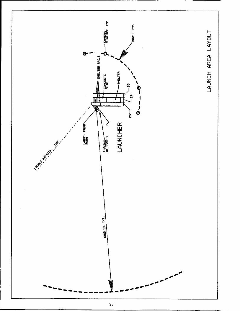
Fleming Key - Cudjoe Launch Option 10 Site Location Map - Saddlebunch Launch Option 13 Saddlebunch Key - Saddlebunch Launch Option 14 Cudjoe Key - Saddlebunch Launch Option 15 Fleming Key - Saddlebunch Launch Option 16 Site Location Map - Boca Chica Option 19 Boca Chica Key- Boca Chica Option 20 Saddlebunch Key - Boca Chica Option 21 Fleming Key - Boca Chica Option 22 Launch Area Layout 27 Launch Equipment Building (LEB) 34 Launch Operation Trailers Shelter (LOT) 39 Missile Assembly Building (MAB) 47 Environmental Shelter 52 RDAS Detail 55 Guardhouse 68
IV
PARTI GENERAL
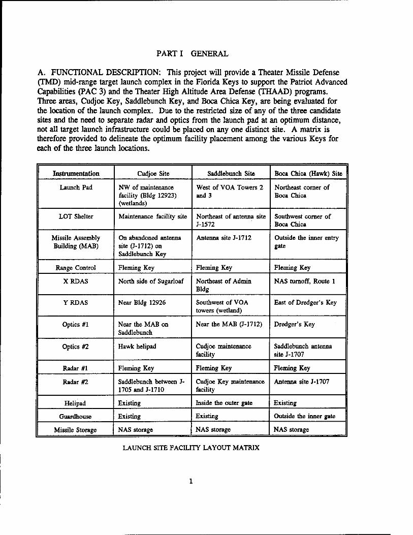
A. FUNCTIONAL DESCRIPTION: This project will provide a Theater Missile Defense (TMD) mid-range target launch complex in the Florida Keys to support the Patriot Advanced Capabilities (PAC 3) and the Theater High Altitude Area Defense (THAAD) programs. Three areas, Cudjoe Key, Saddlebunch Key, and Boca Chica Key, are being evaluated for the location of the launch complex. Due to the restricted size of any of the three candidate sites and the need to separate radar and optics from the launch pad at an optimum distance, not all target launch infrastructure could be placed on any one distinct site. A matrix is therefore provided to delineate the optimum facility placement among the various Keys for each of the three launch locations.
Instrumentation Cudjoe Site Saddlebunch Site Boca Chica (Hawk) Site
Launch Pad NW of maintenance facility (Bldg 12923) (wetlands)
West of VOA Towers 2 and 3
Northeast corner of Boca Chica
LOT Shelter Maintenance facility site Northeast of antenna site J-1572
Southwest corner of Boca Chica
Missile Assembly Building (MAB)
On abandoned antenna site (J-1712) on Saddlebunch Key
Antenna site J-1712 Outside the inner entry gate
Range Control Fleming Key Fleming Key Fleming Key
XRDAS North side of Sugarloaf Northeast of Admin Bldg
NAS turnoff, Route 1
YRDAS Near Bldg 12926 Southwest of VOA towers (wetland)
East of Dredger's Key
Optics #1 Near the MAB on Saddlebunch
Near the MAB (J-1712) Dredger's Key
Optics #2 Hawk helipad Cudjoe maintenance facility
Saddlebunch antenna site J-1707
Radar #1 Fleming Key Fleming Key Fleming Key
Radar Wl Saddlebunch between J- 1705 and J-1710
Cudjoe Key maintenance facility
Antenna site J-1707
Helipad Existing Inside the outer gate Existing
Guardhouse Existing Existing Outside the inner gate
Missile Storage NAS storage NAS storage NAS storage
LAUNCH SITE FACILITY LAYOUT MATRDC

B. COMPLEX FACILITY SUMMARY: The facility and site preparation requirements are common to all three launch complex locations. Each includes a launch pad with a launch equipment building and a retractable environmental shelter; a missile assembly building; a shelter to house seven launch operation trailers, three of which require hardened protection; a site for range control; sites for both "X" and "Y" real time data acquisition systems (RDAS); sites for two radars, sites for two optics, a helipad; and a guardhouse. Enclosed space at the nearby Naval Air Station will be utilized for missile storage. Also required will be an upgrade of existing roads, communications and physical security, and some additional new road and accessway paving,.
PARTn SITE AND UTILITY REQUIREMENTS
A. SITING APPROVAL
1. Site approval will be obtained by the Government before start of construction.
2. Safety Approval of Site Plan: A safety Site Plan will be submitted to the DDESB for approval.
3. Latitude Permitted Design Agency in Site Development: Site adapt the HERA LC32 design for launch facilities at Key West.
4. Additional Information: A wetlands permit may need to be obtained before starting construction.
B. GENERAL INFORMATION
1. Orientation: The launch azimuth for all sites is 300-340 degrees.
2. Geotechnical Conditions: Geotechnical conditions at these facilities consist generally of calcareous silty sand with limestone and shell fragments, underlain by weathered oolitic limestone. The weathered limestone is highly fractured, and the transition from sand with limestone fragments to limestone with sand zones is very gradual and indistinct. Areas of limerock fill may be present, and some pockets of extremely soft clayey silt may be present. Groundwater is generally encountered just above mean sea level.
3. Type of Vehicles: Traffic will consist of single unit trucks and cars with all areas designed for a WB-40 AASHTO design vehicle (assumed for the Transporter/Erector). The Transporter/Erector weighs approximately 64,000 lbs. with payload.
4. Approximate Percentage of Each Vehicle Type: 95% auto and light truck with 5% heavier vehicles.
5. Type of Pavement, Roads: Three types of pavement will be constructed. A concrete hardstand will be constructed for an apron outside the Missile Assembly Building (MAB) and for the Launch Complex. Bituminous pavement will be used for repair and upgrade of existing roads, for new access roads and for helipads. Crushed rock pavement will be used for the instrumentation area pads, the RDAS pads and parking areas, the optics sites and the LOT shelter area. Roads will be 20' wide Class E roads. Existing road locations will be used when possible and new roads shall be designed to minimize impact to wetlands and the surrounding area.
6. Water Supply:
a. There will be no new water supply system built. Bottled water will be brought in where needed.
b. Fire Protection: No water supply is available. SSDC and CEHND must jointly prepare a waiver request for submission to HQUSACE in order to deviate from applicable criteria. This waiver should be based on limited duration of usage and nonavailability of water.
7. No sanitary sewer system will be provided. Chemical toilets will be used.
8. Storm Drainage: Surface runoff shall be directed to natural channels by open ditches and culverts where required to pass drainage under roads or structures.
9. Fencing: All sites have adequate perimeter fencing. The existing fence perimeter will be inspected and any damaged areas will be included for repair as part of the design and construction package. Additional fencing may be required for the MAB on each site.
10. Missile Storage Facilities will be at the Naval Air Station, Key West for all sites.
11. Existing Electrical System:
a. Cudjoe Key - Incoming power to this site is rated 13.8 kV and is overhead construction to the transformer building 12921. The transformer building contains three 333 kVA single phase transformers, 13.8 kV - 480 V, and a switchboard with a 1600 A main bus. The 480 V distribution lines from building 12921 to the using facilities are direct buried. The location of the launch complex in this area will require that the substation in building 12921 and the underground electrical lines be upgraded.
b. Saddlebunch Key - Existing power distribution lines are rated 13.8 kV and are overhead lines from the highway to the outer gate of the Saddlebunch site. From the outer gate to the transformer yard adjacent to building J1561, the 13.8 kV lines are direct buried. The transformer yard contains one 500 kVA, 13.8 kV - 120/208 V, 3 phase transformer and one 225 kVA, 13.8 kV - 480/277 V, 3 phase transformer. The location of the launch

complex in this area will require that a new 13.8 kV - 480 V transformer be located in the transformer yard and new underground distribution lines be installed.
c. Boca Chica Key - Existing power lines to the Hawk site are overhead lines rated 13.8 kV. This line was installed in the 1960's and has not been used since the late 1960's. The location of the launch complex in this area will require that a new 13.8 kV power line be installed. Existing power poles to the site can be reused. Existing electrical equipment and underground ductbanks on the Hawk site cannot be reused.
d. Fleming Key - Electrical power lines in the storage area on Fleming Key are overhead lines rated 12.47 kV.
e. Sugarloaf Key and Dredgers Key - Electrical power lines in these areas are assumed to be overhead lines rated 13.8 kV.
C. SITES TO BE UTILIZED
1. Cudjoe Key: This Launch site is currently the location of two aerostat balloons that are used for weather and TV transmission to Cuba. This location has a well developed road system which provides access to most of the site.
a. Launch Pad Complex: The Launch Pad Complex is to be located NW of the maintenance facility (Building 12923). It may require the construction of a bridge through wetlands for launch pad access, and construction of a launch pad in a wetland. Clearing and grubbing may also be needed.
b. Launch Equipment Room: The Launch Equipment Room will be located in the launch complex area and requires no additional site work.
c. Environmental Shelter: The Environmental Shelter will be located in the launch complex area and requires no additional site work.
d. Launch Operations Trailer (LOT) Shelter: The LOT Shelter will be located on the site of the existing maintenance facility. Clearing and grubbing is not needed, and new access roads and new parking areas will not be constructed at this site. Construction of the LOT shelter may require the demolition of at least one of the existing buildings in that area.
e. Missile Assembly Building (MAB): The MAB is to be located on an abandoned antenna site (J-1712) on Saddlebunch Key. Clearing and grubbing will be required for the building and the concrete apron and for 5 new parking spaces. The existing road to the site will be used for access.
f. Range Control: Range Control will be located on Fleming Key. The existing hardstand will be used for trailer parking and operations. No site work is required.

g. X RDAS: The X RDAS is to be located on the north side of Sugarloaf Key. Clearing and grubbing will be necessary at the site as well as the construction of a new access road.
h. Y RDAS: The Y RDAS will be located on the paved area around building 12926 on Cudjoe Key. The existing area will not need clearing and grubbing. No new access road or additional parking will be required.
i. Optics 1: The Optics 1 site will be located near the MAB on Saddlebunch Key. Additional clearing will be required to accommodate the 100' x 100' crushed rock pad. The existing road will be used for access.
j. Optics 2: The Optics 2 site will be located at the Hawk helipad on Boca Chica Key. No clearing and grubbing will be needed and existing roads will be used for access. No new parking will be required. Commercial power will not be provided for this equipment at this location.
k. Radar 1: The Radar 1 site will be on Fleming Key near Range Control. The existing hardstand will be used for parking and operations. No site work will be required.
1. Radar 2: The Radar 2 site will be located on Saddlebunch Key between antennas 1705 and 1710. Clearing and grubbing will be required on Saddlebunch Key as well as the construction of a new access road to the site.
m. Helipad: The existing helipad on Cudjoe will be used. No site work will be required.
n. Guardhouse: The existing guardhouse will be used. No site work will be required.


ß r *"*\
ff »*■
/ j
§ N***—/ a
r '
£ Hl

N
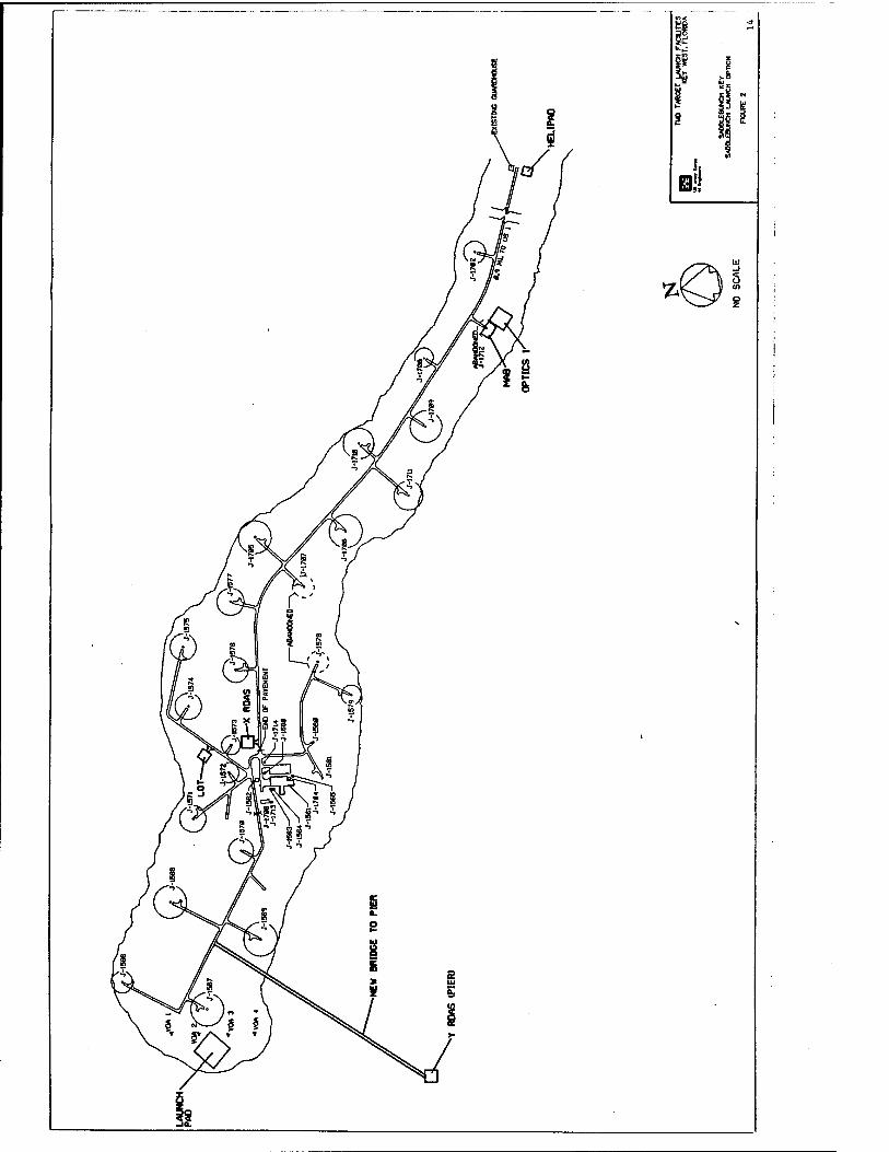
2. Saddlebunch Key: The project area is currently used for U.S Naval Electronics transmission and surveillance. The area has a well developed road system which provides access to most of the site.
a. Launch Pad Complex: The Launch Pad Complex is to be located in the area west of Voice of America (VOA) towers 2 and 3. It will require the upgrading of a narrow gravel road to a wider paved road and the construction of a new road for launch pad access. The upgrading and new construction of the roads will require the addition of several culverts as well as the replacement of two existing culverts. The area will also require some clearing and grubbing.
b. Launch Equipment Room: The Launch Equipment Room will be located in the launch complex area and requires no additional site work.
c. Environmental Shelter: The Environmental Shelter will be located in the launch complex area and requires no additional site work.
d. Launch Operations Trailer (LOT) Shelter: The LOT Shelter will be located northeast of antenna site J-1572. This site may require some cut and fill and it will require clearing and grubbing. A new access road will be constructed and 5 new parking spaces provided.
e. Missile Assembly Building (MAB): The MAB is to be located on the abandoned antenna site J-1712. Clearing and grubbing will be required for the building and the concrete apron and for 5 new parking spaces. The existing road to the site will be used for access.
f. Range Control: Range Control will be located on Fleming Key. The existing hardstand will be used for trailer parking and operations. No site work is required.
g. X RDAS: The X RDAS is to be located northeast of the Administration Building in the curve of the road. Clearing and grubbing will be necessary at the site as well as the construction of a new access road.
h. Y RDAS: The Y RDAS will be located southwest of the VOA towers in wetlands. The area will require the construction of a new access road and a bridge through wetlands. This location for the Y RDAS will also require the construction of a new pier in wetlands.
i. Optics 1: The Optics 1 site will be located near the MAB at abandoned antenna site J-1712. Additional clearing and grubbing will be required for the new pad. The existing road will be used for access.
11

j. Optics 2: The Optics 2 site will be located at the maintenance facility area on Cudjoe Key. No clearing and grubbing will be required and existing roads will be used for access. This site may require the demolition of one of the existing buildings.
k. Radar 1: The Radar 1 site will be located on Fleming Key near Range Control. The existing hardstand will be used for parking and operations. No site work will be required.
1. Radar 2: The Radar 2 site will be located at the maintenance facility area on Cudjoe Key near the Optics 2 site. No clearing and grubbing will be required and existing roads will be used for access. This site may require the demolition of existing buildings.
m. Helipad: The helipad is to be located inside the outer gate opposite the existing guardhouse. The helipad will require clearing and grubbing and the construction of a new 50' x 50' bituminous pavement pad as well as an access road to the area. No new parking is required.
n. Guardhouse: The existing guardhouse will be used. No site work will be required.
12
i m h
0i!
§3 B
UJ -i <r u

m i§
.*SJ
s?
o
ft

N

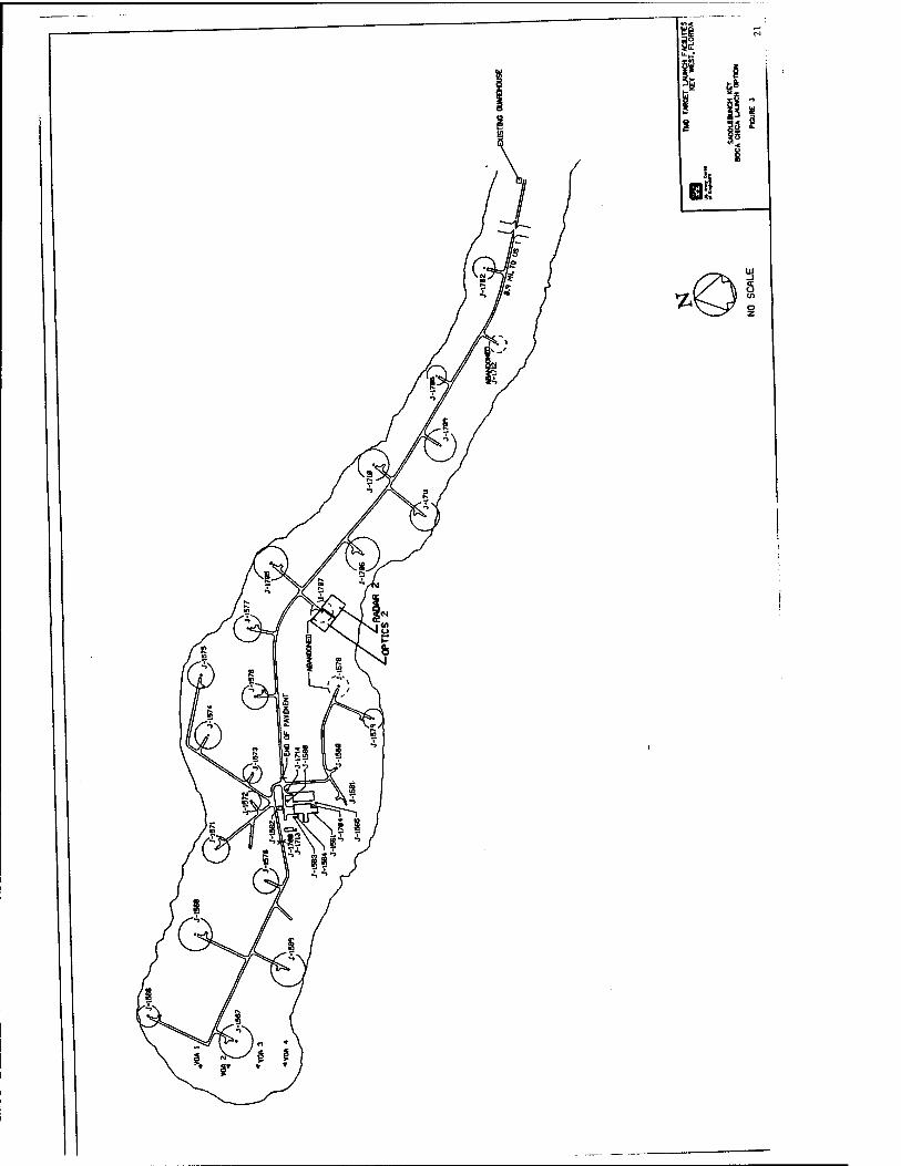
3. Boca Chica Key: The project is the former location of a Hawk missile launch site. The area has a well developed road system which provides access to most of the site. Some of the roads may need to be widened or relocated to accommodate the turning radius of the Transporter/Erector. Some tree cutting may be required to obtain line of site to the launch pad from instrumentation and RDAS sites. Additional tree cutting may be necessary on the main access road to the site to provide clear access for the Transporter/Erector.
a. Launch Pad Complex: The launch pad complex is to be located in the northeast corner of the Hawk site. This site will require the leveling of an existing berm. Existing access roads will be used, new parking may be needed after removal of the berms.
b. Launch Equipment Room: The Launch Equipment Room will be located in the launch complex area and requires no additional site work.
c. Environmental Shelter: The Environmental Shelter will be located in the launch complex area and requires no additional site work.
d. Launch Operations Trailer (LOT) Shelter: The LOT Shelter will be located in the southwest corner of the Hawk site. This site will also require the leveling of an existing berm. Existing roads will be used for access and no new parking will be required.
e. Missile Assembly Building (MAB): The MAB is to be located outside the inner entry gate at least 1250' from the launch pad. This site will require clearing and grubbing as well as the construction of a new access road and 5 new parking spaces.
f. Range Control: Range Control will be located on Fleming Key. The existing hardstand will be used for trailer parking and operations. No site work is required.
g. X RDAS: The X RDAS is to be located near the NAS turnoff on Route 1. Clearing and grubbing will be needed as well as a new access road. No new parking will be required.
h. Y RDAS: The Y RDAS will be located on a pier east of Dredger's Key. A new access road will need to be constructed as well as a new pier.
i. Optics 1: The Optics 1 site will be located on Dredger's Key. Construction will include clearing and grubbing and a new access road. No new parking will be needed.
j. Optics 2: The Optics 2 site will be located on an abandoned antenna site (J- 1707) on Saddlebunch Key. Clearing and grubbing will be required. The existing road to the site will be used for access and no new parking will be needed.
17

k. Radar 1: The Radar 1 site will be located on Fleming Key near Range Control. The existing hardstand will be used for parking and operations. No site work will be required.
1. Radar 2: The Radar 2 site is to be located on an abandoned antenna site (J- 1707) on Saddlebunch Key near the Optics 2 site. Additional clearing and grubbing will be required. The existing road will be used for access and no new parking will be needed.
m. Helipad: The existing helipad on the Hawk site will be used. No site work will be required.
n. Guardhouse: The guardhouse will be located outside the outer gate. Clearing and grubbing will be needed as well as the construction of 5 new parking spaces.
18

IS 11
I 3
s* -
ii

PI o
i eg
»■I.-
6g
h u o KE
Y
OP
TIO
N
2
3 is K
8S
II!
%

N

PART III FACILITY REQUIREMENTS
A. LAUNCH PAD
1. Architectural and Structural
a. Floor Plan: Launch Pad and surrounding paved apron area, with rails and foundations for Environmental Shelter.
(1) New Design: Yes
(2) Standard Plan: No
(3) Site Adaption: No
b. Personnel Occupancy: Launch Pad area is occupied intermittently during missile preparation operations. Area is not occupied during launch.
c. Functional and Operational Characteristics:
(1) Floors:
(a) Type of Floor: Reinforced concrete launch pad and apron.
(b) Type of Floor Finish: Steel trowel finish.
(2) Installed Building Equipment: To be determined (TBD).
(3) Mission Equipment:
(a) Equipment List: Launch stool; other equipment TBD
(b) Furnished By: TBD. Installed By: TBD.
(c) Foundation and Vibration Isolation Requirements: TBD.
(4) Structural Specialties: Slope apron to drain.
(5) Special Structural Features:
(a) Wind Load Criteria: Basic wind speed - 115 mph, Exposure D.
(b) Snow Load Design Criteria: N/A.
23

(c) Seismic Design Criteria: Seismic Zone 0, design in accordance with TM 5-809-1.
(d) Blast and Radiation Design: N/A.
(e) Blast Design: Design launch pad to resist overpressure and thermal effects from launch plume and accidental explosion of missile. Design environmental shelter foundations and rails to resist launch plume overpressures with shelter in retracted position. Launch plume effects TBD.
(f) Special or Unusual Loading, such as Fork Lifts or Wheel Loading and Other Critical Loads on Floor Slabs: 64,000 pound missile and transporter erector; wheel loads TBD. Missile stool launcher; loads TBD.
(6) Other Special Requirements: Facility not designed to accommodate the physically handicapped.
2. Mechanical: No special requirements.
3. Electrical
a. Functional and Operational Characteristics:
(1) Lightning Protection Required: Yes
(2) Emergency Standby Power: No
(3) Electronic Shielding: No
(4) Explosion Proof Requirements: Yes
b. Power Supply:
(1) Voltages: 480 and 120/208 volts
(2) Phases: Three and single
(3) Additional Information: Mission equipment list is attached. Power for the launch pad and environmental shelter is provided from the Launch Equipment Room (LER). The following will also be provided:
(a) Umbilical box and two junction boxes at the launch pad
24
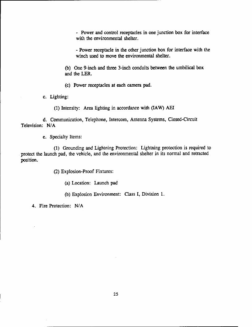
- Power and control receptacles in one junction box for interface with the environmental shelter.
- Power receptacle in the other junction box for interface with the winch used to move the environmental shelter.
(b) One 9-inch and three 3-inch conduits between the umbilical box and the LER.
(c) Power receptacles at each camera pad.
c. Lighting:
(1) Intensity: Area lighting in accordance with (IAW) AEI
d. Communication, Telephone, Intercom, Antenna Systems, Closed-Circuit Television: N/A
e. Specialty Items:
(1) Grounding and Lightning Protection: Lightning protection is required to protect the launch pad, the vehicle, and the environmental shelter in its normal and retracted position.
(2) Explosion-Proof Fixtures:
(a) Location: Launch pad
(b) Explosion Environment: Class I, Division 1.
4. Fire Protection: N/A
25
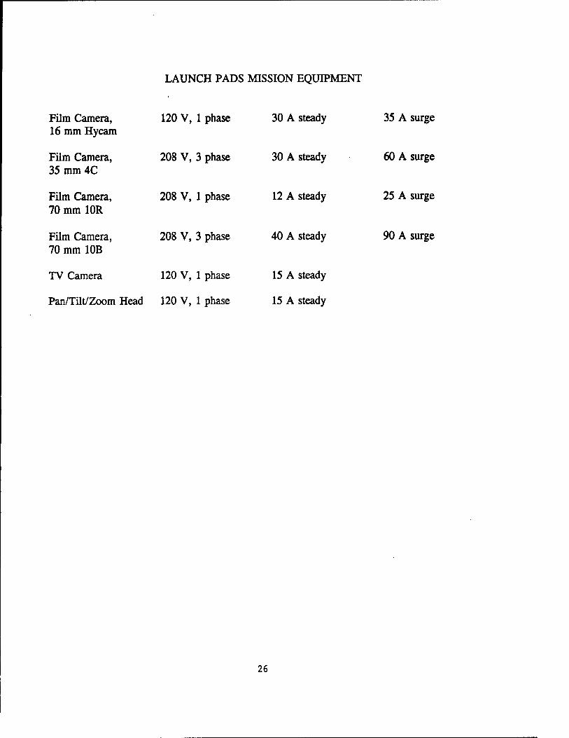
LAUNCH PADS MISSION EQUIPMENT
Film Camera, 120 V, 1 phase 30 A steady 35 A surge 16 mm Hycam
Film Camera, 208 V, 3 phase 30 A steady 60 A surge 35 mm 4C
Film Camera, 208 V, 1 phase 12 A steady 25 A surge 70 mm 10R
Film Camera, 208 V, 3 phase 40 A steady 90 A surge 70 mm 10B
TV Camera 120 V, 1 phase 15 A steady
Pan/Tilt/Zoom Head 120 V, 1 phase 15 A steady
26
27

B. LAUNCH EQUIPMENT BUILDING (LEB)
1. Architectural and Structural
a. Floor Plan:
(1) New Design: Yes
(2) Standard Plan: No
(3) Site Adaption: No
b. Personnel Occupancy:
(1) Intermittently occupied during launch preparation, not occupied during launch
c. Functional and Operational Characteristics:
(1) Floors:
(a) Type of Floor: Concrete
(b) Type of Floor Finish: Steel trowel finish
(2) Walls:
(a) Exterior Walls: Concrete
1. Exposed Surface Materials: Concrete
2. Materials should not match surrounding buildings
(b) Interior Walls and Partitions:
I. Finish: Painted concrete
(3) Ceilings:
(a) Height: 8'-0"
(b) Finish: Painted concrete
(4) Doors:
28
(a) Type: Blast resistant
(b)Size: 4'-0" x 7'-0M
(c) Power Operated: No
(d) Locks: Security lock
(e) Location: As shown on sketch
(f) Additional Information: Design to resist missile launch plume and accidental explosion effects; blast effects to be determined.
(5) Hardware:
(a) Keying Requirements: Compatible with program facility requirements
sections.
(b) Installation Master Keying System: Yes
(6) Sound Control: N/A
(7) Storage: N/A
(8) Installed Building Equipment: Refer to Mechanical and Electrical
(9) Mission Equipment: Refer to attached list
(10) Structural Specialties: N/A
(11) Special Structural Features:
(a) Wind Load Criteria: Basic wind speed - 115 mph, exposure D
(b) Snow Load Design Criteria: N/A
(c) Seismic Design Criteria: Seismic zone 0, design in accordance with TM 5-809-10
(d) Blast and Radiation Design: N/A
(e) Blast Design: Design roof, door and exposed walls to resist missile launch plume effects and accidental explosion, effects to be determined.
29

(12) Other Special Requirements: Facility not designed to accommodate the physically handicapped
2. Mechanical
a. Functional and Operational Characteristics:
(1) Heating required: Yes
(2) Air Conditioning required: Yes
(a) Total facility: Yes
(b) Partial (Indicate areas): N/A
(3) Evaporative cooling: N/A
(4) Heating and cooling source:
Central plant: N/A
Self-contained plant: Heat pump(s) will be used.
b. Indoor Design Conditions:
(1) Heating and ventilation:
(a) Inside design temperatures: 68°F
(b) Relative humidity: N/S/R
(2) Air Conditioning or Evaporative Cooling:
(a) Inside design temperature: 74°F
(b) Relative humidity: N/S/R
(c) Heat generated by installed building equipment: No information provided. A conservative estimate will be used in the design.
(3) Refrigeration: N/A
c. Plumbing Fixtures: N/A.
30
d. Specialty Items: N/A
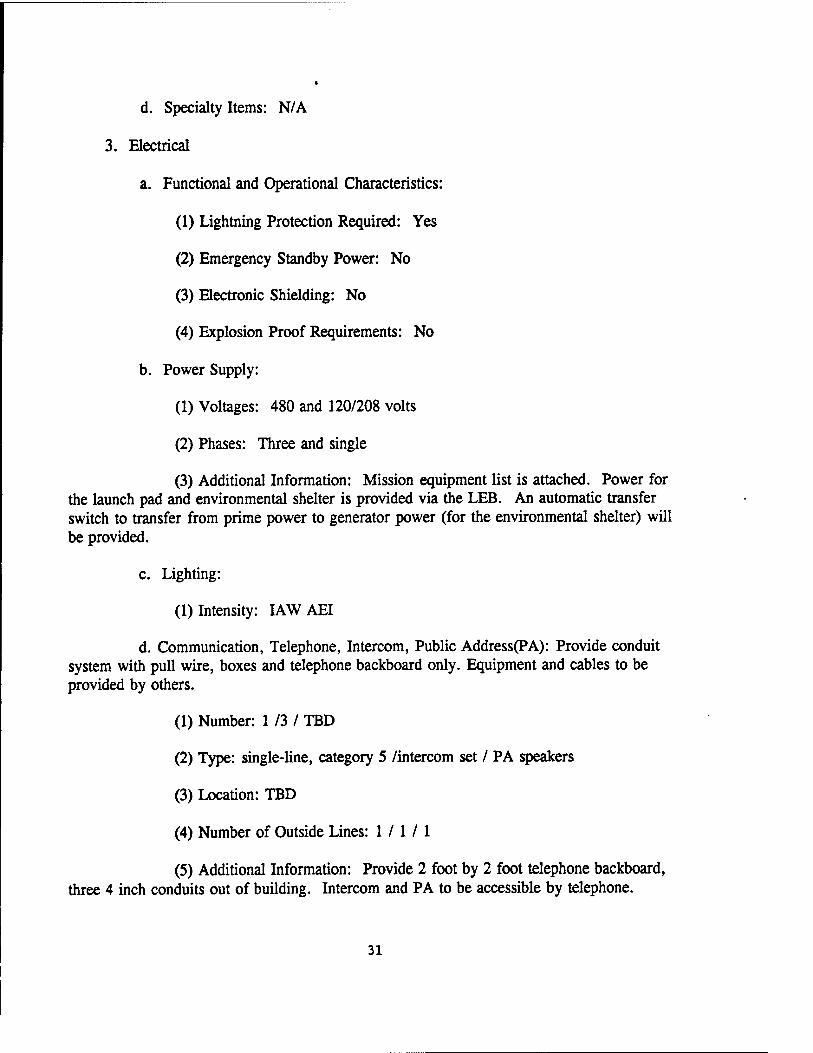
3. Electrical
a. Functional and Operational Characteristics:
(1) Lightning Protection Required: Yes
(2) Emergency Standby Power: No
(3) Electronic Shielding: No
(4) Explosion Proof Requirements: No
b. Power Supply:
(1) Voltages: 480 and 120/208 volts
(2) Phases: Three and single
(3) Additional Information: Mission equipment list is attached. Power for the launch pad and environmental shelter is provided via the LEB. An automatic transfer switch to transfer from prime power to generator power (for the environmental shelter) will be provided.
c. Lighting:
(1) Intensity: IAW AEI
d. Communication, Telephone, Intercom, Public Address(PA): Provide conduit system with pull wire, boxes and telephone backboard only. Equipment and cables to be provided by others.
(1) Number: 1 /3 / TBD
(2) Type: single-line, category 5 /intercom set / PA speakers
(3) Location: TBD
(4) Number of Outside Lines: 1/1/1
(5) Additional Information: Provide 2 foot by 2 foot telephone backboard, three 4 inch conduits out of building. Intercom and PA to be accessible by telephone.
31
e. Specialty Items:
(1) Grounding and Lightning Protection: N/S/R
4. Fire Protection: N/A
32
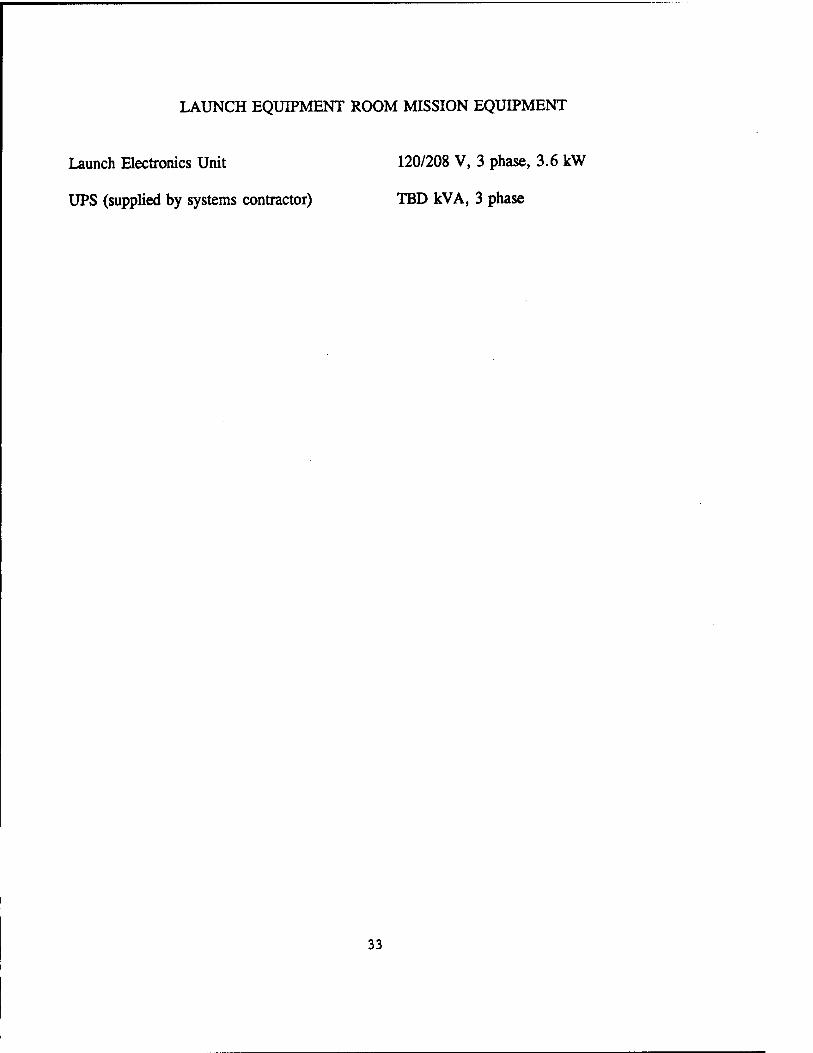
LAUNCH EQUIPMENT ROOM MISSION EQUIPMENT
Launch Electronics Unit 120/208 V, 3 phase, 3.6 kW
UPS (supplied by systems contractor) TBD kVA, 3 phase
33
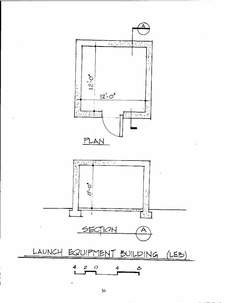
PLAN
"to!
f
e&cpoH
LAUNCH EQUIPMENT feOlLPIN^ ft.Ef,'
4 2 o
34

C. LAUNCH OPERATION TRAILERS SHELTER (LOT)
1. Architectural and Structural
a. Floor Plan:
(1) New Design: YES. Refer to sketch for design of the hardened structure to house and protect three launch control vans with covered parking for 4 additional trailers adjacent to the structure.
b. Personnel Occupancy: 20 people.
c. Functional and Operational Characteristics:
(1) Floors:
(a) Type of Floor: Concrete slab
(b) Type of Floor Finish: Standard smooth finish
(2) Walls:
(a) Exterior Walls:
1. Exposed Surface Materials: Concrete/metal siding
2. Materials need not match surrounding buildings
(b) Interior Walls and Partitions:
1. Finish: Concrete unfinished. Remove fins, fill tie holes and repair any honeycomb.
(3) Roof and Ceilings:
(a) Height: 16'-0" +
(b) Finish: Concrete unfinished/metal siding
(4) Windows: N/A
(5) Doors: N/A
(6) Hardware: N/A
35
(7) Sound Control: N/A
(8) Installed Building Equipment: Ventilation fans
(a) Equipment List: Refer to Mechanical and Electrical sections
(b) Furnished By: Construction contractor Installed By: Construction contractor
(10) Mission Equipment: Launch control vans
(a) Equipment List: missile contractor
(b) Furnished By: missile contractor Installed By: missile contractor
(c) Foundation and Vibration Isolation Requirements: TBD
(11) Structural Specialties: N/A
(12) Special Structural Features:
(a) Wind Load Criteria: Basic wind speed 115 mph, Exposure D.
(c) Seismic Design Criteria: Seismic zone 0.
(d) Blast and Radiation Design: N/A
(e) Blast Design: Design structure to resist accidental missile explosion effects (17,525 pounds, Class 1.1) at launch pad, and missile fragment/debris impact effects (TBD).
(f) Special or Unusual Loading, such as Fork Lifts or Wheel Loading and Other Critical Loads on Floor Slabs: Design floor slab for nominal tractor trailer wheel loads, WB-40 AASHTO design vehicle.
(13) Other Special Requirements: Facility not designed to accommodate the physically handicapped.
2. Mechanical
a. Functional and Operational Characteristics:
(1) Heating required: No
36
(2) Air Conditioning required: No
(3) Evaporative cooling: N/A
(4) Heating and cooling source: N/A
(5) Special functional requirements: N/A
b. Indoor Design Conditions:
(1) Ventilation:
(a) Inside design temperatures: 99°F
(b) Relative humidity: N/S/R
(c) Special or ventilation requirements: Ventilation will be sized to maintain design temperature including heat dissipated and air flow rate required by trailer air conditioning condensing units and all additional heat generated by trailers.
(2) Refrigeration: N/A
c. Plumbing Fixtures: N/A.
3. Electrical
a. Functional and Operational Characteristics:
(1) Lightning Protection Required: Yes
(2) Emergency Standby Power: No
(3) Electronic Shielding: No
(4) Security Systems: No
(5) Explosion Proof Requirements: No
(6) Other Special Systems: Provide two 4 inch capped conduits through roof for antenna connection.
b. Power Supply:
(1) Voltages: 120/208 volts
37
(2) Phases: Three
(3) Additional Information: Provide a disconnect switch for each of the launch operations vans. A common power cable tray shall be furnished at the open side of the structure and a common data cable tray with hooks shall be furnished at the closed side of the structure along the retaining wall. Provide 3 duplex outlets (1 per bay) along the long wall of the building interior.
c. Lighting: Provide lighting inside this structure to illuminate between the trailers. Also provide lighting on the exterior of this structure adjacent to the 4 trailers not in the hardened shelter.
d. Communication, Telephone, Antenna Systems, Closed-Circuit Television: Provide conduit system with pull wire, boxes and telephone backboard only. Equipment and cables to be provided by the Government.
(1) Additional Information: Provide 4 foot by 4 foot telephone backboard, eight 4 inch PVC conduits out of building.
4. Fire Protection: N/A
38
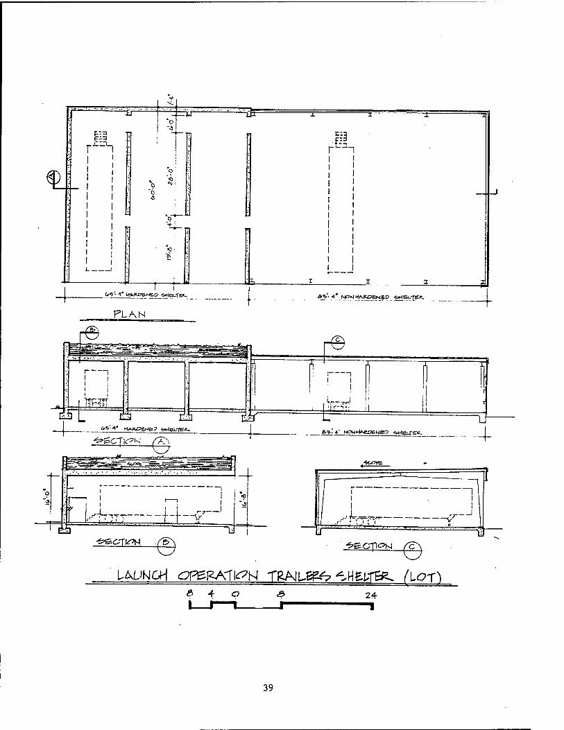
f)_
-if
m ^
C -5
' *• —i
r—i
^l\4^_N??*!i*M*N6P ■feH&,-{ER.
PLAN
o
^ecrpg»M
UUNGH OpggATkPN TRAILS^ ^HfelfER» fior) & A- a & 24
J 1
39
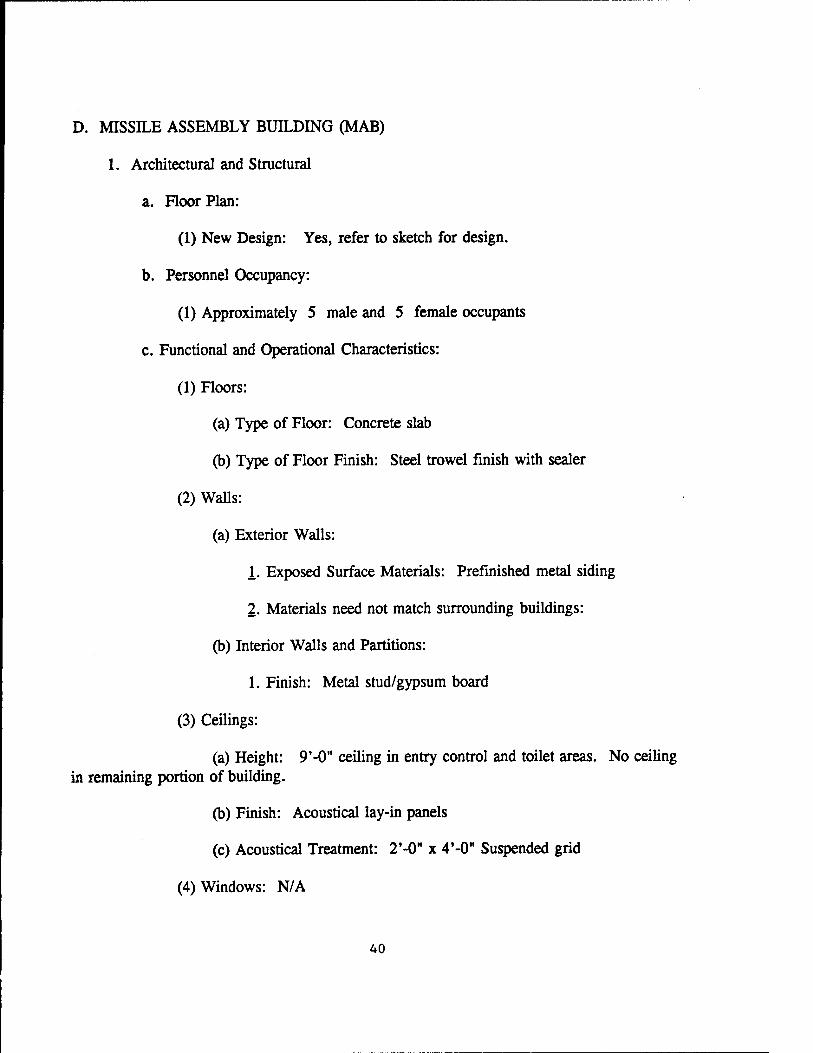
D. MISSILE ASSEMBLY BUILDING (MAB)
1. Architectural and Structural
a. Floor Plan:
(1) New Design: Yes, refer to sketch for design.
b. Personnel Occupancy:
(1) Approximately 5 male and 5 female occupants
c. Functional and Operational Characteristics:
(1) Floors:
(a) Type of Floor: Concrete slab
(b) Type of Floor Finish: Steel trowel finish with sealer
(2) Walls:
(a) Exterior Walls:
1. Exposed Surface Materials: Prefinished metal siding
2. Materials need not match surrounding buildings:
(b) Interior Walls and Partitions:
1. Finish: Metal stud/gypsum board
(3) Ceilings:
(a) Height: 9'-0" ceiling in entry control and toilet areas. No ceiling in remaining portion of building.
(b) Finish: Acoustical lay-in panels
(c) Acoustical Treatment: 2'-0" x 4'-0" Suspended grid
(4) Windows: N/A
40

(5) Doors:
(a) Type: Personnel/overhead
(b) Size: 3'-0" x 7'-0" / 16'-0" high x 24'-0" wide
(c) Power Operated: Personnel - No / Overhead - Yes
(d) Locks: Security Lock
(e) Location: As shown on sketch
(6) Hardware:
(a) Special Security Requirements: N/S/R
(b) Keying Requirements: Compatible with program facilities
(c) Installation Master Keying System: Yes
(7) Sound Control: N/S/R
(8) Storage:
(a) Operational Requirements: Missile parts and equipment
(b) Material Stored: Missile & transporter parts & tools
(c) Vaults: Size and Location: N/A
(9) Installed Building Equipment: Refer to Mechanical and Electrical
(c) Stairs, Elevators, Chutes: N/A
(d) Cranes and Hoists: One crane, characteristics as described below. Hazardous classification requirements, if any, will be coordinated with electrical.
1. Loads: 15 ton capacity bridge crane, 16' hook height
2. Controls: Hoist speed: 20 fpm, Trolley speed: 75 fpm, Bridge speed 150 fpm. Note: All speeds are with crane at rated load and should be variable from 0 to the speed listed above.
41
sections

3. Uses: For missile assembly, missile motor handling
4. Maneuverability: The crane shall be maneuverable over the maximum amount possible of the bay served.
(10) Mission Equipment: Refer to attached list
(11) Structural Specialties:
(c) Sumps: Slope floors to drains in missile bay and mechanical equipment rooms. Provide containment sumps for any spills in the missile bay.
(12) Special Structural Features:
(a) Wind Load Criteria: Basic wind speed - 115 mph, exposure D
(b) Snow Load Design Criteria: N/A
(c) Seismic Design Criteria: Seismic zone 0
(d) Blast and Radiation Design: N/A
(e) Blast Design: N/A
(f) Special or Unusual Loading, such as Fork Lifts or Wheel Loading and Other Critical Loads on Floor Slabs: Floor slabs in missile bays to support 64,000 pound missile transporter/erector (wheel loads TBD), trailer truck,fork lift (6000 pound minimum capacity)
(13) Other Special Requirements: Facility not designed to accommodate the physically handicapped.
2. Mechanical
a. Functional and Operational Characteristics:
(1) Heating required: Yes
(2) Air Conditioning required: Yes, total facility
(3) Evaporative Cooling: N/A
(4) Heating and cooling source: Heat pump(s) will be used.
42
(5) Special functional requirements: Hazardous classification requirements will be coordinated with electrical. Missile must be maintained between 60°F and 80°F.
b. Indoor Design Conditions:
(1) Heating and ventilation:
(a) Inside design temperatures: 68°F
(b) Relative humidity: Humidity cannot be accurately controlled without water.
without water.
(c) Special heating or ventilation requirements: N/A
(2) Air Conditioning or Evaporative Cooling:
(a) Inside design temperature: 74°F
(b) Relative humidity: Humidity cannot be accurately controlled
(c) Heat generated by installed building equipment: No information provided. A conservative estimate will be used in the design.
(3) Refrigeration: N/A
c. Plumbing Fixtures: N/A. No water is available, therefore any items necessary, including combination emergency showers/eyewash fountains, must be portable units, furnished by the systems contractor, if required.
d. Specialty Items:
(1) Compressed air:
(a) Number of outlets: 5 in Assembly Bay
(b) Type of outlets: Quick disconnect
(c) Pressure requirements (cfm @ psi): 300 cfm @ 100 psi
(2) Special gases or vacuum: N/A
3. Electrical
43

a. Functional and Operational Characteristics:
(1) Lightning Protection Required: Yes
(2) Emergency Standby Power: Yes
(3) Electronic Shielding: No
(4) Security Systems: N/S/R
(5) Explosion Proof Requirements: Yes
b. Power Supply:
(1) Voltages: 480 and 120/208 volts
(2) Phases: Three and single
(3) Additional Information: Mission equipment list is attached.
c. Lighting:
(1) Intensity: IAW AEI
d. Communication, Telephone, Intercom, Public Address(PA), Closed Circuit Television (CCTV): Provide conduit system with pull wire, boxes and backboard only. Cables and equipment provided by others.
(1) Number: TBD
(2) Type: single-line, category 5 / intercom set / PA speakers / CCTV cameras
(3) Location: Tech support and clean room / in hazard areas / in hazard areas / in hazard areas
(4) Number of Outside Lines: TBD
(5) Additional Information: Provide 4 foot by 4 foot backboard in electrical room, six 4 inch conduits out of building. Intercom and PA to be accessible by telephone.
e. Specialty Items:
44

(1) Grounding and Lightning Protection: Provide ground bars along outer wall of missile assembly bay.
(2) Special Controls and Lighting: N/A
(3) Alarm Systems, Intrusion: N/A
(4) Explosion-Proof Fixtures: The hazardous classification is based upon the requirements for a generic facility to be used for more than one program.
(a) Location: Missile assembly bay
(b) Explosion Environment: Class I, Division 2, Groups C & D.
(5) Emergency Power: Diesel generator is required to provide emergency power for the HVAC system in the missile assembly bay only.
4. Fire Protection
a. Sprinkler System: No water supply is available. SSDC and CEHND must jointly prepare a waiver request in order to deviate from applicable criteria for submission to HQUSACE. This waiver should be based on limited duration of usage and nonavailability of water.
(1) Type of hazard: Missile Assembly Building.
(2) Protection for building, contents or personnel: Primarily personnel.
(3) Existing fire protection systems: N/A
(4) Adequacy of water supply: See above.
(5) System subject to freezing temperatures: No.
b. Special Fire Suppression Systems: N/A
45

MISSILE ASSEMBLY BUILDING MISSION EQUIPMENT
15-ton crane Monitor & Telephone
Controller Data Logger
Transporter/Erector 480 V, 3 phase 29 kW
Launch Electronics 208 V, 3 phase 3.6 kW
46
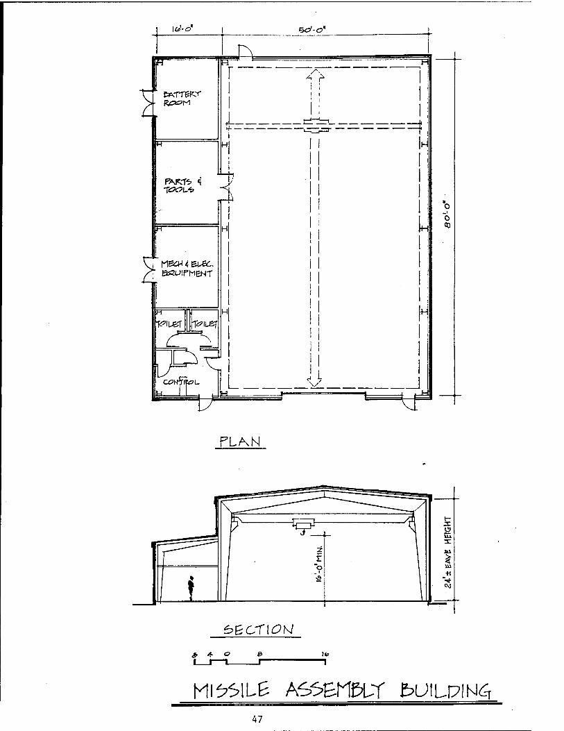
^d-o*
H
r A
P
£ '^iuer
H
■"C COH^OL.
t^ L
fc=L
/>
I i
i>
:=1
H
__1
PL/\N
f?£CT!<2K/
£4-0 «• r -i
MI^51L£ A66&M&LY £>UIL!?!N4 47
E. ENVIRONMENTAL SHELTER
1. Architectural and Structural
a. Floor Plan:
(1) New Design: Yes
(2) Standard Plan: No
(3) Site Adaption: No
b. Personnel Occupancy:
(1) Approximately 6 male and 6 female occupants (permanent and transient).
(2) Approximate number and times of duty hours per day: 8 hrs
c. Functional and Operational Characteristics:
(1) Floors:
(a) Type of Floor: Concrete - Launch pad access ramp with rails
(b) Type of Floor Finish: Steel trowel finished
(2) Walls:
(a) Exterior Walls:
1. Exposed Surface Materials: Structural steel, steel panels w/ rolled insulation
2. Materials need not match surrounding buildings:
(b) Interior Walls and Partitions: N/A
(3) Ceilings:
(a) Height: 50'-0"
(b) Finish: Structural Steel, Steel deck with metal roof
48

requirements
sections.
(c) Acoustical Treatment: N/A
(4) Windows: N/A
(5) Doors:
(a) Type: Folding / Personnel
(b) Size: 49'-0" x 22'-0" / 3'-0H x 7'-0"
(c) Power Operated: Yes / No
(d) Locks: Security lock
(e) Location: As shown on sketch
(6) Hardware:
(a) Special Security Requirements: N/S/R
(b) Keying Requirements: Compatible with program facility
(c) Installation Master Keying System: Yes
(7) Sound Control: N/A
(8) Storage: N/A
(9) Installed Building Equipment: Refer to Mechanical and Electrical
(10) Mission Equipment: TBD
(11) Structural Specialties: N/A
(12) Special Structural Features:
(a) Wind Load Criteria: Basic wind speed - 115 mph, exposure D
(b) Snow Load Design Criteria: N/A
(c) Seismic Design Criteria: Seismic zone 0
49
(d) Blast and Radiation Design: N/A
(e) Blast Design: Design to resist missile exhaust plume overpressures in retracted position; plume effects to be determined.
(f) Special or Unusual Loading, such as Fork Lifts or Wheel Loading and Other Critical Loads on Floor Slabs: 64,000 pound missile and transporter/erector, wheel loads to be determined
(13) Other Special Requirements: Facility not designed to accommodate the physically handicapped.
2. Mechanical
a. Functional and Operational Characteristics:
(1) Heating required: Yes
(2) Air Conditioning required: Total facility
(3) Evaporative cooling: N/A
(4) Heating and cooling source: Through-the-wall heat pumps will be used.
(5) Special functional requirements: Missile must be maintained between 60°F and 80°F.
b. Indoor Design Conditions:
(1) Heating and ventilation:
(a) Inside design temperatures: 68°F
(b) Relative humidity: N/S/R
(2) Air Conditioning:
(a) Inside design temperature: 72°F
(b) Relative humidity: N/S/R
(c) Heat generated by installed building equipment: No information provided. A conservative estimate will be used in the design.
50

(3) Refrigeration: N/A
c. Plumbing Fixtures: N/A. No water is available, therefore any items necessary, including emergency shower/eyewash fountains must be portable units, furnished by the systems contractor, if required.
d. Specialty Items: N/A
3. Electrical
a. Functional and Operational Characteristics:
(1) Lightning Protection Required: Yes
(2) Emergency Standby Power: Yes
(3) Electronic Shielding: No
(4) Explosion Proof Requirements: No
b. Power Supply:
(1) Voltages: 480 and 120/208 volts
(2) Phases: Three and single
(3) Additional Information: The environmental shelter is required to plug into receptacle provided as part of the launch pad.
c. Lighting:
(1) Intensity: IAWAEI
d. Communication, Telephone, Intercom, Antenna Systems, Closed-Circuit Television: N/S/R.
e. Specialty Items:
(1) Explosion-Proof Fixtures: N/A
(2) Emergency Power: Diesel generator is required to provide emergency power for the HVAC system.
4. Fire Protection: N/A
51

ft
l4-c"
J
I
=A=
79-0
z«?-<? &!<>"
I 'T*T
-4 5> o
i o
o
H-
e.\j£V/*a\a\4
gMVlPOMMBMTAU ^Hgl/fE*. to £ J
32. —J
52

F. REAL TIME DATA ACQUISITION SYSTEM (RDAS)
1. Architectural and Structural: N/A
2. Mechanical: N/A
3. Electrical
a. Functional and Operational Characteristics:
(1) Lightning Protection Required: No
(2) Emergency Standby Power: No
(3) Electronic Shielding: No
(4) Security Systems: N/A
(5) Explosion Proof Requirements: No
b. Power Supply:
(1) Voltages: 120/208 volts
(2) Phases: Three
(3) Additional Information: Mission equipment list is attached. In addition, two 15 A receptacles, one single phase and one three phase, will be provided. Exact location to be determined.
c. Lighting:
(1) Intensity: Area lighting IAW AEI
d. Communication, Telephone, Intercom, Antenna Systems, Closed-Circuit Television: N/S/R.
e. Specialty Items: N/A
4. Fire Protection: N/A
53
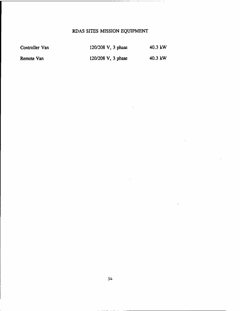
RDAS SITES MISSION EQUIPMENT
Controller Van 120/208 V, 3 phase 40.3 kW
Remote Van 120/208 V, 3 phase 40.3 kW
54

200' CLEAR AREA
T15'TYP
-TELEPHONE POLES TYP. 5'ABOVE GROUND (40'SPACING)
■70'SQUARE CRUSHED AGGREGATE PAD CENTER
-TELEPHONE POLES TYP. 5'ABOVE GROUND
R DAS DETAIL
55
G. RADAR SITE
1. Architectural and Structural: N/A
2. Mechanical: N/A
3. Electrical
a. Functional and Operational Characteristics:
(1) Lightning Protection Required: No
(2) Emergency Standby Power: No
(3) Electronic Shielding: No
(4) Security Systems: No
(5) Explosion Proof Requirements: No
b. Power Supply:
(1) Voltages: 120/208 and 120/240 volts
(2) Phases: Three
(3) Additional Information: Mission equipment list is attached.
c. Lighting:
(1) Intensity: Area lighting IAW AEI
d. Communication, Telephone: N/A
e. Specialty Items: N/A
4. Fire Protection: N/A
56

RADAR SITES MISSION EQUIPMENT
Technical Van 120/208 V, 3 phase 45 kVA
Climatic Van 120/240 V, 3 phase 50 kVA
57
H. OPTICS SITE
1. Architectural and Structural: N/A
2. Mechanical: N/A
3. Electrical
a. Functional and Operational Characteristics:
(1) Lightning Protection Required: No
(2) Emergency Standby Power: No
(3) Electronic Shielding: No
(4) Security Systems: N/A
(5) Explosion Proof Requirements: No
b. Power Supply:
(1) Voltages: 120/208 volts
(2) Phases: Three
(3) Additional Information: Mission equipment list is attached.
c. Lighting:
(1) Intensity: Area lighting IAW AEI
d. Communication, Telephone, Intercom, Antenna Systems, Closed-Circuit Television: N/A
e. Specialty Items: N/A
4. Fire Protection: N/A
58
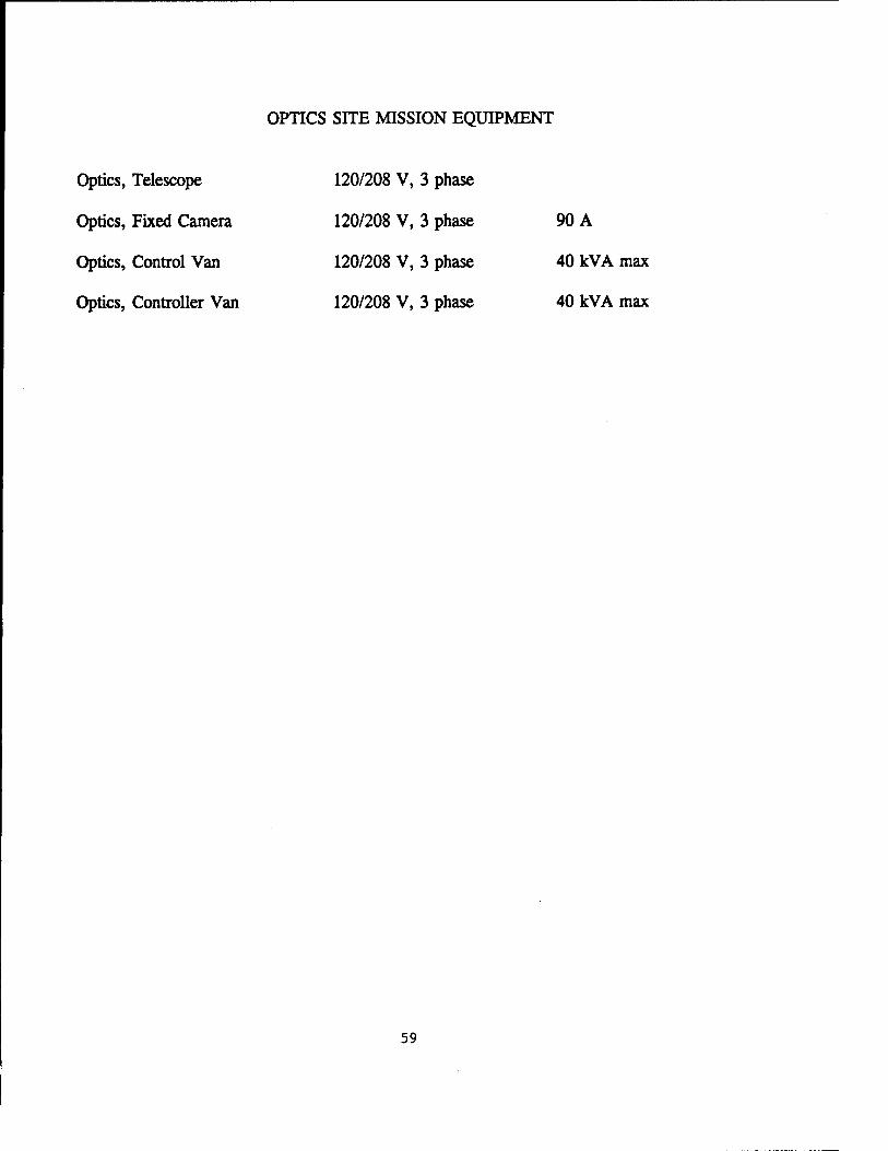
OPTICS SITE MISSION EQUIPMENT
Optics, Telescope
Optics, Fixed Camera
Optics, Control Van
Optics, Controller Van
120/208 V, 3 phase
120/208 V, 3 phase
120/208 V, 3 phase
120/208 V, 3 phase
90A
40 kVA max
40 kVA max
59
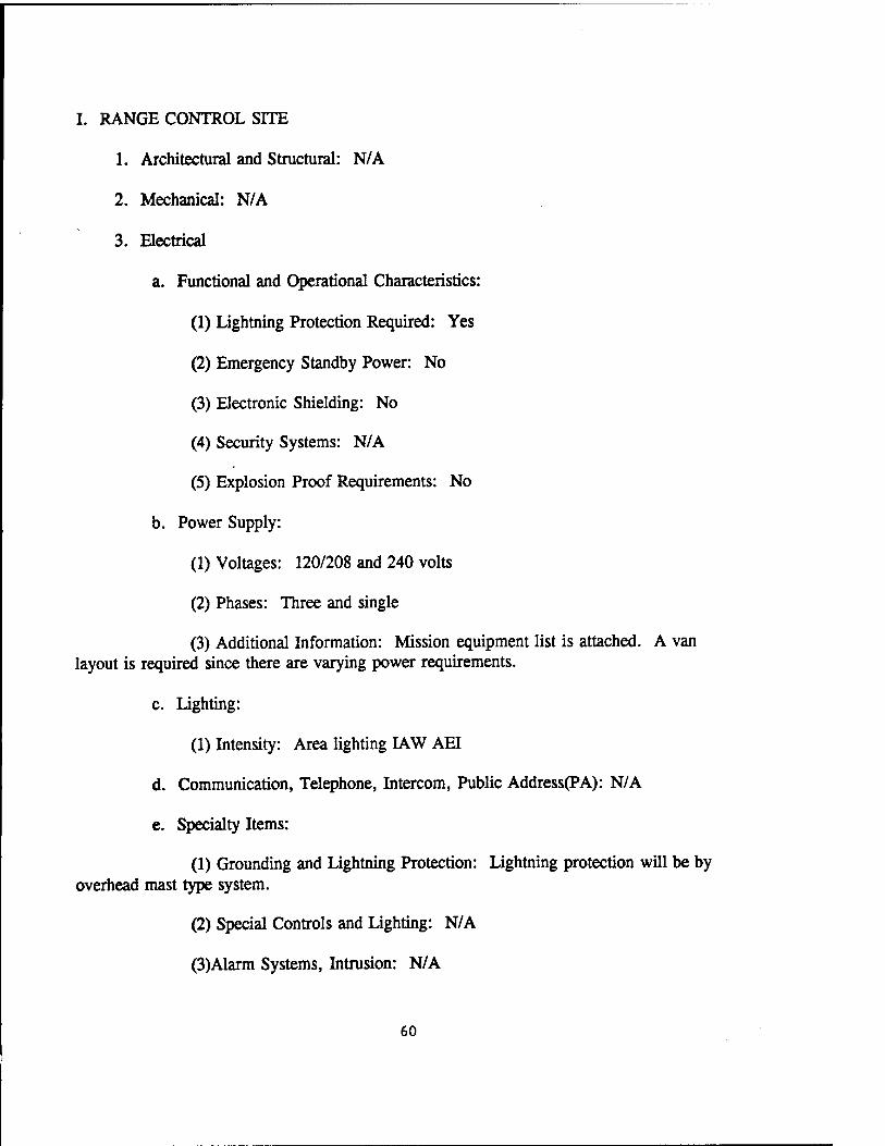
I. RANGE CONTROL SITE
1. Architectural and Structural: N/A
2. Mechanical: N/A
3. Electrical
a. Functional and Operational Characteristics:
(1) Lightning Protection Required: Yes
(2) Emergency Standby Power: No
(3) Electronic Shielding: No
(4) Security Systems: N/A
(5) Explosion Proof Requirements: No
b. Power Supply:
(1) Voltages: 120/208 and 240 volts
(2) Phases: Three and single
(3) Additional Information: Mission equipment list is attached. A van layout is required since there are varying power requirements.
c. Lighting:
(1) Intensity: Area lighting IAW AEI
d. Communication, Telephone, Intercom, Public Address(PA): N/A
e. Specialty Items:
(1) Grounding and Lightning Protection: Lightning protection will be by overhead mast type system.
(2) Special Controls and Lighting: N/A
(3)Alarm Systems, Intrusion: N/A
60
(4) Explosion-Proof Fixtures: N/A
(5) Emergency Power: Battery bank to be supplied by others.
(6) Corrosion Control: N/A
4. Fire Protection: N/A
61
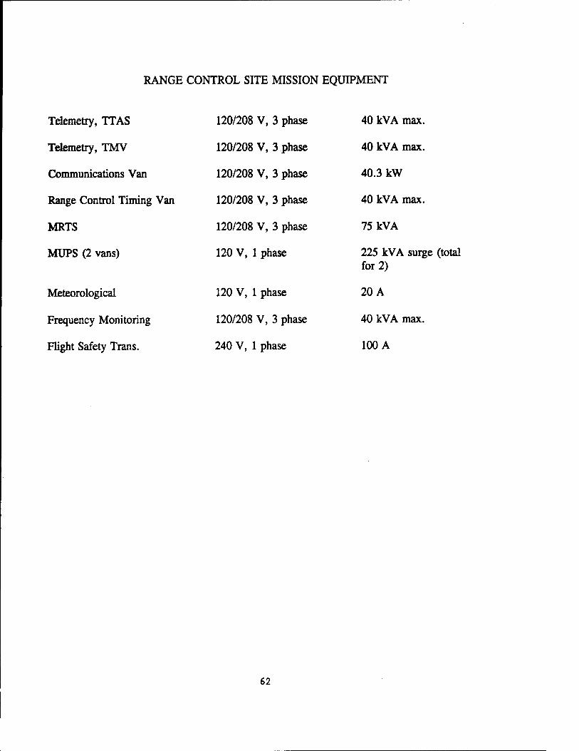
RANGE CONTROL SITE MISSION EQUIPMENT
Telemetry, TTAS 120/208 V, 3 phase 40 kVA max.
Telemetry, TMV 120/208 V, 3 phase 40 kVA max.
Communications Van 120/208 V, 3 phase 40.3 kW
Range Control Timing Van 120/208 V, 3 phase 40 kVA max.
MRTS 120/208 V, 3 phase 75kVA
MUPS (2 vans) 120 V, 1 phase 225 kVA surge (total for 2)
Meteorological 120 V, 1 phase 20 A
Frequency Monitoring 120/208 V, 3 phase 40 kVA max.
Flight Safety Trans. 240 V, 1 phase 100 A
62
J. HELIPAD
1. Architectural and Structural: N/A
2. Mechanical: N/A
3. Electrical
a. Functional and Operational Characteristics:
(1) Lightning Protection Required: No
(2) Emergency Standby Power: No
(3) Electronic Shielding: No
(4) Security Systems: No
(5) Explosion Proof Requirements: No
b. Power Supply: 480 Volts
c. Lighting:
(1) Intensity: Area lighting IAW AEI
d. Communication, Telephone, Intercom, Antenna Systems, Closed-Circuit Television: N/S/R
e. Specialty Items: N/A
4. Fire Protection: N/A
K. GUARDHOUSE
1. Architectural and Structural
a. Floor Plan:
(1) New Design: No
(2) Standard Plan: Preconstructed portable building
63

insulated
(3) Site Adaption: No
b. Personnel Occupancy: Approximately 1 male or 1 female occupant
c. Functional and Operational Characteristics:
(1) Floors:
(a) Type of Floor: Steel tread plate
(b) Type of Floor Finish: Painted steel with traction and cushion pad
(2) Walls:
(a) Exterior Walls:
1. Exposed Surface Materials: N/S/R
2. Materials need not match surrounding buildings:
(b) Interior Walls Surface:
1. Finish: N/S/R
(3) Ceilings:
(a) Height: 8'-0"
(b) Finish: Painted
(c) Acoustical Treatment: None
(d) Additional Information: Roof/ceiling panels to be thermally
(4) Windows:
(a) Type: Fixed
(b) Size: As shown on sketch
(c) Location: As shown on sketch
(d) Special Treatment: Tinted glass to reduce solar load
64
(5) Doors:
(a) Type: Sliding
(b)Size: 3'-0H x 6'-8"
(c) Power Operated: No
(d) Locks: Yes
(e) Location: As shown on sketch
(6) Hardware:
(a) Special Security Requirements: Security lock
(b) Keying Requirements: TBD
(c) Installation Master Keying System: No
(7) Sound Control: N/A
(8) Storage: N/A
(9) Installed Building Equipment: TBD
(10) Mission Equipment: N/A
(11) Structural Specialties: N/A
(12) Special Structural Features:
(a) Wind Load Criteria: Basic wind speed - 115 mph, exposure D
(b) Snow Load Design Criteria: N/A
(c) Seismic Design Criteria: Seismic zone 0
(d) Blast and Radiation Design: N/A
(e) Blast Design: N/A
(f) Special or Unusual Loading: N/A
65
(13) Fallout Protection: N/A
(14) Other Special Requirements: Facility not designed to accommodate the physically handicapped.
2. Mechanical
a. Functional and Operational Characteristics:
(1) Heating required: Yes
(2) Air Conditioning required: Total facility
(3) Evaporative cooling: N/A
(4) Heating and cooling source: Through the wall heat pump will be used.
b. Indoor Design Conditions:
(1) Heating and ventilation:
(a) Inside design temperatures: 68°F
(b) Relative humidity: N/S/R
(c) Special heating or ventilation requirements: N/A
(2) Air Conditioning or Evaporative Cooling:
(a) Inside design temperature: 78°F
(b) Relative humidity: N/S/R
(c) Heat generated by installed building equipment: N/A
(d) Special cooling requirements: N/A
(3) Refrigeration: N/A
c. Plumbing Fixtures: N/A.
d. Specialty Items: N/A
3. Electrical
66

a. Functional and Operational Characteristics:
(1) Lightning Protection Required: No
(2) Emergency Standby Power: No
(3) Electronic Shielding: No
(4) Security Systems: N/A
(5) Explosion Proof Requirements: No
b. Power Supply:
(1) Voltages: 120 Volts
(2) Phases: Single
c. Lighting:
(1) Intensity: IAW AEI
d. Communication, Telephone, Intercom, Public Address(PA): Provide conduit with pull wires and boxes only. Equipment and cables to be provided by others.
(1) Number: 1/1/1
(2) Type: single-line, category 5 / intercom /PA speaker
(3) Location: Security counter / security counter wall / on exterior
(4) Number of Outside Lines: 1/1/1
(5) Additional Information: Provide telephone backboard, two 4 inch conduits out of building. Intercom and PA to be accessible from telephone.
e. Specialty Items: N/A
4. Fire Protection: N/A
67
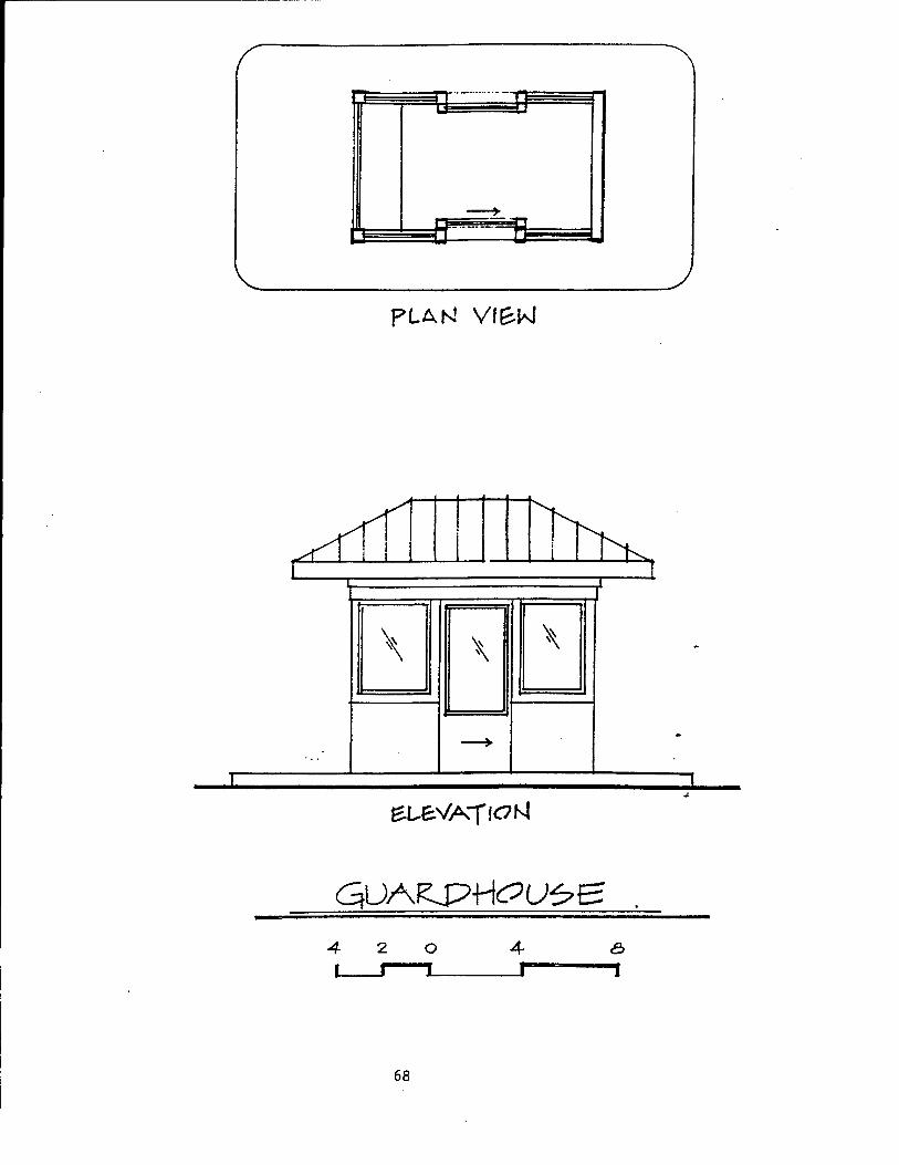
tt
=3=
PLAN! Vl&kJ
i T^ 1. _jl
\ X X
—
euEVAficM
qUAf^pH<?U^g 4 2 O I
4- _r -I
68

Florida Keys Target Launch Siting Report Ballistic Missile Defense Organization
Annex B Launch Hazard Data
B

>-
o Ü
ui 3
i e
Snc/c^

<
2< I— Cß
fn O
»♦*. o CM o o
<
r- CO CO 0)
T1 IO o> (0 CD CO CO
C
5 (0 (0 00 (0 10 CD T" 1—
o jr 1— o <D r^ (11
5 5
CM
T-
o O)
o ■■] n -_ c? ex o I o
1 E o> r- CC
CO D. E > -
-
- ^ a 0) •rH *"* C «J . •ft .,-. c ,o -u *n .. -J»
_
-
o3E. "» -
01 2C (0 3V- c
r*
^
, . t 1 1 1 1 1 1 i 4—"- -H- l_J_J. —"—T 1 i
o
CJ1 CD
TO
CD •a
ID CO > cc
cr en
o en CO C\J CO ^-i
(6sp) aprnuBi 5

DC O H O UJ
cc
S3 |— CO
§2
o ü UJ
<
/,
o
-
m -
-
o o
/ _
/ -
, —
*\
-
-
o o CM
<-> o o CM
i
o m -
1.1 1 1 1 ■J.I 1 1 1 1 1 1 , III!
CL
O O OJ
O O
O O O
o o CD
O O CO
O O
o o to
O O IT)
O O T
O o CO
o o OJ
o o
cu CTJ c ro c_
■o c ID o
CJ3
Ol
> tr cr en
O O m
o in OJ
o o OJ
o in
CD O
CD in
(w>i) apnmiV

o Ü in
oc l-l- -|<2 S3
go
O Ü
4
en
o I—«
QJ
(ui)|) apnqniV
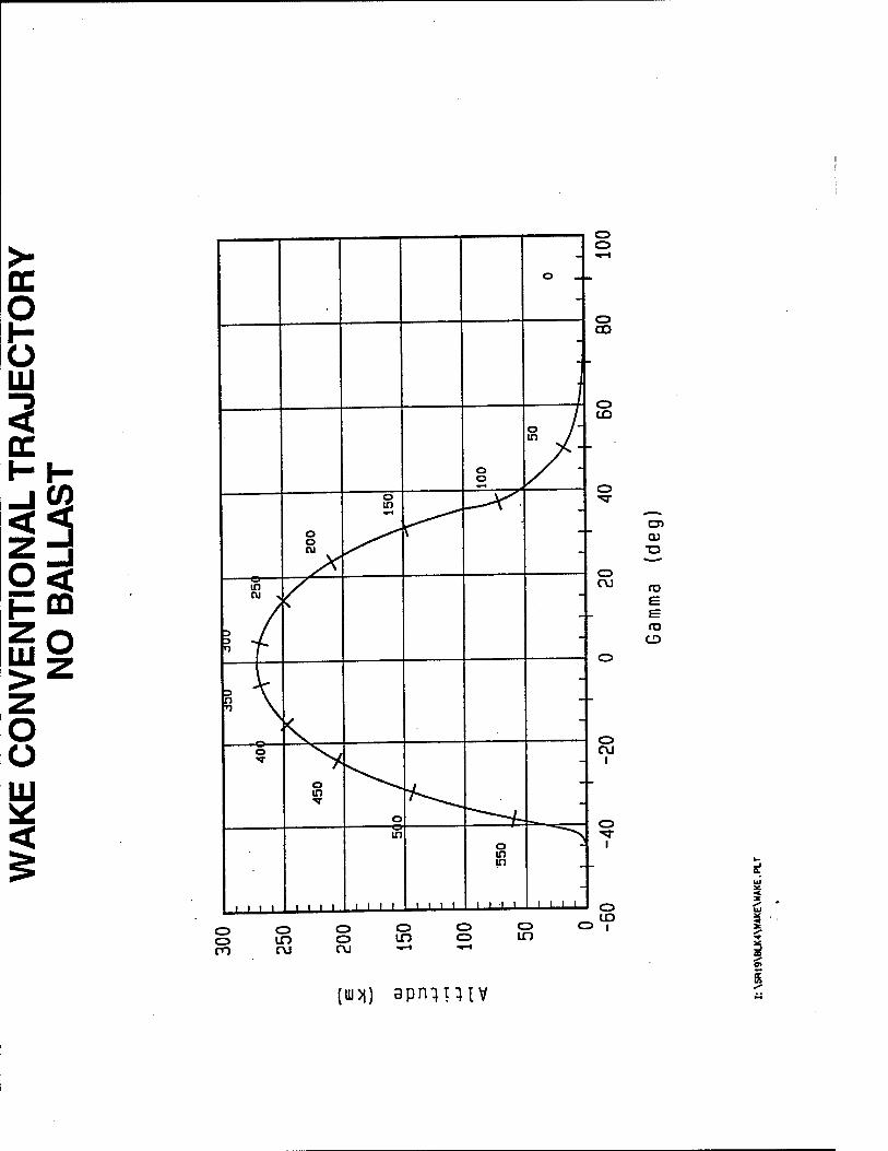
> cc o o UJ
cc
o o SS
o -
O O
in /
o o tu
o in
o in cu ,
3 / 3 -JL
3 \ n \
o
o in V
o
■„LI 1 1 111!
in
III! 1 1 ! 1.
o in m
1 1 1 .!.. III!
o o
C3 CO
o
o
o OJ
en cu
■o
ro
CD CD
o OJ
I
O T
i
UJ
5
C3 CO m
co in OJ
CO o OJ
CO in
o co
CO in
o
(ui5|) apnmtV
LL o Q CO <-
|I ■o en a) .£ CD "O
LL 3 «A ° 5s cb w Sä
CD O) c
.. © s coQ ©
gis g. 2 co c ©cno Q. C -J=
■O 3 (0 a« §■ « CO w Q.j>» P CB CO - c c ^ CO c ?o § <£o © © CD — °>c « CO o ©
OT 0)JD •- c to •♦— •— 4»*
©iS £-g <2 S S.JE
«(flu © C ^ o.2o ** CO CO "© m «- © o O 3 =5 © w e SS * > O o CD E c
a> <D © . Ö O) O) CO 2 £ = 5 Q. « -o .2
> ^ .E co 6 <D C > 11 -B S © a3 3.2 H o5 E ffl
■ G 'to co
co c o
TJ c o o (D
o CD
CO ^ £ CO «*-» Q. CD
5 CO CO — CO *•* cc "c O) a^v c O) CO c 3
'co 3 CO
"co C >> O CO
"co Ü
c CO
o o o CO CO Ü a. E © c CD o O) 2 « t5 O) c ü5 "E •^ o "5 c
TZ CD Q.
E >» o x> c CD c
75 c
E "E o
0) c c a> TJ
O tfl v. ^S CO *•- 3 CO
O CO
c COU. o CD O
JS Q-Q .2 CD
3 "© * E
CO « tL Q. >» >» E"° aS - TJ "co o) 2 CO r- x:
QC .52 a) O) «LL
CO 5 tD S c CO
CEO | CD
E XJ 0)Q C CD CD CD
« E 3 o If U. • JO
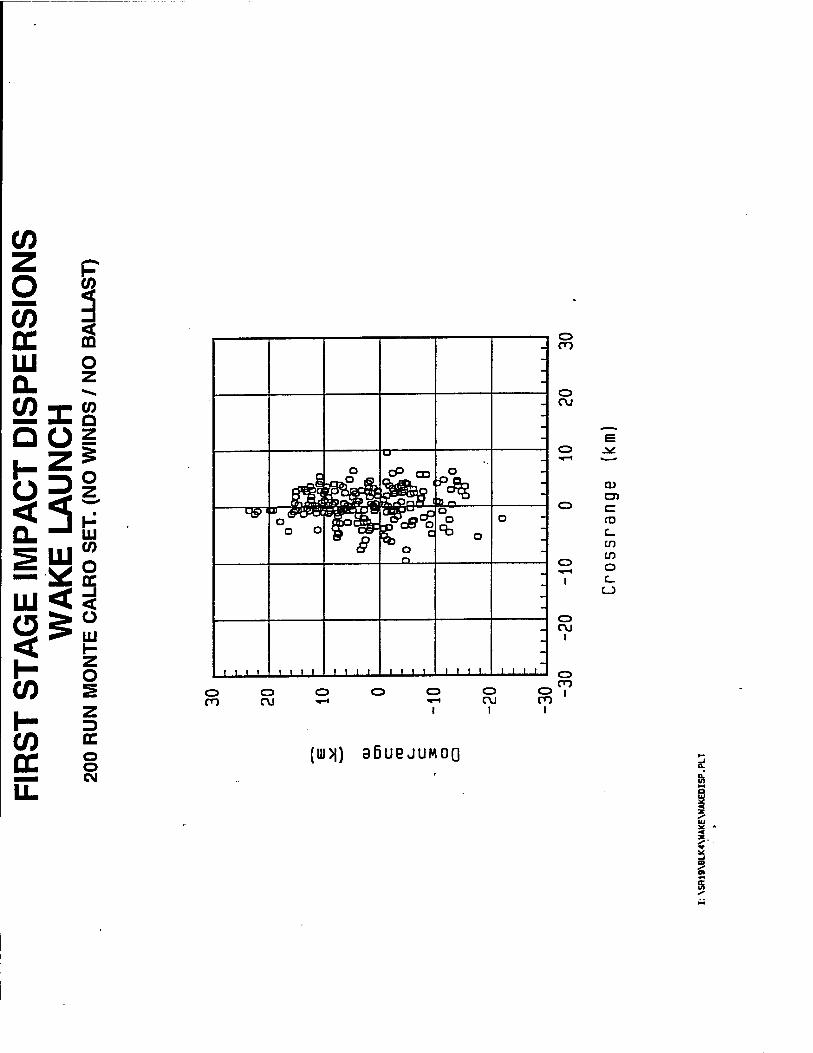
z o en DC Ui Q. V) a
LU
§ (0 I-
cc LL
P CO
3
Q Ü?
O z 3S LU
<< Ü
LU (/>
o
UJ
o o CM
(lü>|) aßUGJUMOQ
tu en c fO c_ m en o c_ o
a!
o
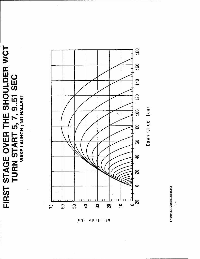
ü
DC go HUJ
8=i5 S= Is- o X nz I— w i" DCI-i WDC3
O I- ö
O z
5 DC H3
DC U.
--
--
--
^»^^
(
^^^-_
I --
'■^"^ --
%!
/
*^~~--
s^^.-
■ III! ,..l_]_l_l_ 1 1 !..!_ 1111 1111 1111 1 1 1 1
o CD
CD CO
o "ST
O
o o
CD CO
CD
o
CD OJ
cu en c CD c_ cr 3: o O
CD o ID
O in
o CD ro
CD OJ
(uj>j) apnmtV

ü
er ü UJ
_ ins COo>i UJ ^m
H mi
UJCCi ><3
Sä
u.
1 1 1
1 / /
/'-
^ v\ / / ;.
>1 \1 / / /;-
t \ 1 /
/;:
1 S"
xA ""
1 ,1,„.I_1 _l 1 1—u i —i i- i— ,_l l_J L_
C\J
CD
CD
CU cn c CD C_ c= s. o O
OJ
Q.
U
O cu in in
OJ i
(ui)|) apn^niV

CL
CO
8 Z QC D I- LU
a Ü H CO DC o
JC Ü
■*—*
'5. CD N
CD N CD O
T3 c O =: O) CO CO 0
>» "o ■0 JO V—
^^s sz ■
CM "O o 0
CD jg .0 *k- CO 0
3 CO 0 CT
o Ü fu
el).
=
1350
> JC 3 E
CO
CO
>» JO
c 0
3
0 E CO c
urne
d ra
ge ß
"N CO
JC
■o 0 5
_o
CO 0
CO
O
CD CO
0 ig u
nb
s (a
vei "I
CD
E
Ö CO c
"co TJ c CO
JC '■5 CD 0 CO
0 c 3 E E CO
"N CO o to CO 5 N
JC c c CO CO , O
I CO CO
— >» CO "Ö CO o
CD JC to
o 5
JC o
c 0
C o
0
CO
irren
t m
a is
sile a
er
CO TJ
■a c
JC *-* 0
as CD
CD 3 CT
O CD
o
0 JC
CO
5 co
0
C CD Ü o 3 E "5
0 c CO
c
Ü CO
"co Ö 4—«
C (hol
d in
tact
CO ** CO ^» CO
CO CO
CO
'E 0
JC o J3
c 0
o
orie
s th
at:
elec
ted
times
. 3
o Ü 0 CO
in
CD
in CO
o Ü
CD IM N O c i
dura
tion
llist
ic w
ith i JC
■•—•
CO CD
O
o CD
CD k- 3
•D CD Ü O k-
0
o 0 c o -a
"6 c o
*—• CO c
JO
0
'S) TJ
"5 0
5 CD sz E
3 E * 2
4-«
CL
JC CO E
o JC
k.
ct t
raje
ct
turn a
t s c
3
CD CO CO
CO CD
JC o ca CD V—
E "x CO
E CO it
end
of
ssum
ing CM
CO c 'ffl
o CO CD CO
CD
CO c o o
o 0 CO ca o
to o
•0 0
JC CO
'Q.T3 0 CD
Ü CD
"CD Ü
CO CO c o
c CO
0 Q.
E •a = en P
to Ü 'sz CO o 3 CO
Ü CO 5 5 0 o Jc CD ^ Q. tr CO co 0 0
g ch
art:
unco
nti 5
CO
CD > CD
>
CD
« E CD ™
CO JC Ü
o Ö CD CO CO
5*
0 N N O
JC o CO
0 CD ••—» 3
JC
I
JC *-* (0 ^ c co
C CO CO 0
JC 0
co 0 CO
<
»win
ta
rt
Ü CD X CD -2^
k_
CO
Ü
to C O
CO
The
follc
LU *
H- LL * «
Eac
h qu
ic
rem
ent
o
CD JC
JC Ü
ca 0 CO
C g o 0
"0 i , .= 1 < "D 1
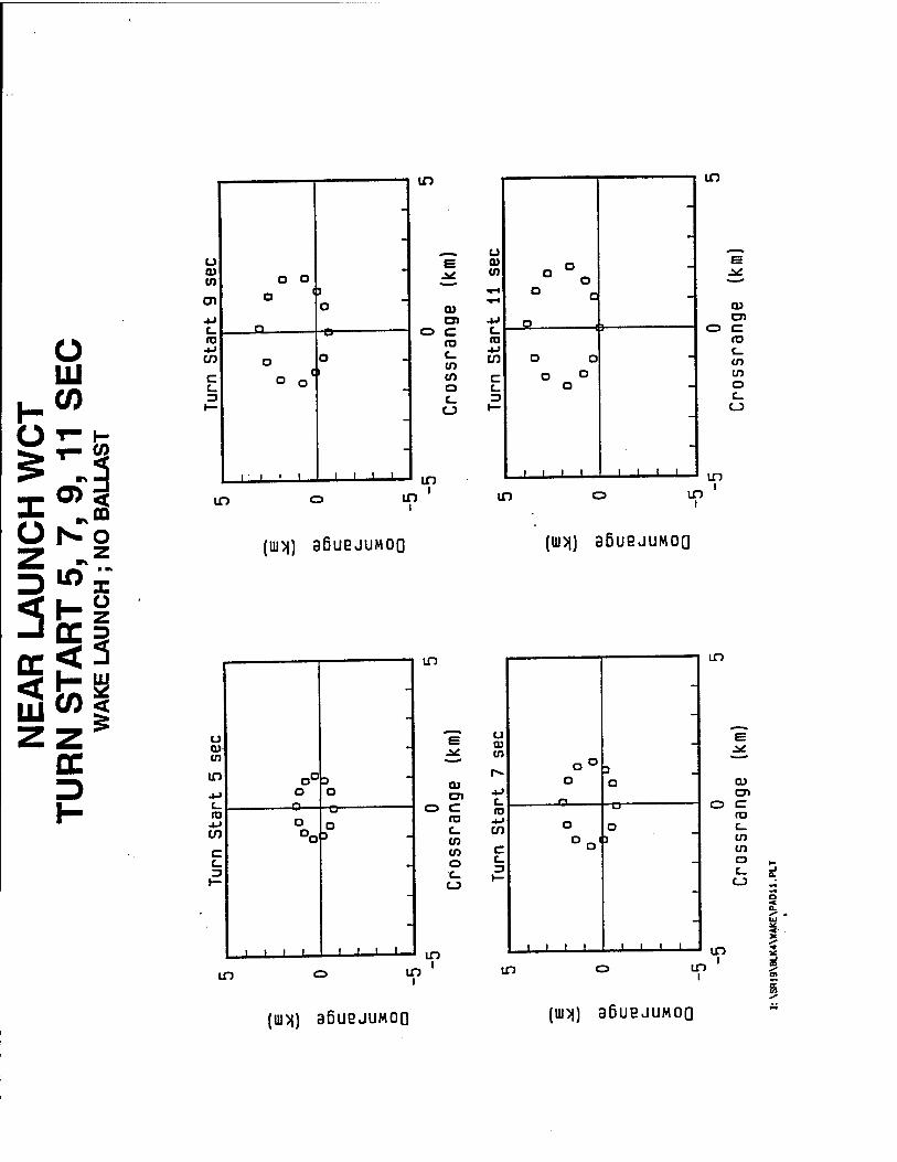
ü LU
Oh-o
3 DC <
10 1-
< I- (0
QC
x ü
SS < HS
-
L) fl) • in O o
Ol o I 3 O -
4->
IO 4-) CO o
r O 1
-
c_ o o
3 »—
1 l 1 I J—
in
tu
o c c_ tn in o c
c_>
ID
co
c c_ 3
IT) in i
in i
(UJ>I) aöuejuMOQ
° c Q (3
o o o o
o
in
cu
o c c_ cn cn o c_
in
in in i
(lll>j) 36U9JUM0Q
-
u tu - cn r» o° D
o O JJ r n ro o
co O o o „i }
c o c_ _ =3
»—
11! 1 -J L_
—1
1—
in
CU
o c CO c_ cn in o c_ O
in in i
in i
(Ul>|) aßUBJUMOQ (lil>|) aßUBJUMOQ
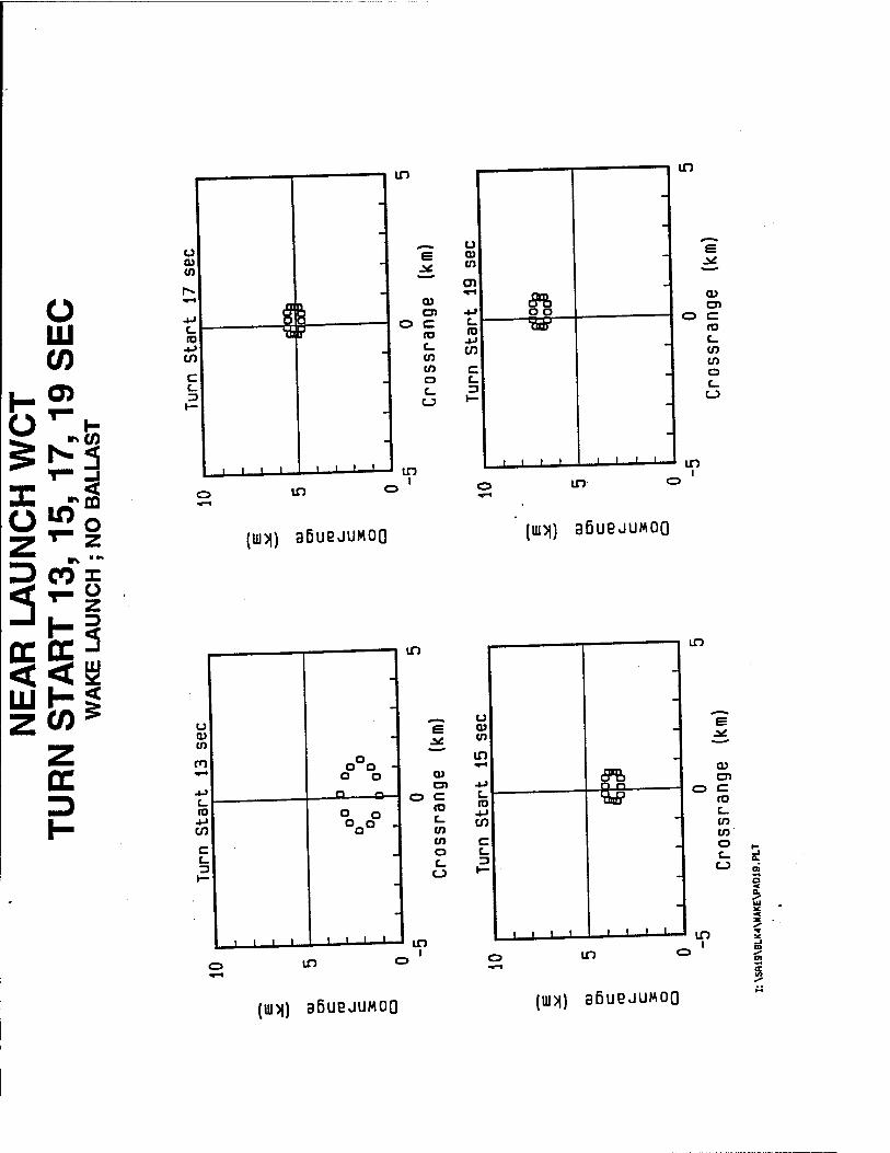
ü LU w
ü *" H
T- _J
3S CCDC << LÜ h-
CC
x o z
ü! <
(UJ>|) aßUBJUMOQ (Ul>|) aßUBJUMOQ
a Q.
(UJ>I) aßUBJUMOQ (Ul>|) BßUBJUMOQ

ü tu (/)
1- ü
25,2
7
i- (0 3
X *\ S ü z
CO CM o
D X < CM
eccc
Ü z
3 <<ä UJH <
Z (/)
z DC 3 H
u 0} U)
in cu jj c_ (D
tn
c c_ 3
o o o o
-O-0- Ob
_L_J 1—L
in
cu cn
o c (O c_ CO CO o c_ o
co m
J—• in i
-
u tu in
-
C\J o O -
■u o o O n
r_ (0
C/)
Ob
-
C r_
*—
1 1 _!__!__ 1, I—1—L_
in
cu cn
o c ro c tn cn o c_
C_3
in
co co m co
(uj)l) aßuejuMOQ (UJ>|) aßuejuMOQ
OJ
+j c_ ro
c C_ 3
CSD" o o o o
in
. u e tu .* tn
m cu
cu cn *J
o c c_ ro (0 c_ rn tn cn c o c_ c =>
C_) i—
i i ' ■ ' ' ■ ' ■ ' in CD m co
J I—I—L
Q53 O O o O
-o_p- CflD
in
cu cn
o e ro c_ tn tn o c_ o
o < o. tu
CO m co in
i
(UJ>{) aßUBJUMOQ (Ul>|) BßUBJUMOQ

ü 111 CO
-* CO j
U5i
-
o CU cn
.
A -
4J K§ c_ to
cn -
c c_ 3
i i i i 1 l J__l 1_
. u e 03 ^ cn
in ro O) o> ■M
o c c_ (D to c_ 4J
cn cn C o c_ c_ 3 o H-
CD an
o c (O c co cn o c_ o
in cn
in CM
in in m
in CM
in i
(Ul)|) aßUQJUMOQ (UI>|) aßUBJUMOQ
5 CM 2
CCDC3
<C<S LUHS Z<flS
z oc I-
-
u tu in .
cn ru AB 4J *r to
c c 3
1—
~
litt ....
. u e tu ^ cn
«H m
CD O» 4J
O C r_ CO to c ■4->
rn cn cn c o r_ e_ 3 u 1—
QJ CJ)
o er ro c_ cn cn o c_ CJ
a Q.
in m
in evi
in in ro
in CM
in i
(Ul)|) 36UEJUM0Q (Ul)|) BßUBJUMOQ

o CM
o ru
H W
CT
1, 41
, 43
SE
C
BA
LLA
ST
U CD 10
■*T
■M C_ ID
4-> en
c c_ 3
8
1
1
■
1
0
C
rossra
ng
e (
km) u
cu en
n
*J c_ (D •M CO
c c_ 3
1—
8 .*:
cu en
t i i i i i • t i i t i
o c ro c_ to to o c_ o
c r-
1 ■ i
3 O C in c
ru o O O | r*» in m
(UJ>I) aöuejuMOQ (Ul)|) aSuOJUMOQ
NE
AR L
AU
TU
RN S
TAR
T 37
, W
AK
E L
AU
NC
H
u 0) in
m ■M c_ fD -*J CO
c c 3
»—
# 0
2C
Cro
ss
ran
ge (
km) u
cu en
OT ro
c -M tn c c 3
1—.
8 )
2C
ige
(k
m)
i i i • i i 1 I ' 1 1 •
ro c_ CO CO o c_
c
i—i—|—i—i
3 C ir 1 P-
rvj > i )
C
i > c
ir
1 > c ■) p-
C\J
5
[UJ>|) aßUBJUMOQ (UI>|) aßUBJUMOQ

ü UJ W
I ->£B
U CD (/}
c_ ro ■M cn
c c_ 3
O o° o o
o o
°o o
o
QJ cn
o c CD c CD cn o c_ CJ
O CO
es O
oT
u cu in
o o° o o
IT) -
C_ ID ■M to
° o
o o
c c o
o°
1 1 1 1 1 1 1 1
o
CU cn
o c ro c_ cn cn o c_
CJ
o CD
o O
oT
(Ul)|) 36U9JUH0Q (tu>i) aöuejuMOQ
3 ccoc <<
7(0
x ü
3 <
u cu cn
in
CD ■>->
to C c
o oo o o -l
O o
oo OO O -
o
cu cn
o c CD c_ cn cn o c CJ
u cu cn
cn
o CO
o •NT
o
o
o o
8* o
O
CU CJi
o c cu c_ cn cn o c_
c_> S a.
O CD
CD
(UI>1) 36UBJUMOQ (lll>|) BßUBJUMOQ

Florida Keys Target Launch Siting Report Ballistic Missile Defense Organization
Annex C Aerial Photographs
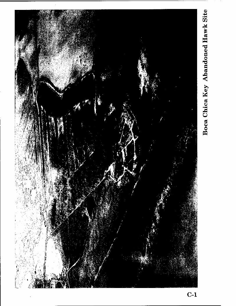
U)
0)
o
CO
CO o
u CO Ü o
PQ
C-l
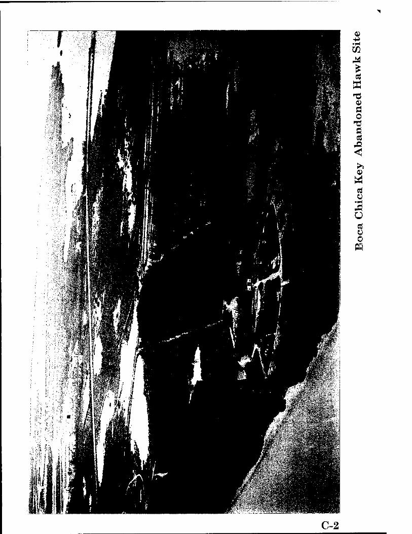
-ämm- mW- •KUH- -SKSJ *3fM '
mf i ilSt •
■-1 J ■'.& 1 ■ Ml
. i W ■'■■--■■Vvj? MI
.-•-i.-4 Sv jl
ctf E
Ö o
<
ü
ü d o
C-2
0>
CG
Ö
<
o Ö
C-3
CO CO Ö
■fl
o> ö
o
I—I
cd
C-4

a* • iH
W
0
0>
o
O
o
C-5

0) • fH
CO
(ß o 5H 0) <
u o
o
s*
C-6
Florida Keys Target Launch Siting Report Ballistic Missile Defense Organization
Annex D Economic Analysis
D
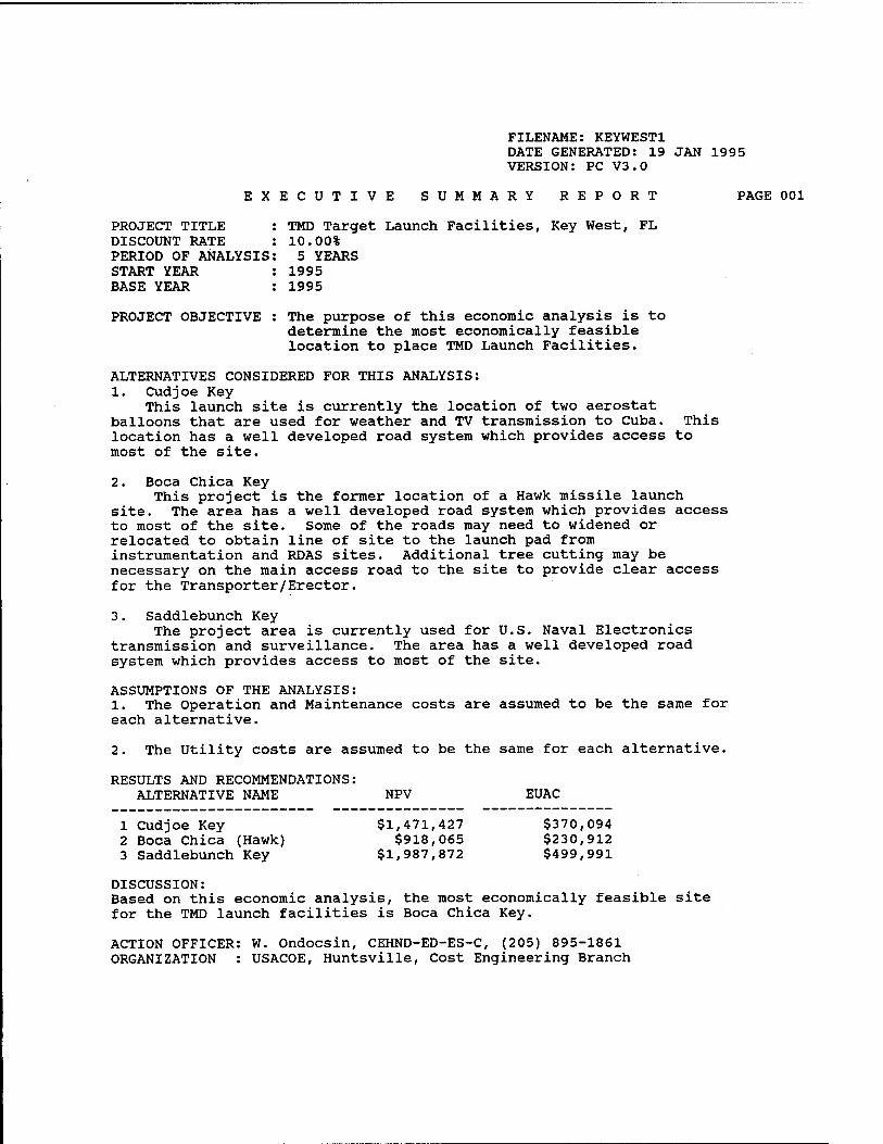
FILENAME: KEYWEST1 DATE GENERATED: 19 JAN 1995 VERSION: PC V3.0
EXECUTIVE SUMMARY REPORT PAGE 001
PROJECT TITLE : TMD Target Launch Facilities, Key West, FL DISCOUNT RATE : 10.00% PERIOD OF ANALYSIS: 5 YEARS START YEAR : 1995 BASE YEAR : 1995
PROJECT OBJECTIVE : The purpose of this economic analysis is to determine the most economically feasible location to place TMD Launch Facilities.
ALTERNATIVES CONSIDERED FOR THIS ANALYSIS: 1. Cudjoe Key
This launch site is currently the location of two aerostat balloons that are used for weather and TV transmission to Cuba. This location has a well developed road system which provides access to most of the site.
2. Boca Chica Key This project is the former location of a Hawk missile launch
site. The area has a well developed road system which provides access to most of the site. Some of the roads may need to widened or relocated to obtain line of site to the launch pad from instrumentation and RDAS sites. Additional tree cutting may be necessary on the main access road to the site to provide clear access for the Transporter/Erector.
3. Saddlebunch Key The project area is currently used for U.S. Naval Electronics
transmission and surveillance. The area has a well developed road system which provides access to most of the site.
ASSUMPTIONS OF THE ANALYSIS: 1. The Operation and Maintenance costs are assumed to be the same for each alternative.
2. The Utility costs are assumed to be the same for each alternative.
RESULTS AND RECOMMENDATIONS: ALTERNATIVE NAME NPV EUAC
1 Cudjoe Key $1,471,427 $370,094 2 Boca Chica (Hawk) $918,065 $230,912 3 Saddlebunch Key $1,987,872 $499,991
DISCUSSION: Based on this economic analysis, the most economically feasible site for the TMD launch facilities is Boca Chica Key.
ACTION OFFICER: W. Ondocsin, CEHND-ED-ES-C, (205) 895-1861 ORGANIZATION : USACOE, Huntsville, Cost Engineering Branch
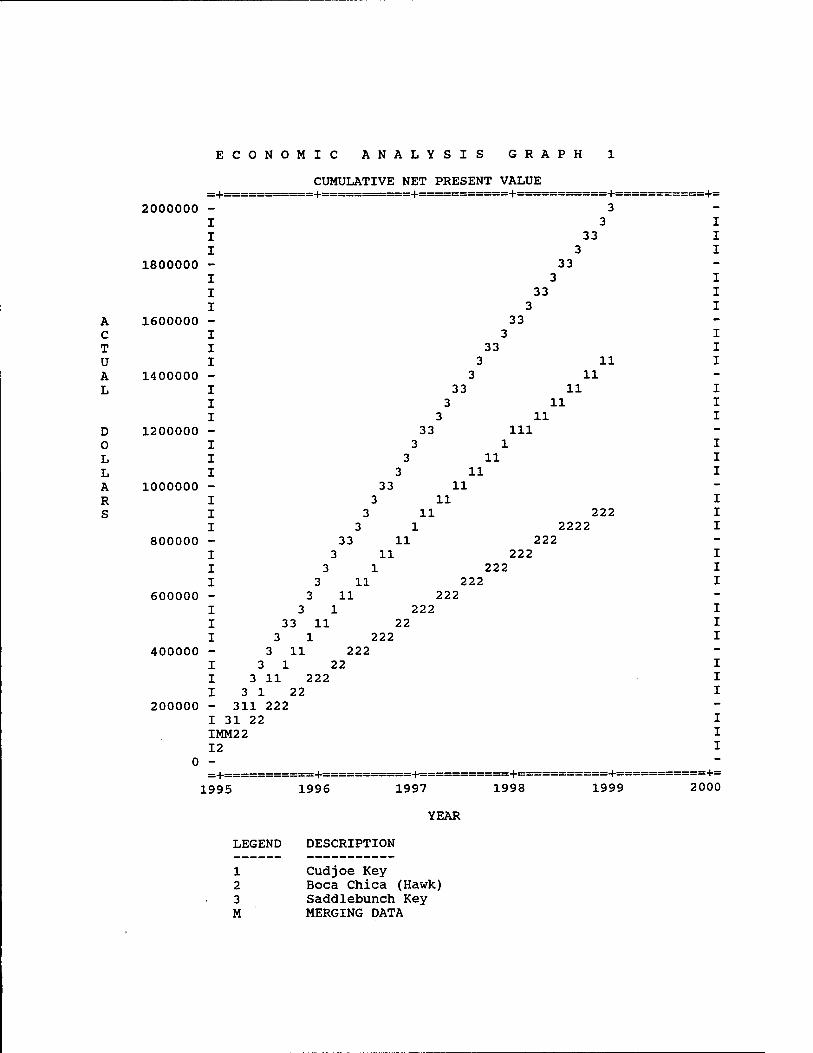
A C T U A L
D 0 L L A R S
ECONOMIC ANALYSIS GRAPH 1
CUMULATIVE NET PRESENT VALUE
2000000 - 3 - I 3 1 I 33 I I 3 1
1800000 - 33 - I 3 1 I 33 I I 3 1
1600000 - 33 - I 3 1 I 33 I I 3 11 I
1400000 - 3 11 - I 33 11 I I 3 11 I I 3 11 I
1200000 - 33 111 I 3 1 I I 3 11 I I 3 11 I
1000000 - 33 11 I 3 11 I I 3 11 222 I I 3 1 2222 I
800000 - 33 11 222 I 3 11 222 I I 3 1 222 I I 3 11 222 I
600000 - 3 11 222 I 3 1 222 I I 33 11 22 I I 3 1 222 I
400000 - 3 11 222 I 3 1 22 I I 3 11 222 I I 3 1 22 I
200000 - 311 222 I 31 22 I IMM22 I 12 I
0 -
1995 1996 1997 1998 1999 2000
YEAR
LEGEND DESCRIPTION
1 Cudjoe Key 2 Boca Chica (Hawk) 3 Saddlebunch Key M MERGING DATA

LIFE CYCLE COST REPORT
PROJECT/PROGRAM COSTS
PAGE 001
ALTERNATIVE 1: Cudj oe Key
YEAR
Construction Costs
(01)
TOTAL ANNUAL OUTLAYS
MIDDLE OF YEAR
DISCOUNT FACTORS
PRESENT VALUE
CUMULATIVE PRESENT VALUE
1995 1996 1997 1998 1999
$3,793,906 $0 $0 $0 $0
$3,793,906 $0 $0 $0 $0
0.953 0.867 0.788 0.716 0.651
$3,617, 348 $0 $0 $0 $0
$3,617,348 $3,617,348 $3,617,348 $3,617,348 $3,617,348
%NPV 245.84 $3,617,348
DISCOUNTING CONVENTION M-O-Y
YEAR
PRESENT VALUE RESIDUAL
CUMULATIVE NET PRESENT VALUE
1995 1996 1997 1998 1999
$3,526,914 $3,129,770 $2,769,231 $2,442,225 $2,145,921
$90,434 $487,578 $848,117
$1,175,123 $1,471,427
%NPV -145.84 $2,145,921
DISCOUNTING CONVENTION M-O-Y
EQUIVALENT UNIFORM ANNUAL COST = $370,094 (10.00% DISCOUNT RATE, 5 YEARS)
EXPENSE ITEM 1 USED INFLATION INDEX 1 - TRI-SERVICE MCP INDX.
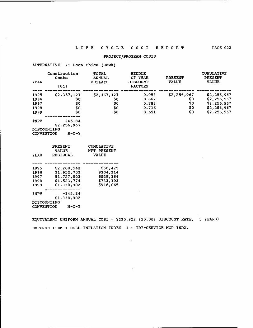
LIFE CYCLE COST REPORT
PROJECT/PROGRAM COSTS
ALTERNATIVE 2: Boca Chica (Hawk)
PAGE 002
Construction TOTAL MIDDLE CUMULATIVE Costs ANNUAL OF YEAR PRESENT PRESENT
YEAR (01)
OUTLAYS DISCOUNT FACTORS
VALUE VALUE
1995 $2,367,127 $2,367,127 0.953 $2,256, 967 $2,256,967 1996 $0 $0 0.867 $0 $2,256,967 1997 $0 $0 0.788 $0 $2,256,967 1998 $0 $0 0.716 $0 $2,256,967 1999 $0 $0 0.651 $0 $2,256,967
%NPV 245.84 $2,256,967
DISCOUNTING CONVENTION M-O-Y
PRESENT CUMULATIVE VALUE NET PRESENT
YEAR RESIDUAL VALUE
1995 $2,200,542 $56,425 1996 $1,952,753 $304,214 1997 $1,727,803 $529,164 1998 $1,523,774 $733,193 1999 $1,338,902 $918,065
%NPV -145.84 $1,338,902
DISCOUNTING CONVENTION M-O-Y
EQUIVALENT UNIFORM ANNUAL COST = $230,912 (10.00% DISCOUNT RATE,
EXPENSE ITEM 1 USED INFLATION INDEX 1 - TRI-SERVICE MCP INDX.
5 YEARS)
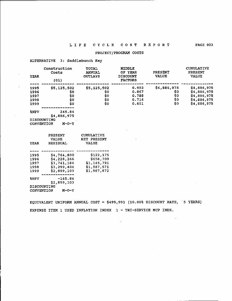
LIFE CYCLE COST REPORT
PROJECT/PROGRAM COSTS
ALTERNATIVE 3: Saddlebunch Key
PAGE 003
Construction TOTAL MIDDLE CUMULATIVE Costs ANNUAL OF YEAR PRESENT PRESENT
YEAR OUTLAYS DISCOUNT VALUE VALUE (01) FACTORS
1995 $5,125,502 $5,125,502 0.953 $4, 886, 975 $4,886,975 1996 $0 $0 0.867 $0 $4,886,975 1997 $0 $0 0.788 $0 $4,886,975 1998 $0 $0 0.716 $0 $4,886,975 1999 $0 $0 0.651 $0 $4,886,975
%NPV 245.84 $4,886,975
DISCOUNTING CONVENTION M-O-Y
PRESENT CUMULATIVE VALUE NET PRESENT
YEAR RESIDUAL VALUE
1995 $4,764,800 $122,175 1996 $4,228,266 $658,709 1997 $3,741,184 $1,145,791 1998 $3,299,404 $1,587,571 1999 $2,899,103 $1,987,872
%NPV -145.84 $2,899,103
DISCOUNTING CONVENTION M-O-Y
EQUIVALENT UNIFORM ANNUAL COST = $499,991 (10.00% DISCOUNT RATE,
EXPENSE ITEM 1 USED INFLATION INDEX 1 - TRI-SERVICE MCP INDX.
5 YEARS)
LIFE CYCLE COST REPORT PAGE 004
SOURCE AND DERIVATION OF COSTS AND BENEFITS: 1. Costs are derived from MCACES Gold 5.30 and R.S. Means Cost Data 1994.
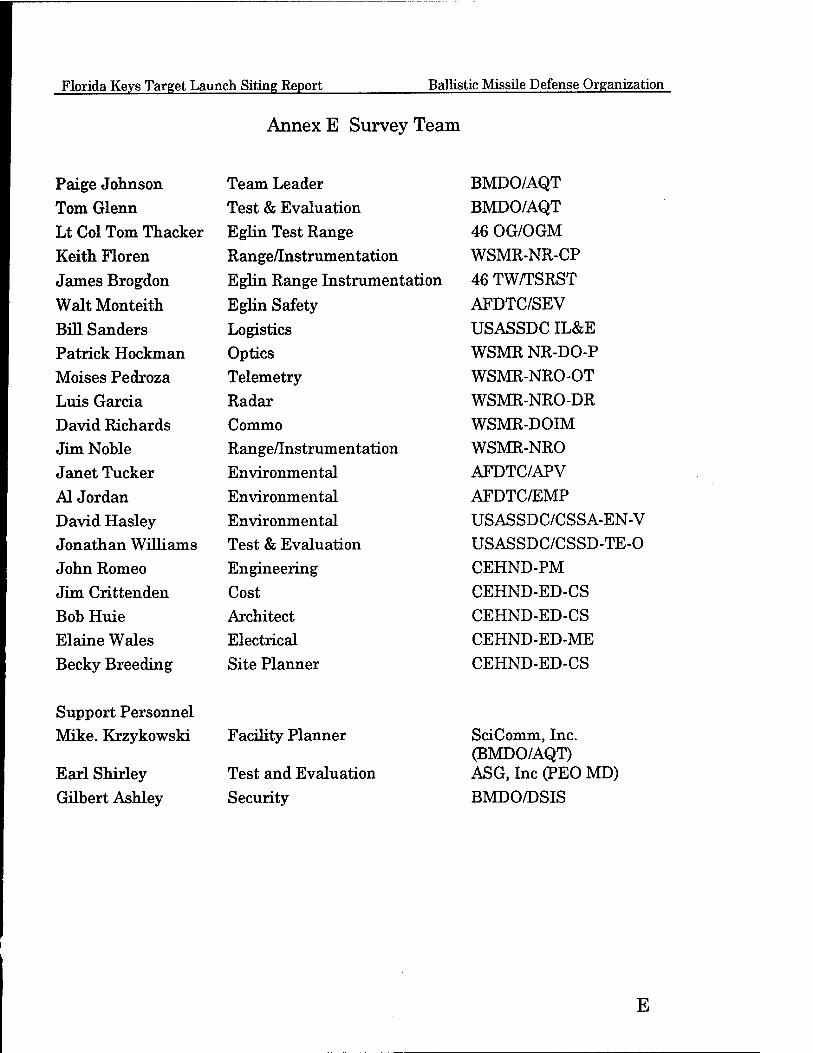
Florida Keys Target Launch Siting Report Ballistic Missile Defense Organization
Annex E Survey Team
Paige Johnson Tom Glenn Lt Col Tom Thacker Keith Floren
James Brogdon
Walt Monteith Bill Sanders Patrick Hockman Moises Pedroza Luis Garcia David Richards Jim Noble Janet Tucker
Al Jordan David Hasley Jonathan Williams John Romeo Jim Crittenden Bob Huie Elaine Wales Becky Breeding
Team Leader Test & Evaluation Eglin Test Range Range/Instrumentation
Eglin Range Instrumentation
Eglin Safety Logistics Optics Telemetry Radar Commo Range/Instrumentation
Environmental Environmental Environmental Test & Evaluation Engineering
Cost Architect Electrical Site Planner
BMDO/AQT BMDO/AQT
46 OG/OGM WSMR-NR-CP
46 TW/TSRST
AFDTC/SEV USASSDC IL&E WSMR NR-DO-P WSMR-NRO-OT WSMR-NRO-DR WSMR-DOIM WSMR-NRO AFDTC/APV
AFDTC/EMP USASSDC/CSSA-EN-V USASSDC/CSSD-TE-0 CEHND-PM
CEHND-ED-CS CEHND-ED-CS CEHND-ED-ME
CEHND-ED-CS
Support Personnel Mike. Krzykowski
Earl Shirley Gilbert Ashley
Facility Planner
Test and Evaluation Security
SciComm, Inc. (BMDO/AQT) ASG, Inc (PEO MD) BMDO/DSIS
E